US12123230B2 - Locking device for a vehicle door, and method - Google Patents
Locking device for a vehicle door, and method Download PDFInfo
- Publication number
- US12123230B2 US12123230B2 US17/233,723 US202117233723A US12123230B2 US 12123230 B2 US12123230 B2 US 12123230B2 US 202117233723 A US202117233723 A US 202117233723A US 12123230 B2 US12123230 B2 US 12123230B2
- Authority
- US
- United States
- Prior art keywords
- inhibiting
- pawl
- rotary latch
- lever
- locking device
- Prior art date
- Legal status (The legal status is an assumption and is not a legal conclusion. Google has not performed a legal analysis and makes no representation as to the accuracy of the status listed.)
- Active, expires
Links
Images


Classifications
-
- E—FIXED CONSTRUCTIONS
- E05—LOCKS; KEYS; WINDOW OR DOOR FITTINGS; SAFES
- E05B—LOCKS; ACCESSORIES THEREFOR; HANDCUFFS
- E05B83/00—Vehicle locks specially adapted for particular types of wing or vehicle
- E05B83/16—Locks for luggage compartments, car boot lids or car bonnets
- E05B83/24—Locks for luggage compartments, car boot lids or car bonnets for car bonnets
-
- E—FIXED CONSTRUCTIONS
- E05—LOCKS; KEYS; WINDOW OR DOOR FITTINGS; SAFES
- E05B—LOCKS; ACCESSORIES THEREFOR; HANDCUFFS
- E05B81/00—Power-actuated vehicle locks
- E05B81/02—Power-actuated vehicle locks characterised by the type of actuators used
- E05B81/04—Electrical
-
- E—FIXED CONSTRUCTIONS
- E05—LOCKS; KEYS; WINDOW OR DOOR FITTINGS; SAFES
- E05B—LOCKS; ACCESSORIES THEREFOR; HANDCUFFS
- E05B85/00—Details of vehicle locks not provided for in groups E05B77/00 - E05B83/00
- E05B85/20—Bolts or detents
- E05B85/24—Bolts rotating about an axis
-
- E—FIXED CONSTRUCTIONS
- E05—LOCKS; KEYS; WINDOW OR DOOR FITTINGS; SAFES
- E05B—LOCKS; ACCESSORIES THEREFOR; HANDCUFFS
- E05B85/00—Details of vehicle locks not provided for in groups E05B77/00 - E05B83/00
- E05B85/20—Bolts or detents
- E05B85/24—Bolts rotating about an axis
- E05B85/243—Bolts rotating about an axis with a bifurcated bolt
-
- E—FIXED CONSTRUCTIONS
- E05—LOCKS; KEYS; WINDOW OR DOOR FITTINGS; SAFES
- E05B—LOCKS; ACCESSORIES THEREFOR; HANDCUFFS
- E05B85/00—Details of vehicle locks not provided for in groups E05B77/00 - E05B83/00
- E05B85/20—Bolts or detents
- E05B85/24—Bolts rotating about an axis
- E05B85/26—Cooperation between bolts and detents
Definitions
- the present disclosure relates generally to locking devices for a hinged panel of a motor vehicle and more particularly to a locking device for a bonnet or hood.
- This section provides background information related to locking devices for motor vehicles which is not necessarily prior art.
- the bonnet i.e. hood region requires different safety precautions as a result of the fact that, during travel, the bonnet should not swing up accidentally, in which case it could block the driver's view. Therefore, in addition to the rotary latch, conventional bonnet locking devices also have a so-called safety catch. If the rotary latch is moved from its latched position into its open position, and if the locking element is released, the bonnet still has the safety catch engaging behind it, typically at a different location, and then, for example manually, can be disengaged from the safety catch and opened.
- one of the mouth flanks of the rotary latch is typically in the form of a safety catch.
- a rotary latch however, then requires no longer to provide just a locking position, but typically also provide a safety-catch position, which, in terms of the opening sequence, follows the locking position.
- the inhibiting pawl it is possible for the inhibiting pawl to be actuated twice, and prior to this for the rotary latch to perform an inhibiting or arresting action twice during an opening operation, that is to say first of all in the locking position and, prior to a second inhibiting pawl actuation, then in the safety-catch position.
- a first inhibiting pawl is assigned to a front side of the rotary latch (for arresting purposes in a locking position) and a rear side of the rotary latch has arranged on it a second inhibiting pawl for arresting the rotary latch in a safety-catch position.
- these two inhibiting pawls are usually assigned to separate actuating means, typically in the form of manually actuable Bowden cables. A vehicle driver can actuate the first inhibiting pawl manually from the vehicle interior and can then actuate the second inhibiting pawl manually from the outside of the vehicle.
- the invention is therefore characterized in that first and second inhibiting pawls can be moved from their respective inhibiting position into a release position by the use of the same (i.e. common) actuating means.
- first and second inhibiting pawls can be moved from their respective inhibiting position into a release position by the use of the same (i.e. common) actuating means.
- the concept of the invention is to make it possible for the two inhibiting pawls to be displaced with the aid of a single drive mechanism.
- the single drive mechanism may be an electric motor which can act on the actuating means of the locking device via a Bowden cable or the like, or also directly.
- the actuating means may be, for example, a point of attachment for a Bowden cable (or some other operating cable) or a linkage which, as a result of being activated, or actuated, causes at least one of the inhibiting pawls to be transferred into its release position.
- the actuating means may be formed here, for example, by an arm or one end of a drive lever, or even by the drive lever itself, or it may comprise such a drive lever and/or also the Bowden cable.
- the actuating means can be activated either just manually (for example with the aid of a handle or of a manually actuable Bowden cable or the like) or automatically, that is to say with the aid of a drive mechanism, which may be designed, for example, in the form of an electric motor.
- the electric motor can cause the actuating means to be activated.
- Each actuating means here can cause one of the inhibiting pawls to be displaced.
- the activation of the electric motor is typically initiated manually (for example by a vehicle driver pressing a button) or after a certain period of time has elapsed, for example a certain period of time after an engine has been switched off or a test system or the like has been activated.
- the actuating means here is triggered or activated both in order to displace the first inhibiting pawl and to displace the second inhibiting pawl. These two activations of the actuating means take place preferably at different points in time.
- the actuating means When the actuating means is activated for a first time, it can act for example directly or indirectly on the first inhibiting pawl and when the actuating means is activated for a second time, at a different point in time, it can then act directly or indirectly on the second inhibiting pawl, in each case in order to move the inhibiting pawl into the respective release position.
- the rotary latch In this release position, the rotary latch is typically released by the inhibiting pawl and can pivot in the opening direction, preferably under spring prestressing or manually.
- the actuating means can act at any rate indirectly both on the first inhibiting pawl and on the second inhibiting pawl.
- the actuating means can preferably be coupled to the first inhibiting pawl and/or to the second inhibiting pawl for this purpose.
- the inhibiting pawls each have an inhibiting position in which they arrest or inhibit the rotary latch in its locking position (first inhibiting pawl) and in its safety-catch position (second inhibiting pawl).
- the two can each be transferred into a (different) release position.
- This movement into the release position takes place by virtue of the actuating means being activated, for example with the aid of the (one) electric motor.
- the actuating means can act on the respective inhibiting pawl preferably indirectly, that is to say via a gear mechanism or lever system or the like.
- An arresting action by one of the inhibiting pawls is therefore understood to mean, in the context of the present application, a blocking action, that is to say blocking in the movement direction of the rotary latch in the opening direction.
- a blocking action that is to say blocking in the movement direction of the rotary latch in the opening direction.
- the first inhibiting pawl will typically always establish contact with, and arrest, the rotary latch.
- the second inhibiting pawl can arrest, that is to say inhibit, the rotary latch in its safety-catch position in a contactless manner, in particular in respect of the opening direction thereof.
- the actuating means When the actuating means is activated for a first time, it can typically be coupled to the first inhibiting pawl in order to displace the same. It is then typically uncoupled from the first inhibiting pawl. This is then followed by coupling to the second inhibiting pawl (for example prior to the actuating means being activated for a second time). It is then possible for a second activation of the actuating means to transfer the second inhibiting pawl into its release position, in which case the rotary latch is then typically in a fully released state.
- a locking element (which is typically assigned to the vehicle door or bonnet) can then pass all the way out of the mouth region of the rotary latch, in particular out of the safety-catch region. This is not typically possible in a safety-catch position of the rotary latch, certainly not in a locking position of the rotary latch.
- the first and the second inhibiting pawls can typically cooperate with other, in particular opposite, surfaces of the rotary latch, in order to arrest the rotary latch in the respective position. It is thus possible for the first inhibiting pawl to cooperate typically with a locking-action inhibiting surface of the rotary latch (in a preferred exemplary embodiment, in addition, also with a preliminary-latching surface) and for the second inhibiting pawl to cooperate typically with a safety-catch-action inhibiting surface of the rotary latch.
- the rotary latch typically has a safety-catch-like portion on a flank assigned to the mouth region.
- said safety-catch portion can for example (when viewed from the outside) partially cover over the mouth of the rotary latch.
- the rotary latch is typically prestressed into its open position, for example by a spring or the like assigned to its pivot pin.
- the prestressing direction leads from the locking position into the safety-catch position and then onwards into a fully open position.
- the locking element In order that the locking element can be guided out of the safety-catch-like mouth of the rotary latch in the fully open position of the latter, the locking element is typically assigned a separate lifting lever, which can be fitted in particular coaxially in relation to one of the inhibiting pawls, in particular the first inhibiting pawl, and is likewise prestressed in the opening direction.
- a lifting function is also possible via a lifting spring outside the lock.
- the locking element itself is typically arranged on the vehicle door, that is to say for example a hinged opening panel, in particular on a bonnet, whereas the locking device is typically arranged on the vehicle body, for example on a separate housing or on an installation plate or the like. It is also conceivable in principle, however, for this arrangement to be the other way round.
- the locking element is typically a central leg of a U-shaped striker or a striker pin or a similarly suitable element.
- the vehicle door is typically a motor-vehicle bonnet, in which a safety-catch-like formation of the rotary latch is particularly expedient, and so the two separate inhibiting pawls typically become necessary in the first place.
- the door may also, in principle, be any other kind of vehicle door, for example a rear door/hatch or the like.
- the vehicle doors here are associated preferably with motor vehicles, in particular passenger vehicles.
- the two inhibiting pawls that is to say the first inhibiting pawl and the second inhibiting pawl, to be arranged at a distance from one another.
- one inhibiting pawl to be assigned to the front side of a rotary latch and for the other inhibiting pawl to be assigned to the rear side of the rotary latch.
- the inhibiting pawls are arranged here such that they do not interengage, and in particular are not coupled in terms of movement either.
- the two inhibiting pawls are preferably arranged non-coaxially in relation to one another, that is to say they are not fitted on the same pivot pin.
- the actuating means can be triggered or activated in a motor-controlled manner. It would basically also be possible for the device to provide for a manual activation of the actuating means, for example with the aid of a handle or the like.
- the actuating means is therefore activated, or actuated, preferably in a motor-controlled manner, in particular with the aid of an electric motor.
- the motor can act, for example, on an operating cable (or a Bowden cable) which has one end secured to the actuating means or which helps to form the actuating means.
- the motor preferably the electric motor, ensures displacement both of the first inhibiting pawl and of the second inhibiting pawl, this being done, of course, indirectly, with the aid of the actuating means and of the possibly associated further lever elements, such as a drive lever or the like.
- a first actuation of the motor here can cause a first activation of the actuating means of the device and a displacement of the first inhibiting pawl.
- a second actuation of the motor can cause a second activation of the actuating means and a displacement of the second inhibiting pawl. It is possible here for example for a drive lever to be automatically coupled to, and uncoupled from, the first or the second inhibiting pawl.
- the actuating means is preferably made for the actuating means to be capable of being activated only by the motor; no manual activation being provided for.
- the actuating means that is to say separate operation in each case
- the individual inhibiting pawls possibly to be actuated manually, separately in each case, for example in an accident situation or in the event of the vehicle electronics failing, via a handle.
- the actuating means is assigned a drive lever.
- This drive lever can act directly or indirectly both on the first inhibiting pawl and also on the second inhibiting pawl.
- the actuating means here typically comprises one end of the drive lever or an arm of the drive lever or the like. Further levers may be arranged on the drive lever in order to act on the two inhibiting pawls in the manner of a linkage or drive.
- the drive lever is preferably fitted coaxially with the rotary latch. This makes it possible to simplify the geometry of the locking device and to reduce the number of components required.
- the drive lever moreover, can be displaced in a motor-controlled manner, or by an electric motor, for example with the aid of a Bowden cable or the like.
- the drive lever may have an actuating arm, which can act in particular directly on the inhibiting pawl.
- the actuating arm can comprise, for example, a contact bolt or the like, which can be brought into contact with a contact surface of the inhibiting pawl. Establishing contact in this way may also be referred to as coupling.
- a contact bolt use may also be made of some other suitable element, for example also a flat surface or the like arranged on the actuating arm.
- the drive lever can typically also have at least one operating arm, on which the actuating means is provided.
- a coupling lever for actuating the second inhibiting pawl is arranged on the drive lever.
- this coupling lever may be arranged coaxially in relation to the aforementioned actuating lever (if the lever is provided in the first place).
- the coupling lever here is typically articulated or arranged in a pivotable manner on the drive lever. It may have a coupling state, in which it is coupled to the second inhibiting pawl. In this state, it can, for example, engage behind said inhibiting pawl. In another, uncoupled state, the coupling lever may be arranged in particular at a distance from the second inhibiting pawl.
- the second inhibiting pawl can be transferred from its inhibiting position into its release position, at any rate when the coupling lever and second inhibiting pawl are coupled.
- the coupling lever can achieve contact with the second inhibiting pawl via a contact surface, for example in the form of a contact bolt.
- the direct line of connection between the contact surface on the actuating lever and the pivot pin of the actuating lever and also the direct line of connection between the pivot pin of the drive lever and the pivot pin of the first inhibiting pawl can likewise form a trapezium, preferably a parallelogram.
- an actuating lever is also actually provided in addition to the coupling lever, these can be prestressed in relation to one another, in particular if they are fitted coaxially.
- the extent of prestressing of the one lever, in particular the coupling lever can exceed the prestressing of the other lever here, in order thus to make possible a rocker-like effect for coupling the two levers to, and uncoupling them from, one (or both) of the inhibiting pawls.
- a closing pawl for the rotary latch can preferably be arranged on the drive lever. It is possible for this closing pawl to engage, for example, in a closing notch of the rotary latch or to engage behind a nose of the rotary latch in order to transfer the latter, in the manner of a closing aid, from a preliminary-latching position to a fully locked position of the rotary latch.
- the closing pawl may be assigned, in particular, to the operating arm of the drive lever, said operating arm also having the actuating means arranged on it or forming the actuating means. It is possible here for the closing pawl to be prestressed in the direction of the rotary latch or also to be guided in a guide track on the vehicle body, or the like.
- the gear mechanism which is assigned to the actuating means can comprise in particular the drive lever, to be capable of being coupled to the first inhibiting pawl and also uncoupled again therefrom.
- a first activation of the actuating means can typically result in coupling to the first inhibiting pawl. This first inhibiting pawl can then be actuated (or can be actuated in the process).
- the gear mechanism can then ensure transfer of the second inhibiting pawl into its release position, and preferably then also uncoupling from the second inhibiting pawl.
- the stated object is achieved by a method according to claim 10.
- This method is characterized, in particular, in that the first and second inhibiting pawls are moved one after the other from their respective inhibiting position into a release position by the same actuating means, in particular by virtue of the actuating means being activated at two different points in time.
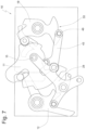
- FIG. 1 shows a highly schematic, partially transparent, section-like side view of a first exemplary embodiment of a locking device according to the invention with a rotary latch fully locked and a drive lever located in an initial position;
- FIG. 3 shows the locking device according to FIG. 2 with the rotary latch pivoted to a slight extent
- FIG. 4 shows the locking device according to FIG. 3 with a rotary latch located in a safety-catch position
- FIG. 5 shows the locking device according to FIG. 4 with the drive lever partially pivoted back
- FIG. 6 shows the locking device according to FIG. 5 with engagement behind a second inhibiting pawl
- FIG. 7 shows the locking device according to FIG. 6 with the second inhibiting pawl transferred into a release position
- FIG. 8 shows the locking device according to FIG. 7 with a latch-in lever engaged
- FIG. 9 shows the locking device according to FIG. 8 with the latch-in lever deflected by the rotary latch and the rotary latch located in the fully open position;
- FIG. 10 shows the locking device according to FIG. 9 during a locking operation, in a preliminary-latching position
- FIG. 11 shows a second exemplary embodiment of the locking device according to the invention, more or less in a view according to FIG. 1 and with the drive omitted.
- FIG. 1 shows a first exemplary embodiment of a locking device 10 according to the invention in which a rotary latch 11 is arrested by a first inhibiting pawl 12 in an illustrated locking position.
- Both the first inhibiting pawl 12 and the rotary latch 11 are arranged on a housing and/or on an installation plate 13 such that they can be pivoted about their respective pivot pins 14 , 15 .
- the front side of the rotary latch 11 (in other words on the left-hand side in FIG. 1 ) is assigned the first inhibiting pawl 12
- the rear side of the rotary latch 11 (in other words on the right-hand side in FIG. 1 ) is assigned a second inhibiting pawl 19 , which can also be referred to as an inhibiting-pawl safety hook.
- This second inhibiting pawl 19 is likewise arranged on the installation plate 13 such that it can be pivoted via a pivot pin 20 and is prestressed in the direction of the rotary latch 11 , in other words in the anticlockwise direction in FIG. 1 .
- the second inhibiting pawl 19 is assigned a latch-in lever 21 in a parallel plane, albeit likewise arranged in a pivotable manner on the installation plate 13 , and a latching end 22 of said lever can engage, in a manner which will also be described at a later stage in the text, in a latching indent 23 of the second inhibiting pawl 19 .
- the second inhibiting pawl 19 additionally has an inhibiting nose 24 , which can interact, in a manner which likewise will also be described at a later stage in the text, with a blocking nose 25 of the rotary latch 11 .
- the rotary latch 11 additionally has formed on it a projecting actuating bead 26 which projects in particular out of the plane of the figure and/or is arranged behind the same and which can interact, in a manner which will also be described at a later stage in the text, with an actuating end 27 of the latch-in lever 21 .
- a drive lever 28 is arranged coaxially with the rotary latch 11 , on the common pivot pin 15 , on the installation plate 13 .
- the drive lever 28 is illustrated in its initial position in FIG. 1 and can have, in particular, a plurality of arms.
- An operating arm 29 here has arranged on it an actuating means 30 , which may be provided, for example, by an engaging protuberance and/or part of the operating arm 29 .
- the actuating means 30 is connected to a drive mechanism 32 (merely indicated) via an operating cable 31 , in particular a Bowden cable, or a linkage or the like.
- the drive mechanism 32 may be, for example, a motor, in particular an electric motor.
- the drive lever 28 can thus basically be pivoted, around its pin 15 , by the drive mechanism 32 .
- the drive lever 28 has a further arm, that is to say the contact arm 33 , on which is arranged a contact element, for example a contact bolt 34 , in order to establish contact with, and actuate, the first inhibiting pawl 12 .
- a contact element for example a contact bolt 34
- the contact bolt 34 here is not yet quite in contact with a contact surface 35 of a release arm 36 of the first inhibiting pawl 12 .
- a closing pawl 37 is additionally arranged, such that it can be pivoted about a pin 38 , in the region of the operating arm 29 of the drive lever 28 .
- the closing pawl 37 basically serves—in a manner which will also be described at a later stage in the text—for a locking operation of the device 10 and for an optional, automatic closing operation of the rotary latch 11 .
- the pawl 37 basically has a closing surface 39 , which can then interact, in a manner which likewise will also be precisely described at a later stage in the text, with a closing protrusion 40 of the rotary latch 11 .
- closing pawl 37 it is possible here for the closing pawl 37 to be prestressed about the pin 38 in the direction of the rotary latch 11 or, as an alternative, to engage by way of a guide bolt 41 (merely indicated) in a guide track or the like on the vehicle body or housing (said guide track not being illustrated in the figures).
- a coupling lever 43 is articulated in the region of the attachment arm 42 of the drive lever 28 .
- the coupling lever 43 is arranged on the drive lever 28 via a pivot pin 44 and is prestressed in relation to the drive lever, with the aid of spring elements (not illustrated), in the direction of the rotary latch 11 , and in the direction of the second inhibiting pawl 19 (in other words in the counterclockwise direction in FIG. 1 ).
- a guide bolt 45 which is formed on the coupling lever 43 , butts against a guide surface 46 of the rotary latch 11 .
- the guide surface 46 here may be a constituent part of a second, rear-side mouth 47 of the rotary latch 11 .
- the coupling lever 43 has, at a coupling end 48 , a coupling bolt 49 , which can basically be assigned to a rear-engagement region 50 of the second inhibiting pawl 19 .
- the coupling bolt 49 is not yet engaging in the rear-engagement region 50 of the second inhibiting pawl 19 . Therefore, in this sense, the coupling lever 43 is not yet coupled to the second inhibiting pawl 19 (and, therefore, nor is the drive lever 28 or the actuating means 30 either).
- the drive mechanism 32 can be actuated. This results, via the linkage or the operating cable 31 , in an activation of the actuating means 30 and subjects the operating arm 29 of the drive lever 28 , for example, to a tensile force, to the left (in the direction of the drive 32 ) in FIG. 1 .
- the drive mechanism 32 can be actuated here, for example with the aid of a button, switch or the like, by a driver sitting in the cockpit of the vehicle.
- the drive lever 28 can then be pivoted, that is to say around the pivot pin 15 (in other words in the clockwise direction in FIG. 2 ), from a position according to FIG. 1 (so-called initial position) into the position illustrated in FIG. 2 .
- the contact bolt 34 of the contact arm 33 of the drive lever 28 here finally comes into contact with the contact surface 35 of the release arm 36 of the first inhibiting pawl 12 , and can thus transfer the inhibiting pawl 12 , around its pivot pin 14 , (counter to the prestressing force of the first inhibiting pawl 12 ) from the inhibiting position illustrated in FIG. 1 into the release position illustrated in FIG. 2 .
- the rotary latch 11 has now been released (by the first inhibiting pawl 12 ) and, starting from the position according to FIG. 2 , can pivot in the opening direction ⁇ in the clockwise direction around its pivot pin 15 , with possible assistance from the lifting lever 51 , until it reaches its safety-catch position according to FIG. 4 .
- FIG. 2 Prior to this happening, however, let us refer back once again to FIG. 2 , from which it is evident in particular in comparison with FIG. 1 that the coupling lever 43 has been pivoted along with the drive lever 28 and the coupling bolt 49 has thus clearly passed out of the rear-engagement region 50 of the second inhibiting pawl 19 .
- the coupling lever 43 owes the position illustrated in FIG. 2 here to its guide bolt 45 , which has now penetrated into the rear mouth 47 of the rotary latch 11 , and has been guided in particular along the upper edge thereof which forms the guide surface 46 .
- the coupling lever 43 in FIGS. 1 to 3 is in an identical position—possibly by chance—relative to the drive lever 28 .
- This relative position changes, however, as movement progresses, as indicated in FIG. 4 , which then—as already described—shows the safety-catch position of the rotary latch 11 .
- the rotary latch 11 is blocked by the second inhibiting pawl 19 with the aid of the inhibiting nose 24 .
- the inhibiting nose 24 is located in the pivoting path of the rotary latch 11 , without actually, in the present exemplary embodiment, establishing contact therewith.
- the drive lever 28 pivots around its pivot pin 15 again in the direction of its initial position, in other words in the counterclockwise direction in FIG. 5 .
- the first inhibiting pawl 12 is released as a result, and said inhibiting pawl can engage, in its prestressing direction, in relation to the rotary latch 11 and position itself against the latter.
- the coupling bolt 49 of the coupling lever 43 passes, via the position illustrated in FIG. 5 , into engagement with the second inhibiting pawl 19 , which position is illustrated in FIG. 6 and in which the coupling bolt is fully incorporated in the rear-engagement region 50 of the second inhibiting pawl 19 .
- the coupling lever 43 has been coupled to the second inhibiting pawl 19 and the contact arm 33 has been uncoupled again from the first inhibiting pawl 12 .
- the drive lever 28 assumes its initial position.
- the drive mechanism 32 which is illustrated schematically merely in FIG. 1 , is activated for a second time, the drive lever 28 pivots anew about its pivot pin 15 into the position illustrated in FIG. 7 .
- it can also deflect the first inhibiting pawl 12 here, although this is not imperative and takes place merely for geometry-related reasons.
- the more critical factor is that, during the illustrated pivoting action—in other words in the clockwise direction in the figures—from its initial position according to FIG. 6 into the position according to FIG.
- the drive lever 28 carries along the coupling lever 43 and, in the process, transfers the second inhibiting pawl 19 (by virtue of the coupling lever 43 and inhibiting pawl 19 being coupled via the coupling bolt 49 and the rear-engagement region 50 ) into the release position. In this position, the second inhibiting pawl 19 can release the rotary latch 11 .
- the latch-in lever 21 moves about its pivot pin, in the clockwise direction in the figures, from the position illustrated in FIG. 7 and to engage in the latching indent 23 of the inhibiting pawl 19 .
- the latch-in lever 21 and the second inhibiting pawl 19 are actually arranged in different planes.
- the latch-in lever 21 has the latching end 22 , which can project, or similar, for example into the plane of the second inhibiting pawl 19 .
- the second inhibiting pawl 19 is therefore kept open in FIG. 8 , and the drive lever 28 has been pivoted back into its initial position.
- release via the second inhibiting pawl 19 located in the release position can thus then cause the rotary latch 11 to pivot onwards, around its pivot pin 15 , into the fully open position according to FIG. 9 .
- the locking element 16 it is possible here for the locking element 16 to pass out of the mouth 17 of the rotary latch 11 , if appropriate past the safety-catch-like portion 52 of the rotary latch 11 .
- a vehicle driver can then simply prop up or raise up, or similar, the hinged opening panel connected to the locking element 16 . It is clear that, going between FIGS.
- the latch-in lever 21 is raised out of the latching indent 23 of the second inhibiting pawl 19 by the rotary latch 11 (in other words it is pivoted in the anticlockwise direction in FIG. 9 ).
- Both elements 26 , 27 here are arranged essentially behind the plane of the figure.
- the second inhibiting pawl 19 is therefore released as a result and can engage, in the anticlockwise direction in the figures, in its position illustrated in FIG. 9 .
- the bonnet can simply pivot automatically (and without any further action on the part of the closing pawl 37 ) into the main-latching position, or locking position, illustrated in FIG. 1 .
- the force is not sufficient for this purpose, and if the bonnet is placed onto the vehicle, merely with a small amount of pressure being applied, counter to the force of the lifting lever, this can be automatically detected by the vehicle or the device 10 .
- the drive mechanism 32 can subject the actuating means 30 to such a force that the drive lever 28 then pivots in a second direction Z, that is to say in the counterclockwise direction in the figures, from the initial position illustrated in FIG. 10 .
- the drive lever 28 here carries along the closing pawl 37 , and the latter transfers the rotary latch 11 into the locking position illustrated in FIG. 10 . It is then possible for the drive lever 28 , together with the closing pawl 37 , to pivot back, counter to the direction Z, into the initial position according to FIG. 10 , and FIG. 1 .
- FIG. 11 shows a further, alternative exemplary embodiment of the locking device 10 ′ according to the invention, in the case of which the movement sequence is essentially identical to the sequence above.
- FIG. 11 should be used to explain merely the obvious differences (other than irrelevant differences relating to the geometry, for example of the first inhibiting pawl 12 ′).
- the closing pawl 37 of the locking device 10 ′ rather than cooperating with a closure protrusion of the rotary latch 11 , can engage in a closing notch or closing bead 54 of the rotary latch 11 ′. Otherwise, the closing operation proceeds in a very much identical manner to the first exemplary embodiment.
- the drive lever 28 ′ according to FIG. 11 has a second, long coupling lever, also referred to as actuating lever 55 .
- This actuating lever 55 is fastened on the drive lever 28 ′ coaxially with the coupling lever 43 ′, via the same pivot pin 44 .
- the coupling lever 43 ′ and the actuating lever 55 ′ are prestressed in relation to one another and, for this purpose, each have respective prestressing surfaces 56 , 57 .
- the coupling lever 43 ′ is prestressed in the anticlockwise direction
- the actuating lever 55 ′ is prestressed in the clockwise direction, in FIG. 11 .
- the two levers form a rocker since, although they are in contact via their prestressing surfaces 56 , 57 most of the time, they can also be pivoted away from one another.
- the coupling lever 43 ′ can be pivoted relative to the actuating lever 55 ′ if the bolt 45 comes into contact with the guide surface 46 of the rotary latch 11 ′, wherein the coupling lever 43 ′ can be deflected in order to pass into, or out of, the rear-engagement region of the second inhibiting pawl 19 .
- the second exemplary embodiment also has a further special feature, that is, the gear mechanism illustrated forms two parallelograms.
- a first parallelogram is made up of the connection between the pivot pins 14 and 15 and also the contact bolt 34 and the pin 44 . These two sides mentioned of the parallelogram are, in particular, of the same length. The same also applies, at any rate in the coupled state according to FIG. 11 , to the imaginary connection between the pin 14 and bolt 34 and also between the pin 15 and pin 44 .
- the second parallelogram is formed between the pin 15 and the pivot pin 20 of the second inhibiting pawl 19 and also, on the other hand, by the pin 44 and the bolt 49 . In the coupled state (not illustrated), it is then also the case that the connections between the pin 15 and the pin 44 and also between the pin 20 and the bolt 49 are each of equal length.
Landscapes
- Lock And Its Accessories (AREA)
Abstract
Description
Claims (8)
Priority Applications (1)
| Application Number | Priority Date | Filing Date | Title |
|---|---|---|---|
| US17/233,723 US12123230B2 (en) | 2016-09-16 | 2021-04-19 | Locking device for a vehicle door, and method |
Applications Claiming Priority (4)
| Application Number | Priority Date | Filing Date | Title |
|---|---|---|---|
| DE102016011162.3A DE102016011162B4 (en) | 2016-09-16 | 2016-09-16 | Locking device for a vehicle door and method |
| DE102016011162.3 | 2016-09-16 | ||
| US15/700,594 US11015375B2 (en) | 2016-09-16 | 2017-09-11 | Locking device for a vehicle door, and method |
| US17/233,723 US12123230B2 (en) | 2016-09-16 | 2021-04-19 | Locking device for a vehicle door, and method |
Related Parent Applications (1)
| Application Number | Title | Priority Date | Filing Date |
|---|---|---|---|
| US15/700,594 Continuation US11015375B2 (en) | 2016-09-16 | 2017-09-11 | Locking device for a vehicle door, and method |
Publications (2)
| Publication Number | Publication Date |
|---|---|
| US20210238898A1 US20210238898A1 (en) | 2021-08-05 |
| US12123230B2 true US12123230B2 (en) | 2024-10-22 |
Family
ID=58281407
Family Applications (2)
| Application Number | Title | Priority Date | Filing Date |
|---|---|---|---|
| US15/700,594 Active 2039-11-12 US11015375B2 (en) | 2016-09-16 | 2017-09-11 | Locking device for a vehicle door, and method |
| US17/233,723 Active 2039-01-18 US12123230B2 (en) | 2016-09-16 | 2021-04-19 | Locking device for a vehicle door, and method |
Family Applications Before (1)
| Application Number | Title | Priority Date | Filing Date |
|---|---|---|---|
| US15/700,594 Active 2039-11-12 US11015375B2 (en) | 2016-09-16 | 2017-09-11 | Locking device for a vehicle door, and method |
Country Status (3)
| Country | Link |
|---|---|
| US (2) | US11015375B2 (en) |
| CN (2) | CN113463990B (en) |
| DE (2) | DE102016011162B4 (en) |
Families Citing this family (23)
| Publication number | Priority date | Publication date | Assignee | Title |
|---|---|---|---|---|
| KR101560979B1 (en) * | 2014-05-30 | 2015-10-15 | 평화정공 주식회사 | Hood latch having dual unlocking function |
| DE102016010467B4 (en) * | 2016-08-31 | 2022-09-22 | Magna BÖCO GmbH | Vehicle door locking device and method |
| KR102706237B1 (en) * | 2016-12-19 | 2024-09-12 | 현대자동차주식회사 | Switchger of tailgate for vehicle |
| DE102017108266A1 (en) * | 2017-04-19 | 2018-10-25 | Kiekert Ag | CASTLE FOR A MOTOR VEHICLE |
| US10808437B2 (en) | 2017-07-21 | 2020-10-20 | Kiekert Ag | Motor vehicle door latch with primary and secondary pawl |
| US20190218833A1 (en) * | 2018-01-15 | 2019-07-18 | GM Global Technology Operations LLC | Latch mechanism for a vehicle |
| IT201800001207A1 (en) * | 2018-01-17 | 2019-07-17 | Cebi Italy Spa | LOCK FOR VEHICLE HOOD. |
| DE102018008175A1 (en) | 2018-10-16 | 2020-04-16 | Daimler Ag | Door lock with energy absorption |
| CN113700399B (en) | 2018-12-19 | 2023-05-09 | 麦格纳覆盖件有限公司 | Actuator and door actuation system for a door of a vehicle |
| JP7215153B2 (en) * | 2018-12-26 | 2023-01-31 | 株式会社アイシン | Vehicle door lock device |
| DE102020109147A1 (en) | 2019-04-02 | 2020-10-08 | Magna BÖCO GmbH | POWER ACTUATOR WITH CAM DRIVEN DOUBLE CABLE ACTUATOR MECHANISM FOR USE WITH A VEHICLE LATCH LOCKING ARRANGEMENT |
| US11261625B2 (en) * | 2019-07-01 | 2022-03-01 | GM Global Technology Operations LLC | Dual actuated latch mechanism for a vehicle |
| US11933082B2 (en) * | 2020-03-23 | 2024-03-19 | Strattec Security Corporation | Cinching latch assembly |
| JP7443951B2 (en) * | 2020-06-19 | 2024-03-06 | 三井金属アクト株式会社 | Vehicle door latch device |
| DE102021131378A1 (en) * | 2020-12-16 | 2022-06-23 | Magna Closures Inc. | AUTOMOTIVE DOOR SYSTEM WITH POWER OPERATING LOCK AND HOLD FUNCTION AND WITH A POWER RELEASE LOCKING KEY AND SAFETY LOCK |
| CN113494218B (en) * | 2021-07-26 | 2022-08-16 | 上海恩井汽车科技有限公司 | Lock device and motor vehicle |
| DE102021119635A1 (en) * | 2021-07-28 | 2023-02-02 | Kiekert Aktiengesellschaft | motor vehicle lock |
| DE102022115500A1 (en) | 2022-06-22 | 2023-12-28 | Kiekert Aktiengesellschaft | Motor vehicle locking device |
| DE102024102415A1 (en) * | 2023-02-01 | 2024-08-01 | Magna Closures Inc. | HOOD SYSTEM WITHOUT OPENING SPRING |
| DE102023107410A1 (en) * | 2023-03-24 | 2024-09-26 | Kiekert Aktiengesellschaft | Motor vehicle lock |
| FR3150227B1 (en) * | 2023-06-23 | 2025-12-12 | Akwel Vigo Spain Sl | Locking device for the hood of a motor vehicle |
| DE102023117308A1 (en) * | 2023-06-30 | 2025-01-02 | Kiekert Aktiengesellschaft | motor vehicle lock |
| US20250084675A1 (en) * | 2023-09-13 | 2025-03-13 | Kiekert Ag | Lock for a motor vehicle, in particular hood or hinged-panel lock |
Citations (18)
| Publication number | Priority date | Publication date | Assignee | Title |
|---|---|---|---|---|
| US3905627A (en) | 1973-01-25 | 1975-09-16 | Aisin Seiki | Door lock mechanism |
| US6817636B1 (en) * | 1991-07-01 | 2004-11-16 | Meritor Light Vehicle Systems (Uk) Limited | Latch assembly |
| US7111877B2 (en) * | 2001-09-19 | 2006-09-26 | Intier Automotive Closures Inc. | Latch with uni-directional power release mechanism |
| US20100052336A1 (en) * | 2006-11-22 | 2010-03-04 | Kiekert Ag | Lock device having a multi-part pawl |
| US20110204660A1 (en) * | 2010-02-24 | 2011-08-25 | Cumbo Francesco | Vehicular latch with single notch ratchet |
| US20110210565A1 (en) * | 2008-11-19 | 2011-09-01 | Kiekert Ag | Lock unit having a multi-pawl locking mechanism |
| US20120091738A1 (en) | 2010-06-04 | 2012-04-19 | Peter Coleman | Latch assembly |
| US20120181798A1 (en) * | 2011-01-14 | 2012-07-19 | Enrico Margheritti | Door latch with opening memory feature |
| US20120313384A1 (en) * | 2008-05-26 | 2012-12-13 | Magna Closures S.P.A. | Vehicular latch with double pawl arrangement |
| US20130270841A1 (en) * | 2012-04-17 | 2013-10-17 | Peter Coleman | Anti-relatch mechanism |
| US20130300133A1 (en) | 2012-04-17 | 2013-11-14 | Enrico Margheritti | Electrical Vehicle Latch |
| US20140091581A1 (en) | 2011-05-27 | 2014-04-03 | Marco Taurasi | Double ratchet, double pawl vehicular latch with soft stop on reset |
| US20140203572A1 (en) * | 2011-04-23 | 2014-07-24 | Kiekert Aktiengesellschaft | Motor vehicle door lock |
| US20150368934A1 (en) | 2012-06-25 | 2015-12-24 | Magna Closures Inc. | Vehicular latch with direct locking of pawl |
| US9784021B2 (en) * | 2012-03-29 | 2017-10-10 | Huf Huelsbeck & Fuerst Gmbh & Co. Kg | Motor vehicle door lock |
| US9810004B2 (en) * | 2011-02-28 | 2017-11-07 | Kiekert Aktiengesellschaft | Motor vehicle door lock |
| US20180058116A1 (en) * | 2016-08-31 | 2018-03-01 | Magna BÖCO GmbH | Locking device for a vehicle door, and method |
| US20180163439A1 (en) * | 2016-12-14 | 2018-06-14 | Magna Closures Inc. | Smart latch |
Family Cites Families (11)
| Publication number | Priority date | Publication date | Assignee | Title |
|---|---|---|---|---|
| DE4343339C2 (en) * | 1993-01-15 | 1996-12-19 | Kiekert Ag | Motor vehicle door lock with child safety device |
| DE19736445B4 (en) * | 1996-08-22 | 2006-06-08 | Asmo Co., Ltd., Kosai-shi | Türgliedverriegelungs- / unlocking |
| GB2328242B (en) * | 1997-05-23 | 2001-05-16 | Rockwell Lvs | Vehicle door latch |
| DE19902561C5 (en) * | 1999-01-22 | 2009-02-19 | Witte-Velbert Gmbh & Co. Kg | Closure with pawl and rotary latch |
| DE10231825B4 (en) * | 2002-07-15 | 2016-08-18 | BÖCO Böddecker & Co. GmbH & Co. KG | Motor vehicle lock, preferably trunk lock |
| GB0306671D0 (en) * | 2003-03-22 | 2003-04-30 | Arvinmeritor Light Vehicle Sys | Latch |
| GB0506023D0 (en) * | 2005-03-24 | 2005-04-27 | Arvinmeritor Light Vehicle Sys | Power closure latch assembly |
| DE102007008700B4 (en) | 2007-02-20 | 2016-07-21 | BÖCO Böddecker & Co. GmbH & Co. KG | Locking device for a vehicle door |
| DE102012111298A1 (en) * | 2012-11-22 | 2014-05-22 | Kiekert Aktiengesellschaft | Motor vehicle door lock |
| KR101560979B1 (en) | 2014-05-30 | 2015-10-15 | 평화정공 주식회사 | Hood latch having dual unlocking function |
| US20160168883A1 (en) | 2014-12-15 | 2016-06-16 | GM Global Technology Operations LLC | Double pull action vehicle hood latch |
-
2016
- 2016-09-16 DE DE102016011162.3A patent/DE102016011162B4/en active Active
-
2017
- 2017-01-27 DE DE202017000456.9U patent/DE202017000456U1/en active Active
- 2017-09-11 US US15/700,594 patent/US11015375B2/en active Active
- 2017-09-18 CN CN202110625961.1A patent/CN113463990B/en active Active
- 2017-09-18 CN CN201710841365.0A patent/CN107829623B/en active Active
-
2021
- 2021-04-19 US US17/233,723 patent/US12123230B2/en active Active
Patent Citations (18)
| Publication number | Priority date | Publication date | Assignee | Title |
|---|---|---|---|---|
| US3905627A (en) | 1973-01-25 | 1975-09-16 | Aisin Seiki | Door lock mechanism |
| US6817636B1 (en) * | 1991-07-01 | 2004-11-16 | Meritor Light Vehicle Systems (Uk) Limited | Latch assembly |
| US7111877B2 (en) * | 2001-09-19 | 2006-09-26 | Intier Automotive Closures Inc. | Latch with uni-directional power release mechanism |
| US20100052336A1 (en) * | 2006-11-22 | 2010-03-04 | Kiekert Ag | Lock device having a multi-part pawl |
| US20120313384A1 (en) * | 2008-05-26 | 2012-12-13 | Magna Closures S.P.A. | Vehicular latch with double pawl arrangement |
| US20110210565A1 (en) * | 2008-11-19 | 2011-09-01 | Kiekert Ag | Lock unit having a multi-pawl locking mechanism |
| US20110204660A1 (en) * | 2010-02-24 | 2011-08-25 | Cumbo Francesco | Vehicular latch with single notch ratchet |
| US20120091738A1 (en) | 2010-06-04 | 2012-04-19 | Peter Coleman | Latch assembly |
| US20120181798A1 (en) * | 2011-01-14 | 2012-07-19 | Enrico Margheritti | Door latch with opening memory feature |
| US9810004B2 (en) * | 2011-02-28 | 2017-11-07 | Kiekert Aktiengesellschaft | Motor vehicle door lock |
| US20140203572A1 (en) * | 2011-04-23 | 2014-07-24 | Kiekert Aktiengesellschaft | Motor vehicle door lock |
| US20140091581A1 (en) | 2011-05-27 | 2014-04-03 | Marco Taurasi | Double ratchet, double pawl vehicular latch with soft stop on reset |
| US9784021B2 (en) * | 2012-03-29 | 2017-10-10 | Huf Huelsbeck & Fuerst Gmbh & Co. Kg | Motor vehicle door lock |
| US20130270841A1 (en) * | 2012-04-17 | 2013-10-17 | Peter Coleman | Anti-relatch mechanism |
| US20130300133A1 (en) | 2012-04-17 | 2013-11-14 | Enrico Margheritti | Electrical Vehicle Latch |
| US20150368934A1 (en) | 2012-06-25 | 2015-12-24 | Magna Closures Inc. | Vehicular latch with direct locking of pawl |
| US20180058116A1 (en) * | 2016-08-31 | 2018-03-01 | Magna BÖCO GmbH | Locking device for a vehicle door, and method |
| US20180163439A1 (en) * | 2016-12-14 | 2018-06-14 | Magna Closures Inc. | Smart latch |
Also Published As
| Publication number | Publication date |
|---|---|
| CN107829623A (en) | 2018-03-23 |
| US20180080266A1 (en) | 2018-03-22 |
| CN113463990B (en) | 2023-04-25 |
| DE102016011162A1 (en) | 2018-03-22 |
| DE202017000456U1 (en) | 2017-02-16 |
| CN113463990A (en) | 2021-10-01 |
| US20210238898A1 (en) | 2021-08-05 |
| DE102016011162B4 (en) | 2024-06-13 |
| CN107829623B (en) | 2021-06-29 |
| US11015375B2 (en) | 2021-05-25 |
Similar Documents
| Publication | Publication Date | Title |
|---|---|---|
| US12123230B2 (en) | Locking device for a vehicle door, and method | |
| US7198307B2 (en) | Inertia locking mechanism | |
| CN108204184B (en) | Back door opening and closing device for vehicle | |
| US11421454B2 (en) | Closure latch assembly with latch mechanism and outside release mechanism having reset device | |
| US10619385B2 (en) | Closure latch for a rear vehicle door having an emergency child lock release mechanism | |
| US10214945B2 (en) | Door latch assembly for motor vehicles | |
| US6669247B2 (en) | Vehicle door latch device | |
| CN108625693B (en) | Vehicle closing latch assembly with anti-slap latch mechanism | |
| US20150284977A1 (en) | Motor vehicle door lock | |
| CN113431447B (en) | Locking system for locking a movable panel | |
| CN102312619A (en) | The locking device that is used for motor vehicle | |
| JP2000515595A (en) | Car door lock | |
| US9650816B2 (en) | Vehicle sliding door locking system and latch assembly | |
| JP2015532952A (en) | Car door lock | |
| US20210172211A1 (en) | Motor vehicle lock arrangement | |
| JP2019529760A (en) | Car door lock | |
| US20180195315A1 (en) | Freewheeling inertia mechanism for closure latch assembly | |
| CN112840093B (en) | Operating lever device for vehicle door | |
| US20220259898A1 (en) | Motor vehicle lock | |
| CN113802931B (en) | Electric locking mechanisms for doors and windows, including those with mechanical emergency functions. | |
| CN116583653A (en) | Motor vehicle locks, especially motor vehicle door locks | |
| US11255112B2 (en) | Motor vehicle door lock | |
| CN114072563B (en) | Closure latch assembly with power cinching mechanism with anti-tapping function | |
| US20250237095A1 (en) | Lock For a Motor Vehicle, In Particular a Hood or Gate Lock | |
| US20250314105A1 (en) | Motor vehicle lock |
Legal Events
| Date | Code | Title | Description |
|---|---|---|---|
| FEPP | Fee payment procedure |
Free format text: ENTITY STATUS SET TO UNDISCOUNTED (ORIGINAL EVENT CODE: BIG.); ENTITY STATUS OF PATENT OWNER: LARGE ENTITY |
|
| STPP | Information on status: patent application and granting procedure in general |
Free format text: APPLICATION DISPATCHED FROM PREEXAM, NOT YET DOCKETED |
|
| STPP | Information on status: patent application and granting procedure in general |
Free format text: DOCKETED NEW CASE - READY FOR EXAMINATION |
|
| STPP | Information on status: patent application and granting procedure in general |
Free format text: NON FINAL ACTION MAILED |
|
| STPP | Information on status: patent application and granting procedure in general |
Free format text: RESPONSE TO NON-FINAL OFFICE ACTION ENTERED AND FORWARDED TO EXAMINER |
|
| STPP | Information on status: patent application and granting procedure in general |
Free format text: NOTICE OF ALLOWANCE MAILED -- APPLICATION RECEIVED IN OFFICE OF PUBLICATIONS |
|
| ZAAB | Notice of allowance mailed |
Free format text: ORIGINAL CODE: MN/=. |
|
| STPP | Information on status: patent application and granting procedure in general |
Free format text: PUBLICATIONS -- ISSUE FEE PAYMENT VERIFIED |
|
| STCF | Information on status: patent grant |
Free format text: PATENTED CASE |
|
| AS | Assignment |
Owner name: MAGNA CLOSURES INC., CANADA Free format text: ASSIGNMENT OF ASSIGNORS INTEREST;ASSIGNOR:MAGNA BOCO GMBH;REEL/FRAME:068892/0426 Effective date: 20241009 |