US12113230B2 - Cell connector system for a single cell - Google Patents
Cell connector system for a single cell Download PDFInfo
- Publication number
- US12113230B2 US12113230B2 US17/348,132 US202117348132A US12113230B2 US 12113230 B2 US12113230 B2 US 12113230B2 US 202117348132 A US202117348132 A US 202117348132A US 12113230 B2 US12113230 B2 US 12113230B2
- Authority
- US
- United States
- Prior art keywords
- contact
- lamella
- connector system
- cell connector
- hat
- Prior art date
- Legal status (The legal status is an assumption and is not a legal conclusion. Google has not performed a legal analysis and makes no representation as to the accuracy of the status listed.)
- Active, expires
Links
- 241000446313 Lamella Species 0.000 claims abstract description 144
- 239000004020 conductor Substances 0.000 claims abstract description 52
- 230000007704 transition Effects 0.000 claims abstract description 27
- 230000006835 compression Effects 0.000 claims description 5
- 238000007906 compression Methods 0.000 claims description 5
- 239000011888 foil Substances 0.000 description 4
- 239000002184 metal Substances 0.000 description 3
- 229910001369 Brass Inorganic materials 0.000 description 2
- 239000010951 brass Substances 0.000 description 2
- 230000017525 heat dissipation Effects 0.000 description 2
- 238000000034 method Methods 0.000 description 2
- 238000003466 welding Methods 0.000 description 2
- 229910000639 Spring steel Inorganic materials 0.000 description 1
- 230000002146 bilateral effect Effects 0.000 description 1
- 238000001816 cooling Methods 0.000 description 1
- 238000010438 heat treatment Methods 0.000 description 1
- 238000009434 installation Methods 0.000 description 1
- 239000000463 material Substances 0.000 description 1
Images


Classifications
-
- H—ELECTRICITY
- H01—ELECTRIC ELEMENTS
- H01M—PROCESSES OR MEANS, e.g. BATTERIES, FOR THE DIRECT CONVERSION OF CHEMICAL ENERGY INTO ELECTRICAL ENERGY
- H01M50/00—Constructional details or processes of manufacture of the non-active parts of electrochemical cells other than fuel cells, e.g. hybrid cells
- H01M50/20—Mountings; Secondary casings or frames; Racks, modules or packs; Suspension devices; Shock absorbers; Transport or carrying devices; Holders
- H01M50/204—Racks, modules or packs for multiple batteries or multiple cells
- H01M50/207—Racks, modules or packs for multiple batteries or multiple cells characterised by their shape
- H01M50/209—Racks, modules or packs for multiple batteries or multiple cells characterised by their shape adapted for prismatic or rectangular cells
-
- H—ELECTRICITY
- H01—ELECTRIC ELEMENTS
- H01M—PROCESSES OR MEANS, e.g. BATTERIES, FOR THE DIRECT CONVERSION OF CHEMICAL ENERGY INTO ELECTRICAL ENERGY
- H01M50/00—Constructional details or processes of manufacture of the non-active parts of electrochemical cells other than fuel cells, e.g. hybrid cells
- H01M50/20—Mountings; Secondary casings or frames; Racks, modules or packs; Suspension devices; Shock absorbers; Transport or carrying devices; Holders
- H01M50/258—Modular batteries; Casings provided with means for assembling
-
- H—ELECTRICITY
- H01—ELECTRIC ELEMENTS
- H01M—PROCESSES OR MEANS, e.g. BATTERIES, FOR THE DIRECT CONVERSION OF CHEMICAL ENERGY INTO ELECTRICAL ENERGY
- H01M50/00—Constructional details or processes of manufacture of the non-active parts of electrochemical cells other than fuel cells, e.g. hybrid cells
- H01M50/20—Mountings; Secondary casings or frames; Racks, modules or packs; Suspension devices; Shock absorbers; Transport or carrying devices; Holders
- H01M50/262—Mountings; Secondary casings or frames; Racks, modules or packs; Suspension devices; Shock absorbers; Transport or carrying devices; Holders with fastening means, e.g. locks
- H01M50/264—Mountings; Secondary casings or frames; Racks, modules or packs; Suspension devices; Shock absorbers; Transport or carrying devices; Holders with fastening means, e.g. locks for cells or batteries, e.g. straps, tie rods or peripheral frames
-
- H—ELECTRICITY
- H01—ELECTRIC ELEMENTS
- H01M—PROCESSES OR MEANS, e.g. BATTERIES, FOR THE DIRECT CONVERSION OF CHEMICAL ENERGY INTO ELECTRICAL ENERGY
- H01M50/00—Constructional details or processes of manufacture of the non-active parts of electrochemical cells other than fuel cells, e.g. hybrid cells
- H01M50/20—Mountings; Secondary casings or frames; Racks, modules or packs; Suspension devices; Shock absorbers; Transport or carrying devices; Holders
- H01M50/289—Mountings; Secondary casings or frames; Racks, modules or packs; Suspension devices; Shock absorbers; Transport or carrying devices; Holders characterised by spacing elements or positioning means within frames, racks or packs
- H01M50/291—Mountings; Secondary casings or frames; Racks, modules or packs; Suspension devices; Shock absorbers; Transport or carrying devices; Holders characterised by spacing elements or positioning means within frames, racks or packs characterised by their shape
-
- H—ELECTRICITY
- H01—ELECTRIC ELEMENTS
- H01M—PROCESSES OR MEANS, e.g. BATTERIES, FOR THE DIRECT CONVERSION OF CHEMICAL ENERGY INTO ELECTRICAL ENERGY
- H01M50/00—Constructional details or processes of manufacture of the non-active parts of electrochemical cells other than fuel cells, e.g. hybrid cells
- H01M50/50—Current conducting connections for cells or batteries
- H01M50/502—Interconnectors for connecting terminals of adjacent batteries; Interconnectors for connecting cells outside a battery casing
-
- H—ELECTRICITY
- H01—ELECTRIC ELEMENTS
- H01M—PROCESSES OR MEANS, e.g. BATTERIES, FOR THE DIRECT CONVERSION OF CHEMICAL ENERGY INTO ELECTRICAL ENERGY
- H01M50/00—Constructional details or processes of manufacture of the non-active parts of electrochemical cells other than fuel cells, e.g. hybrid cells
- H01M50/50—Current conducting connections for cells or batteries
- H01M50/543—Terminals
- H01M50/545—Terminals formed by the casing of the cells
-
- H—ELECTRICITY
- H01—ELECTRIC ELEMENTS
- H01M—PROCESSES OR MEANS, e.g. BATTERIES, FOR THE DIRECT CONVERSION OF CHEMICAL ENERGY INTO ELECTRICAL ENERGY
- H01M50/00—Constructional details or processes of manufacture of the non-active parts of electrochemical cells other than fuel cells, e.g. hybrid cells
- H01M50/50—Current conducting connections for cells or batteries
- H01M50/543—Terminals
- H01M50/552—Terminals characterised by their shape
- H01M50/553—Terminals adapted for prismatic, pouch or rectangular cells
-
- Y—GENERAL TAGGING OF NEW TECHNOLOGICAL DEVELOPMENTS; GENERAL TAGGING OF CROSS-SECTIONAL TECHNOLOGIES SPANNING OVER SEVERAL SECTIONS OF THE IPC; TECHNICAL SUBJECTS COVERED BY FORMER USPC CROSS-REFERENCE ART COLLECTIONS [XRACs] AND DIGESTS
- Y02—TECHNOLOGIES OR APPLICATIONS FOR MITIGATION OR ADAPTATION AGAINST CLIMATE CHANGE
- Y02E—REDUCTION OF GREENHOUSE GAS [GHG] EMISSIONS, RELATED TO ENERGY GENERATION, TRANSMISSION OR DISTRIBUTION
- Y02E60/00—Enabling technologies; Technologies with a potential or indirect contribution to GHG emissions mitigation
- Y02E60/10—Energy storage using batteries
Definitions
- the present invention relates to a cell connector system for at least one single cell with at least one conductor tab, whereby the single cell is insertable into an electrical storage module, which exhibits at least one frame device, comprising a base contact profile with at least two fronts, a support surface, a transition surface and two opposing contact surfaces, as well as at least one lamella contact.
- the present invention further relates to an electrical storage module for at least one single cell, whereby the electrical storage module comprises at least two single cells interconnected in parallel or in series, each comprising at least one conductor tab and each arranged in a frame device.
- Storage modules for electrical energy are known in the prior art. Essentially, such storage modules with multiple single cells are designed flat and angular, whereby their electrochemically effective contents of the single cells is surrounded by a foil-like housing, through which electrical connections in sheet metal form are routed as so-called conductor tabs.
- a single cell of an electrical storage module constructed in this way is generally referred to as a pouch or coffee bag cell.
- an electrical storage module in particular a high-voltage battery
- multiple single cells are electrically interconnected in series and/or in parallel and arranged with a temperature control unit and electronic components in a battery housing consisting of frame devices.
- An electrical series connection of the single cells takes place directly by means of a connection of curved conductor tabs or by means of cell connectors, which are usually configured to connect the conductor tabs of adjacent single cells to one another.
- connections of conductor tabs of pouch cells are inextricably established by means of ultrasonic welding processes or laser welding processes.
- a detachable connection using screw clamp connectors is also used.
- the generally sensitive and less dimensionally stable single cells for forming the electrical storage module or cell block are mechanically fixed in place by the frame devices, which are either arranged between the single cells or, in the case of a half-frame design, enclose them.
- the single cells received in the frame devices are then pressed against one another by means of suitable clamping tools, such as tension rods, threaded rods or tension bands, which run in the edge areas of the frame devices of the single cells.
- suitable clamping tools such as tension rods, threaded rods or tension bands, which run in the edge areas of the frame devices of the single cells.
- the tension forces are brought into the cell block or into the electrical storage module by means of so-called pressure goggles located at the ends of the same.
- Cell connectors used in the prior art for the electrical connection of the conductor tabs of the single cells are mechanically fixed in place to the frame devices by means of a clamping system or force-fitted by screwing or plastic riveting.
- a battery from a stack of battery single cells is known, which are inserted between cell frames, whereby each battery single cell exhibits an electrode stack, which is pouch foil wrapped.
- the cell frames with the battery single cells are incorporated in a lamella stand between lamellas running transversely to the stacking direction.
- Electrical contact elements are designed integrated in the cell frame.
- the electrical contact elements are designed to be elastic on one side in the cell frame and are configured as locking elements for locking with the lamella stands. On one side, the contact elements are configured to be elastic, for example in two parts with a spring element arranged between them.
- An object of the present invention is to provide a more stable cell connector system, which is configured to carry very high currents, in particular high-voltage currents, as well as to improve the temperature control of a single cell and an electrical storage module.
- One subject of the present invention is a cell connector system for at least one single cell with at least one conductor tab, whereby the single cell is insertable into an electrical storage module, which cell connector system exhibits at least one frame device, comprising a base contact profile with at least two fronts i.e. end surfaces, a support surface, a transition surface and two mutually opposed contact surfaces, as well as at least one lamella contact.
- a respective single cell is arranged in a frame device, which can be assembled together to form an electrical storage module.
- the base contact profile is placeable with the support surface onto one of the at least one frame device, whereby at least one of the contact surfaces is designed as a mounting system with a receiving recess with at least two retaining protrusions, whereby the receiving recess is configured to completely incorporate the at least one lamella contact, whereby the cell connector system is configured to establish a separable electrical connection by means of the at least one lamella contact to the at least one conductor tab of the electrical single cell.
- the cell connector system is thus designed in several parts.
- the base contact profile can be welded to the frame device with the aid of dowels, in particular plastic dowels.
- the cell connector system is configured to facilitate and improve contacting of at least two adjacent single cells of the electrical storage module in each case by means of the conductor tabs of the respective single cells.
- each of the contact surfaces of the base contact profile exhibits a mounting system with a receiving recess and with at least two retaining protrusions, which are configured to receive and retain a lamella contact in the respective receiving recess.
- the cell connector system can thus be configured to electrically contact an adjacent frame device on both sides respectively.
- the at least one single cell Due to the separable design of the electrical connection or contacting of the at least one single cell by the cell connector system, the at least one single cell is exchangeable if necessary.
- An electrical storage module comprising at least one single cell with the cell connector system according to the invention can thus be rehashed and is therefore more sustainable, since the single cells are exchangeable, and the entire electrical storage module does not have to be disposed of.
- the positioning of the base contact profile in the frame device also offers the advantage that a higher stability of a connection or contacting between the at least one single cell or the at least one conductor tab of the at least one single cell and the base contact profile is achieved, such that a routing of high-voltage currents through the conductor tabs is improved.
- the at least one lamella contact is designed as a lamella rail, whereby the lamella rail is formed from at least two lamellas arranged at a distance from one another, whereby the lamellas each exhibit a first lamella end and a second lamella end, whereby adjacent lamellas are connected to each other at their first lamella ends and at their second lamella ends and each form a holding surface, whereby the at least two retaining protrusions of the receiving recess are configured to hold the lamella rail at the holding surfaces.
- the lamella rail with the holding surfaces is insertable into the receiving recess with the retaining protrusions.
- the lamellas are designed to be electrically conductive or are made from conductive metal sheets.
- the lamellas are gold-plated, made of brass or exhibit a brass surface.
- a lamella rail as a lamella contact for contacting the conductor tab, an overlap area, or an area for contacting between the base contact profile and the at least one conductor tab of at least one adjacent single cell is increased, by which high-voltage currents can be better routed through the contacting.
- a lamella contact designed as a lamella rail also contributes to a more consistent contacting over the entire area of the contacting. As a result, high-voltage currents can be routed more constantly through the contacting.
- the lamella contact is designed as a lamella spiral, whereby the lamella spiral is configured and designed such that it is shapable from a lamella rail and whereby the lamella spiral is limited and held in position by the retaining protrusions of the receiving recess.
- the lamella spiral is designed in a bent or formed fashion from a lamella rail with lamella contacts.
- the lamella contacts consist, for example, of conductive metal sheets, in particular spring steel sheets, which can exhibit a different lamella shape.
- At least one of the retaining protrusions is designed L-shaped and is arranged perpendicular to the respective receiving recess at the receiving recess, or at least one of the retaining protrusions is arranged in relation to the receiving recess at an angle between 1° and 50°, in particular between 25° and 45°, at the receiving recess.
- the L-shaped design of at least one of the retaining protrusions offers the advantage that the base contact profile of the cell connector system forms an integrated mounting system, which is configured to receive a lamella contact.
- a respective L-shaped retaining protrusion is adaptable to a thickness of a lamella rail.
- the retaining protrusions of the mounting system of the base contact profile are thus configured to receive lamella rails of different material strengths or thicknesses.
- the cell connector system comprises at least one counter contact element, which is configured to transmit a contact pressure to a conductor tab arranged between the at least one lamella contact and the counter contact element.
- the counter contact element is configured to stabilize or increase the contacting of the at least one lamella contact of the base contact profile with at least one conductor tab by the contact pressure.
- the counter contact element allows for an improved contacting of the conductor tab through the lamella contact, whereby there is a lower contact resistance in an area of the surface for contacting or in the overlap area, whereby the guidance of high-voltage currents is improved.
- the at least one counter contact element is designed as a hat contact element, whereby the hat contact element is U-shaped and is configured to be pluggable onto the transition surface of the base contact profile, whereby the hat contact element is configured to form an overlap area with the base contact profile.
- the overlap area is formed along an interior of the U-shaped hat contact element.
- the embodiment of the counter contact element as a hat contact element offers the advantage that a contact pressure on the contacting of the at least one conductor tab by at least one lamella contact can be achieved solely through the design of the counter contact element and thus the cell connector system is configured independently of the neighboring frame device.
- the contact pressure is achieved by means of a hat contact element's own clamping force.
- the hat contact element is configured to form a defined distance from the base contact profile, whereby a uniform force is generated by the defined distance and a spring deflection of the lamella contact.
- the U-shaped hat contact element exhibits a first hat end and a second hat end, at least one of the hat ends being angled at an angle between 10° and 50°, in particular between 25° and 40°.
- the angled configuration is designed in the direction of the adjacent frame device.
- the angled configuration of the U-shaped hat contact element offers the advantage that the hat contact element is designed to be pluggable onto the base contact profile. The angled configuration thus forms a guide that makes it easier to place it on the base contact profile.
- the hat contact element is configured to form an overlap area with the base contact profile in the area of the transition surface of the base contact profile as well as in the area of the first hat end and the second hat end.
- the hat contact element is configured to form the overlap area in the area of the first hat end and the second hat end by the contact pressure on the conductor tab, which is arranged between the respective hat end and the respective lamella contact of the base contact profile.
- the hat contact element is configured to be placeable onto the base contact profile in a form-fitting manner in the area of the transition surface.
- the hat contact element is typically configured to incorporate a base contact profile with two mounting systems with lamella contacts incorporated in the respective receiving recesses in a form-fitting and force-fitting manner.
- a temperature control is a heat supply or a heat dissipation to or from a single cell. This offers the advantage, that the cell connector system is configured to heat or cool at least one single cell of an electrical storage module as required.
- the hat contact element exhibits at least one lamella contact.
- at least one hat contact element exhibits at least one lamella contact on an inlying counter contact surface of the hat contact element. This offers the advantage that an installation tolerance can be increased due to an additional spring deflection of the at least one additional lamella contact.
- the counter contact element is configured to transmit a contact pressure to the conductor tab arranged between the at least one lamella contact and the counter contact element by means of compression produced by a pressure goggle, whereby the counter contact element is configured as a counter contact sheet or as a counter contact rail.
- the compression generated by the pressure goggles usually takes place through a pretension of a cell block or of the electrical storage module.
- the at least one counter contact sheet or the at least one counter contact rail is attachable to at least one side surface of a second frame device adjacent to the at least one frame device.
- the counter contact rail is configured to be screwable for instance to the at least one frame device, weldable by means of plastic dowels or clickable into place through a tongue and groove system.
- the positioning of the counter contact sheet or the counter contact rail on the side surface of the at least one frame device offers the advantage that the at least one counter contact sheet or the at least one counter contact rail is arranged on the at least one frame device in such a way that a lamella contact, which is arranged in a base contact profile of an adjacent frame device can be contacted over a large area.
- the at least one counter contact sheet is designed L-shaped with a first leg and a second leg, whereby the counter contact sheet in the state of being placed on the base contact profile is configured to connect the base contact profile with at least one of the legs, in particular both legs.
- the L-shaped configuration of the counter contact sheet increases the overlap area of the counter contact elements, which is designed as a counter contact sheet, so that a temperature control, in particular a heat dissipation, is improved.
- the counter contact sheet is screwable onto a frame device, weldable by means of plastic dowels or clickable into place through a tongue and groove system.
- the counter contact element can thus be configured as a counter contact sheet, whereby the base contact profile of the cell connector system with the at least one lamella contact is arranged on a first frame device and the counter contact sheet is arranged on at least one second frame device adjacent to the first frame device and arranged laterally opposite to the base contact profile.
- the counter contact element can alternatively be configured as a counter contact rail, whereby the base contact profile of the cell connector system with the at least one lamella contact is arranged on a first frame device and the counter contact rail is arranged on at least one second frame device adjacent to the first frame device and arranged laterally opposite to the base contact profile.
- the at least one counter contact rail is configured to completely incorporate at least one lamella contact, whereby the cell connector system is releasably electrically contactable by means of the at least one lamella contact with a conductor tab of at least one adjacent electrical single cell.
- the present invention also relates to an electrical storage module for at least one single cell, whereby the electrical storage module comprises at least two single cells interconnected in parallel or in series, each comprising at least one conductor tab, and each arranged in a frame device.
- At least one of the at least two frame devices exhibits at least one cell connector system with a counter contact element.
- the counter contact element is configured as a hat contact element.
- the at least two frame devices of the electrical storage module alternately exhibit the cell connector system according to the invention with a counter contact element according to the invention configured as a hat contact element.
- the frame device is configured to be compressible by means of a pressure goggle.
- the electrical storage module is configured to compress the frame devices based on a compression generated by the pressure goggle and to transmit a contact pressure to a conductor tab arranged between a lamella contact and a counter contact element.
- the compression generated by the pressure goggle usually takes place by means of a pretension of a cell block or of the electrical storage module.
- the counter contact element is at least one counter contact sheet or at least one counter contact rail.
- the electrical storage module is configured to incorporate at least one cell connector system with a counter contact element.
- the above-described embodiments of the cell connector system and in particular of the counter contact element can be combined with one another.
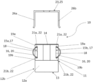
- FIG. 1 a side view of an embodiment of a cell connector system according to the invention with a counter contact element configured as a hat contact element,
- FIG. 2 a side view of a contacting of the cell connector system 10 —shown in FIG. 1 —to at least one conductor tab 24 of a single cell 33 ,
- FIG. 3 an exploded view of the embodiment of the cell connector system—shown in FIGS. 1 and 2 —,
- FIG. 4 a perspective side view of an embodiment of a storage module according to the invention with three frame devices, whereby one of the three frame devices comprises the embodiment of the cell connector system according to the invention with the counter contact element configured as a hat contact element—shown in FIGS. 1 to 3 —,
- FIG. 5 a side view of an embodiment of the electrical storage module with five frame devices, whereby the frame devices alternately each comprise the cell connector system according to the invention—shown in FIGS. 1 to 3 —with the counter contact element designed as a hat contact element,
- FIG. 6 a perspective side view of a further embodiment of the cell connector system according to the invention with a counter contact element designed as a counter contact sheet,
- FIG. 7 a perspective side view of an embodiment of a storage module according to the invention with three frame devices, whereby one of the three frame devices comprises the base contact profile of the embodiment of the cell connector system according to the invention—shown in FIG. 6 —and at least one further of the three frame devices comprises at least one counter contact element of the cell connector system designed as a counter contact sheet,
- FIG. 8 a side view of an embodiment of the electrical storage module with five frame devices, whereby the frame devices alternately each comprise a base edge profile of the cell connector system according to the invention or a counter contact element of the cell connector system designed as a counter contact sheet,
- FIG. 9 a perspective side view of a further embodiment of the cell connector system according to the invention with at least one counter contact element designed as a counter contact rail,
- FIG. 10 the embodiment of the cell connector system—shown in FIG. 9 —in a condition inserted into a frame device
- FIG. 11 a perspective side view of an embodiment of a storage module according to the invention with three frame devices, whereby one of the three frame devices comprises the base contact profile of the embodiment of the cell connector system according to the invention—shown in FIGS. 9 and 10 —and at least one further of the three frame devices comprises at least one counter contact element of the cell connector system designed as a counter contact rail.
- FIG. 1 shows a side view of an embodiment of a cell connector system 10 according to the invention with a counter contact element 23 designed as a hat contact element 25 .
- the cell connector system 10 is configured for at least one single cell (not shown in FIG. 1 ) with at least one conductor tab, whereby the single cell is insertable into an electrical storage module (not shown in FIG. 1 ) that comprises at least one frame device.
- the cell connector system 10 comprises a base contact profile 11 , whereby the base contact profile 11 includes two fronts or end surfaces 12 a , 12 b , a support surface 13 , a transition surface 14 and two mutually opposite facing contact surfaces 15 a , 15 b .
- the support surface 13 is arranged opposite the transition surface 14 , whereby the support surface 13 is configured to be placed in or on a frame device or a frame.
- the transition surface 14 is configured to ensure heat conduction to a temperature control unit by means of a thermal conducting foil (not shown in FIG. 1 ).
- the temperature control unit is optionally a cooling unit or a heating unit.
- the transition surface 14 is also configured to receive a counter contact element 23 designed as a hat contact element 25 . In the present embodiment, the transition surface 14 is configured to receive the hat contact element 25 mounted onto it.
- the base contact profile 11 comprises a mounting system 17 on each of the opposing contact surfaces 15 a , 15 b .
- the mounting system 17 comprises a receiving recess 18 , which comprises a retaining protrusion 19 a , 19 b respectively on both sides.
- the retaining protrusions 19 a , 19 b are L-shaped, whereby the receiving recess 18 with the two retaining protrusions 19 a , 19 b is configured to receive a lamella contact 16 inserted into the receiving recess 18 .
- the lamella contact 16 consists of at least one lamella 20 , which exhibits a first lamella end 21 a and a second lamella end 21 b.
- the lamella contact 16 is designed as a lamella rail, which is formed from a majority of lamellas 20 , whereby the lamellas 20 are connected to one another at their first lamella ends 21 a and at their second lamella ends 21 b .
- a respective lamella contact 16 is configured to conduct an electrical current from a conductor tab (not shown in FIG. 1 ) of an individual cell (not shown in FIG. 1 ).
- the counter contact element 23 designed as a hat contact element 25 is configured to be placeable on the base contact profile 11 with, in the present embodiment, the lamella contacts 16 being formed on both sides on a respective contact surface 15 a , 15 b of the base contact profile 11 .
- the hat contact element 25 is U-shaped, whereby the hat contact element 25 comprises a first hat end 26 a and a second hat end 26 b , whereby the hat ends 26 a , 26 b are each formed angled.
- the hat contact element 25 with the first hat end 26 a and the second hat end 26 b is configured to press a conductor tab (not shown in FIG. 1 ) of an electrical single cell onto at least one lamella contact 16 of the base contact profile 11 .
- the U-shaped hat contact element 25 can be placed in a form-fitting manner onto the base contact profile 11 and onto a conductor tab (not shown in FIG. 1 ).
- FIG. 2 shows a contacting of the cell connector system 10 —shown in FIG. 1 —on at least one conductor tab 24 of a single cell 33 .
- the cell connector system 10 is thus configured for contacting at least one single cell.
- the cell connector system 10 is arranged between two conductor tabs 24 of two single cells 33 and is thus configured for contacting two single cells 33 .
- the base contact profile 11 is arranged between the two conductor tabs 24 , whereby the counter contact element 23 designed as a hat contact element 25 is placed on the base contact profile 11 in such a way that the first hat end 26 a and the second hat end 26 b of the hat contact element 25 each press one of the conductor tabs 24 on a respective lamella contact 16 of the base contact profile 11 .
- the hat contact element 25 respectively forms an overlap area 32 with the transition surface 14 and with the conductor tabs 24 , which overlap area is configured to conduct a high-voltage current and to transport heat.
- the base contact profile 11 has the fronts or end surfaces 12 a , 12 b , the support surface 13 , the transition surface 14 and the contact surfaces 15 a , 15 b .
- each of the contact surfaces 15 a , 15 b has a mounting system 17 , which is designed as a receiving recess 18 with the retaining protrusions 19 a , 19 b and is configured to receive the respective lamella contact 16 , which is formed from at least one lamella 20 .
- the respective lamella contact 16 is configured as a lamella rail, whereby the individual lamellas 20 of the lamella rail are connected to one another respectively at a first lamella end 21 a and a second lamella end 21 b , and respectively each forms a holding surface 22 .
- FIG. 3 shows an exploded view of the embodiment of the cell connector system 10 shown in FIGS. 1 and 2 .
- the cell connector system 10 comprises the base contact profile 11 with the fronts or end surfaces 12 a , 12 b , the support surface 13 as well as the transition surface 14 with the contact surfaces 15 a , 15 b .
- a respective contact surface 15 a , 15 b exhibits a respective mounting system 17 with the receiving recess 18 and the retaining protrusions 19 a , 19 b .
- a lamella contact 16 consisting of lamellas 20 is arranged inserted into a respective receiving recess 18 , whereby the lamella contact 16 is held in the receiving recess 18 of the mounting system 17 by the retaining protrusions 19 a , 19 b .
- the retaining protrusions 19 a , 19 b are generally designed U-shaped or angled.
- FIG. 3 the counter contact element 23 designed as a hat contact element 25 is shown.
- the hat contact element 25 has the first hat end 26 a and the second hat end 26 b , whereby the first hat end 26 a and the second hat end 26 b each are designed angled.
- the hat contact element 25 is configured to be placeable onto the base contact profile 11 .
- FIG. 4 shows a perspective side view of an embodiment of a storage module according to the invention with three frame devices 29 , whereby one of the three frame devices 29 , 29 a comprises the embodiment of the cell connector system according to the invention—shown in FIGS. 1 to 3 —with the counter contact element 23 designed as a hat contact element 25 .
- the base contact profile 11 of the cell connector system 10 is designed inserted into the frame device 29 , 29 a .
- the base contact profile 11 is inserted into the frame device 29 a with the—not shown—support surface 13 .
- the contact surfaces 15 a , 15 b are each formed laterally in the direction of one of the adjacent frame devices 29 b , 29 c on the base contact profile 11 .
- the frame devices 29 alternately each exhibit the base contact profile 11 , whereby the base contact profile 11 comprises on both sides a lamella contact 16 consisting of lamellas 20 .
- the respective conductor tabs 24 of the single cells 33 are arranged between the respective frame devices 29 .
- the counter contact element 23 designed as a hat contact element 25 is respectively configured to press the respective conductor tab 24 of a single cell 33 against the respective lamella contact 16 , whereby due to the configuration as a hat contact element 25 the frame devices 29 alternately exhibit the hat contact element 25 .
- the hat contact element 25 is configured to provide contacting with the temperature control unit 35 by means of a thermal conductive foil 34 .
- the electrical storage module 40 designed in this way is configured to provide a temperature control of the single cells of the electrical storage module 40 by means of the transition surface 14 of the respective base contact profiles 11 .
- FIG. 6 shows a perspective side view of a further embodiment of the cell connector system 10 according to the invention with a counter contact element 23 designed as a counter contact sheet 27 .
- the base contact profile 11 with the support surface 13 , the transition surface 14 , the fronts i.e. end surfaces 12 a , 12 b and the contact surfaces 15 a , 15 b are shown.
- each of the contact surfaces 15 a , 15 b exhibits the mounting system 17 with the receiving recess 18 and the retaining protrusions 19 a , 19 b .
- the receiving recesses 18 each exhibit at least one lamella contact 16 consisting of lamellas 20 .
- the lamella contacts 16 exhibit holding surfaces—not shown—, which are configured to hold a respective lamella contact 16 in a respective receiving recess 18 .
- the counter contact elements 23 each designed as a counter contact sheet 27 , which are configured to be pressable onto the lamella contacts 16 of a respective receiving recess 18 when pressure is applied to the respective lamella contacts 16 by pressure goggles—not shown.
- FIG. 7 shows a perspective side view of an embodiment of a storage module 40 according to the invention with three frame devices 29 , whereby one of the three frame devices 29 comprises the base contact profile 11 of the embodiment of the cell connector system 10 according to the invention—shown in FIG. 6 —and at least one further of the three frame devices 29 comprises at least one counter contact element 23 of the cell connector system 10 designed as a counter contact sheet 27 .
- the frame device 29 a comprises the base contact profile 11 of the cell connector system 10 with the transition surface 14 and the lamella contact 16 with the lamellas 20 , which is arranged in the mounting system 17 in the receiving recess 18 .
- the frame devices 29 b , 29 c which are arranged adjacent to the frame device 29 a each exhibit a counter contact element 23 designed as a counter contact sheet 27 .
- the counter contacts sheets 27 are each respectively attached laterally opposite to a contact surface 15 a , 15 b . which is configured with a mounting system 17 , at one of the frame devices 29 b , 29 c.
- FIG. 8 shows a side view of an embodiment of the electrical storage module 40 with five frame devices 29 , whereby the frame devices 29 each alternately carry thereon either a base contact profile 11 of the cell connector system 10 according to the invention or a counter contact element 23 of the cell connector system 10 designed as a counter contact sheet 27 .
- the frame devices 29 alternately each respectively carry the base contact profile 11 or the counter contact sheet 27 , whereby the base contact profile 11 respectively comprises on both sides a lamella contact 16 consisting of lamellas 20 .
- the respective conductor tabs 24 of the single cells 33 are arranged between the respective frame devices 29 .
- the base contact profile 11 is arranged in one of the frame devices 29 , whereby the counter contact sheet 27 is arranged on at least one frame device 29 adjacent to the frame device 29 with the base contact profile 11 .
- the counter contact sheet 27 is respectively configured to press the respective conductor tab 24 of the respective single cell 33 onto the respective lamella contact 16 of the base contact profile 11 .
- the present embodiment is thus configured in such a way that a respective one of the conductor tabs 24 is respectively contacted by a lamella contact 16 and by a counter contact sheet 27 .
- FIG. 9 shows a perspective side view of a further embodiment of the cell connector system 10 according to the invention with at least one counter contact element 23 designed as a counter contact rail 28 .
- the base contact profile 11 with the support surface 13 , the transition surface 14 , the fronts i.e. end surfaces 12 a , 12 b and the contact surfaces 15 a , 15 b are shown.
- a respective one of the contact surfaces 15 a , 15 b exhibits the mounting system 17 with the receiving recess 18 and the retaining protrusions 19 a , 19 b .
- Each of the receiving recesses 18 exhibits at least one lamella contact 16 consisting of lamellas 20 .
- a respective counter contact rail 28 is configured to press on a conductor tab—not shown—, which is arranged between the counter contact rail 28 and a lamella contact 16 of a receiving recess 18 of a base contact profile 11 .
- a respective counter contact rail 28 has a mounting system 17 with a receiving recess 18 and retaining protrusions 19 a , 19 b , whereby the receiving recess 18 receives at least one lamella contact 16 with lamellas 20 .
- the receiving recess 18 receives at least one lamella contact 16 with lamellas 20 .
- FIG. 10 shows the embodiment of the cell connector system 10 —shown in FIG. 9 —in a state inserted into a frame device 29 a .
- the frame device 29 a comprises the base contact profile 11 of the cell connector system 10 with the transition surface 14 and the lamella contact 16 with the lamellas 20 , which is arranged in the mounting system 17 in the receiving recess 18 .
- the frame devices 29 b , 29 c arranged adjacent to the frame device 29 a each exhibits a counter contact element 23 designed as a counter contact rail 28 .
- the counter contact rails 28 are each attached laterally opposite to a contact surface 15 a , 15 b configured with a mounting system 17 on one of the frame devices 29 b , 29 c.
- the counter contact rails 28 each exhibit a mounting system 17 with a receiving recess 18 and retaining protrusions 19 a , 19 b , whereby the receiving recess 18 is configured to receive at least one lamella contact 16 .
- a respective counter contact rail 28 is configured to press on a conductor tab—not shown here—arranged between the counter contact rail 28 and a lamella contact 16 of a receiving recess 18 of a base contact profile 11 .
- FIG. 11 shows a perspective side view of an embodiment of the storage module 40 according to the invention with three frame devices 29 , whereby one of the three frame devices 29 comprises the base contact profile of the embodiment of the cell connector system 10 according to the invention—shown in FIGS. 9 and 10 —, and at least one further of the three frame devices 29 comprises at least one counter contact element of the cell connector system designed as a counter contact rail 28 .
- the frame device 29 a comprises the base contact profile 11 of the cell connector system 10 with the transition surface 14 and the lamella contact 16 with the lamellas 20 , which is arranged in the mounting system 17 in the receiving recess 18 .
- the frame devices 29 b , 29 c arranged adjacent to the frame device 29 a each exhibit two counter contact elements 23 designed as counter contact rails 28 .
- the counter contact rails 28 are each attached laterally opposite to a contact surface 15 a , 15 b configured with a mounting system 17 on one of the frame devices 29 b , 29 c.
- the counter contact rails 28 each exhibit the mounting system 17 with the receiving recess 18 and the retaining protrusions 19 a , 19 b , whereby the respective receiving recess 18 is configured to receive at least one lamella contact 16 .
- the respective counter contact rail 28 is configured to press on a conductor tab—not shown here—arranged between the counter contact rail 28 and the lamella contact 16 of the base contact profile 11 .
- the base contact profile 11 is formed tapered toward the transition surface 14
- the hat contact element 25 is formed tapered to correspond to the base contact profile 11 .
- the receiving recess 18 comprises two dovetail-like recesses, each formed in the area of one of the retaining protrusions 19 a , 19 b and at an angle between 100° and 150°, in particular between 101° and 120°, to a respective contact surface 15 a , 15 b of the base contact profile 11 .
Landscapes
- Chemical & Material Sciences (AREA)
- Chemical Kinetics & Catalysis (AREA)
- Electrochemistry (AREA)
- General Chemical & Material Sciences (AREA)
- Connector Housings Or Holding Contact Members (AREA)
Abstract
Description
-
- 10 cell connector system
- 11 base contact profile
- 12 a, 12 b fronts or end surfaces
- 13 support surface
- 14 transition surface
- 15 a, 15 b contact surfaces
- 16 lamella contact
- 17 mounting system
- 18 receiving recess
- 19 a, 19 b retaining protrusions
- 20 lamellas
- 21 a, 21 b first end, second end of a lamella
- 22 holding surfaces
- 23 counter contact element
- 24 conductor tab
- 25 hat contact element
- 26 a, 26 b first hat end, second hat end
- 27 counter contact sheet
- 27 a, 27 b first and second leg of a counter contact sheet
- 28 counter contact rail
- 29 frame device
- 29 a, 29 b first and second frame devices
- 30 side surface face of a second frame device
- 32 overlap area
- 33 single cell
- 34 thermal conductive foil
- 35 temperature control unit
- 40 electrical storage module
Claims (19)
Applications Claiming Priority (2)
| Application Number | Priority Date | Filing Date | Title |
|---|---|---|---|
| DE102020117664.3 | 2020-07-03 | ||
| DE102020117664.3A DE102020117664A1 (en) | 2020-07-03 | 2020-07-03 | Cell connector system for a single cell |
Publications (2)
| Publication Number | Publication Date |
|---|---|
| US20220006153A1 US20220006153A1 (en) | 2022-01-06 |
| US12113230B2 true US12113230B2 (en) | 2024-10-08 |
Family
ID=79019686
Family Applications (1)
| Application Number | Title | Priority Date | Filing Date |
|---|---|---|---|
| US17/348,132 Active 2043-03-02 US12113230B2 (en) | 2020-07-03 | 2021-06-15 | Cell connector system for a single cell |
Country Status (2)
| Country | Link |
|---|---|
| US (1) | US12113230B2 (en) |
| DE (1) | DE102020117664A1 (en) |
Citations (5)
| Publication number | Priority date | Publication date | Assignee | Title |
|---|---|---|---|---|
| DE102009013727A1 (en) | 2009-03-20 | 2010-09-30 | Clean Mobile Ag | Battery e.g. lithium ion battery, for use in e.g. electric vehicle, has spring provided for pressing electrode connections of flat cells on electrically conducting connecting piece for two flat cells that lie on top of each other |
| DE102011109194A1 (en) | 2010-08-10 | 2012-02-16 | Gm Global Technology Operations Llc (N.D.Ges.D. Staates Delaware) | Integrated stackable battery |
| DE102011103991A1 (en) | 2011-06-10 | 2012-12-13 | Daimler Ag | Battery mounted in e.g. electric vehicle, has spring element which is arranged between contact pins of unit battery cells and cell connector, so as to counteract force applied by clamping force |
| DE102012018037A1 (en) | 2012-09-13 | 2014-03-13 | Daimler Ag | Battery e.g. lithium-ion traction battery for e.g. electric car, has slats that are arranged in slat support of cell frame and extended transversely to stacking direction, and films whose edge region is clamped between frame portions |
| DE102012018088A1 (en) | 2012-09-13 | 2014-03-13 | Daimler Ag | Device for electrical contacting of prismatic unit battery cells in stack of individual battery cells, has resilient electrically connecting element that is arranged between contact lugs via pressing element |
-
2020
- 2020-07-03 DE DE102020117664.3A patent/DE102020117664A1/en active Pending
-
2021
- 2021-06-15 US US17/348,132 patent/US12113230B2/en active Active
Patent Citations (6)
| Publication number | Priority date | Publication date | Assignee | Title |
|---|---|---|---|---|
| DE102009013727A1 (en) | 2009-03-20 | 2010-09-30 | Clean Mobile Ag | Battery e.g. lithium ion battery, for use in e.g. electric vehicle, has spring provided for pressing electrode connections of flat cells on electrically conducting connecting piece for two flat cells that lie on top of each other |
| DE102011109194A1 (en) | 2010-08-10 | 2012-02-16 | Gm Global Technology Operations Llc (N.D.Ges.D. Staates Delaware) | Integrated stackable battery |
| US9385360B2 (en) | 2010-08-10 | 2016-07-05 | GM Global Technology Operations LLC | Integrated stackable battery |
| DE102011103991A1 (en) | 2011-06-10 | 2012-12-13 | Daimler Ag | Battery mounted in e.g. electric vehicle, has spring element which is arranged between contact pins of unit battery cells and cell connector, so as to counteract force applied by clamping force |
| DE102012018037A1 (en) | 2012-09-13 | 2014-03-13 | Daimler Ag | Battery e.g. lithium-ion traction battery for e.g. electric car, has slats that are arranged in slat support of cell frame and extended transversely to stacking direction, and films whose edge region is clamped between frame portions |
| DE102012018088A1 (en) | 2012-09-13 | 2014-03-13 | Daimler Ag | Device for electrical contacting of prismatic unit battery cells in stack of individual battery cells, has resilient electrically connecting element that is arranged between contact lugs via pressing element |
Non-Patent Citations (1)
| Title |
|---|
| German Office Action issued Apr. 28, 2021 in German Patent Application No. 10 2002 117 664.3, 9 pages, with English partial translation, 8 pages. |
Also Published As
| Publication number | Publication date |
|---|---|
| DE102020117664A1 (en) | 2022-01-05 |
| US20220006153A1 (en) | 2022-01-06 |
Similar Documents
| Publication | Publication Date | Title |
|---|---|---|
| US11380948B2 (en) | Battery module | |
| JP6411742B2 (en) | Battery module | |
| EP2357689A1 (en) | Battery module | |
| EP3855554A1 (en) | Battery pack | |
| CN101388442B (en) | System and method for electrically connecting terminals of a battery | |
| US10347895B2 (en) | Conductive member module and battery pack | |
| EP3255703B1 (en) | Battery pack | |
| US20200013997A1 (en) | Battery pack | |
| JP6926630B2 (en) | Battery module | |
| JP5991044B2 (en) | Battery module | |
| JP4712929B2 (en) | Abnormal temperature detection device for battery pack | |
| JP2022159153A (en) | Battery pack temperature acquisition modules and systems | |
| US20160233601A1 (en) | Header, receptacle, connector, and method of manufacturing the header | |
| CN114051673A (en) | Electricity storage group | |
| US12113230B2 (en) | Cell connector system for a single cell | |
| KR20150056585A (en) | Electrical storage module | |
| US20220278428A1 (en) | Connection Member Connected to Electrode Leads by Physical Coupling and Battery Cell Stack Including the Same | |
| US9490556B2 (en) | Cell contacting arrangement for an energy storage device | |
| CN112992866A (en) | Current bypass structure and IGBT device | |
| KR101968717B1 (en) | Method for connecting first and second electrical terminals of first and second battery cells to a voltage sensing member of a battery module and interconnect assembly | |
| US7845991B2 (en) | Apparatus for the electrical connection of cell arresters | |
| JP2020107400A (en) | Bus bar fastening structure | |
| CN108695479B (en) | Device and method for holding an electrical circuit against a battery module | |
| CN113767519B (en) | Voltage detection line components | |
| JP3988749B2 (en) | Electric heater |
Legal Events
| Date | Code | Title | Description |
|---|---|---|---|
| AS | Assignment |
Owner name: TEKESER, HANS MARTIN, GERMANY Free format text: ASSIGNMENT OF ASSIGNORS INTEREST;ASSIGNOR:JOHNSON, TORSTEN;REEL/FRAME:056550/0497 Effective date: 20210531 |
|
| FEPP | Fee payment procedure |
Free format text: ENTITY STATUS SET TO UNDISCOUNTED (ORIGINAL EVENT CODE: BIG.); ENTITY STATUS OF PATENT OWNER: SMALL ENTITY |
|
| FEPP | Fee payment procedure |
Free format text: ENTITY STATUS SET TO SMALL (ORIGINAL EVENT CODE: SMAL); ENTITY STATUS OF PATENT OWNER: SMALL ENTITY |
|
| STPP | Information on status: patent application and granting procedure in general |
Free format text: DOCKETED NEW CASE - READY FOR EXAMINATION |
|
| AS | Assignment |
Owner name: DHST HOLDING GMBH & CO. KG, GERMANY Free format text: MERGER;ASSIGNOR:TEKESER, HANS MARTIN;REEL/FRAME:065306/0648 Effective date: 20221208 |
|
| STPP | Information on status: patent application and granting procedure in general |
Free format text: NON FINAL ACTION COUNTED, NOT YET MAILED |
|
| STPP | Information on status: patent application and granting procedure in general |
Free format text: NON FINAL ACTION MAILED |
|
| STPP | Information on status: patent application and granting procedure in general |
Free format text: RESPONSE TO NON-FINAL OFFICE ACTION ENTERED AND FORWARDED TO EXAMINER |
|
| STPP | Information on status: patent application and granting procedure in general |
Free format text: NOTICE OF ALLOWANCE MAILED -- APPLICATION RECEIVED IN OFFICE OF PUBLICATIONS |
|
| ZAAB | Notice of allowance mailed |
Free format text: ORIGINAL CODE: MN/=. |
|
| STPP | Information on status: patent application and granting procedure in general |
Free format text: PUBLICATIONS -- ISSUE FEE PAYMENT RECEIVED |
|
| STPP | Information on status: patent application and granting procedure in general |
Free format text: PUBLICATIONS -- ISSUE FEE PAYMENT VERIFIED |
|
| STCF | Information on status: patent grant |
Free format text: PATENTED CASE |