US12110654B2 - Excavation data processing method, excavation data processing device, and excavator for trench - Google Patents
Excavation data processing method, excavation data processing device, and excavator for trench Download PDFInfo
- Publication number
- US12110654B2 US12110654B2 US16/920,851 US202016920851A US12110654B2 US 12110654 B2 US12110654 B2 US 12110654B2 US 202016920851 A US202016920851 A US 202016920851A US 12110654 B2 US12110654 B2 US 12110654B2
- Authority
- US
- United States
- Prior art keywords
- excavation
- data
- trench
- positions
- excavating
- Prior art date
- Legal status (The legal status is an assumption and is not a legal conclusion. Google has not performed a legal analysis and makes no representation as to the accuracy of the status listed.)
- Active, expires
Links
- 238000009412 basement excavation Methods 0.000 title claims abstract description 242
- 238000012545 processing Methods 0.000 title claims abstract description 125
- 238000003672 processing method Methods 0.000 title abstract description 16
- 238000005259 measurement Methods 0.000 claims abstract description 64
- 238000010586 diagram Methods 0.000 claims description 59
- 238000001514 detection method Methods 0.000 claims description 54
- 238000009826 distribution Methods 0.000 claims description 53
- 238000000034 method Methods 0.000 description 16
- 238000003860 storage Methods 0.000 description 15
- 238000004891 communication Methods 0.000 description 9
- 239000007788 liquid Substances 0.000 description 7
- 238000006243 chemical reaction Methods 0.000 description 6
- 239000002689 soil Substances 0.000 description 5
- 238000003756 stirring Methods 0.000 description 4
- QNRATNLHPGXHMA-XZHTYLCXSA-N (r)-(6-ethoxyquinolin-4-yl)-[(2s,4s,5r)-5-ethyl-1-azabicyclo[2.2.2]octan-2-yl]methanol;hydrochloride Chemical compound Cl.C([C@H]([C@H](C1)CC)C2)CN1[C@@H]2[C@H](O)C1=CC=NC2=CC=C(OCC)C=C21 QNRATNLHPGXHMA-XZHTYLCXSA-N 0.000 description 3
- 238000004590 computer program Methods 0.000 description 3
- 238000010276 construction Methods 0.000 description 3
- 230000003028 elevating effect Effects 0.000 description 3
- 239000004568 cement Substances 0.000 description 2
- 238000012986 modification Methods 0.000 description 2
- 230000004048 modification Effects 0.000 description 2
- 238000012544 monitoring process Methods 0.000 description 2
- 230000002093 peripheral effect Effects 0.000 description 2
- 238000009825 accumulation Methods 0.000 description 1
- 230000005540 biological transmission Effects 0.000 description 1
- 238000009795 derivation Methods 0.000 description 1
- 230000000694 effects Effects 0.000 description 1
- 238000010348 incorporation Methods 0.000 description 1
- 239000007787 solid Substances 0.000 description 1
- 238000007711 solidification Methods 0.000 description 1
- 230000008023 solidification Effects 0.000 description 1
Images


Classifications
-
- E—FIXED CONSTRUCTIONS
- E02—HYDRAULIC ENGINEERING; FOUNDATIONS; SOIL SHIFTING
- E02F—DREDGING; SOIL-SHIFTING
- E02F5/00—Dredgers or soil-shifting machines for special purposes
- E02F5/02—Dredgers or soil-shifting machines for special purposes for digging trenches or ditches
- E02F5/14—Component parts for trench excavators, e.g. indicating devices travelling gear chassis, supports, skids
- E02F5/145—Component parts for trench excavators, e.g. indicating devices travelling gear chassis, supports, skids control and indicating devices
-
- E—FIXED CONSTRUCTIONS
- E02—HYDRAULIC ENGINEERING; FOUNDATIONS; SOIL SHIFTING
- E02F—DREDGING; SOIL-SHIFTING
- E02F5/00—Dredgers or soil-shifting machines for special purposes
- E02F5/02—Dredgers or soil-shifting machines for special purposes for digging trenches or ditches
- E02F5/06—Dredgers or soil-shifting machines for special purposes for digging trenches or ditches with digging elements mounted on an endless chain
-
- E—FIXED CONSTRUCTIONS
- E02—HYDRAULIC ENGINEERING; FOUNDATIONS; SOIL SHIFTING
- E02F—DREDGING; SOIL-SHIFTING
- E02F9/00—Component parts of dredgers or soil-shifting machines, not restricted to one of the kinds covered by groups E02F3/00 - E02F7/00
- E02F9/26—Indicating devices
- E02F9/264—Sensors and their calibration for indicating the position of the work tool
-
- G—PHYSICS
- G01—MEASURING; TESTING
- G01B—MEASURING LENGTH, THICKNESS OR SIMILAR LINEAR DIMENSIONS; MEASURING ANGLES; MEASURING AREAS; MEASURING IRREGULARITIES OF SURFACES OR CONTOURS
- G01B21/00—Measuring arrangements or details thereof, where the measuring technique is not covered by the other groups of this subclass, unspecified or not relevant
- G01B21/20—Measuring arrangements or details thereof, where the measuring technique is not covered by the other groups of this subclass, unspecified or not relevant for measuring contours or curvatures, e.g. determining profile
-
- G—PHYSICS
- G01—MEASURING; TESTING
- G01B—MEASURING LENGTH, THICKNESS OR SIMILAR LINEAR DIMENSIONS; MEASURING ANGLES; MEASURING AREAS; MEASURING IRREGULARITIES OF SURFACES OR CONTOURS
- G01B7/00—Measuring arrangements characterised by the use of electric or magnetic techniques
- G01B7/28—Measuring arrangements characterised by the use of electric or magnetic techniques for measuring contours or curvatures
-
- G—PHYSICS
- G01—MEASURING; TESTING
- G01C—MEASURING DISTANCES, LEVELS OR BEARINGS; SURVEYING; NAVIGATION; GYROSCOPIC INSTRUMENTS; PHOTOGRAMMETRY OR VIDEOGRAMMETRY
- G01C9/00—Measuring inclination, e.g. by clinometers, by levels
- G01C9/02—Details
-
- G—PHYSICS
- G01—MEASURING; TESTING
- G01C—MEASURING DISTANCES, LEVELS OR BEARINGS; SURVEYING; NAVIGATION; GYROSCOPIC INSTRUMENTS; PHOTOGRAMMETRY OR VIDEOGRAMMETRY
- G01C7/00—Tracing profiles
- G01C7/06—Tracing profiles of cavities, e.g. tunnels
Definitions
- the present invention relates to an excavation data processing method of deriving a value related to a shape of a trench in a case where the trench is excavated by moving an excavating body having an excavating chain in a vertical direction and a lateral direction, and to an excavation data processing device and an excavator for a trench.
- TRD Treatment Re-mixing Deep Wall Method
- An excavator for a trench for use in the TRD is provided with an excavating body having a vertically long post portion and an endless excavating chain which rotates along a periphery of the post portion.
- the excavator for a trench excavates a trench by moving, in a lateral direction, the excavating body being partly buried underground. Further, the excavator for a trench creates a wall by stirring and mixing soil and a solidifying liquid in the trench.
- a temporary wall which prevents a landslide in a process of work, such as an earth retaining wall, or a permanent wall.
- the permanent wall is a wall of a construction itself.
- the earth retaining wall is referred to as a land slide protection wall or a land slide protection in some cases.
- the trench is formed from the ground surface down to a position deeper than a depth of an underground excavation bottom. Then, after the wall in which filling the trench is created and before a building is constructed, a part of the land on one side of the wall is excavated down to the depth of the excavation bottom.
- a shape of the wall at a position of the depth of the excavation bottom is in particular essential.
- a shape of the wall is substantially the same as the shape of the trench.
- the clinometer in the excavating body is not always arranged at a position of the depth of the excavation bottom.
- An object of the present invention is to provide an excavation data processing method which enables derivation of a shape value of a trench at a position of a depth of an excavation bottom in a case where the trench is excavated by the TRD, irrespective of a position of a part of an excavating body where an inclination angle is detected, and an excavation data processing device and an excavator for a trench therefor.
- the present invention provides an excavation data processing method.
- the excavation data processing method is for acquiring data output from an excavator for a trench that, while excavating a trench underground by moving, in a lateral direction, an excavating body being partly buried underground, forms a wall underground corresponding to the trench, the excavating body having a vertically long post portion extending in an up-down direction and having an endless excavating chain supported by the post portion so as to surround the post portion in the up-down direction and the lateral direction and rotating along a periphery of the post portion, and for deriving information related to a shape of the trench in order to excavate a part adjacent to one wall surface of the wall extending in the lateral direction, down to a predetermined excavation bottom positioned between an upper end portion and a lower end portion of the wall.
- the excavation data processing method includes: a first acquisition step of acquiring reference part position data as data related to a relative position of a reference part of the excavating body with respect to an origin on the ground surface, the reference part being arranged above the ground; data of a plurality of measuring part positions as data related to a relative position of each of a plurality of measuring parts in the excavating body with respect to the reference part, the plurality of measuring parts being arranged underground at a space from each other in the up-down direction; and data indicative of an excavation depth as a depth from the ground surface to the excavation bottom underground; a second acquisition step of acquiring data of a plurality of inclination angle as data of an inclination angle of each of the plurality of measuring parts, the data being output from the excavator for a trench; a first deriving step of deriving a plurality of measurement positions as relative positions of the plurality of measuring parts with respect to the origin from the reference part position data and the plurality of measuring part positions data acquired in the first acquisition step and the plurality
- the present invention also provides an excavation data processing device.
- the excavation data processing device acquires data output from an excavator for a trench that, while excavating a trench underground by moving, in a lateral direction, an excavating body being partly buried underground, forms a wall underground corresponding to the trench, the excavating body having a vertically long post portion extending in an up-down direction and having an endless excavating chain supported by the post portion so as to surround the post portion in the up-down direction and the lateral direction and rotating along a periphery of the post portion, and derives information related to a shape of the trench in order to excavate a part adjacent to one wall surface of the wall extending in the lateral direction, down to a predetermined excavation bottom positioned between an upper end portion and a lower end portion of the wall.
- the excavation data processing device includes: a first acquisition portion which acquires reference part position data as data related to a relative position of a reference part of the excavating body with respect to an origin on the ground surface, the reference part being arranged above the ground; data of a plurality of measuring part positions as data related to a relative position of each of a plurality of measuring parts in the excavating body with respect to the reference part, the plurality of measuring parts being arranged underground at a space from each other in the up-down direction; and data indicative of an excavation depth as a depth from the ground surface to the excavation bottom underground; a second acquisition portion which acquires data of a plurality of inclination angles as data of an inclination angle of each of the plurality of measuring parts, the data being output from the excavator for a trench; a first deriving portion which derives a plurality of measurement positions as relative positions of the plurality of measuring parts with respect to the origin from the reference part position data and the plurality of measuring part positions data acquired by the first acquisition portion and the plurality of
- the present invention further provides an excavator for a trench.
- the excavator for a trench includes: an excavating body having a vertically long post portion extending in an up-down direction and having an endless excavating chain supported by the post portion so as to surround the post portion in the up-down direction and a lateral direction and rotating along a periphery of the post portion; an inclination angle detection device which detects and outputs an inclination angle of each of a plurality of measuring parts arranged at a space from each other in the up-down direction in the excavating body; and the above-described excavation data processing device.
- the excavating body While moving in the lateral direction to excavate a trench underground, the excavating body being partly buried underground forms a wall underground corresponding to the trench, and the excavation data processing device acquires data of the plurality of inclination angle detection values from the inclination angle detection device to derive information related to a shape of the trench.
- FIG. 1 is a front view of an excavator for a trench according to a first embodiment of the present invention
- FIG. 2 is a side view of the excavator for a trench according to the first embodiment of the present invention
- FIG. 3 is a block diagram showing a configuration of a data processing related apparatus in the excavator for a trench according to the first embodiment of the present invention
- FIG. 5 is a flow chart showing one example of a procedure of excavation data processing executed in the excavator for a trench according to the first embodiment of the present invention
- FIG. 7 is an output image of a second excavation result output by the data processing device in the excavator for a trench according to the first embodiment of the present invention.
- FIG. 8 is an output image of a third excavation result output by the data processing device in the excavator for a trench according to the first embodiment of the present invention.
- FIG. 9 is an output image of a fourth excavation result output by the data processing device in the excavator for a trench according to the first embodiment of the present invention.
- FIG. 1 is a front view of the excavator for a trench 10 according to the present embodiment and FIG. 2 is a side view of the excavator for a trench.
- the excavator for a trench 10 is a working machine for use in the TRD which is one of the soil cement underground continuous wall construction methods.
- the excavator for a trench 10 excavates a trench forming an outer shape of a wall.
- the wall is, for example, an earth retaining wall or a permanent wall.
- the excavator for a trench 10 creates the wall by stirring and mixing soil and a solidifying liquid in the trench excavated.
- the excavator for a trench 10 includes a main body portion 11 , a portal frame 12 , a leader 13 , an excavating body 14 , a slide actuator 15 , an elevating actuator 16 , a stay actuator 17 , and the like.
- the excavator for a trench 10 also includes a travelling device 11 a and a cab 11 b linked to the main body portion 11 .
- the travelling device 11 a travels on the ground surface to cause the main body portion 11 to move along the ground surface.
- the portal frame 12 is turnably supported by the main body portion 11 .
- the stay actuator 17 links the main body portion 11 and the portal frame 12 and adjusts an angle of the portal frame 12 with respect to a vertical direction.
- the leader 13 is supported by the portal frame 12 so as to be slidable in a lateral direction.
- the slide actuator 15 causes the leader 13 to move in the lateral direction.
- the excavation base portion 140 is supported by the leader 13 so as to be movable in an up-down direction.
- the elevating actuator 16 causes the excavation base portion 140 to move in the up-down direction.
- the excavation base portion 140 contains the drive sprocket 143 and the chain drive motor 145 .
- the drive sprocket 143 is rotatably supported by the excavation base portion 140 .
- the cutter post 141 is linked with a lower portion of the excavation base portion 140 and is formed to be vertically long so as to extend in the up-down direction.
- the cutter post 141 is configured with a plurality of unit posts 1410 linked in the vertical direction.
- the driven sprocket 144 is rotatably supported by a lower end portion of the cutter post 141 .
- the cutter post 141 is one example of a post portion supporting the endless excavating chain 142 .
- the first direction D 1 is a depth direction of the trench, i.e. a depth direction of the wall.
- the first direction D 1 is a vertically downward direction.
- the first direction D 1 may be an obliquely downward direction which forms a predetermined angle with respect to the vertical direction in some cases.
- the stay actuator 17 adjusts an angle of the excavating body 14 so that a longitudinal direction of the excavating body 14 goes along the first direction D 1 .
- the slide actuator 15 causes the excavating body 14 to move in a second direction D 2 orthogonal to the first direction D 1 .
- the second direction D 2 is a length direction of the trench, i.e., a length direction of the wall, and is a horizontal direction.
- a lateral moving direction of the excavating body 14 caused by the slide actuator 15 includes the second direction D 2 and a direction oppopart to the second direction D 2 .
- the slide actuator 15 causes the excavating body 14 to move so as to return to a start point of the movable range in the lateral direction. Further, the travelling device 11 a causes the excavator for a trench 10 including the excavating body 14 as a whole to move in the second direction D 2 .
- Movement of the excavating body 14 in the second direction D 2 caused by the slide actuator 15 or the travelling device 11 a will be repeated until the excavating body 14 moves from a leading edge position to a terminal edge position of the trench in the second direction D 2 .
- the excavator for a trench 10 excavates the trench forming the outer shape of the wall by causing the excavating body 14 to move from the ground surface in the first direction D 1 (the downward direction) and further causes the excavating body 14 to move in the second direction D 2 (the lateral direction) while causing the excavating chain 142 to rotate.
- a third direction D 3 shown in FIGS. 1 and 2 is a horizontal direction orthogonal to the second direction D 2 .
- the third direction D 3 is a direction heading from the main body portion 11 side toward a side oppopart to the main body portion 11 with respect to the excavating body 14 .
- the excavator for a trench 10 discharges a solidifying liquid from the cutter post 141 .
- the wall having the shape of the trench as an outer shape is formed underground.
- FIG. 3 is a block diagram showing a configuration of a data processing related apparatus in the excavator for a trench 10 according to the present embodiment.
- the excavator for a trench 10 is provided with a state detection device 4 , a data processing device 5 , and peripheral devices of the data processing device 5 .
- the peripheral devices include an operation input device 61 , a display device 62 , an AD conversion device 63 , a storage device 64 , a radio communication device 65 , and the like.
- the data processing device 5 the operation input device 61 , the display device 62 , and the storage device 64 are arranged in the cab 11 b.
- the state detection device 4 detects various kinds of states of the excavator for a trench 10 .
- the state detection device 4 includes a travel distance sensor 41 , a stroke sensor 42 , a cutter load sensor 43 , a plurality of clinometers 44 , and the like.
- a detection signal output from the state detection device 4 is converted into digital data by the AD conversion device 63 and the converted data is transmitted to the data processing device 5 .
- the travel distance sensor 41 measures a moving distance, in the second direction D 2 , of the excavator for a trench 10 which travels by the operation of the travelling device 11 a .
- the AD conversion device 63 converts a detection signal of the travel distance sensor 41 into data of a travel distance detection value and outputs the data of the travel distance detection value to the data processing device 5 .
- the stroke sensor 42 measures a moving distance, in the second direction D 2 , of the excavating body 14 which moves by the operation of the slide actuator 15 .
- the AD conversion device 63 converts a detection signal of the stroke sensor 42 into data of a lateral slide distance detection value and outputs the data of the lateral slide distance detection value to the data processing device 5 .
- a total of the travel distance detection value and the lateral slide distance detection value is a moving distance of the excavating body 14 in the second direction D 2 .
- Each of the data of the travel distance detection value and the data of the lateral slide distance detection value is one example of data indicative of a moving distance of the excavating body 14 in the second direction D 2 .
- the cutter load sensor 43 detects a load to be applied to the chain drive motor 145 , i.e., a load to be applied to the excavating chain 142 .
- a load detected by the cutter load sensor 43 is used as an index of a solidification condition of the solidifying liquid when operation of the excavating chain 142 which stirs the solidifying liquid is controlled.
- the plurality of clinometers 44 is arranged at different positions in the cutter post 141 .
- the plurality of clinometers 44 detects an inclination angle of each of a plurality of longitudinal measuring parts of the excavating body 14 with respect to a reference direction.
- an angle detected by each clinometer 44 is an angle of inclination of each measuring part with respect to a vertical line (a reference direction) when each measuring part is viewed from the second direction D 2 .
- an inclination angle detected by each clinometer 44 is an angle of inclination in the third direction D 3 of each measuring part with respect to the vertical line.
- the first direction D 1 is the obliquely downward direction which forms a predetermined angle with respect to the vertical direction as described above
- an inclination angle detected by each clinometer 44 corresponds to an inclination angle of the measuring part with respect to the first direction D 1 .
- the plurality of clinometers 44 includes one ground clinometer 44 a and a plurality of underground clinometers 44 b .
- the ground clinometer 44 a is arranged at a part positioned above the ground surface among the plurality of measuring parts.
- the plurality of underground clinometers 44 b is arranged at a plurality of parts positioned underground among the plurality of measuring parts.
- the AD conversion device 63 converts a detection signal of the plurality of clinometers 44 into data of a plurality of inclination angle detection values and outputs the data of the plurality of inclination angle detection values to the data processing device 5 .
- Each of the plurality of clinometers 44 and the AD conversion device 63 is one example of an inclination angle detection device.
- the operation input device 61 is a device which inputs information according to person's operation and includes, for example, a keyboard, a touch panel, or the like.
- the display device 62 is a device which displays information, and is, for example, a panel display device such as a liquid display panel.
- the storage device 64 is a nonvolatile storage device which stores various kinds of data to be referred to or recorded by the data processing device 5 .
- an SSD Solid State Drive
- a hard disk drive is adopted as the storage device 64 .
- the radio communication device 65 is a communication interface device which communicates with a management device not shown through a radio communication network.
- the data processing device 5 is communicable with the management device connected to the Internet through the radio communication device 65 .
- FIG. 4 is a block diagram showing a configuration of the data processing device 5 (an excavation data processing device) in the excavator for a trench 10 according to the present embodiment.
- the data processing device 5 is provided with a CPU (Central Processing Unit) 51 , a RAM (Random Access Memory) 52 , a bus interface 53 , and the like.
- the CPU 51 is a processor which executes various kinds of data processing by executing a computer program stored in the storage device 64 .
- the RAM 52 is a volatile memory which primarily stores the computer program to be executed by the CPU 51 and data to be referred to or recorded by the CPU 51 .
- the bus interface 53 is an interface device which relays data transmission and reception between the CPU 51 and the operation input device 61 , the display device 62 , the storage device 64 , and the radio communication device 65 through buses.
- the data processing device 5 acquires data of a plurality of detection values output from the state detection device 4 of the excavator for a trench 10 and derives a value (information) related to the shape of the trench from each detection value.
- the data processing device 5 is one example of an excavation data processing device.
- the plurality of detection values includes the travel distance detection value, the lateral slide distance detection value, and the inclination angle detection values of the plurality of measuring parts.
- the trench is formed from the ground surface down to a position deeper than a depth of an underground excavation bottom. Then, after the wall filling the trench is created and before a building is constructed, a part of the land on one side of the wall is excavated down to the depth of the excavation bottom.
- the excavation bottom here is not a bottom of a trench formed by an excavator for a trench but a bottom portion of a trench excavated later adjacent to the wall formed by the excavator for a trench. The bottom portion in many cases becomes a foundation part of a building.
- An excavation bottom is set below an upper end portion of a trench (wall) formed by an excavator for a trench, i.e., is set below the ground surface and above a lower end portion of the trench (wall) formed by the excavator for a trench.
- a shape of the trench at a position of the depth of the excavation bottom is in particular essential.
- a shape of the wall is substantially the same as the shape of the trench.
- the plurality of clinometers 44 in the excavating body 14 is not always arranged at a position of the depth of the excavation bottom.
- the data processing device 5 executes excavation data processing to be described later (see FIG. 5 ). This enables the data processing device 5 to derive a shape value of the trench at the position of the depth of the excavation bottom irrespective of a position of the plurality of measuring parts at which an inclination angle is detected in the excavating body 14 .
- FIG. 5 is a flow chart showing one example of a procedure of excavation data processing executed in the excavator for a trench 10 according to the present embodiment.
- description will be made of one example of a procedure of the excavation data processing executed by the data processing device 5 .
- Execution of the excavation data processing realizes an excavation data processing method according to the present invention.
- the data processing device 5 includes a plurality of processing modules realized by the execution of the computer program by the CPU 51 .
- the plurality of processing modules executes the excavation data processing.
- the plurality of processing modules includes a main control portion 5 a , a data acquiring portion 5 b , a measurement position deriving portion 5 c , an interpolation processing portion 5 d , a gap deriving portion 5 e , and an output portion 5 f (also referred to as a data input portion) (see FIG. 3 ).
- the main control portion 5 a causes the excavation data processing to start.
- the excavating body 14 starts moving in the second direction D 2 after the excavator for a trench 10 finishes with excavation of a hole in the first direction D 1 at a point where excavation of the trench is started, the start operation is conducted.
- S 1 , S 2 . . . represent identification codes indicative of a plurality of steps in the excavation data processing.
- Step S 1 the data acquiring portion 5 b acquires basic data DT 1 through the operation input device 61 or from the storage device 64 .
- FIG. 3 shows an example in which the basic data DT 1 is stored in the storage device 64 in advance.
- the basic data DT 1 includes data of a position of a ground clinometer, data of a position of a plurality of underground clinometers, data of a wall thickness, data of an excavation depth, and data of one or more designated positions.
- the wall thickness is a thickness of the wall formed underground and is also a thickness of the trench.
- the wall thickness corresponds to a thickness of a part of the excavating body 14 which enters the underground.
- the position of the ground clinometer is represented by a distance from an intersection between the excavating body 14 and the ground surface to the ground clinometer 44 a at a point where excavation of the trench is started, in other words, before the excavator for a trench 10 starts travelling.
- the intersection between the excavating body 14 and the ground surface is an origin on the ground surface as a reference for various kinds of positions.
- a detected angle of the ground clinometer 44 a is defined as (pa and a value of a position of the ground clinometer is defined as La
- a coordinate Ya in the third direction D 3 and a coordinate Za in the vertical direction at the position of the ground clinometer 44 a on the basis of the origin are respectively represented by Formula (1) below.
- a part at which the ground clinometer 44 a is arranged in the excavating body 14 is a reference part.
- the data of a position of the ground clinometer is one example of data (reference part position data) indicative of a relative position of the reference part with respect to the origin.
- the part at which the ground clinometer 44 a is arranged in the excavating body 14 is also one of the plurality of measuring parts.
- the reference part position data may be absolute position data.
- a position of the plurality of underground clinometers is represented by a distance from the ground clinometer 44 a to each of the plurality of underground clinometers 44 b .
- Data of a position of the plurality of underground clinometers is one example of data (data of the plurality of measuring part positions) indicative of a relative position of the plurality of measuring parts with respect to the reference part.
- the data of the plurality of measuring part positions may be absolute position data.
- a detected angle of the underground clinometer 44 b is defined as ⁇ b and a value of a position of the underground clinometer is defined as Lb
- a coordinate Yb in the third direction D 3 and a coordinate Zb in the vertical direction at the position of the underground clinometer 44 b on the basis of the origin are respectively represented by Formula (2) below.
- Yb Lb ⁇ sin( ⁇ b ) ⁇ La ⁇ sin( ⁇ a )
- Zb ⁇ Lb ⁇ cos( ⁇ b )+ La ⁇ cos( ⁇ a ) (2)
- Date of a position of the plurality of underground clinometers is one example of data indicative of a position of the plurality of measuring parts in the excavating body 14 with respect to the reference part.
- the excavation depth is a depth down to an excavation bottom on the basis of the origin.
- the designated position is a position in the second direction D 2 (the lateral direction) designated by person's operation. Specifically, the designated position is represented by a distance from the origin in the second direction D 2 .
- Step S 1 the data acquiring portion 5 b which acquires data of the ground clinometer position, the plurality of underground clinometer positions, and the excavation depth is one example of a first acquisition portion in the present embodiment. Further in Step S 1 , the data acquiring portion 5 b which acquires data of one or more designated positions is one example of a third acquisition portion of the present embodiment. Step S 1 is one example of a first acquisition step and a third acquisition step in the present embodiment.
- the data acquiring portion 5 b acquires detection data from the state detection device 4 .
- the detection data includes data of the inclination angle detection value of the plurality of measuring parts, data of the travel distance detection value, and data of the lateral slide distance detection value.
- Step S 2 is one example of a second acquisition step in the present embodiment, in which data is acquired of the inclination angle detection value of the plurality of measuring parts output from the inclination angle detection device of the excavator for a trench 10 .
- the data acquiring portion 5 b which executes the processing of Step S 2 is one example of a second acquisition portion in the present embodiment.
- Step S 3 the measurement position deriving portion 5 c determines whether a predetermined output execution condition is fulfilled or not.
- the measurement position deriving portion 5 c causes the processing to proceed to Step S 4 in a case where the output execution condition is fulfilled and otherwise, causes the processing to proceed to Step S 2 .
- the output execution condition is a condition for determining whether processing of deriving and outputting a value related to a shape of the trench is to be executed or not.
- the output execution condition includes a first execution condition that execution instructing operation determined in advance for the operation input device 61 has been conducted.
- the output execution condition may include a second execution condition that an excavation advancing distance, which is a distance of movement of the excavating body 14 from the origin to the second direction D 2 while excavating the trench, reaches an integral multiple of a designated distance which is set in advance.
- the measurement position deriving portion 5 c accumulates the lateral slide distance detection values and further adds an accumulation value of the lateral slide distance detection values to the travel distance detection value, thereby deriving the excavation advancing distance.
- Step S 4 the measurement position deriving portion 5 c derives a plurality of measurement positions from the position of the reference part and the position of the plurality of measuring parts, and the inclination angle detection value.
- the plurality of measurement positions is a relative position of the plurality of measuring parts with respect to the origin, respectively.
- the measurement position deriving portion 5 c derives the excavation advancing distance as a coordinate value in the second direction D 2 of the plurality of measurement positions. Further, the measurement position deriving portion 5 c derives a coordinate value in the third direction D 3 and a coordinate value in the vertical direction at the plurality of measurement positions based on the above-described Formula (1) and Formula (2).
- the measurement position deriving portion 5 c which executes the processing of Step S 4 is one example of a first deriving portion in the present embodiment. Also, Step S 4 is one example of a first deriving step in the present embodiment.
- Step S 5 the interpolation processing portion 5 d derives an excavation position by interpolation processing executed based on the plurality of measurement positions derived in Step S 4 and the excavation depth acquired in Step S 1 .
- the excavation position is a position of a part of the excavating body 14 , the part intersecting a horizontal plane at the excavation depth.
- the horizontal plane at the excavation depth is a horizontal plane positioned below the ground surface (the origin) by the excavation depth.
- the interpolation processing portion 5 d selects two adjacent measurement positions which are measurement positions located adjacent to each other in the vertical direction with respect to the excavation depth among the plurality of measurement positions derived in Step S 4 . Further, the interpolation processing portion 5 d derives the excavation position by linear interpolation processing executed based on the two adjacent measurement positions and the excavation depth.
- the interpolation processing portion 5 d which executes the processing of Step S 5 is one example of a second deriving portion in the present embodiment. Also, Step S 5 is one example of a second deriving step in the present embodiment.
- Step S 5 the interpolation processing portion 5 d also derives a trench upper end position by the interpolation processing executed based on the plurality of measurement positions derived in Step S 4 .
- the trench upper end position is a position of a part of the excavating body 14 intersecting with the ground surface.
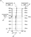
- FIG. 6 shows one example of an output image (a first distribution diagram g 1 ) of a first excavation result output by the data processing device 5 in the excavator for a trench 10 according to the present embodiment.
- the first distribution diagram g 1 is a distribution diagram showing the plurality of measurement positions and the excavation position at a certain position in the second direction D 2 when viewed along the second direction D 2 .
- the first distribution diagram g 1 is a distribution diagram showing coordinates, in the third direction D 3 , of the plurality of measurement positions and the excavation position at a certain position in the second direction D 2 .
- a position of a plurality of white round marks represents one example of the plurality of measurement positions and a position of a black rhombic mark represents one example of the excavation position.
- FIG. 7 shows one example of an output image (a second distribution diagram g 4 ) of a second excavation result output by the data processing device 5 in the excavator for a trench 10 according to the present embodiment.
- the second distribution diagram g 4 is a distribution diagram showing the plurality of measurement positions at each depth of the measurement position viewed along the vertical direction.
- the second distribution diagram g 4 is a distribution diagram showing coordinates, in the third direction D 3 , of the measurement position at each depth of the measurement position.
- a position of a plurality of white round marks represents one example of the plurality of measurement positions.
- FIG. 8 shows one example of an output image (a third distribution diagram g 5 and a fourth distribution diagram g 6 ) of a third excavation result output by the data processing device 5 in the excavator for a trench 10 according to the present embodiment.
- the third distribution diagram g 5 is a distribution diagram showing a plurality of the excavation positions viewed along the vertical direction.
- the third distribution diagram g 5 is a distribution diagram showing coordinates, in the third direction D 3 , of the plurality of excavation positions.
- a position of a plurality of black rhombic marks represents one example of the plurality of excavation positions corresponding to a plurality of positions in the second direction D 2 .
- the fourth distribution diagram g 6 is a distribution diagram showing a plurality of the trench upper end positions viewed along the vertical direction.
- the fourth distribution diagram g 6 is a distribution diagram showing coordinates, in the third direction D 3 , of the plurality of trench upper end positions.
- a position of a plurality of black triangular marks represents one example of the plurality of trench upper end positions corresponding to the plurality of positions in the second direction D 2 .
- Step S 6 the measurement position deriving portion 5 c determines whether the excavating body 14 has passed through the designated position or not. Specifically, the measurement position deriving portion 5 c determines that the excavating body 14 has passed through the designated position in a case where the excavation advancing distance exceeds a distance from the origin indicated by the designated position.
- the measurement position deriving portion 5 c causes the processing to proceed to Step S 7 and otherwise, causes the processing to proceed to Step S 8 .
- Step S 7 the interpolation processing portion 5 d derives a designated excavation position by interpolation processing based on the plurality of excavation positions and the designated position.
- the designated excavation position is a position of a part of the excavating body 14 , the part intersecting the horizontal plane at the excavation depth, when the excavating body 14 passes through the designated position.
- Step S 7 is one example of a third deriving step of deriving the designated excavation position in the present embodiment.
- the interpolation processing portion 5 d which executes the processing of Step S 7 is one example of a third deriving portion in the present embodiment.
- the interpolation processing portion 5 d selects two adjacent excavation positions which are excavation positions located adjacent to each other in the second direction D 2 with the designated position provided therebetween among the plurality of excavation positions derived in Step S 5 . Further, the interpolation processing portion 5 d derives the designated excavation position by linear interpolation processing based on the two adjacent excavation positions and the designated position.
- Step S 7 the interpolation processing portion 5 d also derives a designated trench upper end position by interpolation processing based on the trench upper end position derived in Step S 5 .
- the designated trench upper end position is a position of a part of the excavating body 14 intersecting with the ground surface when the excavating body 14 passes through the designated position.
- FIG. 9 shows one example of an output image (a fifth distribution diagram g 7 and a sixth distribution diagram g 8 ) of a fourth excavation result output by the data processing device 5 in the excavator for a trench 10 according to the present embodiment.
- the fifth distribution diagram g 7 is a distribution diagram showing a plurality of the designated excavation positions viewed along the vertical direction.
- the fifth distribution diagram g 7 is a distribution diagram showing coordinates, in the third direction D 3 , of the plurality of designated excavation positions.
- a position of a plurality of black rhombic marks represents one example of the plurality of designated excavation positions corresponding to a plurality of positions in the second direction D 2 .
- the sixth distribution diagram g 8 is a distribution diagram showing a plurality of designated trench upper end positions viewed along the vertical direction.
- the sixth distribution diagram g 8 is a distribution diagram showing coordinates, in the third direction D 3 , of the plurality of designated trench upper end positions.
- a position of a plurality of black triangular marks represents one example of the plurality of designated trench upper end positions corresponding to a plurality of the designated positions.
- Each of the coordinate values of the measurement position, the excavation position, the trench upper end portion position, the designated excavation position, and the designated trench upper end portion position derived in Steps S 4 , S 5 , and S 7 is one example of a value (information) related to a shape of the trench.
- Step S 8 the gap deriving portion 5 e derives an approximate straight line g 3 for the plurality of measurement positions derived in Step S 4 (see FIG. 6 ).
- the gap deriving portion 5 e derives the approximate straight line g 3 by the least squares method.
- the gap deriving portion 5 e derives various kinds of gap amounts.
- the gap amount includes a plurality of positional deviation amounts ⁇ x and gap angles ⁇ corresponding to the plurality of measurement positions, the excavation position, and the trench upper end portion position (see FIG. 6 ).
- the gap angle ⁇ is an angle formed with the first direction D 1 by the approximate straight line g 3 .
- the positional deviation amount ⁇ x is a difference of the measurement position or the excavation position from a target position of the measurement position or the excavation position in the third direction D 3 .
- the measurement position is derived in Step S 4 and the excavation position is derived in Step S 5 .
- the positional deviation amount ⁇ x corresponding to the excavation position is one example of information about the excavation position.
- a target position of the trench upper end portion position is a position of a reference point away from the origin in the second direction D 2 by the excavation advancing distance.
- a target position of each measurement position is a position of an intersection between a straight line along the first direction D 1 and passing through the reference point and a horizontal plane at a depth of each measurement position.
- the positional deviation amount ⁇ x corresponding to each measurement position is equal to a coordinate value of each measurement position in the third direction D 3 .
- a target position of the excavation position is a position of an intersection between the straight line along the first direction D 1 and passing through the reference point and the horizontal plane at the excavation depth.
- the positional deviation amount ⁇ x corresponding to the excavation position is equal to a coordinate value of the excavation position in the third direction D 3
- the gap deriving portion Se similarly derives positional deviation amounts ⁇ x corresponding to the designated excavation position and the designated trench upper end position in Step S 9 .
- Step S 10 the output portion 5 f records excavation data DT 2 including at least data of the plurality of measurement positions derived in Step S 4 in the storage device 64 .
- the output portion 5 f may also record the excavation data DT 2 after including, in the excavation data DT 2 , the data of the excavation position derived in Step S 5 .
- Step S 10 is one example of an output step, in the present embodiment, of outputting the information about the excavation position to the storage device 64 .
- the output portion 5 f may also record the excavation data DT 2 after including, in the excavation data DT 2 , one or both of the data of the designated excavation position derived in Step S 7 and the data of the gap derived in Step S 9 .
- Step S 11 the output portion 5 f inputs, to the display device 62 , an excavation monitoring screen including a part or all of information about positions derived in Steps S 4 , S 5 , and S 7 , information about the approximate straight line g 3 derived in Step S 9 or information about the gap amount derived in Step S 10 .
- the output portion 5 f inputs, to the display device 62 , the excavation monitoring screen including one or a plurality of a first excavation result output image Im 1 shown in FIG. 6 , a second excavation result output image Im 2 shown in FIG. 7 , a third excavation result output image Im 3 shown in FIG. 8 , and a fourth excavation result output image Im 4 shown in FIG. 9 .
- the first excavation result output image Im 1 includes the above-described first distribution diagram g 1 , numerical value data g 11 of a depth of the plurality of measurement positions corresponding to the first distribution diagram g 1 , numerical value data g 2 of the plurality of positional deviation amounts ⁇ x corresponding to the plurality of measurement positions and the excavation position, an image of the approximate straight line g 3 , and numerical value data g 31 of the gap angle ⁇ .
- the second excavation result output image Im 2 includes the second distribution diagram g 4 showing each depth of the plurality of measurement positions, the numerical value data g 11 of a depth of the plurality of measurement positions corresponding to the second distribution diagram g 4 , and numerical value data g 21 of the excavation depth.
- the third excavation result output image Im 3 includes the above-described third distribution diagram g 5 and fourth distribution diagram g 6 , and the numerical value data g 2 of the plurality of positional deviation amounts ⁇ x corresponding to a plurality of the trench upper end portion positions and the plurality of excavation positions.
- the third excavation result output image Im 3 further includes numerical value data g 22 of a representative value of the plurality of positional deviation amounts ⁇ x corresponding to the plurality of trench upper end portion positions and the plurality of excavation positions.
- the representative value is a maximum value of the positional deviation amount ⁇ x to the main body portion 11 side in the third direction D 3 , a maximum value of the positional deviation amount ⁇ x to a side oppopart to the main body portion 11 in the third direction D 3 , or an average value of the positional deviation amount ⁇ x.
- the excavation position and the trench upper end portion position are essential management parameters when excavating the trench. Accordingly, by quickly presenting, to the operator, one or both of the third distribution diagram g 5 and the fourth distribution diagram g 6 when the trench is being excavated, the operator can operate the excavator for a trench 10 more appropriately. As a result, the wall can be created with higher precision in shape.
- the fourth excavation result output image Im 4 includes the above-described fifth distribution diagram g 7 and sixth distribution diagram g 8 , numerical value data g 9 of the designated positions corresponding to the fifth distribution diagram g 7 and the sixth distribution diagram g 8 , numerical value data g 71 of the plurality of positional deviation amounts ⁇ x corresponding to the plurality of designated excavation positions, and numerical value data g 81 of the plurality of positional deviation amounts ⁇ x corresponding to a plurality of the designated trench upper end portion positions.
- the fourth excavation result output image Im 4 also includes numerical value data g 72 of a representative value of the plurality of positional deviation amounts ⁇ x corresponding to the plurality of designated excavation positions, and numerical value data g 82 of a representative value of the plurality of positional deviation amounts ⁇ x corresponding to the plurality of designated trench upper end portion positions.
- Step S 11 is one example of an output step of outputting (inputting) information about the excavation position to the display device 62 in the present embodiment.
- Step S 12 a main control portion 8 a determines whether a predetermined end condition is fulfilled or not. For example, the end condition is fulfilled in a case where predetermined end operation is conducted with respect to the operation input device 61 .
- Step S 13 the main control portion 8 a causes the processing to proceed to Step S 13 and otherwise, causes the processing to proceed to Step S 2 .
- the processing of Steps S 2 to S 11 will be executed a plurality of times corresponding to a plurality of positions of the excavating body 14 in the second direction D 2 until the end condition is fulfilled.
- Step S 13 the output portion 5 f transmits the excavation data DT 2 accumulated in the storage device 64 to the management device through the radio communication device 65 . Thereafter, the output portion 5 f causes the excavation data processing to end.
- the data processing device 5 can derive the excavation position and the designated excavation position which show a shape of the trench at the position of the depth of the excavation bottom irrespective of a position of the measuring part at which an inclination angle is detected in the excavating body 14 .
- the excavation data processing method in which while excavating a trench underground by moving, in a lateral direction, the excavating body 14 being partly buried underground, the excavator for a trench 10 forms a wall underground corresponding to the trench, is an excavation data processing method including: acquiring data output from the excavator for a trench 10 ; and deriving an information value related to a shape of the trench in order to excavate a part adjacent to one wall surface of the wall extending in the lateral direction, down to a predetermined excavation bottom positioned between an upper end portion and a lower end portion of the wall.
- the excavation data processing method has the first acquisition step, the second acquisition step, the first deriving step, the second deriving step, and the output step.
- the first acquisition step acquires reference part position data as data related to a relative position of a reference part of the excavating body 14 with respect to the origin on the ground surface, the reference part being arranged above the ground; data of a plurality of measuring part positions as data related to a relative position of each of the plurality of measuring parts in the excavating body 14 with respect to the reference part, the plurality of measuring parts being arranged underground at a space from each other in the up-down direction; and data indicative of an excavation depth as a depth from the ground surface to the excavation bottom underground.
- the second acquisition step acquires data of a plurality of inclination angles as data of an inclination angle of each of the plurality of measuring parts with respect to the vertical direction, the data being output from the excavator for a trench 10 .
- the first deriving step derives a plurality of measurement positions as relative positions of the plurality of measuring parts with respect to the origin from the reference part position data and the plurality of measuring part positions data acquired in the first acquisition step and the plurality of inclination angles data acquired in the second acquisition step.
- the second deriving step derives an excavation position (excavation bottom position) as a relative position of a part of the excavating body with respect to the origin, the part intersecting a horizontal plane below the ground surface by the excavation depth, by interpolation processing based on the plurality of measurement positions derived in the first deriving step and the excavation depth acquired in the first acquisition step.
- the output step includes a step of outputting a distribution diagram showing a part or all of the plurality of measurement positions and the excavation position viewed along the lateral direction.
- the excavation data processing method further includes a step of acquiring data indicative of a moving distance of the excavating body 14 in the lateral direction from the origin, the data being output from the excavator for a trench 10 . Then, the second acquisition step, the first deriving step, and the second deriving step are executed corresponding to a plurality of positions of the excavating body 14 in the lateral direction.
- the output step includes a step of outputting a distribution diagram of the plurality of excavation positions viewed along the vertical direction.
- the excavation data processing method further includes the third acquisition step and the third deriving step.
- the third acquisition step data indicative of one or more designated positions as positions in the lateral direction is acquired.
- the third deriving step derives a designated excavation position (designated excavation bottom position) as a position of a part of the excavating body 14 , the part intersecting a horizontal plane below the ground surface by the excavation depth when the excavating body 14 passes through the designated position by interpolation processing based on the plurality of excavation positions and the designated position.
- a designated excavation position designated excavation bottom position
- the data processing device in the present embodiment is a calculator or the like not mounted on the excavator for a trench 10 .
- the data processing device according to the present embodiment will be referred to as an external data processing device.
- the external data processing device is one example of an excavation data processing device in the present embodiment.
- the external data processing device acquires the detection data output from the excavator for a trench 10 in Step S 2 of FIG. 5 through a non-volatile storage medium or a communication network.
- the data processing device 5 of the excavator for a trench 10 records the detection data corresponding to a plurality of positions in the second direction D 2 in a portable storage device such as a USB memory, and the external data processing device acquires the detection data from the portable storage device.
- a portable storage device such as a USB memory
- Step S 13 of FIG. 5 the data processing device 5 of the excavator for a trench 10 transmits, to the management device, the detection data corresponding to a plurality of positions in the second direction D 2 , and the external data processing device acquires the detection data from the management device through a communication network.
- the external data processing device executes the processing of Steps S 1 to S 5 and Steps S 7 to S 11 shown in FIG. 5 so as to correspond to the detection data corresponding to a plurality of positions in the second direction D 2 .
- Step S 10 of FIG. 5 the external data processing device outputs, to a printer, information indicative of the excavation data DT 2 as a table of numerical value data or as the diagrams shown in FIGS. 6 to 9 .
- the information indicative of the excavation data DT 2 is output as a printed matter of the table of numerical value data or the diagrams shown in FIGS. 6 to 9 .
- Step S 10 in the present embodiment is one example of the output step in which information about the excavation position is output onto paper through the printer.
- the measurement position deriving portion 5 c and the interpolation processing portion 5 d may derive a position of one end or both ends of the cutter post 141 in a thickness direction based on the wall thickness as the measurement position, the excavation position, the trench upper end portion position, the designated excavation position, or the designated trench upper end portion position.
- the present invention provides an excavation data processing method.
- the excavation data processing method is for acquiring data output from an excavator for a trench that, while excavating a trench underground by moving, in a lateral direction, an excavating body being partly buried underground, forms a wall underground corresponding to the trench, the excavating body having a vertically long post portion extending in an up-down direction and having an endless excavating chain supported by the post portion so as to surround the post portion in the up-down direction and the lateral direction and rotating along a periphery of the post portion, and for deriving information related to a shape of the trench in order to excavate a part adjacent to one wall surface of the wall extending in the lateral direction, down to a predetermined excavation bottom positioned between an upper end portion and a lower end portion of the wall.
- the excavation data processing method includes: a first acquisition step of acquiring reference part position data as data related to a relative position of a reference part of the excavating body with respect to an origin on the ground surface, the reference part being arranged above the ground; data of a plurality of measuring part positions as data related to a relative position of each of a plurality of measuring parts in the excavating body with respect to the reference part, the plurality of measuring parts being arranged underground at a space from each other in the up-down direction; and data indicative of an excavation depth as a depth from the ground surface to the excavation bottom underground; a second acquisition step of acquiring data of a plurality of inclination angles as data of an inclination angle of each of the plurality of measuring parts with respect to a vertical direction, the data being output from the excavator for a trench; a first deriving step of deriving a plurality of measurement positions as relative positions of the plurality of measuring parts with respect to the origin from the reference part position data and the plurality of measuring part positions data acquired in the
- an excavation bottom position indicative of a shape of a trench at a position of a depth of the excavation bottom in the trench can be derived and output irrespective of a position of a measuring part of an excavating body where an inclination angle is detected. Therefore, when a building is constructed adjacent to a wall formed by the excavator for a trench, the position of the excavation bottom where a foundation part of the building is formed can be precisely grasped based on the information output in the output step.
- the output step preferably includes a step of outputting a distribution diagram showing a part or all of the plurality of measurement positions and the excavation bottom position viewed along the lateral direction.
- a relative positional relationship between a plurality of measurement positions and an excavation bottom position viewed from the lateral direction can be visually grasped from the distribution diagram output in the output step. It is therefore possible to grasp shapes of an excavation bottom and a trench (wall) on the periphery thereof with ease.
- the above method preferably further includes a step of acquiring data indicative of a moving distance of the excavating body in the lateral direction from the origin, the data being output from the excavator for a trench, in which the second acquisition step, the first deriving step, and the second deriving step are executed corresponding to a plurality of positions of the excavating body in the lateral direction.
- the output step preferably includes a step of outputting a distribution diagram of a plurality of the excavation bottom positions viewed along the vertical direction.
- the above method preferably further includes: a third acquisition step of acquiring data indicative of one or more designated positions as positions in the lateral direction; and a third deriving step of deriving a designated excavation bottom position as a position of a part of the excavating body, the part intersecting a horizontal plane below the ground surface by the excavation depth when the excavating body passes through the designated position by interpolation processing based on the plurality of excavation bottom positions and the designated position.
- the present invention also provides an excavation data processing device.
- the excavation data processing device acquires data output from an excavator for a trench that, while excavating a trench underground by moving, in a lateral direction, an excavating body being partly buried underground, forms a wall underground corresponding to the trench, the excavating body having a vertically long post portion extending in an up-down direction and having an endless excavating chain supported by the post portion so as to surround the post portion in the up-down direction and the lateral direction and rotating along a periphery of the post portion, and derives information related to a shape of the trench in order to excavate a part adjacent to one wall surface of the wall extending in the lateral direction, down to a predetermined excavation bottom positioned between an upper end portion and a lower end portion of the wall.
- the excavation data processing device includes: a first acquisition portion which acquires reference part position data as data related to a relative position of a reference part of the excavating body with respect to an origin on the ground surface, the reference part being arranged above the ground; data of a plurality of measuring part positions as data related to a relative position of each of a plurality of measuring parts in the excavating body with respect to the reference part, the plurality of measuring parts being arranged underground at a space from each other in the up-down direction; and data indicative of an excavation depth as a depth from the ground surface to the excavation bottom underground; a second acquisition portion which acquires data of a plurality of inclination angles as data of an inclination angle of each of the plurality of measuring parts with respect to a vertical direction, the data being output from the excavator for a trench; a first deriving portion which derives a plurality of measurement positions as relative positions of the plurality of measuring parts with respect to the origin from the reference part position data and the plurality of measuring part positions data acquired by the first
- an excavation bottom position indicative of a shape of a trench at a position of a depth of the excavation bottom in the trench can be derived and output irrespective of a position of a measuring part in the excavating body where an inclination angle is detected. Therefore, when a building is constructed adjacent to a wall formed by the excavator for a trench, the position of the excavation bottom where a foundation part of the building is formed can be precisely grasped based on the information output in the output step.
- the present invention further provides an excavator for a trench.
- the excavator for a trench includes: an excavating body having a vertically long post portion extending in an up-down direction and having an endless excavating chain supported by the post portion so as to surround the post portion in the up-down direction and a lateral direction and rotating along a periphery of the post portion; an inclination angle detection device which detects and outputs an inclination angle, formed with respect to the vertical direction, of each of a plurality of measuring parts arranged at a space from each other in the up-down direction in the excavating body; and the above-described excavation data processing device.
- the excavating body While moving in the lateral direction to excavate a trench underground, the excavating body being partly buried underground forms a wall underground corresponding to the trench, and the excavation data processing device acquires data of the plurality of inclination angle detection values from the inclination angle detection device to derive information related to a shape of the trench.
- the position of the excavation bottom where a foundation part of the building is formed can be precisely grasped.
Landscapes
- Engineering & Computer Science (AREA)
- Mining & Mineral Resources (AREA)
- Civil Engineering (AREA)
- General Engineering & Computer Science (AREA)
- Structural Engineering (AREA)
- Mechanical Engineering (AREA)
- Physics & Mathematics (AREA)
- General Physics & Mathematics (AREA)
- Radar, Positioning & Navigation (AREA)
- Remote Sensing (AREA)
- Bulkheads Adapted To Foundation Construction (AREA)
Abstract
Description
[Formula 1]
Ya=−La·sin(ϕa)
Za=+La·cos(ϕa) (1)
[Formula 2]
Yb=Lb·sin(ϕb)−La·sin(ϕa)
Zb=−Lb·cos(ϕb)+La·cos(ϕa) (2)
Claims (1)
Applications Claiming Priority (2)
| Application Number | Priority Date | Filing Date | Title |
|---|---|---|---|
| JP2019126590 | 2019-07-08 | ||
| JP2019-126590 | 2019-07-08 |
Publications (2)
| Publication Number | Publication Date |
|---|---|
| US20210010231A1 US20210010231A1 (en) | 2021-01-14 |
| US12110654B2 true US12110654B2 (en) | 2024-10-08 |
Family
ID=74102212
Family Applications (1)
| Application Number | Title | Priority Date | Filing Date |
|---|---|---|---|
| US16/920,851 Active 2043-06-16 US12110654B2 (en) | 2019-07-08 | 2020-07-06 | Excavation data processing method, excavation data processing device, and excavator for trench |
Country Status (2)
| Country | Link |
|---|---|
| US (1) | US12110654B2 (en) |
| JP (1) | JP7036132B2 (en) |
Families Citing this family (1)
| Publication number | Priority date | Publication date | Assignee | Title |
|---|---|---|---|---|
| CN115201832B (en) * | 2022-05-25 | 2023-11-24 | 福建省昊立建设工程有限公司 | Monitoring system and monitoring method for amphibious excavator |
Citations (4)
| Publication number | Priority date | Publication date | Assignee | Title |
|---|---|---|---|---|
| US20010049891A1 (en) * | 2000-06-09 | 2001-12-13 | Kobelco Construction Machinery Co., Ltd. | Excavator for a ditch and excavating method therefor |
| US20040148818A1 (en) * | 2002-08-30 | 2004-08-05 | Kobelco Construction Machinerty Co., Ltd | Continuous underground trench excavating method and excavator therefor |
| US20200032483A1 (en) * | 2018-07-26 | 2020-01-30 | Built Robotics Inc. | Excavating earth from a dig site using an excavation vehicle |
| US20200329631A1 (en) * | 2019-04-18 | 2020-10-22 | Cnh Industrial America Llc | System and method for controlling the operation of a seed-planting implement based on the operation of its furrow-closing assembly |
Family Cites Families (4)
| Publication number | Priority date | Publication date | Assignee | Title |
|---|---|---|---|---|
| JP3821924B2 (en) * | 1997-09-16 | 2006-09-13 | 大成建設株式会社 | Ditch drilling equipment |
| JP4146579B2 (en) * | 1999-06-18 | 2008-09-10 | 西松建設株式会社 | Control method of groove excavator |
| JP3835341B2 (en) * | 2002-05-10 | 2006-10-18 | コベルコクレーン株式会社 | Ditch excavator and ditch excavation support method |
| NL2008177C2 (en) * | 2012-01-25 | 2013-07-29 | Sterk Cellar Murum B V | DEVICE FOR DIGGING A SLOT. |
-
2020
- 2020-01-17 JP JP2020006251A patent/JP7036132B2/en active Active
- 2020-07-06 US US16/920,851 patent/US12110654B2/en active Active
Patent Citations (5)
| Publication number | Priority date | Publication date | Assignee | Title |
|---|---|---|---|---|
| US20010049891A1 (en) * | 2000-06-09 | 2001-12-13 | Kobelco Construction Machinery Co., Ltd. | Excavator for a ditch and excavating method therefor |
| JP2001348906A (en) | 2000-06-09 | 2001-12-21 | Kobelco Contstruction Machinery Ltd | Trench excavator, method of displaying trench wall shape in trench excavator and method of correcting trench wall shape |
| US20040148818A1 (en) * | 2002-08-30 | 2004-08-05 | Kobelco Construction Machinerty Co., Ltd | Continuous underground trench excavating method and excavator therefor |
| US20200032483A1 (en) * | 2018-07-26 | 2020-01-30 | Built Robotics Inc. | Excavating earth from a dig site using an excavation vehicle |
| US20200329631A1 (en) * | 2019-04-18 | 2020-10-22 | Cnh Industrial America Llc | System and method for controlling the operation of a seed-planting implement based on the operation of its furrow-closing assembly |
Also Published As
| Publication number | Publication date |
|---|---|
| JP2021011810A (en) | 2021-02-04 |
| US20210010231A1 (en) | 2021-01-14 |
| JP7036132B2 (en) | 2022-03-15 |
Similar Documents
| Publication | Publication Date | Title |
|---|---|---|
| US10190288B2 (en) | Excavation measurement with light curtain | |
| JP7133562B2 (en) | Augmented reality display for material moving machines | |
| KR102570490B1 (en) | Shovel and shovel display device | |
| CN109757114B (en) | Display control device for working machine, and display control method for working machine | |
| CN104141483B (en) | Digital drilling control method and system for surface deep hole blasting | |
| EP3119660B1 (en) | System and method for positioning construction machine | |
| JP5312890B2 (en) | Excavation management method for invert section | |
| CN1117317A (en) | Method and apparatus for operating geography-altering machinery relative to a work site | |
| JP6918716B2 (en) | Construction machinery | |
| CN106065767A (en) | For producing the drilling equipment of cased bore-bole and for the method operating drilling equipment | |
| JP6529058B1 (en) | Construction machine management system, construction machine management program, construction machine management method, construction machine and external management device for construction machine | |
| US20080230270A1 (en) | Arrangement for Positioning Rock Drilling Rig on Drilling Site | |
| US20240125180A1 (en) | Mobility Control for Mobile Drilling Rig | |
| US12110654B2 (en) | Excavation data processing method, excavation data processing device, and excavator for trench | |
| US11761167B2 (en) | Automatic depth control system | |
| KR101629716B1 (en) | Coordinate Measuring System for Excavating Work and Method Thereof | |
| JP6496540B2 (en) | Method for estimating borehole shape | |
| JP3177691U (en) | Pile driver or pile driver capable of accurate pile driving using light | |
| JP7195663B1 (en) | Construction machine display method, construction machine display control system, and construction machine display control program | |
| JP6894326B2 (en) | Caisson aperture ratio calculation system, aperture ratio calculation method and aperture ratio calculation program | |
| JP3659826B2 (en) | Work management system for trencher type soil cement wall excavator | |
| WO2017061512A1 (en) | Work-performing method, control system for work machine, and work machine | |
| EP4253669B1 (en) | Measuring system for a building and working machine | |
| TR2023004191A2 (en) | Operator excavation ranking system. | |
| JP6901796B2 (en) | Plane position detection structure of soil cement column and soil cement column position coordinate recording system using this |
Legal Events
| Date | Code | Title | Description |
|---|---|---|---|
| AS | Assignment |
Owner name: KOBELCO CONSTRUCTION MACHINERY CO., LTD., JAPAN Free format text: ASSIGNMENT OF ASSIGNORS INTEREST;ASSIGNOR:KUSAKABE, KEISUKE;REEL/FRAME:053122/0540 Effective date: 20200421 |
|
| FEPP | Fee payment procedure |
Free format text: ENTITY STATUS SET TO UNDISCOUNTED (ORIGINAL EVENT CODE: BIG.); ENTITY STATUS OF PATENT OWNER: LARGE ENTITY |
|
| STPP | Information on status: patent application and granting procedure in general |
Free format text: DOCKETED NEW CASE - READY FOR EXAMINATION |
|
| STPP | Information on status: patent application and granting procedure in general |
Free format text: NON FINAL ACTION MAILED |
|
| STPP | Information on status: patent application and granting procedure in general |
Free format text: RESPONSE TO NON-FINAL OFFICE ACTION ENTERED AND FORWARDED TO EXAMINER |
|
| STPP | Information on status: patent application and granting procedure in general |
Free format text: FINAL REJECTION MAILED |
|
| STPP | Information on status: patent application and granting procedure in general |
Free format text: DOCKETED NEW CASE - READY FOR EXAMINATION |
|
| STPP | Information on status: patent application and granting procedure in general |
Free format text: NOTICE OF ALLOWANCE MAILED -- APPLICATION RECEIVED IN OFFICE OF PUBLICATIONS |
|
| ZAAB | Notice of allowance mailed |
Free format text: ORIGINAL CODE: MN/=. |
|
| STPP | Information on status: patent application and granting procedure in general |
Free format text: PUBLICATIONS -- ISSUE FEE PAYMENT VERIFIED |
|
| STCF | Information on status: patent grant |
Free format text: PATENTED CASE |