US12108564B2 - Flow path module, coolant distribution device, and server - Google Patents
Flow path module, coolant distribution device, and server Download PDFInfo
- Publication number
- US12108564B2 US12108564B2 US17/728,940 US202217728940A US12108564B2 US 12108564 B2 US12108564 B2 US 12108564B2 US 202217728940 A US202217728940 A US 202217728940A US 12108564 B2 US12108564 B2 US 12108564B2
- Authority
- US
- United States
- Prior art keywords
- flow resistance
- pipeline
- connecting end
- heat exchange
- coolant
- Prior art date
- Legal status (The legal status is an assumption and is not a legal conclusion. Google has not performed a legal analysis and makes no representation as to the accuracy of the status listed.)
- Active, expires
Links
Images


Classifications
-
- G—PHYSICS
- G06—COMPUTING OR CALCULATING; COUNTING
- G06F—ELECTRIC DIGITAL DATA PROCESSING
- G06F1/00—Details not covered by groups G06F3/00 - G06F13/00 and G06F21/00
- G06F1/16—Constructional details or arrangements
- G06F1/20—Cooling means
- G06F1/206—Cooling means comprising thermal management
-
- H—ELECTRICITY
- H05—ELECTRIC TECHNIQUES NOT OTHERWISE PROVIDED FOR
- H05K—PRINTED CIRCUITS; CASINGS OR CONSTRUCTIONAL DETAILS OF ELECTRIC APPARATUS; MANUFACTURE OF ASSEMBLAGES OF ELECTRICAL COMPONENTS
- H05K7/00—Constructional details common to different types of electric apparatus
- H05K7/20—Modifications to facilitate cooling, ventilating, or heating
- H05K7/20218—Modifications to facilitate cooling, ventilating, or heating using a liquid coolant without phase change in electronic enclosures
- H05K7/20272—Accessories for moving fluid, for expanding fluid, for connecting fluid conduits, for distributing fluid, for removing gas or for preventing leakage, e.g. pumps, tanks or manifolds
-
- H—ELECTRICITY
- H05—ELECTRIC TECHNIQUES NOT OTHERWISE PROVIDED FOR
- H05K—PRINTED CIRCUITS; CASINGS OR CONSTRUCTIONAL DETAILS OF ELECTRIC APPARATUS; MANUFACTURE OF ASSEMBLAGES OF ELECTRICAL COMPONENTS
- H05K7/00—Constructional details common to different types of electric apparatus
- H05K7/20—Modifications to facilitate cooling, ventilating, or heating
- H05K7/20218—Modifications to facilitate cooling, ventilating, or heating using a liquid coolant without phase change in electronic enclosures
- H05K7/20263—Heat dissipaters releasing heat from coolant
-
- H—ELECTRICITY
- H05—ELECTRIC TECHNIQUES NOT OTHERWISE PROVIDED FOR
- H05K—PRINTED CIRCUITS; CASINGS OR CONSTRUCTIONAL DETAILS OF ELECTRIC APPARATUS; MANUFACTURE OF ASSEMBLAGES OF ELECTRICAL COMPONENTS
- H05K7/00—Constructional details common to different types of electric apparatus
- H05K7/20—Modifications to facilitate cooling, ventilating, or heating
- H05K7/20709—Modifications to facilitate cooling, ventilating, or heating for server racks or cabinets; for data centers, e.g. 19-inch computer racks
- H05K7/20763—Liquid cooling without phase change
- H05K7/20781—Liquid cooling without phase change within cabinets for removing heat from server blades
-
- Y—GENERAL TAGGING OF NEW TECHNOLOGICAL DEVELOPMENTS; GENERAL TAGGING OF CROSS-SECTIONAL TECHNOLOGIES SPANNING OVER SEVERAL SECTIONS OF THE IPC; TECHNICAL SUBJECTS COVERED BY FORMER USPC CROSS-REFERENCE ART COLLECTIONS [XRACs] AND DIGESTS
- Y02—TECHNOLOGIES OR APPLICATIONS FOR MITIGATION OR ADAPTATION AGAINST CLIMATE CHANGE
- Y02D—CLIMATE CHANGE MITIGATION TECHNOLOGIES IN INFORMATION AND COMMUNICATION TECHNOLOGIES [ICT], I.E. INFORMATION AND COMMUNICATION TECHNOLOGIES AIMING AT THE REDUCTION OF THEIR OWN ENERGY USE
- Y02D10/00—Energy efficient computing, e.g. low power processors, power management or thermal management
Definitions
- the disclosure relates to a fluid flow path module, a fluid distribution device, and an electronic equipment, and more particularly to a flow path module with adjustable flow resistance, a coolant distribution device, and a server.
- the heat dissipation requirements increase accordingly.
- the heat generated by a heating element of the server is transferred to a water-cooling plate, and the water-cooling plate is connected to a coolant distribution device (that is, a coolant distribution unit, CDU) through a coolant pipeline, so that a coolant may be circulated between the water-cooling plate and the coolant distribution device to continuously dissipate heat from the water-cooling plate.
- a coolant distribution device that is, a coolant distribution unit, CDU
- the water-cooling plate has a closed pipeline structure, and the internal state cannot be known by naked eye observation or general measurement. Usually, the internal state can be known only by testing the flow resistance and the cooling capacity or by taking X-ray photographs of the internal structure, so as to examine the quality of the water-cooling plate.
- the prior art In order to detect the water-cooling plate without shutting down the server, the prior art generally uses a detection circuit to detect whether the water-cooling plate leaks. However, such method consumes extra power, the detection circuit needs to be matched with the design of a mainboard of the server, and whether the water-cooling plate is blocked cannot be detected.
- the disclosure provides a flow path module with adjustable flow resistance, a coolant distribution device, and a server, which can detect a state of a corresponding heat exchange element by monitoring the flow path module.
- a flow path module with adjustable flow resistance of the disclosure is adapted to a heat exchange element and a coolant and includes a pipeline structure and at least one flow resistance element.
- the pipeline structure is adapted to be connected to the heat exchange element.
- the flow resistance element is disposed in the pipeline structure, and the coolant flows through the heat exchange element from the pipeline structure.
- a flow resistance of the flow resistance element is adapted to be adjusted corresponding to a flow resistance of the heat exchange element.
- the pipeline structure includes a master pipeline line set and a branch pipeline set
- the at least one flow resistance element includes a first flow resistance element and a valve body
- the valve body is movably disposed in the branch pipeline set
- the master pipeline set is adapted to be connected to the heat exchange element
- the coolant is adapted to flow through the heat exchange element through the master pipeline set
- the branch pipeline set is communicated with the master pipeline set and has a monitor section
- the first flow resistance element is disposed in the branch pipeline set
- a flow resistance of the first flow resistance element is adjusted, so that a flux of the coolant in the monitor section is a predetermined value, and when the flow resistance of the heat exchange element changes, the flux of the coolant in the monitor section deviates from the predetermined value.
- the predetermined value is zero.
- the master pipeline set includes a first master pipeline and a second master pipeline, the first master pipeline has a first inlet end and a first outlet end, the second master pipeline has a second inlet end and a second outlet end, the first outlet end and the second inlet end are adapted to be connected to a heat exchange element, and the first inlet end and the second outlet end are adapted to be connected to another heat exchange element.
- the heat exchange element is a heat exchange element in a server
- the another heat exchange element is a heat exchange element in a coolant distribution device.
- the branch pipeline set includes a first branch pipeline and a second branch pipeline
- the first branch pipeline has a first connecting end and a second connecting end
- the first connecting end is connected to the first master pipeline and is located between the first inlet end and the first outlet end
- the second connecting end is connected to the second master pipeline and is located between the second inlet end and the second outlet end
- the second branch pipeline has a third connecting end and a fourth connecting end
- the third connecting end is connected to the first master pipeline and is located between the first inlet end and the first connecting end
- the fourth connecting end is connected to the first branch pipeline and is located between the first connecting end and the second connecting end
- the first flow resistance element is disposed in the first branch pipeline and is located between the fourth connecting end and the second connecting end
- the monitor section is located between the first connecting end and the fourth connecting end.
- the at least flow resistance element further includes a second flow resistance element and a third flow resistance element
- the second flow resistance element is disposed in the first master pipeline and is located between the first connecting end and the third connecting end
- the third flow resistance element is disposed in the second branch pipeline
- the flow resistance of the first flow resistance element is adapted to be adjusted according to the flux of the coolant, a flow resistance of the second flow resistance element, and a flow resistance of the third flow resistance element, so that the flux of the coolant between the first connecting end and the fourth connecting end is the predetermined value.
- the flow path module further includes a monitor element.
- the monitor element is disposed in the monitor section, and the monitor element is adapted to monitor whether the flux of the coolant in the monitor section is the predetermined value.
- the monitor element includes a turbine, a flow meter, or a flux meter.
- the monitor section includes a transparent pipeline.
- a coolant distribution device of the disclosure is adapted to a heat exchange element and a coolant and includes a device body and a flow path module with adjustable flow resistance.
- the flow path module with adjustable flow resistance includes a pipeline structure and at least one flow resistance element.
- the pipeline structure is adapted to be connected between the heat exchange element and the device body.
- the flow resistance element is disposed in the pipeline structure. The coolant flows through the heat exchange element from the pipeline structure, and a flow resistance of the flow resistance element is adapted to be adjusted corresponding to a flow resistance of the heat exchange element.
- the pipeline structure includes a master pipeline line set and a branch pipeline set
- the at least one flow resistance element includes a first flow resistance element and a valve body
- the valve body is movably disposed in the branch pipeline set
- the master pipeline set is adapted to be connected to the heat exchange element
- the coolant is adapted to flow through the heat exchange element through the master pipeline set
- the branch pipeline set is communicated with the master pipeline set and has a monitor section
- the first flow resistance element is disposed in the branch pipeline set
- a flow resistance of the first flow resistance element is adjusted, so that a flux of the coolant in the monitor section is a predetermined value, and when the flow resistance of the heat exchange element changes, the flux of the coolant in the monitor section deviates from the predetermined value.
- the predetermined value is zero.
- the master pipeline set includes a first master pipeline and a second master pipeline
- the first master pipeline has a first inlet end and a first outlet end
- the second master pipeline has a second inlet end and a second outlet end
- the first outlet end and the second inlet end are adapted to be connected to the heat exchange element
- the coolant distribution device includes another heat exchange element
- the another heat exchange element is disposed in the device body
- the first inlet end and the second outlet end are adapted to be connected to the another heat exchange element.
- the branch pipeline set includes a first branch pipeline and a second branch pipeline
- the first branch pipeline has a first connecting end and a second connecting end
- the first connecting end is connected to the first master pipeline and is located between the first inlet end and the first outlet end
- the second connecting end is connected to the second master pipeline and is located between the second inlet end and the second outlet end
- the second branch pipeline has a third connecting end and a fourth connecting end
- the third connecting end is connected to the first master pipeline and is located between the first inlet end and the first connecting end
- the fourth connecting end is connected to the first branch pipeline and is located between the first connecting end and the second connecting end
- the first flow resistance element is disposed in the first branch pipeline and is located between the fourth connecting end and the second connecting end
- the monitor section is located between the first connecting end and the fourth connecting end.
- the at least flow resistance element further includes a second flow resistance element and a third flow resistance element
- the second flow resistance element is disposed in the first master pipeline and is located between the first connecting end and the third connecting end
- the third flow resistance element is disposed in the second branch pipeline
- the flow resistance of the first flow resistance element is adapted to be adjusted according to the flux of the coolant, a flow resistance of the second flow resistance element, and a flow resistance of the third flow resistance element, so that the flux of the coolant between the first connecting end and the fourth connecting end is the predetermined value.
- the heat exchange element is a heat exchange element in a server.
- the flow path module with adjustable flow resistance further includes a monitor element, the monitor element is disposed in the monitor section, and the monitor element is adapted to monitor whether the flux of the coolant in the monitor section is the predetermined value.
- the monitor element includes a turbine, a flow meter, or a flux meter.
- the monitor section includes a transparent pipeline.
- a server of the disclosure is adapted to a coolant and includes a server body, a heat exchange element, and a flow path module with adjustable flow resistance.
- the heat exchange element is disposed in the server body.
- the flow path module with adjustable flow resistance includes a pipeline structure and at least one flow resistance element.
- the pipeline structure is connected to the heat exchange element.
- the flow resistance element is disposed in the pipeline structure.
- the coolant flows through the heat exchange element from the pipeline structure, and a flow resistance of the flow resistance element is adapted to be adjusted corresponding to a flow resistance of the heat exchange element.
- FIG. 1 is a schematic diagram of a flow path module connected between a coolant distribution device and a server according to an embodiment of the disclosure.
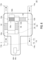
- FIG. 2 is a schematic diagram of the flow path module of FIG. 1 .
- FIG. 3 A to FIG. 3 C are flow resistance curves of the flow path module of FIG. 2 .
- FIG. 4 is a schematic diagram of a flow path module according to another embodiment of the disclosure.
- FIG. 5 is a schematic diagram of a server according to another embodiment of the disclosure.
- FIG. 6 is a schematic diagram of a coolant distribution device according to another embodiment of the disclosure.
- FIG. 1 is a schematic diagram of a flow path module connected between a coolant distribution device and a server according to an embodiment of the disclosure.
- FIG. 2 is a schematic diagram of the flow path module of FIG. 1 .
- the pipeline structure of a flow channel module 100 of the embodiment includes a master pipeline set 110 .
- the master pipeline set 110 is connected between a heat exchange element 52 (for example, a water-cooling plate) of a server 50 and a heat exchange element 62 of a coolant distribution device (that is, a coolant distribution unit, CDU) 60 .
- the heat generated by the heating element of the server 50 is transferred to the heat exchange element 52 .
- a coolant C is adapted to flow through the heat exchange element 52 of the server 50 and the heat exchange element 62 of the coolant distribution device 60 through the master pipeline set 110 and is continuously circulated.
- the high temperature coolant C is cooled down at the heat exchange element 62 to continuously dissipate heat from the heat exchange element 52 of the server 50 .
- the coolant distribution device 60 controls the heat exchange element 62 to exchange heat and controls a pump 66 to drive the coolant C to flow by, for example, a controller 64 thereof.
- the specific functions of the coolant distribution device 60 are known in the prior art, so details are not repeated here.
- the pipeline structure of the flow path module 100 of the embodiment further includes a branch pipeline set 120
- the liquid flow path module 100 further includes a first flow resistance element 130 .
- the first flow resistance element 130 is disposed in the branch pipeline set 120 , and the flow resistance of the first flow resistance element 130 is adapted to be adjusted corresponding to the flow resistance of the heat exchange element 52 .
- the branch pipeline set 120 is communicated with the master pipeline set 110 and has a monitor section 120 a .
- the flow resistance of the first flow resistance element 130 in the branch pipeline set 120 may be adjusted, so that the flux of the coolant C in the monitor section 120 a of the branch pipeline set 120 is a predetermined value (for example, zero).
- the flux of the coolant C in the monitor section 120 a of the branch pipeline set 120 correspondingly deviates from the predetermined value (for example, zero), so that a user may know that the state of the heat exchange element 52 is abnormal accordingly.
- the state of the corresponding heat exchange element 52 may be detected by monitoring the flow path module 100 without the need for a detection circuit that consumes extra power to detect the state of the heat exchange element 52 , and the design of a mainboard of the server 50 does not need to be matched with the detection circuit.
- the master pipeline set 110 of the embodiment includes a first master pipeline 112 and a second master pipeline 114 , the first master pipeline 112 has a first inlet end 112 a and a first outlet end 112 b , and the second master pipeline 114 has a second inlet end 114 a and a second outlet end 114 b .
- the first outlet end 112 b of the first master pipeline 112 and the second inlet end 114 a of the second master pipeline 114 are connected to the heat exchange element 52 of the server 50
- the first inlet end 112 a of the first master pipeline 112 is connected to the heat exchange element 62 of the coolant distribution device 60 through elements such as the pump 66 of the coolant distribution device 60
- the second outlet end 114 b of the second master pipeline 114 is connected to the heat exchange element 62 of the coolant distribution device 60 .
- the coolant C enters the first master pipeline 112 from the coolant distribution device 60 through the first inlet end 112 a , and reaches the heat exchange element 52 of the server 50 through the first outlet end 112 b .
- the coolant C After absorbing the heat of the heat exchange element 52 , the coolant C enters the second master pipeline 114 through the second inlet end 114 a , and reaches the coolant distribution device 60 through the second outlet end 114 b .
- the coolant C is continuously circulated between the server 50 and the coolant distribution device 60 in this way.
- the branch pipeline set 120 of the embodiment includes a first branch pipeline 122 and a second branch pipeline 124 .
- the first branch pipeline 122 has a first connecting end 122 a and a second connecting end 122 b , the first connecting end 122 a is connected to the first master pipeline 112 and is located between the first inlet end 112 a and the first outlet end 112 b , and the second connecting end 122 b is connected to the second master pipeline 114 and is located between the second inlet end 114 a and the second outlet end 114 b .
- the second branch pipeline 124 has a third connecting end 124 a and a fourth connecting end 124 b , the third connecting end 124 a is connected to the first master pipeline 112 and is located between the first inlet end 112 a and the first connecting end 122 a , and the fourth connecting end 124 b is connected to the first branch pipeline 122 and is located between the first connecting end 122 a and the second connecting end 122 b .
- the first flow resistance element 130 is disposed in the first branch pipeline 122 and is located between the fourth connecting end 124 b and the second connecting end 122 b , and the monitor section 120 a is located between the first connecting end 122 a and the fourth connecting end 124 b .
- the flow path module 100 of the embodiment further includes a second flow resistance element 140 and a third flow resistance element 150 , which are, for example, fin sets.
- the second flow resistance element 140 is disposed in the first master pipeline 112 and is located between the first connecting end 122 a and the third connecting end 124 a
- the third flow resistance element 150 is disposed in the second branch pipeline 124 .
- the flow resistance of the first flow resistance element 130 is adapted to be adjusted according to the flux of the coolant C, the flow resistance of the second flow resistance element 140 , and the flow resistance of the third flow resistance element 150 , so that the flux of the coolant C between the first connecting end 122 a and the fourth connecting end 124 b is the predetermined value (for example, zero), which will be described in detail below.
- a flow resistance Z 1 that is, the flow resistance of the first flow resistance element 130
- a flux Q 1 that is, and a pressure difference ⁇ P 1 between the second connecting end 122 b and the fourth connecting end 124 b shown in FIG. 2
- a flow resistance Z 2 that is, the flow resistance of the second flow resistance element 140
- a flux Q 2 that is, and a pressure difference ⁇ P 2 between the third connecting end 124 a and the first connecting end 122 a
- a flow resistance Z 3 that is, the flow resistance of the third flow resistance element 150
- a flux Q 3 that is, and a pressure difference ⁇ P 3 between the third connecting end 124 a and the fourth connecting end 124 b .
- the flow resistance Zx varies with the flow resistance of the heat exchange element 52 of the server 50 .
- Equations (3) to (7) may be obtained from the flow direction of the coolant C in FIG. 2 .
- a flux Qt is the total flux of the coolant C when entering the flow path module 100 or leaving the flow path module 100 .
- Qt Q 2+ Q 3 (3)
- Qx Q 2+ Qg (4)
- Q 3 Q 1+ Qg (5)
- ⁇ P 2 ⁇ P 3+ ⁇ Pg (6)
- ⁇ P 1 ⁇ Px+ ⁇ Pg (7)
- Equation (1) when the flux Qg is zero (that is, the flux of the coolant C between the first connecting end 122 a and the fourth connecting end 124 b is zero), the pressure difference ⁇ Pg is also zero, and bringing the condition into Equations (4) to (7), the following Equations (8) to (11) may be obtained.
- Qx Q 2 (8)
- Q 3 Q 1 (9)
- ⁇ P 2 ⁇ P 3 (10)
- ⁇ P 1 ⁇ Px (11)
- the flux Qt provided by the coolant distribution device 60 is known, and the flow resistance Z 2 and the flow resistance Z 3 are fixed, so the flux Q 2 and the flux Q 3 are known.
- a flow resistance value of the first flow resistance element 130 satisfying Equations (4) to (7) must be obtained, so that the flux Qg is zero.
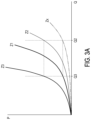
- FIG. 3 A to FIG. 3 C are flow resistance curves of the flow path module of FIG. 2 . As shown in FIG. 3 A , if the flow resistance Z 2 , the flow resistance Z 3 , and the flow resistance Zx are known, the flow resistance Z 1 may be found to satisfy Equations (4) to (7).
- FIG. 3 B and FIG. 3 A are that the flow resistance Zx of FIG. 3 B is closer to the vertical axis, the flow resistance Z 2 is correspondingly closer to the vertical axis, the physical meaning may be that the number of fins in the heat exchange element 52 (the water-cooling plate) is greater and the density of the fins is greater, an inner diameter of the pipeline in the heat exchange element 52 (the water-cooling plate) is smaller and the pipeline has more bending, and/or the number of water-cooling plates in series is greater, so that the values of a and b in Equation (1) are greater.
- FIG. 3 C and FIG. 3 B are that the flow resistance Zx of FIG.
- the physical meaning may be that the number of fins in the heat exchange element 52 (the water-cooling plate) is greater and the density of the fins is greater, an inner diameter of the pipeline in the heat exchange element 52 (the water-cooling plate) is smaller and the pipeline has more bending, and/or the number of water-cooling plates in series is greater, so that the values of a and b in Equation (1) are greater.
- the first flow resistance element 130 may include a valve body 132 .
- the valve body 132 is movably disposed in the branch pipeline set 120 , and the user may drive the valve body 132 to move through a knob 134 and a corresponding screw set 136 to adjust the flow resistance of the first flow resistance element 130 .
- the first flow resistance element 130 may be an adjustable flow resistance element in other forms, which is not limited in the disclosure.
- the flow path module 100 of the embodiment further includes a monitor element 160 .
- the monitor element 160 is disposed in the monitor section 120 a and is adapted to monitor whether the flux of the coolant C in the monitor section 120 a is the predetermined value (for example, zero).
- the monitor element 160 is a turbine shown in FIG. 1 . When the flux in the monitor section 120 a is not zero, the turbine rotates accordingly.
- the monitor section 120 a includes a transparent pipeline, and the user may observe whether the turbine rotates through the transparent pipeline, so as to judge whether the flux in the monitor section 120 a is zero.
- the heat exchange element 52 (the water-cooling plate) is judged as leaking and the flow resistance thereof is reduced.
- the heat exchange element 52 (the water-cooling plate) is judged as being blocked and the flow resistance thereof is increased.
- the user may replace the heat exchange element 52 (the water-cooling plate) accordingly.
- FIG. 4 is a schematic diagram of a flow path module according to another embodiment of the disclosure.
- a monitor element 160 A of the embodiment shown in FIG. 4 is a flow meter or a flux meter, which is connected to a plug-in monitoring system 162 .
- the monitor element 160 A measures that the coolant C flows from the fourth connecting end 124 b toward the first connecting end 122 a in the monitor section 120 a , the heat exchange element 52 (the water-cooling plate) is judged as leaking and the flow resistance thereof is reduced, and a corresponding signal is issued to the monitoring system 162 to let the user know that the heat exchange element 52 (the water-cooling plate) needs to be replaced.
- the monitor element 160 A measures that the coolant C flows from the first connecting end 122 a toward the fourth connecting end 124 b in the monitor section 120 a , the heat exchange element 52 (the water-cooling plate) is judged as being blocked and the flow resistance is increased, and a corresponding signal is issued to the monitoring system 162 to let the user know that the heat exchange element 52 (the water-cooling plate) needs to be replaced.
- FIG. 5 is a schematic diagram of a server according to another embodiment of the disclosure.
- the difference between the embodiment shown in FIG. 5 and the embodiment shown in FIG. 4 is that the flow path module 100 of the embodiment shown in FIG. 5 is integrated with a server body 50 a to form a server 50 A including the flow path module 100 .
- the connection and interaction manners between the flow path module 100 and the server body 50 a and the coolant distribution device are the same or similar to the connection and interaction manners between the flow path module 100 and the server 50 and the coolant distribution device 60 shown in FIG. 1 , FIG. 2 , and/or FIG. 4 , which will not be repeated here.
- FIG. 6 is a schematic diagram of a coolant distribution device according to another embodiment of the disclosure.
- the difference between the embodiment shown in FIG. 5 and the embodiment shown in FIG. 4 is that the flow path module 100 of the embodiment shown in FIG. 5 is integrated with a coolant distribution device body 60 a to form a coolant distribution device 60 A including the flow path module 100 .
- the connection and interaction manners between the flow path module 100 and the server and the coolant distribution device body 60 a are the same or similar to the connection and interaction manners between the flow path module 100 and the server 50 and the coolant distribution device 60 shown in FIG. 1 , FIG. 2 , and/or FIG. 4 , which will not be repeated here.
Landscapes
- Engineering & Computer Science (AREA)
- Microelectronics & Electronic Packaging (AREA)
- Physics & Mathematics (AREA)
- Thermal Sciences (AREA)
- General Engineering & Computer Science (AREA)
- Computer Hardware Design (AREA)
- Theoretical Computer Science (AREA)
- Human Computer Interaction (AREA)
- General Physics & Mathematics (AREA)
- Cooling Or The Like Of Electrical Apparatus (AREA)
- Cooling Or The Like Of Semiconductors Or Solid State Devices (AREA)
- Mobile Radio Communication Systems (AREA)
- Pharmaceuticals Containing Other Organic And Inorganic Compounds (AREA)
- Computer And Data Communications (AREA)
Abstract
Description
ΔP=aQ 2 +bQ (1)
Q=ΔP/Z (2)
Qt=Q2+Q3 (3)
Qx=Q2+Qg (4)
Q3=Q1+Qg (5)
ΔP2=ΔP3+ΔPg (6)
ΔP1=ΔPx+ΔPg (7)
Qx=Q2 (8)
Q3=Q1 (9)
ΔP2=ΔP3 (10)
ΔP1=ΔPx (11)
Claims (21)
Applications Claiming Priority (2)
| Application Number | Priority Date | Filing Date | Title |
|---|---|---|---|
| TW111102246 | 2022-01-19 | ||
| TW111102246A TWI806374B (en) | 2022-01-19 | 2022-01-19 | Flow path module, coolant distribution device and server |
Publications (2)
| Publication Number | Publication Date |
|---|---|
| US20230232580A1 US20230232580A1 (en) | 2023-07-20 |
| US12108564B2 true US12108564B2 (en) | 2024-10-01 |
Family
ID=87161544
Family Applications (1)
| Application Number | Title | Priority Date | Filing Date |
|---|---|---|---|
| US17/728,940 Active 2043-01-21 US12108564B2 (en) | 2022-01-19 | 2022-04-25 | Flow path module, coolant distribution device, and server |
Country Status (3)
| Country | Link |
|---|---|
| US (1) | US12108564B2 (en) |
| CN (1) | CN116501145A (en) |
| TW (1) | TWI806374B (en) |
Citations (4)
| Publication number | Priority date | Publication date | Assignee | Title |
|---|---|---|---|---|
| US5514906A (en) * | 1993-11-10 | 1996-05-07 | Fujitsu Limited | Apparatus for cooling semiconductor chips in multichip modules |
| TWI334968B (en) | 2006-11-10 | 2010-12-21 | Univ Chung Yuan Christian | Measurement instrument for restriction parameter and flow resistance |
| TWI345629B (en) | 2007-06-06 | 2011-07-21 | Univ Chung Yuan Christian | Measurement instrument for restriction parameter and flow resistance of double-action hydraulic components |
| TW201414411A (en) | 2012-09-28 | 2014-04-01 | 惠普發展公司有限責任合夥企業 | Cooling assembly |
Family Cites Families (3)
| Publication number | Priority date | Publication date | Assignee | Title |
|---|---|---|---|---|
| US5406807A (en) * | 1992-06-17 | 1995-04-18 | Hitachi, Ltd. | Apparatus for cooling semiconductor device and computer having the same |
| US7666213B2 (en) * | 2002-07-11 | 2010-02-23 | Life Recovery Systems Hd, Llc | Apparatus for altering the body temperature of a patient |
| EP2431498B1 (en) * | 2010-09-17 | 2016-12-28 | General Electric Technology GmbH | Pot heat exchanger |
-
2022
- 2022-01-19 TW TW111102246A patent/TWI806374B/en active
- 2022-02-24 CN CN202210173427.6A patent/CN116501145A/en active Pending
- 2022-04-25 US US17/728,940 patent/US12108564B2/en active Active
Patent Citations (8)
| Publication number | Priority date | Publication date | Assignee | Title |
|---|---|---|---|---|
| US5514906A (en) * | 1993-11-10 | 1996-05-07 | Fujitsu Limited | Apparatus for cooling semiconductor chips in multichip modules |
| TWI334968B (en) | 2006-11-10 | 2010-12-21 | Univ Chung Yuan Christian | Measurement instrument for restriction parameter and flow resistance |
| TWI345629B (en) | 2007-06-06 | 2011-07-21 | Univ Chung Yuan Christian | Measurement instrument for restriction parameter and flow resistance of double-action hydraulic components |
| TW201414411A (en) | 2012-09-28 | 2014-04-01 | 惠普發展公司有限責任合夥企業 | Cooling assembly |
| US20150253088A1 (en) | 2012-09-28 | 2015-09-10 | Hewlett-Packard Development Company, L.P. | Cooling assembly |
| US9927187B2 (en) | 2012-09-28 | 2018-03-27 | Hewlett Packard Enterprise Development Lp | Cooling assembly |
| US20180216899A1 (en) | 2012-09-28 | 2018-08-02 | Hewlett Packard Enterprise Development Lp | Cooling assembly |
| US10571206B2 (en) | 2012-09-28 | 2020-02-25 | Hewlett Packard Enterprise Development Lp | Cooling assembly |
Non-Patent Citations (1)
| Title |
|---|
| "Office Action of Taiwan Counterpart Application", issued on Oct. 6, 2022, p. 1-p. 7. |
Also Published As
| Publication number | Publication date |
|---|---|
| TW202331189A (en) | 2023-08-01 |
| CN116501145A (en) | 2023-07-28 |
| US20230232580A1 (en) | 2023-07-20 |
| TWI806374B (en) | 2023-06-21 |
Similar Documents
| Publication | Publication Date | Title |
|---|---|---|
| CN113316351B (en) | Coolant distribution device | |
| CN216673702U (en) | Cooling liquid distribution device | |
| US9769954B2 (en) | Liquid cooling system for a computer cabinet | |
| TWI711920B (en) | Coolant distribution unit | |
| US9655286B2 (en) | Facilitating fluid level sensing | |
| US8644021B2 (en) | Cooling module | |
| CN105549702A (en) | Liquid cooling system of server | |
| US11755084B2 (en) | Cooling circuits for cooling a computing system and flow control methods thereof | |
| WO2025108359A1 (en) | Cdu system and heat dissipation system | |
| CN116321983A (en) | Data center test equipment and its control method, data center test system | |
| CN215991728U (en) | Heat exchanger | |
| US12108564B2 (en) | Flow path module, coolant distribution device, and server | |
| CN119860935A (en) | Liquid cooling test system, liquid cooling server and liquid cooling server test method | |
| CN217179925U (en) | Jet flow micro-channel radiator test system | |
| US20240188251A1 (en) | Liquid-cooling system including monitoring and alerting module, monitoring and alerting method for liquid-cooling system, and electronic device including the same | |
| TWI828578B (en) | Liquid cooling cabinet equipment and control method thereof | |
| CN223844082U (en) | Heat exchange system and motor driver testing device | |
| CN103162979B (en) | Methods of Testing Liquid Cooled Heat Exchangers | |
| US20260082523A1 (en) | Cooling cabinet | |
| CN219284348U (en) | Liquid cooling monitoring device for converter | |
| CN105630115A (en) | Cooling system of server | |
| CN222439819U (en) | A water cooling component and heat dissipation system | |
| CN221448976U (en) | Liquid cooling equipment | |
| US20240341062A1 (en) | Two-phase liquid cooling system, two-phase liquid cooling cabinet, and method for liquid cooling of electronic devices | |
| TWI904853B (en) | Immersion cooling system with a leakage reporting function |
Legal Events
| Date | Code | Title | Description |
|---|---|---|---|
| FEPP | Fee payment procedure |
Free format text: ENTITY STATUS SET TO UNDISCOUNTED (ORIGINAL EVENT CODE: BIG.); ENTITY STATUS OF PATENT OWNER: LARGE ENTITY |
|
| AS | Assignment |
Owner name: WISTRON CORPORATION, TAIWAN Free format text: ASSIGNMENT OF ASSIGNORS INTEREST;ASSIGNORS:JU, YU-TANG;WU, MING-CHANG;REEL/FRAME:059896/0749 Effective date: 20220218 |
|
| STPP | Information on status: patent application and granting procedure in general |
Free format text: DOCKETED NEW CASE - READY FOR EXAMINATION |
|
| STPP | Information on status: patent application and granting procedure in general |
Free format text: NON FINAL ACTION MAILED |
|
| STPP | Information on status: patent application and granting procedure in general |
Free format text: RESPONSE TO NON-FINAL OFFICE ACTION ENTERED AND FORWARDED TO EXAMINER |
|
| STPP | Information on status: patent application and granting procedure in general |
Free format text: NOTICE OF ALLOWANCE MAILED -- APPLICATION RECEIVED IN OFFICE OF PUBLICATIONS |
|
| ZAAB | Notice of allowance mailed |
Free format text: ORIGINAL CODE: MN/=. |
|
| STPP | Information on status: patent application and granting procedure in general |
Free format text: PUBLICATIONS -- ISSUE FEE PAYMENT VERIFIED |
|
| STCF | Information on status: patent grant |
Free format text: PATENTED CASE |