US12096592B2 - Heat dissipation subrack, heat dissipation cabinet, and backplane communication system - Google Patents
Heat dissipation subrack, heat dissipation cabinet, and backplane communication system Download PDFInfo
- Publication number
- US12096592B2 US12096592B2 US17/773,596 US202017773596A US12096592B2 US 12096592 B2 US12096592 B2 US 12096592B2 US 202017773596 A US202017773596 A US 202017773596A US 12096592 B2 US12096592 B2 US 12096592B2
- Authority
- US
- United States
- Prior art keywords
- air inlet
- heat dissipation
- region
- air
- opening direction
- Prior art date
- Legal status (The legal status is an assumption and is not a legal conclusion. Google has not performed a legal analysis and makes no representation as to the accuracy of the status listed.)
- Active, expires
Links
Images


Classifications
-
- H—ELECTRICITY
- H05—ELECTRIC TECHNIQUES NOT OTHERWISE PROVIDED FOR
- H05K—PRINTED CIRCUITS; CASINGS OR CONSTRUCTIONAL DETAILS OF ELECTRIC APPARATUS; MANUFACTURE OF ASSEMBLAGES OF ELECTRICAL COMPONENTS
- H05K7/00—Constructional details common to different types of electric apparatus
- H05K7/20—Modifications to facilitate cooling, ventilating, or heating
- H05K7/20536—Modifications to facilitate cooling, ventilating, or heating for racks or cabinets of standardised dimensions, e.g. electronic racks for aircraft or telecommunication equipment
- H05K7/20554—Forced ventilation of a gaseous coolant
- H05K7/20572—Forced ventilation of a gaseous coolant within cabinets for removing heat from sub-racks, e.g. plenum
-
- H—ELECTRICITY
- H04—ELECTRIC COMMUNICATION TECHNIQUE
- H04Q—SELECTING
- H04Q1/00—Details of selecting apparatus or arrangements
- H04Q1/02—Constructional details
- H04Q1/025—Cabinets
-
- H—ELECTRICITY
- H04—ELECTRIC COMMUNICATION TECHNIQUE
- H04Q—SELECTING
- H04Q1/00—Details of selecting apparatus or arrangements
- H04Q1/02—Constructional details
- H04Q1/035—Cooling of active equipments, e.g. air ducts
-
- H—ELECTRICITY
- H04—ELECTRIC COMMUNICATION TECHNIQUE
- H04Q—SELECTING
- H04Q1/00—Details of selecting apparatus or arrangements
- H04Q1/02—Constructional details
- H04Q1/10—Exchange station construction
-
- H—ELECTRICITY
- H04—ELECTRIC COMMUNICATION TECHNIQUE
- H04Q—SELECTING
- H04Q1/00—Details of selecting apparatus or arrangements
- H04Q1/02—Constructional details
- H04Q1/11—Protection against environment
- H04Q1/118—Protection against environment heat or sun protection
-
- H—ELECTRICITY
- H04—ELECTRIC COMMUNICATION TECHNIQUE
- H04Q—SELECTING
- H04Q1/00—Details of selecting apparatus or arrangements
- H04Q1/02—Constructional details
- H04Q1/15—Backplane arrangements
-
- H—ELECTRICITY
- H05—ELECTRIC TECHNIQUES NOT OTHERWISE PROVIDED FOR
- H05K—PRINTED CIRCUITS; CASINGS OR CONSTRUCTIONAL DETAILS OF ELECTRIC APPARATUS; MANUFACTURE OF ASSEMBLAGES OF ELECTRICAL COMPONENTS
- H05K5/00—Casings, cabinets or drawers for electric apparatus
- H05K5/02—Details
- H05K5/0213—Venting apertures; Constructional details thereof
-
- H—ELECTRICITY
- H05—ELECTRIC TECHNIQUES NOT OTHERWISE PROVIDED FOR
- H05K—PRINTED CIRCUITS; CASINGS OR CONSTRUCTIONAL DETAILS OF ELECTRIC APPARATUS; MANUFACTURE OF ASSEMBLAGES OF ELECTRICAL COMPONENTS
- H05K7/00—Constructional details common to different types of electric apparatus
- H05K7/20—Modifications to facilitate cooling, ventilating, or heating
- H05K7/20009—Modifications to facilitate cooling, ventilating, or heating using a gaseous coolant in electronic enclosures
- H05K7/20136—Forced ventilation, e.g. by fans
- H05K7/20145—Means for directing air flow, e.g. ducts, deflectors, plenum or guides
-
- H—ELECTRICITY
- H05—ELECTRIC TECHNIQUES NOT OTHERWISE PROVIDED FOR
- H05K—PRINTED CIRCUITS; CASINGS OR CONSTRUCTIONAL DETAILS OF ELECTRIC APPARATUS; MANUFACTURE OF ASSEMBLAGES OF ELECTRICAL COMPONENTS
- H05K7/00—Constructional details common to different types of electric apparatus
- H05K7/20—Modifications to facilitate cooling, ventilating, or heating
- H05K7/20536—Modifications to facilitate cooling, ventilating, or heating for racks or cabinets of standardised dimensions, e.g. electronic racks for aircraft or telecommunication equipment
- H05K7/20554—Forced ventilation of a gaseous coolant
- H05K7/20563—Forced ventilation of a gaseous coolant within sub-racks for removing heat from electronic boards
-
- H—ELECTRICITY
- H05—ELECTRIC TECHNIQUES NOT OTHERWISE PROVIDED FOR
- H05K—PRINTED CIRCUITS; CASINGS OR CONSTRUCTIONAL DETAILS OF ELECTRIC APPARATUS; MANUFACTURE OF ASSEMBLAGES OF ELECTRICAL COMPONENTS
- H05K7/00—Constructional details common to different types of electric apparatus
- H05K7/18—Construction of rack or frame
- H05K7/186—Construction of rack or frame for supporting telecommunication equipment
Definitions
- Embodiments of the disclosure relate to the field of communication equipment, and more particularly to a heat dissipation subrack for communication equipment, a heat dissipation cabinet with the heat dissipation subrack, and a backplane communication system.
- heat dissipation subracks with air inlets and air outlets are widely used in backplane communication equipment to cool communication backplanes by airflow flowing through the heat dissipation subrack.
- large-scale routing switching equipment in the communication equipment is relatively sensitive to a height of a whole machine with the heat dissipation subrack. That is, with respect to great increasing of capacity and power consumption of the whole machine, a height of the air inlet and the air outlet may be only increased slightly. Therefore, how to improve heat dissipation effect of the communication equipment is a technical problem to be solved in the backplane communication technology.
- Embodiments of the present disclosure aim to provide a heat dissipation subrack, a heat dissipation cabinet, and a backplane communication system.
- a heat dissipation subrack is provided.
- the heat dissipation subrack includes a cabinet body defining an accommodating space.
- the cabinet body defines an air inlet, two air supplementing openings on both sides of the air inlet, and an air outlet.
- the accommodating space includes an air inlet region directly facing the air inlet and the two air supplementing openings, and a heat source region communicatively coupled to the air inlet region to allow airflow therebetween.
- the air inlet has a first opening direction
- each of the air supplementing openings has a second opening direction
- the first opening direction and the second opening direction intersect in the air inlet region.
- the cabinet body includes multiple baffles disposed in the air inlet region and spaced apart from one another.
- Each of the baffles includes two wind shielding surfaces, one of the two wind shielding surfaces faces one of the two air supplementing openings, and the other of the two wind shielding surfaces faces the other of the two air supplementing openings.
- Airflow passages facing the air inlet and communicatively coupling the air inlet region with the heat source region to allow airflow therebetween are respectively defined between each two adjacent baffles as well as between one of inner walls of the cabinet body and a baffle adjacent to the one of the inner walls of the cabinet body.
- a heat dissipation cabinet is further provided.
- the heat dissipation includes two heat dissipation subracks described above.
- the cabinet body of one of the two heat dissipation subracks is stacked on the cabinet body of the other of the two heat dissipation subracks.
- a backplane communication system is further provided.
- the backplane communication system includes at least one backplane, at least one heating element disposed on the at least one backboard, and the aforementioned heat dissipation subrack or heat dissipation cabinet, where the backboard is disposed in the accommodating space.
- FIG. 1 is a front view of a heat dissipation subrack according to a first embodiment of the present disclosure.
- FIG. 2 is a right view of the heat dissipation subrack according to the first embodiment of the present disclosure.
- FIG. 3 is a schematic perspective view of a baffle according to the first embodiment of the present disclosure.
- FIG. 4 is a schematic diagram of an airflow guidance of the heat dissipation subrack according to the first embodiment of the present disclosure.
- FIG. 5 is a comparison diagram of an air inlet flow field (left) of an existing heat dissipation subrack and an air inlet flow field (right) of a heat dissipation subrack according to the first embodiment of the present disclosure.
- FIG. 6 is a front view of a a heat dissipation subrack according to a second embodiment of the present disclosure.
- FIG. 7 is a schematic structural diagram of a perforated panel and a guide rail of the heat dissipation subrack illustrated in FIG. 6 .
- FIG. 8 is a front view of a heat dissipation subrack according to a third embodiment of the present disclosure.
- FIG. 9 is a front view and a right view of a heat dissipation subrack according to a fourth embodiment of the present disclosure.
- FIG. 10 is a schematic structural diagram of an air supplementing region and a heat dissipation region of the heat dissipation subrack illustrated in FIG. 9 .
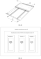
- FIG. 11 is a schematic block diagram of a backplane communication system according to a fifth embodiment of the present disclosure.
- Eddy current is easily formed at a rear of the side inlet air, resulting in a low-speed region.
- the inlet air is concentrated in a middle slot, and an air volume in a side slot is low.
- a negative pressure of the side inlet air may lead to generation of heat recirculation inside a cabinet, which may further affect heat dissipation of the side slot.
- a first embodiment of the present disclosure relates to a heat dissipation subrack.
- the heat dissipation subrack includes a cabinet body defining an accommodating space.
- the cabinet body defines an air inlet, two air supplementing openings respectively disposed on both sides of the air inlet, and an air outlet.
- the accommodating space includes an air inlet region directly facing the air inlet and the two air supplementing openings, and a heat source region communicatively coupled to the air inlet region to allow airflow therebetween.
- the air inlet has a first opening direction
- each of the two air supplementing openings has a second opening direction. The first opening direction and the second opening direction intersect in the air inlet region.
- the cabinet body includes baffles disposed in the air inlet region and spaced apart from one another.
- Each of the baffles includes two wind shielding surfaces respectively facing the two air supplementing openings.
- Airflow passages facing the air inlet and communicatively coupling the air inlet region with the heat source region to allow airflow therebetween are respectively defined between each two adjacent baffles as well as between one of inner walls of the cabinet body and a baffle adjacent to the one of the inner walls of the cabinet body.
- the heat dissipation subrack defines the air inlet for introducing front inlet air and the air supplementing openings for introducing side inlet air.
- the baffles are provided at a junction (that is, a junction of an opening direction of the air inlet and an opening direction of the air supplementing openings, i.e., in the air inlet region) of the front inlet air and the side inlet air. Since the baffle has the wind shielding surfaces facing the air supplementing openings, the wind shielding surfaces may block a part of airflow of the side inlet air from the air supplementing openings, and introduce the part of the airflow to the heat source region via the airflow passage on one side of the baffle.
- the airflow of the side inlet air may be blocked by the multiple baffles disposed at intervals in turn and shunted to one or more airflow passages that are closest to, slightly farther, and farther from the edge of the heat dissipation subrack in turn, which may have following effects.
- a heat dissipation subrack 10 in embodiments includes a cabinet body 11 , an air inlet 12 , air supplementing openings 13 , an air outlet 14 , and baffles 15 located in the cabinet body 11 .
- the air inlet 12 , the air supplementing openings 13 , and the air outlet 14 are defined on the cabinet body 11 .
- the cabinet body 11 includes a front panel 111 and a rear panel 112 that are disposed opposite to each other, two side panels 113 , a bottom panel 114 , and a top panel 115 located above the bottom panel 114 .
- the two side panels 113 are respectively connected with the front panel 111 and the rear panel 112 and are arranged opposite to each other.
- the bottom panel 114 is located below the front panel 111 , the rear panel 112 , and the side panels 113 .
- the front panel 111 , the rear panel 112 , the two side panels 113 , the bottom panel 114 , and the top panel 115 cooperatively define an accommodating space 110 .
- the accommodating space 110 is used for accommodating a communication backplane (not illustrated in the figure) provided with at least one heating element.
- the air inlet 12 is defined on the front panel 111 and is used for introducing the front inlet air from a front (a side of the front panel 111 ) of the cabinet body 11 so as to perform heat dissipation on the at least one heating element in the accommodating space 110 .
- upward and downward directions are Z-axis directions (the upward direction is a Z-axis positive direction)
- leftward and rightward directions are Y-axis directions
- the rightward direction is a Y-axis positive direction
- directions perpendicular to a surface of the figure are X-axis directions (no X-axis is illustrated in FIG.
- an opening direction of the air inlet 12 is the Y-axis direction (hereinafter referred to as a first opening direction) illustrated in FIG. 2 .
- the air inlet 12 is disposed adjacent to the bottom panel 114 . That is, when the cabinet body 11 is placed horizontally (in a vertical direction perpendicular to a horizontal plane, the bottom panel 114 is located below the top panel 115 ), the air inlet 12 is defined at the bottom of the front panel 111 .
- the two air supplementing openings 13 are located on both sides of the air inlet 12 and are respectively defined on the two opposite side panels 113 .
- the air supplementing opening 13 is used for introducing side inlet air from a side (a side of the side panel 113 ) of the cabinet body 11 , to supplement the front inlet air, which may increase airflow entering the accommodating space 110 , thereby improving the heat dissipation effect.
- FIG. 1 In FIG.
- the upward and downward directions are the Z-axis directions (the upward direction is the Z-axis positive direction), the leftward and rightward directions are X-axis directions (the rightward direction is the X-axis positive direction), and directions perpendicular to the surface of the figure are Y-axis directions (no Y-axis is illustrated in FIG. 2 , and a direction that is perpendicular to the surface of the figure and inward is the Y-axis positive direction).
- an opening direction of the air supplementary opening 13 is the X-axis direction (hereinafter referred to as a second opening direction) illustrated in FIG. 1 .
- the first opening direction of the air inlet 12 and the second opening direction of the air supplementing opening 13 intersect in an air inlet region 1101 .
- the front inlet air introduced from the air inlet 12 and the side inlet air introduced from the supplementary air inlets 13 may meet in the air inlet region 1101 .
- the two air supplementing openings 13 are disposed adjacent to the bottom panel 114 . It is to be noted that, in actual use, if it is necessary to ensure that airflow introduction positions of the side inlet air are symmetrical, the two air supplementing openings 13 may be disposed opposite to each other.
- the accommodating space 110 includes the air inlet region 1101 directly facing the air inlet 12 and the two air supplementing openings 13 , and a heat source region 1102 communicatively coupled to the air inlet region 1101 to allow airflow therebetween.
- the air inlet region 1101 is disposed adjacent to the bottom panel 114 .
- the heat source region 1102 is located above the air inlet region 1101 in the vertical direction perpendicular to the horizontal plane.
- the air outlet 14 communicates with the air inlet 12 and the air supplementing openings 13 via the heat source region 1102 and the air inlet region 1101 in turn, thereby discharging hot airflow which is obtained after airflow enters the accommodating space 110 via the air inlet 12 and the air supplementing openings 13 and then heat exchange is conducted with air from the heating element.
- the air outlet 14 is defined at the top of the cabinet body.
- the air outlet 14 may be defined on any of the top panel 115 , the two side panels 113 , the front panel 111 , and the rear panel 112 .
- one air outlet 14 is defined.
- the air outlet 14 is defined on the rear panel 112 and adjacent to the top panel 115 , that is, the air outlet is defined at the top of the cabinet body 11 .
- each of the baffles 15 includes two wind shielding surfaces 150 respectively facing the two air supplementary openings 13 .
- An airflow passage 151 facing the air inlet 12 is defined between each two adjacent baffles 15 , and an airflow passage 151 facing the air inlet 12 is also defined between one of inner walls (not illustrated in the figure, e.g., a side of the side panel 113 facing the accommodating space 110 ) of the cabinet body 11 and the baffle 15 adjacent to the one of the inner walls of the cabinet body 11 , so that the airflow passage 151 communicates the air inlet region 1101 and the heat source region 1102 .
- the wind shielding surface 150 may block a part of the airflow of the side inlet air from the air supplementing opening 13 and introduce the part of the airflow to the heat source region 1102 through the airflow passage 151 located on one side of the baffle 15 . In this way, during the airflow of the side inlet air (along X-axis positive and negative directions illustrated in FIG.
- the airflow of the side inlet air may be blocked by the multiple baffles 15 disposed at intervals in turn and shunted to the airflow passages 151 which are closest to, slightly farther, and farther from the edge of the heat dissipation subrack 10 .
- the airflow volume of the side inlet air reaching the middle of the heat dissipation subrack 10 may be reduced, and impact of the side inlet air on the front inlet air in the middle of the heat dissipation subrack 10 is alleviated, thereby alleviating squeezing of the side inlet air on the front inlet air.
- the eddy current may be reduced, and the low-speed airflow region caused by the eddy current on the heat dissipation effect may be reduced.
- the partial airflow shunted increases the volume of inlet air flowing into the heat source region 1102 from the edge of the heat dissipation subrack 10 , the uneven heat dissipation caused by the airflow concentrated in the middle of the heat dissipation subrack 10 may be improved. Due to an increased inlet air volume at the edge of the heat dissipation subrack 10 , the negative pressure caused by insufficient airflow at the edge of the heat dissipation subrack 10 may be alleviated, and the heat recirculation caused by the negative pressure may be alleviated, such that the heat dissipation effect may be effectively improved.
- FIG. 5 is a comparison diagram of air inlet flow fields in the related art and in embodiments.
- the left side in FIG. 5 illustrates an air inlet flow field of an existing heat dissipation subrack, and the right side in FIG. 5 illustrates an air inlet flow field of the heat dissipation subrack of the present embodiments.
- a density of black dots represents a density of gas molecules or an airflow volume. It can be seen that with the baffle of the heat dissipation subrack in embodiments, distribution of the flow field may be significantly improved, and the eddy current may be reduced, such that the low-speed region at the edge of the cabinet body may be significantly improved. Experimental data shows that the heat dissipation capability of the heat dissipation subrack provided in embodiments can be improved by 30-70%.
- the multiple baffles 15 blocks and shunts the side inlet air through the wind shielding surfaces 150 , and guides the front inlet air and the shunted side inlet air through the airflow passages 151 defined by the baffles disposed at intervals. Therefore, on the premise that the wind shielding surfaces 150 (i.e., a panel surface) of the multiple baffles 15 face the air supplementing openings 13 , and there are gaps between the multiple baffles 15 for airflow to pass through, the baffles 15 may be designed to have different structures according to different considerations, such as process requirements and customer needs.
- the multiple baffles 15 may be disposed in parallel to each other or obliquely. In embodiments, the multiple baffles are arranged in parallel. In this way, the airflow passages 151 defined between the baffles 15 are relatively regular (i.e., each airflow passage has a constant width), which ensures that the airflow volume at each position of the airflow passage 151 is substantially equal, so that the airflow distribution of airflow in each airflow passage 151 is relatively uniform.
- the multiple baffles 15 may also be parallel to the first opening direction.
- an extending direction of the baffle 15 coincides with a direction of inlet airflow of the air inlet 12 , which may reduce a wind resistance of the inlet airflow of the air inlet 12 flowing to the airflow passage 151 and keep the airflow unobstructed.
- the multiple baffles 15 may also be disposed to be perpendicular to the second opening direction. In this way, the wind shielding surfaces 150 of the baffles 15 are perpendicular to an inlet airflow direction of the air supplementing openings, which may enhance blocking and shunting effects on the side inlet air.
- a width of each of the airflow passages 151 in the second opening direction may be set to be the same, so that an air volume of each of the airflow passages 151 is more uniform.
- the airflow passages 151 have different widths in the second opening direction.
- the airflow passage 151 located at the central region of the air inlet region 1101 has a first width in the second opening direction
- the at least one airflow passage 151 located at a non-central region of the air intake region 1101 has a second width in the second opening direction, where the first width is larger than the second width.
- baffles 15 may be set to have a same size (i.e., the wind shielding surfaces 150 have a same area). In this way, baffles 15 may be manufactured in batches and assembled in different positions in the air inlet region 1101 to achieve corresponding wind-shielding and diversion effects.
- areas of the wind shielding surfaces 150 of the multiple baffles 15 increases sequentially along a direction (i.e., a direction from both sides of the cabinet body 11 toward the center of the cabinet body 11 ) away from the air supplementary openings 13 . Since the central region of the air inlet region 1101 is far away from the air supplementing openings 13 , and airflow received from the air supplementing openings is relatively small. Thus, increasing the area of the wind shielding surface 150 at the central region may enable to receive and guide the airflow of the side inlet air in a larger range (along the Z-axis direction), thereby avoiding that airflow at the central region of the air inlet region 1101 is relatively small.
- the multiple baffles 15 may have the same length in the first opening direction and different heights in a direction (i.e., the Z-axis direction) perpendicular to the first opening direction and the second opening direction, so that the baffles 15 may have wind shielding surfaces 150 of different sizes.
- the multiple baffles 15 are symmetrically disposed on both sides of the airflow passage 151 located at the central region of the air inlet region 1101 .
- the accommodating space 110 may further include a fan region 1103 for accommodating a fan and adjacent to the air outlet 14 .
- An air inlet side of the fan region 1103 faces the heat source region, and an air outlet side of the fan region 1103 faces the air outlet 14 , so that hot airflow in the heat source region may be driven by the fan disposed in the fan region 19 to flow out through the air outlet 14 .
- the heat dissipation subrack 20 of the second embodiment is substantially the same as the heat dissipation subrack 10 of the first embodiment.
- the heat dissipation subrack 20 of the second embodiment also includes a cabinet body 11 , an air inlet (not illustrated in the figure), air supplementing openings 13 , and an air outlet (not illustrated in the figure), and a baffle 15 located in the cabinet body 11 , where the air inlet, the air supplementing openings 13 , and the air outlet are defined on the cabinet body.
- the heat dissipation subrack 20 and the heat dissipation subrack 10 differ in that the heat dissipation subrack 20 of the second embodiment further includes a perforated panel 16 illustrated in FIG. 7 .
- the heat source region 1102 is disposed adjacent to the air inlet region 1101 .
- the perforated panel 16 is disposed at a junction of the air inlet region 1101 and the heat source region 1102 .
- the perforated panel 16 defines at least one through hole 160 .
- An upper end of the through hole 160 communicates with the heat source region 1102 and a lower end of the through hole 160 communicates with the air inlet region 1101 .
- the perforated panel 16 is disposed directly facing the airflow passage 151 located at the central region of the air inlet region 1101 .
- a size of the perforated panel 16 in the first opening direction is the same as that of the airflow passage 151 located at the central region of the air inlet region 1101 in the first opening direction and a size of the perforated panel 16 in the second opening direction is the same as that of the airflow passage 151 located at the central region of the air inlet region 1101 in the second opening direction.
- the perforated panel 16 covers the airflow passage 151 located at the central region of the air inlet region 1101 .
- the upper end of the through hole 160 communicates with the heat source region 1102 and the lower end of the through hole 160 communicates with the airflow passage 151 located at the central region of the air inlet region 1101 .
- an air volume at the central region of the cabinet body 11 may be adjusted by controlling a size of each through hole 160 and an opening ratio of the through holes 160 .
- the perforated panel 16 may also traverse an entire horizontal cross-section of the cabinet body 11 , so as to cover all the airflow passages 151 .
- a group of the through holes 160 are defined in a corresponding region of the perforated panel 16 directly facing the airflow passage 151 .
- the size and the opening ratio of the through holes are respectively set for each group of through holes 160 , so that airflow volume at each position of the junction of the heat source region 1102 and the air inlet region 1101 may be adjusted.
- the cabinet body 11 further includes a guide rail 18 disposed in the heat source region 1102 and located above the guide rail 17 .
- the guide rail 17 and the guide rail 18 are disposed opposite to each other, to cooperatively fix the backplane. It can be understood that, there may be multiple guide rails 17 and guide rails 18 , and the multiple guide rails 17 and the multiple guide rails 18 are in one-to-one correspondence, so as to fix multiple backplanes.
- the heat dissipation subrack 30 of the third embodiment is substantially the same as the heat dissipation subrack 10 of the first embodiment.
- the heat dissipation subrack 30 also includes a cabinet body 11 , an air inlet (not illustrated in the figure), air supplementing openings 13 , an air outlet (not illustrated in the figure), and baffles 15 located in the cabinet body 11 .
- the air inlet, the air supplementing openings 13 , and the air outlet are disposed on the cabinet body.
- the heat dissipation subrack 30 and the heat dissipation subrack 10 differ in that the baffles 15 of the third embodiment isolate the multiple airflow passages 151 from each other, the air inlet (not illustrated) communicates with each of the airflow passages 151 , and the air supplementing openings 13 communicates with at least part of the airflow passages 151 located at the non-central region of the air inlet region 1101 .
- the multiple airflow passages 151 are completely isolated, such that squeezing of airflow of the air supplementing openings 13 on airflow of the air inlet located at the central region of the air inlet region 1101 may be completely eliminated.
- the heat dissipation subrack 30 in the third embodiment may also be modified from the heat dissipation subrack 20 of the second embodiment.
- the baffles 15 are provided as follows.
- the airflow passages 151 are isolated from each other by the baffles 15 , the air inlet (not illustrated) communicates with each of the airflow passages 151 , and the air supplementing openings 13 communicates with at least the part of the airflow passages 151 located at the non-central region of the air inlet region 1101 .
- a heat dissipation cabinet 40 is provided.
- the heat dissipation cabinet 40 includes two heat dissipation subracks 10 as described in the first embodiment.
- the cabinet body 11 of one of the two heat dissipation subracks 10 is stacked on the cabinet body 11 of the other of the two heat dissipation subracks 10 .
- the two cabinet bodies 11 in embodiments are arranged in opposite directions, so that structures of the two cabinet bodies 11 are symmetrical.
- neither of the two cabinet bodies 11 is provided with the bottom panel 114 described in the first embodiment, and top panels 115 of the two cabinet bodies 11 are far away from each other.
- an air supplementing region 41 may also be defined between the two cabinet bodies 11 (that is, between the two air inlet regions 1101 ).
- the air supplementing region 41 communicates with the air inlet regions 1101 of the two cabinet bodies 11 , respectively.
- the air supplementing region 41 includes multiple air inlet passages 410 as illustrated in FIG. 10 .
- the multiple air inlet passages 410 communicate with at least one of airflow passages 151 of multiple cabinet bodies 11 , respectively.
- the heat dissipation cabinet 40 may further include a heat dissipation region 42 that is defined between the two cabinet bodies 11 and adjacent to the air supplementing region 41 .
- the heat dissipation region 42 includes an airflow passage 420 , and an inlet port 421 and an exhaust port 422 that communicate with the air passage 420 , respectively.
- the inlet port 421 may be set to have a second opening direction
- the exhaust port 422 may be set to have a first opening direction (which is the same as an opening direction of the air outlet 14 ).
- the airflow passage 420 is substantially L-shaped.
- the heat dissipation region 42 may be used for accommodating a single board of the switch and realizing heat dissipation for the single board of the switch.
- each of the two heat dissipation subracks 10 of the heat dissipation cabinet 40 may be replaced by the heat dissipation subrack 20 of the second embodiment or the heat dissipation subrack 30 of the third embodiment, and various structures replaced are not repeated herein.
- a backplane communication system 50 includes the heat dissipation subrack 10 , the heat dissipation subrack 20 , the heat dissipation subrack 30 , or the heat dissipation cabinet 40 defining the accommodating space 110 and described in the foregoing embodiments, multiple backplanes 51 disposed inside the accommodating space 110 , and multiple heating elements 52 , where each of the multiple heating elements 52 is disposed on a corresponding backplane 51 .
Landscapes
- Engineering & Computer Science (AREA)
- Microelectronics & Electronic Packaging (AREA)
- Computer Networks & Wireless Communication (AREA)
- Physics & Mathematics (AREA)
- Thermal Sciences (AREA)
- Aviation & Aerospace Engineering (AREA)
- Health & Medical Sciences (AREA)
- Toxicology (AREA)
- Cooling Or The Like Of Electrical Apparatus (AREA)
Abstract
Description
-
- 1. Since the airflow of the side inlet air flowing to the heat dissipation subrack is shunted to the airflow passages at the edge of the heat dissipation subrack and then enter the heat source region, an airflow volume of the side inlet air reaching the middle of the heat dissipation subrack may be reduced, and impact of the side inlet air on the front inlet air in the middle of the heat dissipation subrack may be alleviated, thereby alleviating squeezing of the side inlet air on the front inlet air. In addition, the eddy current may be reduced, and influence of a low-speed airflow region caused by the eddy current on the heat dissipation effect may be reduced.
- 2. Since partial airflow shunted increases the volume of the inlet air flowing into the heat source region from the edge of the heat dissipation subrack, uneven heat dissipation caused by the airflow concentrated in the middle of the heat dissipation subrack may be improved.
- 3. Due to an increased inlet air volume at the edge of the heat dissipation subrack, a negative pressure caused by insufficient airflow at the edge of an existing heat dissipation subrack may be alleviated, and the heat recirculation caused by the negative pressure may be alleviated. Thus, heat dissipation effect of communication equipment may be effectively improved.
Claims (19)
Applications Claiming Priority (3)
| Application Number | Priority Date | Filing Date | Title |
|---|---|---|---|
| CN201911075828.2 | 2019-11-06 | ||
| CN201911075828.2A CN112770191B (en) | 2019-11-06 | 2019-11-06 | A heat dissipation plug box, heat dissipation cabinet and backplane communication system |
| PCT/CN2020/125952 WO2021088771A1 (en) | 2019-11-06 | 2020-11-02 | Heat dissipation subrack, heat dissipation cabinet and backboard communication system |
Publications (2)
| Publication Number | Publication Date |
|---|---|
| US20220386505A1 US20220386505A1 (en) | 2022-12-01 |
| US12096592B2 true US12096592B2 (en) | 2024-09-17 |
Family
ID=75692779
Family Applications (1)
| Application Number | Title | Priority Date | Filing Date |
|---|---|---|---|
| US17/773,596 Active 2041-06-21 US12096592B2 (en) | 2019-11-06 | 2020-11-02 | Heat dissipation subrack, heat dissipation cabinet, and backplane communication system |
Country Status (3)
| Country | Link |
|---|---|
| US (1) | US12096592B2 (en) |
| CN (1) | CN112770191B (en) |
| WO (1) | WO2021088771A1 (en) |
Families Citing this family (4)
| Publication number | Priority date | Publication date | Assignee | Title |
|---|---|---|---|---|
| CN116321822A (en) * | 2021-12-02 | 2023-06-23 | 中兴智能科技南京有限公司 | Air guide sub-boxes and cabinets |
| CN116261315B (en) * | 2023-05-12 | 2023-07-11 | 合肥创科电子工程科技有限责任公司 | Cabinet temperature regulation control system |
| CN116916552B (en) * | 2023-09-13 | 2024-05-31 | 深圳荣耀智能机器有限公司 | Multi-runner tuyere and multi-runner heating equipment |
| CN117560872B (en) * | 2023-10-31 | 2025-09-16 | 厦门科华数能科技有限公司 | Electrical cabinet |
Citations (17)
| Publication number | Priority date | Publication date | Assignee | Title |
|---|---|---|---|---|
| WO1987000261A1 (en) | 1985-07-10 | 1987-01-15 | Archer Virgil L | Air slot cooking grill |
| EP0752561A1 (en) | 1995-07-04 | 1997-01-08 | Bosch-Siemens HausgerÀ¤te GmbH | Cooking oven |
| US20050281014A1 (en) * | 2004-06-21 | 2005-12-22 | Carullo Thomas J | Surrogate card for printed circuit board assembly |
| US20070258211A1 (en) * | 2004-11-16 | 2007-11-08 | Fujitsu Limited | Communication apparatus and rack structure |
| US20080094799A1 (en) * | 2006-10-19 | 2008-04-24 | Cisco Technology, Inc. | Method and apparatus for providing thermal management in an electronic device |
| US20090061755A1 (en) * | 2007-08-28 | 2009-03-05 | Panduit Corp. | Intake Duct |
| CN101790291A (en) | 2009-01-23 | 2010-07-28 | 华为技术有限公司 | Insertion box and heat dissipating method thereof |
| US8257156B2 (en) * | 2006-03-20 | 2012-09-04 | Flextronics Ap, Llc | Increasing air inlet/outlet size for electronics chassis |
| CN203040083U (en) | 2012-11-23 | 2013-07-03 | 杭州华三通信技术有限公司 | Air channel guiding device |
| US20140138069A1 (en) * | 2012-11-22 | 2014-05-22 | Huawei Technologies Co., Ltd. | Heat dissipation system |
| CN105451517A (en) | 2015-11-30 | 2016-03-30 | 中国电子科技集团公司第二十八研究所 | Forced air exhaust type radiating electronic case |
| US20170112023A1 (en) * | 2015-10-19 | 2017-04-20 | Hon Hai Precision Industry Co., Ltd. | Cooling system for data center |
| CN107282583A (en) | 2017-08-08 | 2017-10-24 | 倚世节能科技(上海)有限公司 | A kind of mend wind passage of ventilation equipment |
| CN107506004A (en) | 2017-09-26 | 2017-12-22 | 天津七所精密机电技术有限公司 | Cabinet is reinforced using the 4U of optimization Duct design |
| CN108541196A (en) | 2018-05-31 | 2018-09-14 | 烽火通信科技股份有限公司 | A kind of heat dissipation water conservancy diversion cabinet |
| CN109114856A (en) | 2018-07-09 | 2019-01-01 | 青岛海尔特种电冰柜有限公司 | Horizontal type wind-cooling refrigerator |
| CN208581445U (en) | 2018-08-03 | 2019-03-05 | 联想(北京)有限公司 | Air ducting and electronic equipment |
Family Cites Families (4)
| Publication number | Priority date | Publication date | Assignee | Title |
|---|---|---|---|---|
| CN101795546B (en) * | 2009-02-04 | 2012-07-04 | 华为技术有限公司 | Subrack and heat radiating method thereof |
| CN106304770A (en) * | 2015-06-03 | 2017-01-04 | 中兴通讯股份有限公司 | Subrack and subrack modular construction |
| CN208480203U (en) * | 2018-07-31 | 2019-02-05 | 江苏乐希科技有限公司 | Distributed heat removal air channel structure for energy storage cabinet |
| CN109817858B (en) * | 2019-01-25 | 2024-07-12 | 北京海博思创科技股份有限公司 | battery box |
-
2019
- 2019-11-06 CN CN201911075828.2A patent/CN112770191B/en active Active
-
2020
- 2020-11-02 US US17/773,596 patent/US12096592B2/en active Active
- 2020-11-02 WO PCT/CN2020/125952 patent/WO2021088771A1/en not_active Ceased
Patent Citations (17)
| Publication number | Priority date | Publication date | Assignee | Title |
|---|---|---|---|---|
| WO1987000261A1 (en) | 1985-07-10 | 1987-01-15 | Archer Virgil L | Air slot cooking grill |
| EP0752561A1 (en) | 1995-07-04 | 1997-01-08 | Bosch-Siemens HausgerÀ¤te GmbH | Cooking oven |
| US20050281014A1 (en) * | 2004-06-21 | 2005-12-22 | Carullo Thomas J | Surrogate card for printed circuit board assembly |
| US20070258211A1 (en) * | 2004-11-16 | 2007-11-08 | Fujitsu Limited | Communication apparatus and rack structure |
| US8257156B2 (en) * | 2006-03-20 | 2012-09-04 | Flextronics Ap, Llc | Increasing air inlet/outlet size for electronics chassis |
| US20080094799A1 (en) * | 2006-10-19 | 2008-04-24 | Cisco Technology, Inc. | Method and apparatus for providing thermal management in an electronic device |
| US20090061755A1 (en) * | 2007-08-28 | 2009-03-05 | Panduit Corp. | Intake Duct |
| CN101790291A (en) | 2009-01-23 | 2010-07-28 | 华为技术有限公司 | Insertion box and heat dissipating method thereof |
| US20140138069A1 (en) * | 2012-11-22 | 2014-05-22 | Huawei Technologies Co., Ltd. | Heat dissipation system |
| CN203040083U (en) | 2012-11-23 | 2013-07-03 | 杭州华三通信技术有限公司 | Air channel guiding device |
| US20170112023A1 (en) * | 2015-10-19 | 2017-04-20 | Hon Hai Precision Industry Co., Ltd. | Cooling system for data center |
| CN105451517A (en) | 2015-11-30 | 2016-03-30 | 中国电子科技集团公司第二十八研究所 | Forced air exhaust type radiating electronic case |
| CN107282583A (en) | 2017-08-08 | 2017-10-24 | 倚世节能科技(上海)有限公司 | A kind of mend wind passage of ventilation equipment |
| CN107506004A (en) | 2017-09-26 | 2017-12-22 | 天津七所精密机电技术有限公司 | Cabinet is reinforced using the 4U of optimization Duct design |
| CN108541196A (en) | 2018-05-31 | 2018-09-14 | 烽火通信科技股份有限公司 | A kind of heat dissipation water conservancy diversion cabinet |
| CN109114856A (en) | 2018-07-09 | 2019-01-01 | 青岛海尔特种电冰柜有限公司 | Horizontal type wind-cooling refrigerator |
| CN208581445U (en) | 2018-08-03 | 2019-03-05 | 联想(北京)有限公司 | Air ducting and electronic equipment |
Non-Patent Citations (1)
| Title |
|---|
| ZTE Corporation, International Search Report with English Translation, PCT/CN2020/125952, Jan. 20, 2021, 6 pgs. |
Also Published As
| Publication number | Publication date |
|---|---|
| CN112770191B (en) | 2025-04-11 |
| CN112770191A (en) | 2021-05-07 |
| US20220386505A1 (en) | 2022-12-01 |
| WO2021088771A1 (en) | 2021-05-14 |
Similar Documents
| Publication | Publication Date | Title |
|---|---|---|
| US12096592B2 (en) | Heat dissipation subrack, heat dissipation cabinet, and backplane communication system | |
| US8526182B2 (en) | Cooling circulation system of server | |
| US11132035B2 (en) | Air directing device | |
| US8120912B2 (en) | Front-to-back cooling system for modular systems with orthogonal midplane configuration | |
| EP2760262B1 (en) | Cooling system | |
| CN102436298B (en) | Heat dissipation equipment and blade server | |
| EP2146563A2 (en) | Airflow/cooling solution for chassis | |
| CN106973542B (en) | Wind-guiding cabinet and communication system | |
| CN203691803U (en) | Plug-in box and terminal | |
| CN102791109A (en) | Cabinet type computer system and cooling structure thereof | |
| US10412855B2 (en) | Air deflection system | |
| CN105392339B (en) | Electrical cabinet | |
| CN204031653U (en) | A kind of rack | |
| CN102984923A (en) | Communication single board and communication device | |
| CN217656288U (en) | Heat dissipation box and distribution equipment thereof | |
| CN113068369B (en) | Air guide assembly, air guide device and cabinet | |
| CN211429854U (en) | Air guide cabinet, air guide device, cabinet and machine room | |
| CN105718006A (en) | Orthogonal heat dissipation case | |
| CN212910521U (en) | Cabinet convenient for heat dissipation of database | |
| CN114144032B (en) | VPX plug-in box, plug-in box group and heat dissipation method thereof | |
| JP2009266914A (en) | Cooling structure of cabinet for storing electric and electronic equipment | |
| CN104640417A (en) | Radiating device and method and cabinet | |
| EP3989690B1 (en) | Communication device | |
| WO2022152088A1 (en) | Temperature control cabinet and communication system | |
| CN222718324U (en) | Driving cabinet and air wall system |
Legal Events
| Date | Code | Title | Description |
|---|---|---|---|
| FEPP | Fee payment procedure |
Free format text: ENTITY STATUS SET TO UNDISCOUNTED (ORIGINAL EVENT CODE: BIG.); ENTITY STATUS OF PATENT OWNER: LARGE ENTITY |
|
| AS | Assignment |
Owner name: ZTE CORPORATION, CHINA Free format text: ASSIGNMENT OF ASSIGNORS INTEREST;ASSIGNOR:WEI, JUN;REEL/FRAME:059745/0669 Effective date: 20220419 |
|
| STPP | Information on status: patent application and granting procedure in general |
Free format text: DOCKETED NEW CASE - READY FOR EXAMINATION |
|
| AS | Assignment |
Owner name: ZTE CORPORATION, CHINA Free format text: ASSIGNMENT OF ASSIGNORS INTEREST;ASSIGNOR:WEI, JUN;REEL/FRAME:061402/0572 Effective date: 20220419 |
|
| AS | Assignment |
Owner name: ZTE CORPORATION, CHINA Free format text: ASSIGNMENT OF ASSIGNORS INTEREST;ASSIGNOR:WEI, JUN;REEL/FRAME:063777/0025 Effective date: 20220419 |
|
| STPP | Information on status: patent application and granting procedure in general |
Free format text: NON FINAL ACTION MAILED |
|
| STPP | Information on status: patent application and granting procedure in general |
Free format text: RESPONSE TO NON-FINAL OFFICE ACTION ENTERED AND FORWARDED TO EXAMINER |
|
| STPP | Information on status: patent application and granting procedure in general |
Free format text: NOTICE OF ALLOWANCE MAILED -- APPLICATION RECEIVED IN OFFICE OF PUBLICATIONS |
|
| AS | Assignment |
Owner name: XI'AN ZHONGXING NEW SOFTWARE CO., LTD., CHINA Free format text: ASSIGNMENT OF ASSIGNORS INTEREST;ASSIGNOR:ZTE CORPORATION;REEL/FRAME:068175/0628 Effective date: 20240726 |
|
| STPP | Information on status: patent application and granting procedure in general |
Free format text: PUBLICATIONS -- ISSUE FEE PAYMENT VERIFIED |
|
| STCF | Information on status: patent grant |
Free format text: PATENTED CASE |