US12092125B2 - Pump device comprising a radial bearing - Google Patents
Pump device comprising a radial bearing Download PDFInfo
- Publication number
- US12092125B2 US12092125B2 US17/673,450 US202217673450A US12092125B2 US 12092125 B2 US12092125 B2 US 12092125B2 US 202217673450 A US202217673450 A US 202217673450A US 12092125 B2 US12092125 B2 US 12092125B2
- Authority
- US
- United States
- Prior art keywords
- rotor
- bearing
- stator
- region
- cavity
- Prior art date
- Legal status (The legal status is an assumption and is not a legal conclusion. Google has not performed a legal analysis and makes no representation as to the accuracy of the status listed.)
- Active, expires
Links
Images


Classifications
-
- F—MECHANICAL ENGINEERING; LIGHTING; HEATING; WEAPONS; BLASTING
- F04—POSITIVE - DISPLACEMENT MACHINES FOR LIQUIDS; PUMPS FOR LIQUIDS OR ELASTIC FLUIDS
- F04D—NON-POSITIVE-DISPLACEMENT PUMPS
- F04D29/00—Details, component parts, or accessories
- F04D29/04—Shafts or bearings, or assemblies thereof
- F04D29/046—Bearings
-
- F—MECHANICAL ENGINEERING; LIGHTING; HEATING; WEAPONS; BLASTING
- F04—POSITIVE - DISPLACEMENT MACHINES FOR LIQUIDS; PUMPS FOR LIQUIDS OR ELASTIC FLUIDS
- F04D—NON-POSITIVE-DISPLACEMENT PUMPS
- F04D13/00—Pumping installations or systems
- F04D13/02—Units comprising pumps and their driving means
- F04D13/06—Units comprising pumps and their driving means the pump being electrically driven
- F04D13/0606—Canned motor pumps
- F04D13/0626—Details of the can
-
- F—MECHANICAL ENGINEERING; LIGHTING; HEATING; WEAPONS; BLASTING
- F04—POSITIVE - DISPLACEMENT MACHINES FOR LIQUIDS; PUMPS FOR LIQUIDS OR ELASTIC FLUIDS
- F04D—NON-POSITIVE-DISPLACEMENT PUMPS
- F04D13/00—Pumping installations or systems
- F04D13/02—Units comprising pumps and their driving means
- F04D13/06—Units comprising pumps and their driving means the pump being electrically driven
- F04D13/0606—Canned motor pumps
- F04D13/0633—Details of the bearings
-
- F—MECHANICAL ENGINEERING; LIGHTING; HEATING; WEAPONS; BLASTING
- F04—POSITIVE - DISPLACEMENT MACHINES FOR LIQUIDS; PUMPS FOR LIQUIDS OR ELASTIC FLUIDS
- F04D—NON-POSITIVE-DISPLACEMENT PUMPS
- F04D29/00—Details, component parts, or accessories
- F04D29/18—Rotors
- F04D29/22—Rotors specially for centrifugal pumps
-
- F—MECHANICAL ENGINEERING; LIGHTING; HEATING; WEAPONS; BLASTING
- F04—POSITIVE - DISPLACEMENT MACHINES FOR LIQUIDS; PUMPS FOR LIQUIDS OR ELASTIC FLUIDS
- F04D—NON-POSITIVE-DISPLACEMENT PUMPS
- F04D29/00—Details, component parts, or accessories
- F04D29/40—Casings; Connections of working fluid
- F04D29/42—Casings; Connections of working fluid for radial or helico-centrifugal pumps
- F04D29/4206—Casings; Connections of working fluid for radial or helico-centrifugal pumps especially adapted for elastic fluid pumps
-
- F—MECHANICAL ENGINEERING; LIGHTING; HEATING; WEAPONS; BLASTING
- F04—POSITIVE - DISPLACEMENT MACHINES FOR LIQUIDS; PUMPS FOR LIQUIDS OR ELASTIC FLUIDS
- F04D—NON-POSITIVE-DISPLACEMENT PUMPS
- F04D9/00—Priming; Preventing vapour lock
- F04D9/001—Preventing vapour lock
- F04D9/002—Preventing vapour lock by means in the very pump
- F04D9/003—Preventing vapour lock by means in the very pump separating and removing the vapour
-
- F—MECHANICAL ENGINEERING; LIGHTING; HEATING; WEAPONS; BLASTING
- F05—INDEXING SCHEMES RELATING TO ENGINES OR PUMPS IN VARIOUS SUBCLASSES OF CLASSES F01-F04
- F05D—INDEXING SCHEME FOR ASPECTS RELATING TO NON-POSITIVE-DISPLACEMENT MACHINES OR ENGINES, GAS-TURBINES OR JET-PROPULSION PLANTS
- F05D2240/00—Components
- F05D2240/60—Shafts
- F05D2240/61—Hollow
Definitions
- the present invention relates to a pump device.
- Pump devices are known from the prior art, in which a drive sets a rotor in rotation relative to a stator.
- a shaft runs inside the rotor, which connects the rotor to the drive.
- the radial support takes place by means of a plain bearing, which is disposed on the shaft.
- An axial support takes place in an intake pipe or on an end face of the radial bearing.
- a pump device within the meaning of this description can also be referred to as a pump or pump unit.
- the pump device can be suitable in particular for a fluid circuit in a motor vehicle. It comprises a housing, a drive, a rotor, a stator, and a radial bearing.
- a radial bearing is understood to mean, in particular, a bearing, for example, a plain bearing, which restricts movement of the rotor in radial directions or even makes it impossible.
- movements of the rotor are restricted or made impossible by the radial bearing in all radial directions.
- the housing can also be referred to as a pump housing.
- the housing has an inlet.
- the rotor comprises an impeller wheel.
- the drive is designed to set the rotor in rotation relative to the stator. This can occur, for example, electromagnetically.
- the inlet is fluidly connected to the impeller wheel.
- a fluidic connection is understood in particular to mean that a fluid can flow or stream from one component, here the inlet, to the other component, here the impeller wheel. In this case, this flow can be forced by means of fluid-conducting means, such as, for example, channels, lines, pipes, and/or bores.
- the rotor has a rotor cavity.
- Said rotor cavity can be used, for example, to allow air to escape from the pump device.
- the escape of air from the pump device can also be referred to as venting and is necessary because the pumped fluid displaces air.
- a section of the stator projects into the rotor cavity.
- the radial bearing is situated in the rotor cavity between the section of the stator and the rotor.
- the radial bearing can thus be situated around the section of the stator and thereby between the stator and the rotor. Due to the arrangement of the radial bearing, the rotor is supported in the radial direction. At the same time, the rotor cavity is available for venting, because no shaft protrudes through it.
- the stator can have a stator cavity.
- the stator cavity can be surrounded by the section of the stator and thus project into the rotor cavity.
- the stator cavity can be fluidly connected to the rotor cavity.
- the stator cavity can merge into the rotor cavity.
- the stator cavity can also be used for venting, for example. In this case, the displaced air can flow, for example, from the stator cavity via the rotor cavity to a vent outlet.
- the stator cavity and/or the rotor cavity can be free of a shaft.
- the stator cavity and the rotor cavity are particularly well suited for ventilation, because the air flow is not disrupted by a shaft.
- the rotor is driven electromagnetically.
- the pump device can comprise a vent outlet.
- this is understood to mean in particular an outlet through which the displaced air can be discharged to an area surrounding the pump device.
- the vent outlet can be fluidly connected to the rotor cavity so that air can flow from the stator cavity through the rotor cavity to the vent outlet.
- the section of the stator can project into the rotor cavity at a first end of the rotor.
- the impeller wheel can be disposed at a second end of the rotor. The second end can be disposed opposite the first end.
- the radial bearing can have a first and a second bearing region.
- the radial bearing can have a first outer diameter in the first bearing region and a second outer diameter in the second bearing region.
- the second outer diameter in this case can be smaller than the first outer diameter.
- the two bearing sections can be connected, for example, to one another via a third bearing region, wherein the third bearing region has a sloping outer surface.
- the outer diameter is understood to mean in particular the diameter of the particular component on its outer side. In the case of the radial bearing, the outer side can face the rotor.
- the bearing regions with different outer diameters can improve the support.
- the section of the stator can have a first and a second region.
- the section can have a third outer diameter in the first region and a fourth outer diameter in the second region.
- the fourth outer diameter in this case can be smaller than the third outer diameter. It is also possible that the third outer diameter is smaller than the first outer diameter and the fourth outer diameter is smaller than the second outer diameter.
- the inner diameter of the section can be constant.
- the different outer diameters of the section of the stator can be advantageous for a better support of the rotor.
- the section in the transition from the first region to the second region has a circumferential collar on which the radial bearing is supported in the axial direction of the rotor.
- the first bearing region and the first region of the section can partially overlap.
- the second bearing region can partially overlap with the second region of the section.
- the pump device can comprise a bearing situated between the impeller wheel and the housing.
- the bearing can be designed for the axial support of the rotor.
- the housing can have an annular groove and the impeller wheel can have an annular projection which projects into the groove.
- a projection and such a groove are described in German patent application DE 10 2019 115 774, which is incorporated herein by reference.
- the projection is referred to as a rim in the patent application.
- the bearing can be situated between the projection and the housing. In particular, the bearing can be disposed in the groove. Due to the arrangement of the bearing described above, gaps between the housing and the bearing can be made particularly small. This increases the efficiency of the pump device. In addition, the bearing has no or only a little effect on the venting of the pump device.
- the bearing can have a ring shape, for example.
- the bearing can be designed for the radial support of the rotor. For example, it can therefore be designed both for the axial and for the radial support of the rotor.
- the additional radial support provided by the bearing enables a simpler design of the radial bearing, because fewer forces act on the radial bearing.
- the radial bearing can thus be smaller and have a relatively simple shape as a ring.
- the section of the stator that protrudes into the rotor cavity can be made shorter, so that ventilation is further improved.
- the bearing may have an L-shaped cross-sectional area.
- One leg of the L-shape can contribute to the axial support and the other leg of the L-shape to the radial support of the rotor.
- the pump device can comprise an outlet.
- the impeller wheel can be designed to cause a fluid flow from the inlet to the outlet when the rotor is set in rotation by the drive.
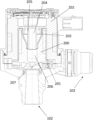
- FIG. 1 shows a schematic perspective view of a pump device according to one embodiment of the invention
- FIG. 2 shows a schematic sectional view of a pump device according to one embodiment of the invention.
- FIG. 3 shows a schematic sectional view of a pump device according to one embodiment of the invention.
- Pump device 100 comprises a housing 101 , an inlet 102 , and an outlet 103 .
- Pump device 100 is designed to be connected to a fluid circuit with inlet 102 and outlet 103 . In operation, pump device 100 causes a flow of the fluid in the fluid circuit.
- FIG. 2 comprises an inlet 102 , an outlet 103 , a rotor 200 with an impeller wheel 201 and with a rotor cavity 206 , a stator 202 with a section 205 and with a stator cavity 204 , a radial bearing 203 , and a bearing 207 .
- Section 205 projects into rotor cavity 206 .
- Stator cavity 204 is disposed in section 205 and is fluidly connected to rotor cavity 206 .
- Radial bearing 203 is disposed between section 205 and rotor 200 .
- Radial bearing 203 has a larger outer diameter in a first region than in a second region.
- the outer diameter of radial bearing 203 tapers continuously between the first region and the second region.
- This shape of radial bearing 203 is particularly advantageous for a good radial support of rotor 200 .
- the shape is particularly advantageous for good lubrication of radial bearing 203 .
- Bearing 207 is used for the axial support of rotor 200 .
- the bearing is arranged in a groove of the housing between a projection of impeller wheel 201 and the housing and is formed annular. At this position, bearing 207 has little or even no effect on both the fluid flow and the ventilation flow.
- Stator cavity 204 and rotor cavity 206 are free of a shaft. As a result, rotor cavity 206 and stator cavity 204 can be used particularly well for venting pump device 100 . The air can be routed through stator cavity 204 and rotor cavity 206 to a vent outlet through which it then exits pump device 100 into the environment.
- rotor 200 with impeller wheel 201 is set in rotation relative to stator 202 by a drive (not shown).
- a fluid for example, a working fluid of a motor vehicle, is drawn in through inlet 102 and conveyed to outlet 103 by means of impeller wheel 201 .
- the air displaced thereby flows through stator cavity 204 and rotor cavity 206 to a vent outlet.
- the embodiment shown in FIG. 3 differs from the embodiment shown in FIG. 2 , among other things, in the shape of radial bearing 303 and in the shape of section 305 of stator 302 .
- Radial bearing 303 is formed annular. Consequently, section 305 therefore has a constant outer diameter.
- section 305 projects less far into stator 300 than in the embodiment according to FIG. 2 .
- the embodiment in FIG. 3 has a bearing 400 that is L-shaped in cross section.
- This L-shaped bearing 400 is used for both the axial and the radial support of rotor 300 .
- Bearing 400 has in particular the advantage over bearing 207 from FIG. 2 in that the gaps between the housing and the projection of the impeller wheel 301 can be made smaller.
- FIG. 3 the operation of the embodiment of FIG. 3 is similar to that of the embodiment of FIG. 2 .
- the advantage of the shape of radial bearing 303 and the shorter section 305 is primarily an improved air flow during ventilation through stator cavity 304 and rotor cavity 306 as compared to the embodiment of FIG. 2 .
Landscapes
- Engineering & Computer Science (AREA)
- Mechanical Engineering (AREA)
- General Engineering & Computer Science (AREA)
- Structures Of Non-Positive Displacement Pumps (AREA)
Abstract
Description
Claims (14)
Applications Claiming Priority (3)
| Application Number | Priority Date | Filing Date | Title |
|---|---|---|---|
| DE102019122042.4 | 2019-08-16 | ||
| DE102019122042.4A DE102019122042A1 (en) | 2019-08-16 | 2019-08-16 | Pumping device |
| PCT/EP2020/072022 WO2021032487A1 (en) | 2019-08-16 | 2020-08-05 | Pump device comprising a radial bearing |
Related Parent Applications (1)
| Application Number | Title | Priority Date | Filing Date |
|---|---|---|---|
| PCT/EP2020/072022 Continuation WO2021032487A1 (en) | 2019-08-16 | 2020-08-05 | Pump device comprising a radial bearing |
Publications (2)
| Publication Number | Publication Date |
|---|---|
| US20220170474A1 US20220170474A1 (en) | 2022-06-02 |
| US12092125B2 true US12092125B2 (en) | 2024-09-17 |
Family
ID=71994507
Family Applications (1)
| Application Number | Title | Priority Date | Filing Date |
|---|---|---|---|
| US17/673,450 Active 2040-11-03 US12092125B2 (en) | 2019-08-16 | 2022-02-16 | Pump device comprising a radial bearing |
Country Status (4)
| Country | Link |
|---|---|
| US (1) | US12092125B2 (en) |
| CN (1) | CN114258460B (en) |
| DE (1) | DE102019122042A1 (en) |
| WO (1) | WO2021032487A1 (en) |
Families Citing this family (1)
| Publication number | Priority date | Publication date | Assignee | Title |
|---|---|---|---|---|
| DE102023207710A1 (en) | 2023-08-10 | 2025-02-13 | Vitesco Technologies GmbH | Fluid pump, motor vehicle and use of such a fluid pump in a heat transport circuit |
Citations (24)
| Publication number | Priority date | Publication date | Assignee | Title |
|---|---|---|---|---|
| US3877844A (en) * | 1972-11-06 | 1975-04-15 | Franz Klaus | Pump |
| US4013384A (en) * | 1974-07-18 | 1977-03-22 | Iwaki Co., Ltd. | Magnetically driven centrifugal pump and means providing cooling fluid flow |
| US4047847A (en) * | 1975-03-26 | 1977-09-13 | Iwaki Co., Ltd. | Magnetically driven centrifugal pump |
| DE7726026U1 (en) | 1977-08-23 | 1977-11-24 | G. Bauknecht Gmbh, Elektrotechnische Fabriken, 7000 Stuttgart | Canned tube for canned pump |
| FR2401339A1 (en) * | 1977-08-23 | 1979-03-23 | Bauknecht Gmbh G | Axial flow pump with liq. inlet through motor rotor - has rotor mounted on central tube integral with pump casing |
| DE3305174A1 (en) | 1983-02-15 | 1984-09-06 | Hermann 7800 Freiburg Krämer | Centrifugal pump with canned magnetic clutch drive |
| DE3307726A1 (en) | 1983-03-04 | 1984-09-06 | Klaus Union Armaturen | SLIDING BEARING FOR THE RUNNER OF A PUMP |
| US4648808A (en) * | 1984-07-16 | 1987-03-10 | Cp Pumpen Ag | Sealing shroud centrifugal pump |
| EP0221300A1 (en) * | 1985-10-10 | 1987-05-13 | KSB Aktiengesellschaft | Centrifugal pump unit |
| FR2608228A1 (en) | 1986-12-12 | 1988-06-17 | Valeo | Liquid pump, especially water pump, particularly for motor vehicles |
| US5501582A (en) * | 1994-01-26 | 1996-03-26 | Le Carbone Lorraine | Magnetically driven centrifugal pump |
| US5547350A (en) * | 1994-12-15 | 1996-08-20 | Dresser-Rand Company | Modular shaftless compressor |
| DE29822717U1 (en) * | 1998-12-21 | 1999-03-18 | Feodor Burgmann Dichtungswerke GmbH & Co, 82515 Wolfratshausen | Centrifugal pump, in particular for pumping a coolant in a coolant circuit |
| US6254361B1 (en) * | 1999-07-29 | 2001-07-03 | Itt Manufacturing Enterprises, Inc. | Shaftless canned rotor inline pipe pump |
| CN1811192A (en) | 2005-01-28 | 2006-08-02 | 丹东克隆集团有限责任公司 | No-shaft magnetic pump |
| CN101171427A (en) | 2005-05-07 | 2008-04-30 | 格伦德福斯管理联合股份公司 | Pump assembly |
| CN201080915Y (en) * | 2007-06-08 | 2008-07-02 | 谭军 | Axis-free magnetic force pump |
| US20080260515A1 (en) * | 2006-11-21 | 2008-10-23 | Matsushita Electric Works, Ltd. | Pump |
| US20100028176A1 (en) * | 2006-03-31 | 2010-02-04 | Werner Platt | Rotary pump with coaxial magnetic coupling |
| DE102012218861A1 (en) * | 2012-10-16 | 2014-04-17 | Mahle International Gmbh | Pump e.g. coolant pump, has axial bearing and/or radial bearing that is arranged to support the pump wheel relative to the housing such that axial gap and/or radial gap is reduced |
| US20170082117A1 (en) | 2015-09-18 | 2017-03-23 | Henan Province Xixia Automobile Water Pump Co., Ltd. | Energy-saving and endurable auto electric water pump |
| US20190257319A1 (en) * | 2018-02-20 | 2019-08-22 | Ebara Corporation | Motor pump |
| US20210180609A1 (en) * | 2018-10-10 | 2021-06-17 | HELLA GmbH & Co. KGaA | Pump, in particularly for a fluid circuit in a vehicle |
| US20220173631A1 (en) * | 2019-08-16 | 2022-06-02 | HELLA GmbH & Co. KGaA | Pump device |
Family Cites Families (1)
| Publication number | Priority date | Publication date | Assignee | Title |
|---|---|---|---|---|
| DE102010052892A1 (en) * | 2010-12-01 | 2012-06-06 | Voith Patent Gmbh | Bearing arrangement for a shaft of a turbine wheel |
-
2019
- 2019-08-16 DE DE102019122042.4A patent/DE102019122042A1/en active Pending
-
2020
- 2020-08-05 WO PCT/EP2020/072022 patent/WO2021032487A1/en not_active Ceased
- 2020-08-05 CN CN202080057588.8A patent/CN114258460B/en active Active
-
2022
- 2022-02-16 US US17/673,450 patent/US12092125B2/en active Active
Patent Citations (25)
| Publication number | Priority date | Publication date | Assignee | Title |
|---|---|---|---|---|
| US3877844A (en) * | 1972-11-06 | 1975-04-15 | Franz Klaus | Pump |
| US4013384A (en) * | 1974-07-18 | 1977-03-22 | Iwaki Co., Ltd. | Magnetically driven centrifugal pump and means providing cooling fluid flow |
| US4047847A (en) * | 1975-03-26 | 1977-09-13 | Iwaki Co., Ltd. | Magnetically driven centrifugal pump |
| DE7726026U1 (en) | 1977-08-23 | 1977-11-24 | G. Bauknecht Gmbh, Elektrotechnische Fabriken, 7000 Stuttgart | Canned tube for canned pump |
| FR2401339A1 (en) * | 1977-08-23 | 1979-03-23 | Bauknecht Gmbh G | Axial flow pump with liq. inlet through motor rotor - has rotor mounted on central tube integral with pump casing |
| DE3305174A1 (en) | 1983-02-15 | 1984-09-06 | Hermann 7800 Freiburg Krämer | Centrifugal pump with canned magnetic clutch drive |
| DE3307726A1 (en) | 1983-03-04 | 1984-09-06 | Klaus Union Armaturen | SLIDING BEARING FOR THE RUNNER OF A PUMP |
| US4648808A (en) * | 1984-07-16 | 1987-03-10 | Cp Pumpen Ag | Sealing shroud centrifugal pump |
| EP0221300A1 (en) * | 1985-10-10 | 1987-05-13 | KSB Aktiengesellschaft | Centrifugal pump unit |
| FR2608228A1 (en) | 1986-12-12 | 1988-06-17 | Valeo | Liquid pump, especially water pump, particularly for motor vehicles |
| US5501582A (en) * | 1994-01-26 | 1996-03-26 | Le Carbone Lorraine | Magnetically driven centrifugal pump |
| US5547350A (en) * | 1994-12-15 | 1996-08-20 | Dresser-Rand Company | Modular shaftless compressor |
| DE29822717U1 (en) * | 1998-12-21 | 1999-03-18 | Feodor Burgmann Dichtungswerke GmbH & Co, 82515 Wolfratshausen | Centrifugal pump, in particular for pumping a coolant in a coolant circuit |
| US6254361B1 (en) * | 1999-07-29 | 2001-07-03 | Itt Manufacturing Enterprises, Inc. | Shaftless canned rotor inline pipe pump |
| CN1811192A (en) | 2005-01-28 | 2006-08-02 | 丹东克隆集团有限责任公司 | No-shaft magnetic pump |
| CN101171427A (en) | 2005-05-07 | 2008-04-30 | 格伦德福斯管理联合股份公司 | Pump assembly |
| US20080199334A1 (en) | 2005-05-07 | 2008-08-21 | Grundfos Management A/S | Pump Assembly |
| US20100028176A1 (en) * | 2006-03-31 | 2010-02-04 | Werner Platt | Rotary pump with coaxial magnetic coupling |
| US20080260515A1 (en) * | 2006-11-21 | 2008-10-23 | Matsushita Electric Works, Ltd. | Pump |
| CN201080915Y (en) * | 2007-06-08 | 2008-07-02 | 谭军 | Axis-free magnetic force pump |
| DE102012218861A1 (en) * | 2012-10-16 | 2014-04-17 | Mahle International Gmbh | Pump e.g. coolant pump, has axial bearing and/or radial bearing that is arranged to support the pump wheel relative to the housing such that axial gap and/or radial gap is reduced |
| US20170082117A1 (en) | 2015-09-18 | 2017-03-23 | Henan Province Xixia Automobile Water Pump Co., Ltd. | Energy-saving and endurable auto electric water pump |
| US20190257319A1 (en) * | 2018-02-20 | 2019-08-22 | Ebara Corporation | Motor pump |
| US20210180609A1 (en) * | 2018-10-10 | 2021-06-17 | HELLA GmbH & Co. KGaA | Pump, in particularly for a fluid circuit in a vehicle |
| US20220173631A1 (en) * | 2019-08-16 | 2022-06-02 | HELLA GmbH & Co. KGaA | Pump device |
Non-Patent Citations (1)
| Title |
|---|
| International Search Report dated Oct. 15, 2020 in corresponding application PCT/EP2020/072022. |
Also Published As
| Publication number | Publication date |
|---|---|
| DE102019122042A1 (en) | 2021-02-18 |
| CN114258460B (en) | 2024-12-13 |
| CN114258460A (en) | 2022-03-29 |
| WO2021032487A1 (en) | 2021-02-25 |
| US20220170474A1 (en) | 2022-06-02 |
Similar Documents
| Publication | Publication Date | Title |
|---|---|---|
| CA2617657C (en) | Pressurized bearing system for submersible motor | |
| US5735676A (en) | Method and device for the autolubrication of the rolling bearings of turbomachines | |
| US10253783B2 (en) | Pump arrangement comprising a plain bearing arrangement | |
| CA2693876C (en) | Thrust and intake chamber for pump | |
| US10473110B2 (en) | Centrifugal compressor having equalizing vent to prevent grease from being pushed out of a bearing | |
| US8052384B2 (en) | Centrifugal pump with segmented diffuser | |
| CN117927476A (en) | Pump, in particular for a liquid circuit in a vehicle | |
| EP4449008B1 (en) | Grease inhibitor | |
| EP3896288A1 (en) | Centrifugal pump for conveying a fluid | |
| JP2006508315A (en) | Ball bearings and vacuum pumps equipped with this type of bearing | |
| US9377027B2 (en) | Vertical double-suction pump having beneficial axial thrust | |
| US12092125B2 (en) | Pump device comprising a radial bearing | |
| KR20020022709A (en) | Feed pump | |
| WO2016024409A1 (en) | Centrifugal rotary machine | |
| JP4078833B2 (en) | Double suction centrifugal pump | |
| US7377744B2 (en) | Multistage centrifugal pump | |
| GB2442321A (en) | Diffuser for a suction pump | |
| CN116583675A (en) | pump assembly | |
| US6942446B2 (en) | Feed pump | |
| WO2016053334A1 (en) | Taper sleeve driver for thrust bearing | |
| CN206299497U (en) | The impeller pump housing of oil pump, oil pump assy and fuel oil pump assembly | |
| US12313067B2 (en) | Dual gerotor apparatus, a powertrain assembley and an electrified vehicle | |
| JP2019519717A (en) | Exhaust gas turbocharger bearing device and exhaust gas turbocharger | |
| CN113939656A (en) | Pump, in particular for a liquid circuit in a vehicle, having an improved impeller support | |
| US11306710B2 (en) | Pump device |
Legal Events
| Date | Code | Title | Description |
|---|---|---|---|
| FEPP | Fee payment procedure |
Free format text: ENTITY STATUS SET TO UNDISCOUNTED (ORIGINAL EVENT CODE: BIG.); ENTITY STATUS OF PATENT OWNER: LARGE ENTITY |
|
| STPP | Information on status: patent application and granting procedure in general |
Free format text: DOCKETED NEW CASE - READY FOR EXAMINATION |
|
| AS | Assignment |
Owner name: HELLA GMBH & CO. KGAA, GERMANY Free format text: ASSIGNMENT OF ASSIGNORS INTEREST;ASSIGNORS:CORDES, MARTIN;DOERING, OLIVER;GEUE, INGO;AND OTHERS;SIGNING DATES FROM 20220304 TO 20220406;REEL/FRAME:060017/0036 |
|
| STPP | Information on status: patent application and granting procedure in general |
Free format text: NON FINAL ACTION MAILED |
|
| STPP | Information on status: patent application and granting procedure in general |
Free format text: RESPONSE TO NON-FINAL OFFICE ACTION ENTERED AND FORWARDED TO EXAMINER |
|
| STPP | Information on status: patent application and granting procedure in general |
Free format text: FINAL REJECTION MAILED |
|
| STPP | Information on status: patent application and granting procedure in general |
Free format text: ADVISORY ACTION MAILED |
|
| STPP | Information on status: patent application and granting procedure in general |
Free format text: DOCKETED NEW CASE - READY FOR EXAMINATION |
|
| STPP | Information on status: patent application and granting procedure in general |
Free format text: NON FINAL ACTION MAILED |
|
| STPP | Information on status: patent application and granting procedure in general |
Free format text: RESPONSE TO NON-FINAL OFFICE ACTION ENTERED AND FORWARDED TO EXAMINER |
|
| STPP | Information on status: patent application and granting procedure in general |
Free format text: NOTICE OF ALLOWANCE MAILED -- APPLICATION RECEIVED IN OFFICE OF PUBLICATIONS |
|
| STPP | Information on status: patent application and granting procedure in general |
Free format text: PUBLICATIONS -- ISSUE FEE PAYMENT RECEIVED |
|
| STCF | Information on status: patent grant |
Free format text: PATENTED CASE |