US12091069B2 - System and method for hyperloop pod protection using braking systems - Google Patents
System and method for hyperloop pod protection using braking systems Download PDFInfo
- Publication number
- US12091069B2 US12091069B2 US17/794,959 US202117794959A US12091069B2 US 12091069 B2 US12091069 B2 US 12091069B2 US 202117794959 A US202117794959 A US 202117794959A US 12091069 B2 US12091069 B2 US 12091069B2
- Authority
- US
- United States
- Prior art keywords
- hyperloop
- pod
- braking system
- processor
- secondary braking
- Prior art date
- Legal status (The legal status is an assumption and is not a legal conclusion. Google has not performed a legal analysis and makes no representation as to the accuracy of the status listed.)
- Active
Links
Images


Classifications
-
- B—PERFORMING OPERATIONS; TRANSPORTING
- B60—VEHICLES IN GENERAL
- B60T—VEHICLE BRAKE CONTROL SYSTEMS OR PARTS THEREOF; BRAKE CONTROL SYSTEMS OR PARTS THEREOF, IN GENERAL; ARRANGEMENT OF BRAKING ELEMENTS ON VEHICLES IN GENERAL; PORTABLE DEVICES FOR PREVENTING UNWANTED MOVEMENT OF VEHICLES; VEHICLE MODIFICATIONS TO FACILITATE COOLING OF BRAKES
- B60T7/00—Brake-action initiating means
- B60T7/12—Brake-action initiating means for automatic initiation; for initiation not subject to will of driver or passenger
- B60T7/22—Brake-action initiating means for automatic initiation; for initiation not subject to will of driver or passenger initiated by contact of vehicle, e.g. bumper, with an external object, e.g. another vehicle, or by means of contactless obstacle detectors mounted on the vehicle
-
- B—PERFORMING OPERATIONS; TRANSPORTING
- B61—RAILWAYS
- B61H—BRAKES OR OTHER RETARDING DEVICES SPECIALLY ADAPTED FOR RAIL VEHICLES; ARRANGEMENT OR DISPOSITION THEREOF IN RAIL VEHICLES
- B61H7/00—Brakes with braking members co-operating with the track
- B61H7/02—Scotch-blocks, skids, or like track-engaging shoes
- B61H7/04—Scotch-blocks, skids, or like track-engaging shoes attached to railway vehicles
- B61H7/06—Skids
- B61H7/08—Skids electromagnetically operated
- B61H7/083—Skids electromagnetically operated working with eddy currents
-
- B—PERFORMING OPERATIONS; TRANSPORTING
- B61—RAILWAYS
- B61L—GUIDING RAILWAY TRAFFIC; ENSURING THE SAFETY OF RAILWAY TRAFFIC
- B61L23/00—Control, warning or like safety means along the route or between vehicles or trains
- B61L23/34—Control, warning or like safety means along the route or between vehicles or trains for indicating the distance between vehicles or trains by the transmission of signals therebetween
-
- B—PERFORMING OPERATIONS; TRANSPORTING
- B61—RAILWAYS
- B61L—GUIDING RAILWAY TRAFFIC; ENSURING THE SAFETY OF RAILWAY TRAFFIC
- B61L3/00—Devices along the route for controlling devices on the vehicle or train, e.g. to release brake or to operate a warning signal
- B61L3/16—Continuous control along the route
-
- B—PERFORMING OPERATIONS; TRANSPORTING
- B60—VEHICLES IN GENERAL
- B60T—VEHICLE BRAKE CONTROL SYSTEMS OR PARTS THEREOF; BRAKE CONTROL SYSTEMS OR PARTS THEREOF, IN GENERAL; ARRANGEMENT OF BRAKING ELEMENTS ON VEHICLES IN GENERAL; PORTABLE DEVICES FOR PREVENTING UNWANTED MOVEMENT OF VEHICLES; VEHICLE MODIFICATIONS TO FACILITATE COOLING OF BRAKES
- B60T2201/00—Particular use of vehicle brake systems; Special systems using also the brakes; Special software modules within the brake system controller
- B60T2201/02—Active or adaptive cruise control system; Distance control
- B60T2201/022—Collision avoidance systems
-
- B—PERFORMING OPERATIONS; TRANSPORTING
- B61—RAILWAYS
- B61L—GUIDING RAILWAY TRAFFIC; ENSURING THE SAFETY OF RAILWAY TRAFFIC
- B61L2210/00—Vehicle systems
- B61L2210/04—Magnetic elevation vehicles [maglev]
Definitions
- Hyperloop is a passenger and cargo transportation system relying on a sealed tube and a bogie attached to a pod.
- the sealed tube has a substantially lower air pressure than the external environment.
- the bogie and the attached pod may travel with reduced air resistance, thus increasing energy efficiency as well as performance.
- the acceleration and the velocity of the bogie may be substantially higher than a comparable bogie operating within a gas environment with a higher pressure (including at standard air pressure of one atmosphere).
- Some hyperloop systems rely on magnetic levitation (sometimes referred to as “maglev”).
- maglev magnetic levitation
- the advantage of using maglev is a further reduction in friction viz. the resistance between a traditional wheel and a traditional track is substantially eliminated by using a maglev-based bogie.
- Hyperloop is in the early stages of development and commercialization. However, the projected velocity of the bogie may exceed 700 mph (1,127 kph) in commercialized implementations.
- a first hyperloop pod is disclosed herein.
- the first hyperloop pod may be operable to perform a braking operation, wherein the hyperloop pod comprises a secondary braking system, further wherein the secondary braking system is operable to provide a first braking force.
- the first hyperloop pod may have a transponder communication system and a line-of-sight system, wherein the line-of-sight system may be operable to detect a second hyperloop pod at a line-of-sight distance.
- the first hyperloop pod may have a memory and a processor.
- the processor may be operable to detect the second hyperloop pod and determine a collision margin between the first hyperloop pod and the second hyperloop pod.
- the collision margin may be measured from a nose of the first hyperloop pod to a tail of the second hyperloop pod.
- the first hyperloop pod may engage the secondary braking system if a safety margin is equal to or greater than the collision margin.
- the first hyperloop pod may perform the detection of the second hyperloop pod utilizing the line-of-sight system.
- the first hyperloop pod and the second hyperloop pod may be positioned on a track having a first transponder and a second transponder, wherein the first transponder and the second transponder may be separated by a first distance, wherein the first distance may be greater than a line-of-sight detection distance.
- the first hyperloop pod may perform the detection of the second hyperloop pod by utilizing the transponder communication system.
- the first hyperloop pod may further comprise a plurality of power electronic units, wherein the plurality of power electronic units may each have disposed therein a secondary braking system component each of which forming a plurality of secondary braking system components, wherein the plurality of secondary braking system components may be managed by the secondary braking system.
- the processor may be further operable to detect an offline secondary braking system component, wherein the offline secondary braking system component is part of the plurality of secondary braking system components, wherein the engaging of the secondary braking system is performed using an overdrive mode at a second plurality of secondary braking system components, wherein the second plurality of secondary braking system components may be online.
- the collision margin may be increased based on a turnout operation of the second hyperloop pod.
- the first hyperloop pod may have a primary traction system, wherein the primary traction system may be operable to provide a first driving force, wherein the primary traction system may be further operable to provide a second braking force.
- the first braking force may be generated by an electromagnetic coil, wherein the electromagnetic coil is operable to generate an eddy current, further wherein the second braking force is generated by a regenerative braking system.
- the processor may be further operable to detect a thermal load at the secondary braking system, determine an updated collision margin, wherein the updated collision margin is based on the thermal load and the collision margin, and store the updated collision margin in the memory.
- the processor may be further operable to detect an emergency situation related to the first hyperloop pod and request emergency assistance via a wireless communication system.
- a method for performing a braking operation at a first hyperloop pod may comprise detecting a second hyperloop pod, determining a first braking force, wherein the first braking force is provided at a secondary braking system, determining a collision margin between the first hyperloop pod and the second hyperloop pod, wherein the collision margin is measured from a nose of the first hyperloop pod to a tail of the second hyperloop pod, and engaging the secondary braking system if a safety margin is equal to or greater than the collision margin.
- the detecting of the second hyperloop pod utilizes a line-of-sight system, wherein the line-of-sight system is operable to detect the second hyperloop pod at a line-of-sight distance.
- the first hyperloop pod and the second hyperloop pod are positioned on a track having nearby a first transponder and a second transponder, wherein the first transponder and the second transponder are separated by a first distance, wherein the first distance is greater than a line-of-sight detection distance.
- the method may further utilize a transponder communication system for detection of the second hyperloop pod.
- the method may further comprise of detecting an offline secondary braking system component, wherein the offline secondary braking system component is managed by the secondary braking system.
- the method may further comprise engaging the secondary braking system using an overdrive mode at a second plurality of secondary braking system components, wherein the second plurality of secondary braking system components is online.
- the collision margin may be increased based on a turnout operation of the second hyperloop pod.
- the method may further comprise providing, at a primary traction system, a first driving force and additionally providing, at the primary traction system, a second braking force.
- the first braking force may be generated by an electromagnetic coil, wherein the electromagnetic coil is operable to generate an eddy current, further wherein the second braking force is generated by a regenerative braking system.
- the method may further comprise detecting a thermal load at the secondary braking system, determining an updated collision margin, wherein the updated collision margin is based on the thermal load and the collision margin, and storing the updated collision margin in a memory.
- the method may further detect an emergency situation related to the first hyperloop pod and request emergency assistance via a wireless communication system.
- a first hyperloop pod may comprise means for carrying out the operations disclosed in the method disclosed herein.
- FIG. 1 is a block diagram illustrating a view of a plurality of braking curves.
- FIG. 2 is a block diagram illustrating a hyperloop network.
- FIG. 3 A is a block diagram illustrating a hyperloop pod, shown from a side perspective.
- FIG. 3 B is a block diagram illustrating a hyperloop pod, shown from a side perspective.
- FIG. 3 C is a block diagram illustrating a power electronic unit.
- FIG. 4 is a block diagram illustrating an automatic pod protection system.
- FIG. 5 A is a flowchart illustrating a process.
- FIG. 5 B is a flowchart illustrating a process.
- FIG. 5 C is a flowchart illustrating a process.
- FIG. 6 A is a block diagram illustrating a track having a plurality of transponders, shown from a side perspective.
- FIG. 6 B is a block diagram illustrating a track having a plurality of transponders, shown from a side perspective.
- FIG. 7 is a block diagram illustrating an example server suitable for use with the various aspects described herein.
- Maglev has physical properties that are much different than a traditional rail-based bogie having a wheel and an axle. Drag between the wheel and rail is effectively eliminated by maglev applications. Further, the near-vacuum operating environment increases efficiency by decreasing drag; however, the decrease in drag requires an increase in braking force. High velocity creates both benefits and problems that require consideration during commercialization of hyperloop.
- braking techniques may have varying efficacy at different operating conditions. For example, one braking technique may be effective at high velocity and ineffective at low velocity. Likewise, another braking technique may be effective at low velocity and ineffective at high velocity.
- one of skill in the art will appreciate that some braking techniques may operate between the extremes.
- Some braking techniques may be more acceptable to passengers within a hyperloop pod. For instance, some braking techniques may be effective at protecting a pod from severe damage; however, such braking techniques may introduce an unacceptable amount of deceleration such that passengers experience discomfort and cargo becomes damaged. Therefore, application of a braking technique is not just dependent on stopping a hyperloop pod, but rather the application of a braking technique may need to consider the contents of the hyperloop pod when performing a braking operation.
- Hyperloop is in the early phases of research and commercial deployment. Safety of passengers and cargo is a generally held goal in the industry. Further, safe operation is not just necessary for protecting passengers and cargo but also for adoption of hyperloop as an alternative mode of transportation. Beyond safety, comfort for passengers is a requirement for widespread adoption, but such comfort may need to be balanced with safety considerations. Stated differently, hyperloop may need to substantially feel like other modes of travel in order to facilitate widespread adoption. For example, commercial aircraft do not require helmets and breathing apparatuses as used in military aircraft because commercial aircraft have been designed more for comfort rather than more for performance.
- a system and method for braking a hyperloop pod having a plurality of braking systems may increase safety for passengers, protect cargo, increase operating efficiency, increase adoption of hyperloop, and more.
- FIG. 1 is a block diagram illustrating a view 100 of a plurality of braking curves made up of a first braking curve 105 A and a second braking curve 105 B.
- the braking curves 105 A, 105 B are plotted against velocity on the y-axis and distance on the x-axis.
- a starting point 103 A correlates to the first braking curve 105 A.
- the starting point 103 A denotes a high velocity at a first distance.
- a first hyperloop pod 110 A is shown for illustrative purposes as belonging to the first braking curve 105 A. As the pod 110 A brakes, the velocity generally decreases while the pod 110 A continues to move forward. At the intersection of the x-axis and the curve 105 A, the pod 110 A is halted.
- a starting point 103 B may be located at a lower velocity than the starting point 103 A.
- a second pod 110 B is associated with the starting point 103 B and the curve 105 B.
- the hyperloop pod 110 B begins braking, the velocity decreases as distance continues to increase.
- the hyperloop pod 110 B is considered to be halted.
- a collision margin 107 is denoted showing the nose of the pod 110 A measured to the tail of the pod 110 B.
- the collision margin 107 is the distance between the tail of a pod and the nose of the next upstream pod.
- the collision margin 107 may vary in implementation within a commercial environment.
- a safety margin 109 is depicted as being smaller than the collision margin 107 . As shown in the instant figure, the collision margin 107 is greater than the safety margin 109 . Therefore, the hyperloop pods 110 A, 110 B are considered to be safely operating since the hyperloop pod 110 A is sufficiently distanced from the tail of the hyperloop pod 110 B when the hyperloop pods 110 A, 110 B are in-flight or halted.
- the collision margin 107 is less than the safety margin 109 , the risk to lives and property is considered to be increased. Further, the risk may include death of passengers and destruction of property, in extreme cases. Therefore, maintaining a collision margin greater than a safety margin is paramount to safe operation of the pods 110 A, 110 B.
- FIG. 2 is a block diagram illustrating a hyperloop network 201 .
- a direction of travel 133 is denoted on the instant figure.
- the hyperloop network 201 is shown in the instant figure as having a plurality of routes 203 N and a plurality of docking stations 207 N.
- the plurality of routes is comprised of a first route 203 ABCD, a second route 203 AB, a third route 203 CD, a fourth route 203 A, a fifth route 203 B, a sixth route 203 C, and a seventh route 203 D.
- Each of the routes 203 A, 203 B, 203 C, 203 D, 203 AB, 203 CD, 203 ABCD are so referenced to indicate how each route is shared by each of the docking stations within the plurality of docking stations 207 N.
- the route 203 ABCD is shared by all docking stations viz. a first docking station 207 A, a second docking station 207 B, a third docking station 207 C, and a fourth docking station 207 D.
- the route 203 ABCD begins off the page to the left and reaches an axis 205 A.
- the route 203 AB extends from the axis 205 A to an axis 205 B.
- the route 203 CD extends from the axis 205 A to the axis 205 B.
- the route 203 A begins at the axis 205 B and proceeds to an axis 205 D.
- the route 203 B begins at the axis 205 B and proceeds to the axis 205 D.
- the route 203 C begins at the axis 205 B and proceeds to the axis 205 D.
- the route 203 D begins at the axis 205 B and proceeds to the axis 205 D.
- the docking station 207 A lies on the route 203 A.
- the docking station 207 B lies on the route 203 B.
- the docking station 207 C lies on the route 203 C.
- the docking station 207 D lies on the route 207 D.
- An axis 205 C indicates the start of a near-zero-velocity zone which extends from the axis 205 C to the axis 205 D along the routes 203 A, 203 B, 203 C, 203 D, respectively.
- the route 203 A, between the axis 205 C and the axis 205 D may be considered to be within the near-zero-velocity zone of the route 203 A.
- the instant figure illustrates how a hyperloop pod (e.g., the hyperloop pod 110 A) may increase the collision margin 107 by having turnouts to the plurality of docking stations 207 N within a portal 208 .
- the portal 208 may have a portal ingress 206 at the intersection of the route 203 ABCD and the axis 205 A.
- the portal 208 extends along the plurality of routes 203 N from the axis 205 A to the axis 205 D. If the portal ingress 206 becomes congested with waiting pods, the collision margin 207 may begin to approach the safety margin 209 . Such a situation may require a reduction in velocity by the hyperloop pods that are approaching the portal 208 .
- the portal ingress 206 has multiple branches along the plurality of routes 203 N thus achieving the goal of increasing the collision margin 207 without sacrificing efficiency, performance, safety, etc.
- a first hyperloop pod and a second hyperloop pod may be traveling along the route 203 ABCD.
- the second pod may proceed along the route 203 CD.
- Such separation of the routes 203 AB, 203 CD may increase the collision margin 107 between the two hyperloop pods.
- the turnout for the routes 203 A, 203 C at the intersection of the axis 205 B may offer a similarly increased collision margin.
- the hyperloop pod 110 A is positioned.
- the hyperloop pod 110 B is positioned.
- the hyperloop pod 215 B may proceed to take the turnout toward the route 203 AB in order to arrive at the point 217 B.
- Such a turnout operation enables the hyperloop pod 110 A to proceed along the route 203 CD in order to arrive at a point 217 A.
- the divergence of the two hyperloop pods 110 A, 110 B substantially eliminates a risk of the safety margin 109 exceeding the collision margin 107 .
- turnout operations is generally handled by command-and-control software operating within the hyperloop network 201 , the hyperloop pod 110 A, the hyperloop pod 110 B, or combination thereof. Further, turnout operations increase the collision margin 107 .
- the turnout speed at the intersection of the axis 205 A and the route 203 ABCD may be approximately 21.1 m/s which provides for approximately 109 meters for a distance 209 A.
- the turnout speed at the intersections of the axis 205 B and the routes 203 AB, 203 CD may be approximately 12.8 m/s which provides for approximately 34 meters for a distance 209 B.
- the distances 209 A, 209 B are calculated such that emergency braking operations will be reduced or completely eliminated by utilizing turnout operations during operation of the hyperloop pods 110 A, 110 B.
- FIG. 3 A is a block diagram illustrating the hyperloop pod 110 A, shown from a side perspective.
- the hyperloop pod 110 A may have a number of systems, modules, subsystems, components, etc.
- the terms system, module, subsystem, component, etc. may be utilized interchangeably throughout as understood by one of skill in the art. Any one of the named terms may be comprised of software, hardware, or combination thereof.
- the depicted instance of the hyperloop pod 110 A is illustrative and not limiting since describing every aspect of the hyperloop pod 110 A is beyond the scope of this disclosure.
- the hyperloop pod 110 A may be positioned on a track 289 .
- the track 289 may be part of the hyperloop network 201 .
- the track 289 may be any one of the routes 203 A, 203 B, 203 C, 203 D, 203 AB, 203 CD, 203 ABCD.
- the track 289 is generally operable for maglev transportation of hyperloop pods.
- hyperloop operates in a near-vacuum tube (not shown).
- One of skill in the art will appreciate that many more maglev tracks may exist for a given application of hyperloop (e.g., an overhead track assembly).
- the hyperloop pod 110 A may have a transponder communication system 321 .
- the transponder communication system 321 may be operable to communicate with wayside transponders that provide real-time information to the hyperloop pod 110 A when the hyperloop pod 110 A is in proximity to a transponder. For instance, a transponder may provide the time, velocity, location, etc. of a downstream pod (e.g., the hyperloop pod 110 B). Such information may be utilized by the hyperloop pod 110 A for braking operations.
- the hyperloop pod 110 A may have a wireless communication system 323 that may be generally operable for wireless communication.
- the wireless communication system 323 is comprised of a wireless modem (e.g., a 5G modem) that is in communication with a cellular tower or satellite.
- a wireless modem e.g., a 5G modem
- a transponder is required by regulation.
- some communication may be sent over wireless communication channels via the wireless communication system 323 .
- WIFI connectivity may be provided to passengers within the hyperloop pod 110 A via the wireless communication system 323 .
- the wireless communication system 323 may be utilized to transmit emergency and diagnostic data with systems which are external to the hyperloop pod 110 A. For example, if the hyperloop pod 110 A is halted on the track 289 and unable to move, a diagnostic system may gather information related to the failure of the hyperloop pod 110 A such that anyone from first responders to technicians may utilize the data to address the failure, rescue passengers, move the hyperloop pod, etc.
- the hyperloop pod 110 A may have a line-of-sight system 319 .
- the line-of-sight system 319 may be operable to detect an object downstream from the hyperloop pod 110 A.
- the line-of-sight system 319 may be utilized to detect the hyperloop pod 110 B.
- the line-of-sight system 319 is of particular use in the context of low-velocity movement.
- transponder-based messaging may not provide required information if two hyperloop pods are both positioned within the same interval of transponders. Such positioning is common at low speeds, especially near portals (e.g., the portal 208 ). In such situations, the line-of-sight system 319 may provide detection of nearby hyperloop pods in order to maintain the proper collision margin (e.g., the collision margin 107 ).
- the hyperloop pod 110 A may have a primary traction system 313 .
- the primary traction system 313 may be generally operable to provide propulsion and guidance to the hyperloop pod 110 A.
- the primary traction system 313 may be operable to provide forward and reverse propulsion to the hyperloop pod 110 A, i.e., driving force and braking force (depending on perspective).
- the primary traction system 313 may perform regenerative braking which converts forward motion into electrical energy that may be stored in a battery for later use.
- the hyperloop pod 110 A may have a secondary braking system 315 .
- the secondary braking system 315 may be generally operable to generate an eddy current in order to provide braking force.
- the secondary braking system 315 may create magnetic flux interactions with the track 289 via an electromagnetic coil. When the electromagnetic field encounters varying flux densities in the track 389 , an eddy current may be generated that increases braking force between the hyperloop pod 110 A and the track 289 .
- One aspect of generating an eddy current for braking is a high jerk rate that provides for strong braking force at high velocity, which may be necessary in an emergency situation.
- the hyperloop pod 110 A may have a plurality of power electronic units 325 Z comprising a first power electronic unit 325 A, a second power electronic unit 325 B, a third power electronic unit 325 C, a fourth power electronic unit 325 D, a fifth power electronic unit 325 E, a sixth power electronic unit 325 F, a seventh power electronic unit 325 G, and an eighth power electronic unit 325 H.
- Each of the power electronic units shown in the instant figure are substantially similar in kind and operation for illustrative purposes. Further, another eight power electronic units may be disposed on the opposite side of the hyperloop pod viz. the left side.
- Each of the power electronic units within the plurality of power electronic units 325 Z may have a primary traction system component (not shown), each of which form a plurality of primary traction system components 350 Z.
- the plurality of primary traction system components 350 Z may be controlled by the primary traction system 313 .
- Each of the power electronic units within the plurality of power electronic units 325 Z may have a secondary braking system component (not shown), each of which form a plurality of secondary braking system components 360 Z.
- the secondary braking system 315 may control the plurality of secondary braking system components 360 Z.
- FIG. 3 B is a block diagram illustrating the hyperloop pod 110 A shown from a side perspective.
- the hyperloop pod 110 A is oriented such that the left side of the hyperloop pod 110 A is shown.
- the direction of travel 133 has been reversed to expose the left side of the hyperloop pod 110 A.
- the hyperloop pod 110 A may have eight power electronic units on the right side of the hyperloop pod (as shown in FIG. 3 A above).
- the plurality of power electronic units 325 Z may further comprise a ninth power electronic unit 325 I, a tenth power electronic unit 325 J, an eleventh power electronic unit 325 K, a twelfth power electronic unit 325 L, a thirteenth power electronic unit 325 M, a fourteenth power electronic unit 325 N, a fifteenth power electronic unit 325 O, and a sixteenth power electronic unit 325 P.
- FIG. 3 C is a block diagram illustrating the power electronic unit 325 A.
- the power electronic unit 325 A may have a primary traction system component 350 A and a secondary braking system component 360 A.
- the primary traction system component 350 A may be part of the plurality of primary traction system components 350 Z that may be controlled by the primary traction system 313 .
- the secondary braking system component 350 A may be part of the plurality of secondary braking system components 360 Z.
- the primary traction system component 350 A may be operable to generate electromagnetic forces that provide bidirectional movement along the track 289 . Stated differently, the primary traction system component 350 A may be operable to generate driving force as well as braking force. When braking, the primary traction system component 350 A may be operable to capture electrical energy for storage in the batteries of the hyperloop pod.
- One of skill in the art will appreciate how the entire plurality of primary traction system components 350 Z may be operated in concert to provide smooth driving force and braking force such that passengers and cargo are protected from excessive force.
- the secondary braking system component 360 A may be operable to generate an eddy current via an electromagnetic coil.
- the electromagnetic coil may be operable to vary the flux density within the track 289 such that an eddy current is formed between the secondary braking system component 360 A and the track 289 .
- the eddy current may be utilized for braking force.
- the secondary braking system 315 may be more effective at higher velocities due to the eddy currents being generated between the plurality of secondary braking system components 360 Z and the track 289 . However, as the hyperloop pod 110 A continues to reduce velocity, the efficacy of the secondary braking system 315 may diminish. In contrast, the primary traction system 313 may be more effective at lower velocities and less effective at higher velocities. Therefore, the combined braking profiles of the primary traction system 313 and the secondary braking system 315 may form a comprehensive braking profile that addresses the range of velocities encountered during operation.
- the primary traction system 313 may address velocities in the range of 0 m/s to 15 m/s. Further, the secondary braking system 313 may address the velocities from 15 m/s to 200 m/s (and further). In one aspect, the primary traction system 313 is utilized to hold the hyperloop pod 110 A in place when stopped.
- One benefit of the secondary braking system 315 is the high jerk rate at high velocities viz. a constant ⁇ 4 m/s 3 . The high jerk rate is desirable for emergency braking operations even though passengers may experience brief discomfort.
- reducing false positives for emergency braking operations may be required in commercial deployment because the high jerk rate may be disruptive to desired operation of the hyperloop network 201 .
- FIG. 4 is a block diagram illustrating an automatic pod protection system 301 .
- the automatic pod protection system 301 may be generally operable to manage the systems, subsystems, components, modules, etc. of the hyperloop pods 110 A. While a commercialized hyperloop pod may have hundreds of systems, the instant figure is elegant in order to highlight aspects of the automatic pod protection system 301 .
- the automatic pod protection system 301 may be connected to a processor 302 and a memory 303 .
- the processor 302 may be a shared processor which is utilized by other systems, modules, etc. within the hyperloop pod 110 A.
- the processor 302 may be configured as a general-purpose processor (e.g., x86, ARM, etc.) that is configured to manage operations from many disparate systems, including the automatic pod protection system 301 .
- the processor 302 may be an abstraction because any of the modules, systems, or components disclosed herein may have a local processor or controller that handles aspects of the automatic pod protection system 301 .
- the memory 303 is generally operable to store and retrieve information.
- the memory 303 may be comprised of volatile memory, non-volatile memory, or combination thereof.
- the memory 303 may be closely coupled to the processor 302 , in one aspect.
- the memory 303 may be a cache that is co-located with the processor 302 .
- the memory 303 may, in one aspect, be an abstraction wherein the modules, systems, and components each have a memory that acts in concert across the automatic pod protection system 301 .
- the automatic pod protection system 301 may have a flight control module 305 , a sensor module 309 , and a communications module 311 .
- the flight control module 305 may manage the primary traction system 313 and the secondary traction system 315 .
- the primary traction system 313 may manage the plurality of primary traction system components 350 Z, e.g., the power electronic unit 325 A as shown in FIG. 3 C .
- the plurality of primary traction system components 350 Z may be present within each of the power electronic units within the plurality of power electronic units 325 Z.
- the primary traction system 313 may manage the power levels of the plurality of primary traction system components 350 Z such that the driving force or braking force is applied evenly.
- the secondary braking system 315 may manage the plurality of secondary braking system components 360 Z.
- the secondary braking system components 360 Z may be disposed throughout each of the power electronic units within the plurality of power electronic units 325 Z.
- the power electronic unit 325 A may have a secondary braking system component 360 A.
- Each of the power electronic units within the plurality of power electronic units 325 Z may have a respective secondary braking system component.
- the secondary braking system 315 may manage the power levels of the plurality of secondary braking system components 360 Z in order to apply braking force evenly across each of the braking system components.
- the secondary braking system 315 may manage the thermal load of the plurality of secondary braking system components 360 Z.
- the thermal load may be managed by any other module, system, etc. within the pod protection system 301 .
- the secondary braking system 315 may relay sensor data to the processor 302 such that the processor 302 , acting in cooperation with other systems, may manage thermal load within the secondary braking system 315 .
- Excessive thermal load may cause damage to the track 289 , e.g., excessive heat may physically deform the track 289 . Therefore, excessive thermal load should be avoided in general.
- the flight control module 305 may manage the primary traction system 313 and the secondary braking system 315 .
- the flight control module 305 may manage other systems that are essential to the operation of the hyperloop pod 110 A while in flight. For example, the flight control module 305 may manage propulsion, guidance, track switching, etc.
- the sensor module 309 may generally be related to obtaining sensor data.
- the obtained sensor data may be utilized by the flight control module 305 and the communications module 311 .
- the sensor module 309 may detect the current velocity of the hyperloop pod 110 A and relay said current velocity to the flight control module 305 .
- the communications module 311 may relay velocity information obtained by the sensor module 309 to a nearby transponder.
- the sensor module 309 may have a line-of-sight system 319 that is generally operable to detect objects downstream from the hyperloop pod 110 A.
- the line-of-sight system 319 may detect objects approximately 200 meters ahead of the hyperloop pod 110 A.
- the line-of-sight system 319 may provide for detection of objects when the hyperloop pod 110 A and the object are both between the same transponder interval. However, with a placement of transponders at ⁇ 30 meters, the line-of-sight system 319 provides enough distance to ensure a proper collision margin.
- the communications module 311 may be generally operable to manage communication between the hyperloop pod 110 A and the objects outside of the hyperloop pod 110 A.
- the communications module 311 may have a transponder communication system 321 .
- the transponder communication system 321 may be operable to communicate with a transponder belonging to the wayside communication network. Such transponder communication may be critical to calculating the collision margin 107 . For example, as a downstream pod passes a transponder, the following pod may obtain the velocity and the position of the downstream pod as the following hyperloop pod passes the same transponder.
- the communications module 311 may manage the wireless communication system 323 .
- the wireless communication system 323 may be operable to communicate with a cellular communication network which covers the track 289 .
- the wireless communication system 323 may be operable to communicate with a satellite system (e.g., to obtain GPS coordinates).
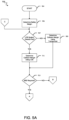
- FIG. 5 A is a flowchart illustrating a process 703 .
- the process 703 begins at the start block 704 .
- the process 703 then proceeds to the block 705 .
- the process 703 determines the safety margin 109 .
- the safety margin 109 may be predetermined, dynamic, or combination thereof. For example, a safety certification may require a predefined and immutable safety margin. On the other hand, a different operating environment may allow for dynamic safety margins (e.g., military applications).
- the process 703 then proceeds to the decision block 707 .
- the process 703 determines whether the line-of-sight system 319 has detected an object ahead of the hyperloop pod 110 A. If the line-of-sight system 319 has not detected an object ahead, the process 703 proceeds to the block 709 .
- the process 703 may determine the collision margin 107 using a transponder. In one aspect, the process 703 may utilize the transponder communication system 321 to communicate with a transponder belonging to a wayside communication network. The process 703 may utilize the functionality of the flight control module 305 to determine current power of the primary traction system 313 and the sensor module 309 to determine velocity.
- the process 703 may determine that the line-of-sight system 319 has detected an object ahead of the hyperloop pod 110 A at which point the process 703 proceeds to the block 711 .
- the process 703 may determine the collision margin 107 using the line-of-sight system 319 .
- the sensor module 309 and the flight control module 305 may be utilized to perform calculations related to determining the collision margin 107 .
- the calculation of the collision margin 107 may be informed by traffic management operations. As described in FIG. 2 above, having various routes may provide for additional distance to increase the collision margin 107 . Such traffic management solutions may operate in concert with maintaining an adequate collision margin. However, safety goals and regulations will likely require more than traffic-based collision avoidance, hence the disclosed solution addressing a long-felt need in the industry.
- the process 703 then proceeds to the decision block 713 .
- the process 703 determines whether the secondary braking system 315 is required to maintain the proper collision margin 107 . The determination may be based on first measuring the current velocity via the sensor module 309 . For example, if the hyperloop pod 110 A is operating at low velocity, then the secondary braking system 315 may be suboptimal at said low velocity, in which case the primary traction system 313 may be more effective and thus utilized. If the secondary braking system 315 is required to maintain the proper collision margin 107 , the process 703 then proceeds along the YES branch to the off-page Reference A, which corresponds to FIG. 5 B . If the secondary braking system 315 is not required in order to maintain the proper collision margin 107 , the process 703 proceeds along the NO branch to the off-page Reference B, which corresponds to FIG. 5 C .
- FIG. 5 B is a flowchart illustrating the process 703 .
- the process 703 resumes from FIG. 5 A at the Reference A.
- the process 703 proceeds to the decision block 731 .
- the process 703 may determine whether the plurality of power electronic units 325 Z are each online.
- the plurality of power electronic units 325 Z may not be all power electronic units disposed on a particular hyperloop pod.
- the plurality of power electronic units 325 Z may be a subset that is managed by the process 703 .
- the process 703 may determine that a particular power electronic unit is online, but the secondary braking system component therein may be offline. In such a situation, the process 703 , at the decision block 731 , may make a similar determination as that when the entire power electronic unit is offline.
- the secondary braking system 315 may be operable to utilize an overdrive mode, in which a particular power electronic unit is run at higher power to induce more magnetic flux, thus generating a stronger eddy current.
- an overdrive mode may be advantageous when fewer than all of the plurality of power electronic units 325 Z are online.
- the power electronic unit 325 E may be offline as well as the secondary braking system component 360 E, housed therein.
- the process 703 may engage the secondary braking system 315 by overdriving the remaining power electronic units in order to meet the desired collision margin (e.g., the collision margin 107 ).
- the process 703 determines that the plurality of power electronic units 325 Z are online, then the process 703 proceeds along the YES branch to the block 733 .
- the process 703 activates the secondary braking system 315 according to a normal operating mode.
- normal operating conditions still may involve an emergency aspect given the need for the secondary braking system 315 being engaged.
- the hyperloop pod 110 A may be experiencing a power failure that requires stopping and requesting assistance, whether or not the hyperloop pod 110 A has in fact engaged the secondary braking system 315 .
- the process 703 may determine that fewer than all the plurality of power electronic units 325 Z are online. The process 703 may then proceed to the block 735 at which point the secondary braking system 315 may be operated using an overdrive mode wherein the remaining power electronic units make up for the loss of one or more power electronic unit. In one aspect, the process 703 may be operable to generate enough braking force using at least two power electronic units that are still online. The process 703 then proceeds to the block 737 .
- the process 703 may determine the thermal load of the secondary braking system 315 .
- the thermal load may be such that damage may occur to the power electronic unit. Further, damage may occur to the track 289 in the event of excess heat being generated by the secondary braking system 315 . If excessive thermal load is detected, the process 703 may, in one aspect, utilize the communication module 311 to relay diagnostic information or emergency information. The process 703 then proceeds to the off-page Reference B.
- FIG. 5 C is a flowchart illustrating the process 703 .
- the process 703 begins at the Reference B and proceeds to the block 751 .
- the process 703 engages the primary traction system 313 in order to reduce velocity.
- the process 703 then proceeds to the decision block 753 .
- the process 703 may determine whether the hyperloop pod 110 A is stopped. In one aspect, the sensor module 309 may be utilized to determine the current velocity. If the hyperloop pod 110 A is not stopped, the process 703 proceeds to the off-page Reference C which corresponds to FIG. 5 A above. If the hyperloop pod is stopped, the process 703 proceeds to the decision block 755 . At the decision block 755 , the process 703 may determine whether an emergency caused the process 703 to engage the secondary braking system 315 . For example, the engagement of the secondary braking system 315 may be due to a minor scheduling error that merely requires correction of pod velocity and position. In contrast, engaging the secondary braking system 315 in order to stop on account of a damaged, downstream pod. If such an emergency is not detected, the process 703 proceeds along the NO branch to the end block 759 and terminates.
- the process 703 proceeds along the YES branch to the block 757 .
- the process 703 may request emergency assistance.
- the process 703 may utilize the communications module 311 (e.g., the wireless communication system 323 ).
- FIG. 6 A is a block diagram illustrating the track 289 having a plurality of transponders 405 N, shown from a side perspective.
- the plurality of transponders 405 N may be comprised of a first transponder 405 A, a second transponder 405 B, a third transponder 405 C, and a fourth transponder 405 D.
- the transponders 405 A, 405 B, 405 C, 405 D may be interconnected via a cable 407 .
- a distance 415 may separate the transponder 405 A from the transponder 405 B.
- a distance may exist between each of the transponders 405 A, 405 B, 405 C, 405 D that is substantially similar to the distance 415 .
- the first hyperloop pod 110 A is maintaining the collision margin 107 greater than the safety margin 109 , i.e., the hyperloop pod 110 A is operating in a relatively safe condition.
- the first hyperloop pod 110 A is operating between the transponder 405 A and the transponder 405 B.
- the second hyperloop pod 110 B is operating between the transponder 405 C and the transponder 405 D.
- the second hyperloop pod 110 B has passed the transponder 405 A as well as the transponder 405 B.
- the hyperloop pod 110 A may gather velocity information relating to the hyperloop pod 110 B.
- the hyperloop pod 110 B may pass the transponder 405 C and relay velocity information to the transponder 405 B via the cable 407 .
- the velocity information may be transmitted from the transponder 405 B to the hyperloop pod 110 A.
- a downstream hyperloop pod may communicate information to an upstream hyperloop pod via the plurality of transponders 405 N.
- other information may be likewise communicated via the plurality of transponders 405 N, including, but not limited to, position, acceleration, weight, energy storage, safety information, passenger information, maintenance information, fare information, etc.
- a line-of-sight detection distance 411 is depicted. However, the line-of-sight detection distance 411 is substantially shorter than the collision margin 107 , as shown in the instant figure.
- the process 700 may utilize the sensor module 309 to determine whether the line-of-sight detection system 319 or the transponder communication system 321 may be utilized.
- the process 703 is likely to rely on the line-of-sight system 319 .
- FIG. 6 B is a block diagram illustrating the track 289 having the plurality of transponders 405 N, shown from a side perspective.
- the line-of-sight detection distance 411 is such that the presence of the hyperloop pod 110 B may be detected using the line-of-sight system 319 .
- the collision margin 107 is shown as being greater than the safety margin 109 . As the collision margin 107 begins to approach the safety margin 109 , the process 703 may engage the primary traction system 313 , the secondary braking system 315 , or combination thereof.
- FIG. 7 is a block diagram illustrating a server 800 suitable for use with the various aspects described herein.
- the server 800 may be operable to execute the process 703 .
- the server 800 may perform the functionality of the processor 302 and the memory 303 described above. Further, the server 800 may execute processes and operations related to the functionality of the automatic pod protection module 301 .
- the server 800 may include one or more processor assemblies 801 (e.g., an x86 processor) coupled to volatile memory 802 (e.g., DRAM) and a large capacity nonvolatile memory 804 (e.g., a magnetic disk drive, a flash disk drive, etc.). As illustrated in instant figure, processor assemblies 801 may be added to the server 800 by inserting them into the racks of the assembly.
- the server 800 may also include an optical drive 806 coupled to the processor 801 .
- the server 800 may also include a network access interface 803 (e.g., an ethernet card, WIFI card, etc.) coupled to the processor assemblies 801 for establishing network interface connections with a network 805 .
- the network 805 may be a local area network, the Internet, the public switched telephone network, and/or a cellular data network (e.g., LTE, 5G, etc.).
- DSP digital signal processor
- ASIC application specific integrated circuit
- FPGA field programmable gate array
- a general-purpose processor may be a microprocessor, a controller, a microcontroller, a state machine, etc.
- a processor may also be implemented as a combination of receiver smart objects, e.g., a combination of a DSP and a microprocessor, a plurality of microprocessors, one or more microprocessors in conjunction with a DSP core, or any other such like configuration. Alternatively, some operations or methods may be performed by circuitry that is specific to a given function.
- the functions described may be implemented in hardware, software, firmware, or any combination thereof. If implemented in software, the functions may be stored as one or more instructions (or code) on a non-transitory computer-readable storage medium or a non-transitory processor-readable storage medium.
- the operations of a method or algorithm disclosed herein may be embodied in a processor-executable software module or as processor-executable instructions, both of which may reside on a non-transitory computer-readable or processor-readable storage medium.
- Non-transitory computer-readable or processor-readable storage media may be any storage media that may be accessed by a computer or a processor (e.g., RAM, flash, etc.).
- non-transitory computer-readable or processor-readable storage media may include RAM, ROM, EEPROM, NAND FLASH, NOR FLASH, M-RAM, P-RAM, R-RAM, CD-ROM, DVD, magnetic disk storage, magnetic storage smart objects, or any other medium that may be used to store program code in the form of instructions or data structures and that may be accessed by a computer.
- Disk as used herein may refer to magnetic or non-magnetic storage operable to store instructions or code.
- Disc refers to any optical disc operable to store instructions or code. Combinations of any of the above are also included within the scope of non-transitory computer-readable and processor-readable media.
- the operations of a method or algorithm may reside as one or any combination or set of codes and/or instructions on a non-transitory processor-readable storage medium and/or computer-readable storage medium, which may be incorporated into a computer program product.
Landscapes
- Engineering & Computer Science (AREA)
- Mechanical Engineering (AREA)
- Physics & Mathematics (AREA)
- Electromagnetism (AREA)
- Transportation (AREA)
- Train Traffic Observation, Control, And Security (AREA)
- Regulating Braking Force (AREA)
Abstract
Description
Claims (20)
Priority Applications (1)
| Application Number | Priority Date | Filing Date | Title |
|---|---|---|---|
| US17/794,959 US12091069B2 (en) | 2020-03-22 | 2021-03-09 | System and method for hyperloop pod protection using braking systems |
Applications Claiming Priority (3)
| Application Number | Priority Date | Filing Date | Title |
|---|---|---|---|
| US202062993044P | 2020-03-22 | 2020-03-22 | |
| PCT/US2021/021579 WO2021194740A1 (en) | 2020-03-22 | 2021-03-09 | System and method for hyperloop pod protection using braking systems |
| US17/794,959 US12091069B2 (en) | 2020-03-22 | 2021-03-09 | System and method for hyperloop pod protection using braking systems |
Publications (2)
| Publication Number | Publication Date |
|---|---|
| US20230347950A1 US20230347950A1 (en) | 2023-11-02 |
| US12091069B2 true US12091069B2 (en) | 2024-09-17 |
Family
ID=75302643
Family Applications (1)
| Application Number | Title | Priority Date | Filing Date |
|---|---|---|---|
| US17/794,959 Active US12091069B2 (en) | 2020-03-22 | 2021-03-09 | System and method for hyperloop pod protection using braking systems |
Country Status (3)
| Country | Link |
|---|---|
| US (1) | US12091069B2 (en) |
| EP (1) | EP4126608B1 (en) |
| WO (1) | WO2021194740A1 (en) |
Cited By (1)
| Publication number | Priority date | Publication date | Assignee | Title |
|---|---|---|---|---|
| US20220324332A1 (en) * | 2021-04-08 | 2022-10-13 | Hyperloop Technologies, Inc. | System and Method for Supervised Autonomous Traffic Management |
Families Citing this family (1)
| Publication number | Priority date | Publication date | Assignee | Title |
|---|---|---|---|---|
| WO2021194740A1 (en) * | 2020-03-22 | 2021-09-30 | Hyperloop Technologies, Inc. | System and method for hyperloop pod protection using braking systems |
Citations (20)
| Publication number | Priority date | Publication date | Assignee | Title |
|---|---|---|---|---|
| JPS5176720A (en) | 1974-10-28 | 1976-07-02 | Mitsubishi Electric Corp | Jikikidosochino bureekisochi |
| US6189980B1 (en) * | 1998-12-18 | 2001-02-20 | Westinghouse Air Brake Company | Locomotive to ECP brake conversion system |
| US20100132584A1 (en) * | 2007-06-01 | 2010-06-03 | Friedrich Loeser | Vehicle having an eddy current brake for a rail-borne transportation system , and a transportation system which is operated therewith, in particular a magnetic levitation train |
| JP5176720B2 (en) * | 2008-06-30 | 2013-04-03 | 株式会社ノーリツ | Equipment control device and cogeneration system |
| US20140288727A1 (en) * | 2013-03-22 | 2014-09-25 | General Motors Llc | Collision sensor, collision sensing system, and method |
| US20160075332A1 (en) * | 2014-09-17 | 2016-03-17 | Magna Electronics Inc. | Vehicle collision avoidance system with enhanced pedestrian avoidance |
| US20160229419A1 (en) * | 2015-02-08 | 2016-08-11 | Hyperloop Technologies, Inc. | Transportation system |
| US20180022405A1 (en) * | 2015-03-31 | 2018-01-25 | Next Future Transportation Inc. | Selectively combinable independent driving vehicles |
| KR20180068818A (en) | 2016-12-14 | 2018-06-22 | 김락영 | SAFE TRAIN BASED ON IoT |
| CN209351405U (en) * | 2018-12-19 | 2019-09-06 | 中铁二院工程集团有限责任公司 | A kind of rack locomotive travel assist system |
| CN110606107A (en) * | 2019-10-10 | 2019-12-24 | 虞萍 | Anti-collision method and device for rail vehicles based on time interval maintenance |
| US20200156605A1 (en) * | 2017-08-22 | 2020-05-21 | Bayerische Motoren Werke Aktiengesellschaft | Emergency Braking System of a Single-Track Vehicle |
| US20200239036A1 (en) * | 2017-08-29 | 2020-07-30 | Krri | Hypertube transport system |
| US20210086739A1 (en) * | 2017-04-11 | 2021-03-25 | Knorr-Bremse Systeme für Schienenfahrzeuge GmbH | Support of train control systems by online transmission of information about braking ability |
| US20210253137A1 (en) * | 2020-02-14 | 2021-08-19 | Safran Landing Systems | Wheeled vehicle station docking using a kneeling landing gear system |
| US20210362758A1 (en) * | 2017-11-14 | 2021-11-25 | Hyperloop Technology Engineering Limited | Retention and loading and unloading in high speed transportation systems |
| US20220194339A1 (en) * | 2019-03-29 | 2022-06-23 | Mando Corporation | Electronic brake system and control method therefor |
| US20230031854A1 (en) * | 2020-01-02 | 2023-02-02 | Crrc Qingdao Sifang Co., Ltd. | Railway vehicle with aerodynamic lift control device |
| US20230161029A1 (en) * | 2021-10-22 | 2023-05-25 | Hyperloop Technologies, Inc. | System and Method for Object Detection in a Hyperloop System |
| US20230347950A1 (en) * | 2020-03-22 | 2023-11-02 | Hyperloop Technologies, Inc. | System and Method for Hyperloop Pod Protection Using Braking Systems |
-
2021
- 2021-03-09 WO PCT/US2021/021579 patent/WO2021194740A1/en not_active Ceased
- 2021-03-09 US US17/794,959 patent/US12091069B2/en active Active
- 2021-03-09 EP EP21715712.2A patent/EP4126608B1/en active Active
Patent Citations (20)
| Publication number | Priority date | Publication date | Assignee | Title |
|---|---|---|---|---|
| JPS5176720A (en) | 1974-10-28 | 1976-07-02 | Mitsubishi Electric Corp | Jikikidosochino bureekisochi |
| US6189980B1 (en) * | 1998-12-18 | 2001-02-20 | Westinghouse Air Brake Company | Locomotive to ECP brake conversion system |
| US20100132584A1 (en) * | 2007-06-01 | 2010-06-03 | Friedrich Loeser | Vehicle having an eddy current brake for a rail-borne transportation system , and a transportation system which is operated therewith, in particular a magnetic levitation train |
| JP5176720B2 (en) * | 2008-06-30 | 2013-04-03 | 株式会社ノーリツ | Equipment control device and cogeneration system |
| US20140288727A1 (en) * | 2013-03-22 | 2014-09-25 | General Motors Llc | Collision sensor, collision sensing system, and method |
| US20160075332A1 (en) * | 2014-09-17 | 2016-03-17 | Magna Electronics Inc. | Vehicle collision avoidance system with enhanced pedestrian avoidance |
| US20160229419A1 (en) * | 2015-02-08 | 2016-08-11 | Hyperloop Technologies, Inc. | Transportation system |
| US20180022405A1 (en) * | 2015-03-31 | 2018-01-25 | Next Future Transportation Inc. | Selectively combinable independent driving vehicles |
| KR20180068818A (en) | 2016-12-14 | 2018-06-22 | 김락영 | SAFE TRAIN BASED ON IoT |
| US20210086739A1 (en) * | 2017-04-11 | 2021-03-25 | Knorr-Bremse Systeme für Schienenfahrzeuge GmbH | Support of train control systems by online transmission of information about braking ability |
| US20200156605A1 (en) * | 2017-08-22 | 2020-05-21 | Bayerische Motoren Werke Aktiengesellschaft | Emergency Braking System of a Single-Track Vehicle |
| US20200239036A1 (en) * | 2017-08-29 | 2020-07-30 | Krri | Hypertube transport system |
| US20210362758A1 (en) * | 2017-11-14 | 2021-11-25 | Hyperloop Technology Engineering Limited | Retention and loading and unloading in high speed transportation systems |
| CN209351405U (en) * | 2018-12-19 | 2019-09-06 | 中铁二院工程集团有限责任公司 | A kind of rack locomotive travel assist system |
| US20220194339A1 (en) * | 2019-03-29 | 2022-06-23 | Mando Corporation | Electronic brake system and control method therefor |
| CN110606107A (en) * | 2019-10-10 | 2019-12-24 | 虞萍 | Anti-collision method and device for rail vehicles based on time interval maintenance |
| US20230031854A1 (en) * | 2020-01-02 | 2023-02-02 | Crrc Qingdao Sifang Co., Ltd. | Railway vehicle with aerodynamic lift control device |
| US20210253137A1 (en) * | 2020-02-14 | 2021-08-19 | Safran Landing Systems | Wheeled vehicle station docking using a kneeling landing gear system |
| US20230347950A1 (en) * | 2020-03-22 | 2023-11-02 | Hyperloop Technologies, Inc. | System and Method for Hyperloop Pod Protection Using Braking Systems |
| US20230161029A1 (en) * | 2021-10-22 | 2023-05-25 | Hyperloop Technologies, Inc. | System and Method for Object Detection in a Hyperloop System |
Non-Patent Citations (3)
| Title |
|---|
| PCT IPEA/409 International Preliminary Report on Patentability Chapter II, PCT/US21/21579, dated Sep. 7, 2021, entire document cited. |
| PCT ISA/210 International Search Report, PCT/US21/21579, dated Jul. 5, 2021, entire document cited. |
| PCT ISA/237 Written Opinion of International Searching Authority, PCT/US21/21579, dated Jul. 5, 2021, entire document cited. |
Cited By (1)
| Publication number | Priority date | Publication date | Assignee | Title |
|---|---|---|---|---|
| US20220324332A1 (en) * | 2021-04-08 | 2022-10-13 | Hyperloop Technologies, Inc. | System and Method for Supervised Autonomous Traffic Management |
Also Published As
| Publication number | Publication date |
|---|---|
| WO2021194740A1 (en) | 2021-09-30 |
| EP4126608A1 (en) | 2023-02-08 |
| US20230347950A1 (en) | 2023-11-02 |
| EP4126608B1 (en) | 2025-09-17 |
Similar Documents
| Publication | Publication Date | Title |
|---|---|---|
| US11630464B2 (en) | Vehicle communication system, control system and method | |
| CN101480962B (en) | Speed controlling method for running of combined train | |
| US8364338B2 (en) | Method, system, and computer software code for wireless remote fault handling on a remote distributed power powered system | |
| CN107709136B (en) | Method and device for determining driving authorization for a rail vehicle | |
| US8655518B2 (en) | Transportation network scheduling system and method | |
| US9235991B2 (en) | Transportation network scheduling system and method | |
| US12091069B2 (en) | System and method for hyperloop pod protection using braking systems | |
| CN111422226B (en) | Block partition setting method and device and storage medium | |
| CN102941865B (en) | System and method for rail train collision prevention based on wireless sensor network | |
| CN105416342A (en) | Apparatus For Warning Of Exceeding Speed Limit In Railway Vehicles | |
| JP2021121149A (en) | Train control device and train control method | |
| KR101355672B1 (en) | Apparatus for Controlling Train and Meathod for the same | |
| JP6399752B2 (en) | Vehicle position recognition device | |
| US20230161029A1 (en) | System and Method for Object Detection in a Hyperloop System | |
| US10065664B1 (en) | System and method for indexing vehicles of a vehicle system | |
| KR102687315B1 (en) | train control system | |
| WO2018207480A1 (en) | Automatic train protection device and on-board device | |
| KR20170033956A (en) | Layered static speed profile calculation method and the device for radio-based train control system | |
| EP3090918B1 (en) | System and method for automatic track element approach | |
| JP2018083495A (en) | Train operation control system | |
| KR101580031B1 (en) | System and method for controlling train | |
| US11198458B2 (en) | Speed control device, wireless train control system, and speed control method | |
| KR101890157B1 (en) | SAFE TRAIN BASED ON IoT | |
| KR101577122B1 (en) | Systems and Method for Stopping Train on Stop Position | |
| JP2013095169A (en) | Ground device, onboard device and vehicle control device |
Legal Events
| Date | Code | Title | Description |
|---|---|---|---|
| FEPP | Fee payment procedure |
Free format text: ENTITY STATUS SET TO UNDISCOUNTED (ORIGINAL EVENT CODE: BIG.); ENTITY STATUS OF PATENT OWNER: LARGE ENTITY |
|
| AS | Assignment |
Owner name: HYPERLOOP TECHNOLOGIES, INC., CALIFORNIA Free format text: ASSIGNMENT OF ASSIGNORS INTEREST;ASSIGNORS:LI, YANNING;WEI, JEROME HUBERT;SIGNING DATES FROM 20220726 TO 20220728;REEL/FRAME:060664/0322 Owner name: HYPERLOOP TECHNOLOGIES, INC., CALIFORNIA Free format text: ASSIGNMENT OF ASSIGNORS INTEREST;ASSIGNORS:LI, YANNING;WEI, JEROME HUBERT;SIGNING DATES FROM 20220726 TO 20220728;REEL/FRAME:060664/0310 |
|
| STPP | Information on status: patent application and granting procedure in general |
Free format text: DOCKETED NEW CASE - READY FOR EXAMINATION |
|
| STPP | Information on status: patent application and granting procedure in general |
Free format text: DOCKETED NEW CASE - READY FOR EXAMINATION |
|
| STPP | Information on status: patent application and granting procedure in general |
Free format text: NOTICE OF ALLOWANCE MAILED -- APPLICATION RECEIVED IN OFFICE OF PUBLICATIONS |
|
| STPP | Information on status: patent application and granting procedure in general |
Free format text: PUBLICATIONS -- ISSUE FEE PAYMENT RECEIVED |
|
| STPP | Information on status: patent application and granting procedure in general |
Free format text: PUBLICATIONS -- ISSUE FEE PAYMENT VERIFIED |
|
| STCF | Information on status: patent grant |
Free format text: PATENTED CASE |
|
| AS | Assignment |
Owner name: DP WORLD LOGISTICS US HOLDINGS, INC., MICHIGAN Free format text: CHANGE OF NAME;ASSIGNOR:HYPERLOOP TECHNOLOGIES, INC.;REEL/FRAME:072757/0363 Effective date: 20250227 |