US1208994A - Dust-bag. - Google Patents
Dust-bag. Download PDFInfo
- Publication number
- US1208994A US1208994A US8239216A US8239216A US1208994A US 1208994 A US1208994 A US 1208994A US 8239216 A US8239216 A US 8239216A US 8239216 A US8239216 A US 8239216A US 1208994 A US1208994 A US 1208994A
- Authority
- US
- United States
- Prior art keywords
- bag
- frame
- section
- hoop
- dust
- Prior art date
- Legal status (The legal status is an assumption and is not a legal conclusion. Google has not performed a legal analysis and makes no representation as to the accuracy of the status listed.)
- Expired - Lifetime
Links
Images

Classifications
-
- B—PERFORMING OPERATIONS; TRANSPORTING
- B01—PHYSICAL OR CHEMICAL PROCESSES OR APPARATUS IN GENERAL
- B01D—SEPARATION
- B01D46/00—Filters or filtering processes specially modified for separating dispersed particles from gases or vapours
- B01D46/02—Particle separators, e.g. dust precipitators, having hollow filters made of flexible material
-
- Y—GENERAL TAGGING OF NEW TECHNOLOGICAL DEVELOPMENTS; GENERAL TAGGING OF CROSS-SECTIONAL TECHNOLOGIES SPANNING OVER SEVERAL SECTIONS OF THE IPC; TECHNICAL SUBJECTS COVERED BY FORMER USPC CROSS-REFERENCE ART COLLECTIONS [XRACs] AND DIGESTS
- Y10—TECHNICAL SUBJECTS COVERED BY FORMER USPC
- Y10S—TECHNICAL SUBJECTS COVERED BY FORMER USPC CROSS-REFERENCE ART COLLECTIONS [XRACs] AND DIGESTS
- Y10S15/00—Brushing, scrubbing, and general cleaning
- Y10S15/08—Dust bags and separators
Definitions
- bags such as are used upon vacuum cleaners, and it is the object of the invention to provide a novel and improved dust collect ing bag for use upon various styles of vacuum cleaners, although the use of the bag is not limited to vacuum cleaners since it can be employed for divers purposes for which it is suited.
- Another object of the invention is the provision of a dust bag having a greater porous or foraminous area, whereby there is less back pressure, with a consequent longer run before the pores are choked up.
- the present bag is provided to overcome the ,ob ections incident to ordinary dust bags.
- an ordinary bag With an ordinary bag, it is a troublesome and dirty job to clean the bag out, it generally being necessary for the hands to come into contact with the dusty inner surface of the bag, to reverse the bag, and to clean the dust from the inner surface thereof.
- an ordinary dust bag becomes choked up comparatively quick, since the pores thereof are filled up with dust in a short time, and this also increases the back pressure, thereby impairing the utility of the vacuum cleaner.
- the present bag eliminates the foregoing and other disadvantages, and is useful upon various styles of vacuum cleaners and similar devices.
- Figure 1 is a longitudinal section of the bag in telescoped form as when in use.
- Fig. 2 is a longitudinal section of the bag in reversed or extended position, as when being cleaned.
- Fig. 3 is a view similar to Fig. 1
- Fig. 4 is a reduced elevation of themodified form in extended position for cleaning.
- Fig. 5 is a cross section on the line 5-5 of Fig. 1.
- Fig. 6 is a longitudinal or diametrical section of another variation, as used in an inclosed type of vacuum cleaner.
- Fig. 7 is an elevation of the third form of bag in extended position for cleaning.
- Fig. 8 is a fragmental elevation of another modification.
- the bag proper is made from any suitable porous fabric or cloth, and is preferably, although not necessarily of circular cross section.
- the bag 1 is relatively long, and tapers from one .end to the other, or decreases in diameter from one end to the other, the larger end ofthe bag being open, and having attached theretoa hoop or ring 2 surrounding the mouth of the bag.
- the smaller end 3 of the bag is provided with a tubular member or sleeve 4, preferably of the same material as the bag, said sleeve and bag being flexible.
- the intermediate portion of the bag 1 has assembled therewith a tubular tapered frame 5, said frame being tapered the same as the bag 1, and being upon the outer' side of the bag, when the bag is in normal operative position.
- This frame 5 can be constructed of wire, wire fabric, or other suitable material, and is preferably provided at its larger end with outstanding fingers 6, which can be used as a means for supporting the bag, although the bag can be supported or mounted upon the vacuum cleaner or other device in any satisfactory manner.
- This frame 5 divides the bag 1 into three sections, viz., the larger section 7 between thehoop 2 and larger end of the frame 5, the intermediate section 8 between the ends of the frame 5, and the smaller section 9 between the smaller end 3 of the bag and the smaller end of the frame 5.
- the larger end of the frame 5 is attached, as at 00, by stitching, hooks and eves, glove fasteners, or the like, to the bag 1 at the juncture of the sections 7 and 8.
- the mouth of the bag is closed by a removable cover 10 composed of a pair of hoops or rings 11 across the inner one of which is stretched a diaphragm '12 of fabric, the same as the bag 1, the margin of said diaphragm being clamped between the hoops 11, although the diaphragm can be attached to a single hoop if preferred.
- the sections thereof are telescoped, as seen in Fig. 1.
- the hoop 2 is at the smaller end of the frame 5, whereby the larger section 7 of the bag surrounds the intermediate section 8, and the smaller "section 9 of the bag is drawn within and surrounded by the frame 5'and intermediate section 8,it being noted that the frame 5 in this position of the bag is upon the outer side thereof, although it is located within one of the folds of the bag.
- the weight of the frame 5 holds the section 7 taut, and said frame also holds the section '8 in upright position withinthe section 7,
- the bag can be supported in any suitable manner, the cover 10 being I normally fitted within the hoop 2 to close the mouth of the bag.
- the pipe P or other conductor which carries the dust laden air from the vacuum cleaner is connected to the bag, by slipping the sleeve 4 onto the pipe P,
- the bag can be made in practically the same size as an ordinary bag, with an increased porous area, and without sacrificing to any appreciable extent, the amount of dust which can be collected within the bag.
- the sections of the bag are concentric, and the air can pass between the sections without difficulty, and it may be said that the walls of the bag are in zig-zagged arrangement when the bag is telescoped.
- the pressure of the air within the bag tends't'o inflate the same, thereby holding the section 9 within the section 8, and the section 7 properly in place around the section 8, it being noted that the section 8 surrounds the frame 5 to be held taut thereby.
- the cover 10 is first removed, and then by grasping the hoop 2 upon the outside thereof, and inverting the bag, the bag will turn inside out of itself, since the frame 5 will drop through the hoop 2, thus pulling the section 8 out of the section 7, also pulling said section 7 through the hoop 2.
- the section 9 will drop out of the frame 5, and the bag will then be in reversed position, with the dusty inner surface thereof upon the outside.
- the dust can then be brushed or otherwise removed from the inner surface of the bag, the bag being suspended by the hoop 2, it not being necessary to touch the dusty surface of the bag, either during the cleaning of the bag or the unfolding or folding thereof.
- the operator can insert one arm into the bag to catch hold of the frame 5, and the hoop 2 is then passed over the frame 5 which brings the section 7 back into place around the sect-ion 8, and then by catching hold of the sleeve 4 within the section 9, said section 9 can be pulled into place within the frame 5, and at no time is it necessary to touch the inner surface of the bag.
- the cover 10 after being cleaned, is again inserted within the hoop 2 to close the mouth of the bag, and the bag is ready for use. The bag can be cleaned out quickly and with little trouble.
- Some dust bags use two thicknesses of material, or one bag within another, the inner one being of coarse fabric or material, while the outer one is of fine mesh. This reduces the choking of the fine pores, since the inner sheet or bag will catch the coarser particles, while the outer bag or sheet need only arrest the smaller particles.
- This principle can be used with the present bag, as depicted in Figs. 3 and 4.
- the parts 1 to 12, inclusive, of this modified form are the same as above described so that the bag in its essential features is the same as the first form, with an additional bag 1 assembled therewith.
- the main bag 1 is of fine material and is the outer one, while the bag 1 is of coarse material and is normally within the outer bag 1.
- the two bags are of tapered form, and have their smaller ends 33 attached together, as seen in Fig.
- the bag 1 has a hoop 2 attached to its larger end. en thestructure is telescoped, the hoop 2 fits within the hoop 2, and the sections 7, 8 and 9 of the bag 1 are disposed adjacent to and extend along the inner surfaces of the sections 7, 8 and 9, respectively, of the outer bag 1.
- the cover 10 fits within the hoop 2 in this case, and the cover 10 is preferably provided with an additional hoop 11 securing in place an inner diaphragm. 12 of porous material, while the diaphragm 12 is smaller end of the bag 1 of fine material.
- the inner bag will arrest the larger particles, while the fine particles will be caught by the outer bag.
- the cover 10 is first removed, and then by holding the hoop 2--2 and inverting the device, the two bags will be turned inside out simultaneously. Then, by removing the hoop 2 from the hoop 2", and moving said hoops apart, the bags 1 and 1 are separated, as seen in Fig. 4, thus exposing the dust surfaces of the two bags whereby they can be cleaned conveniently.
- the device can be restored to normal position, by first returning the bags one over the other, and fitting the hoops. 22 together, after which the bags are teleseoped the same as with a single bag.
- a bag 1 adapted especially for use in an inclosed type of vacuum cleaner.
- This bag 1 is tapered from one end to the other, and has attached to its larger end, the hoop 2 the being closed, as at 3
- the bag in this case is composed of five or more instead of three sections.
- a five section bag is shown and described and its sections are designated 7, 8 7 8 and 9
- Assembled with the sections 8 and 8 are the respective annular tapered frames 5 and 5 the frame 5 being of smaller size than the frame 5 and being normally disposed therein when the bag is folded.
- the larger ends of the frames are attached, as at w, to the bag 1
- the section 7 is suspended from the hoop 2 with the frame 5 supported by the lower end of the section 7 and projecting upwardly therein to hold the section 8 in place and the section '2' is suspended from the upper end of the frame 5 within said frame.
- Theframe 5 is suspended by the section 7 and projects upwardly therein to hold the section 8 in place, and the section 9 is suspended from the upper end of the frame 5 within said frame.
- the sections of the bag are supported by one another, with the sections concentric and their walls in zig-zagged arrangement.
- This bag is adapted for use within the upper portion of an upright vacuum cleaner casing 13, as seen in F ig; 6, although this type of bag can be used as a diaphragm type bag for other purposes.
- the bag l is suspended within the casing 13 above a screen partition or diaphragm 14 -within the casing 13, which may be used to assist 1n supporting the bag if desired, the
- hoop 2 being seated upon a seat 15 with which the upper end or mouth of the casing 13 is provided.
- the ring 2 is clamped upon the seat 15 by the cover 16, which is provided with an air suction opening llflto which the air hose or conductor is connected, so that the dust laden air is drawn into the upper end of the casing 13 above the bag.
- he casing 13 is provided therein with a diaphragm 18 or other device for creating bag, so that the air must flow through the I varlous sections of the bag which will arrest the dust and other particles.
- the telescoped form of the bag materially increases the area of the fabric, for the purposes above noted, and the bag can be readily removed and cleaned when the cover 16 is moved out of the way.
- the frames 5 and 5 will drop through the hoop 2 to thus extend the bag and turn it in-- side out.
- the latter type of bag can also be made in double form, the same as the bag illustrated in Figs. 3 and l, with a hoop at the large .end of each bag, and with the small ends fastened together at their centers, as shown in Fig. 8.
- This form will have all the advantages of the external type of double bag above described, and can be reversed for cleaning in practically the same manner.
- a dust collecting bag having outer, intermediate and inner portions, and a frame upstanding Within and supported from the lower end of the outer portion of the bag, to hold the intermediate portion in place, the inner portion of the bag being suspended from the upper end of said frame.
- a tapered dust collecting bag having an outer portion adjacent its larger end, an intermediate-portion within the outer portion, and an inner portion adjacent its smaller end within the intermediate portion, and a tapered frame having its larger end attached to the bag'adjacent the smaller end of the outer portion, whereby said frame is supported in upstanding position within the outer portion of the bag from the lower end thereof, said frame supporting the intermediate portion of the bag, and the inner portion of the bag being suspended from the upper smaller end of said frame.
- a dust collecting bag tapered from one end to another and having an outer portion adjacent its larger end, an intermediate portion within the outer portion, and an inner portion Within the intermediate portion, a
- a tapered dust collecting bag adapted to be folded between its ends so that the smaller portion of the bag comes within the larger portion in telescopic arrangement, a
- hoop attached to the larger end of the bag, and-a closure for the larger end of the bag having a hoop to fit the aforesaid hoop, and a porous diaphragm.
- a dust collecting device embodying a pair of tapered bags having'their smaller ends attached together, one bag being movable over the other, the larger ends of the bags being separable, and the two bags,
- a dust collecting device embodying a pair of tapered bags constructed of porous material of different mesh, the smaller ends of the bags being attached together, hoops attached to the larger ends of the bags and adapted to fit one another when one bag is moved over the other, said hoops being separable to separate the bags, the bags, when one bag is moved over the other and the hoops fitted together, being foldable into telescopic position.
Landscapes
- Chemical & Material Sciences (AREA)
- Chemical Kinetics & Catalysis (AREA)
- Filters For Electric Vacuum Cleaners (AREA)
Description
1. C. LION.
DUST BAG.
APPLICATION FILED MAR. s. 1916.
/ Witnesses Patented Dec. 19, 1916.
2 SHEETS-SHEET I.
Attorneys J. C. LION.
DUST BAG.
APPLICATION FILED'MAR. s. 1916.
Patented Dec. 19, 1916.
2 SHEETS-SHEET 2- (i (f ff Inventor Attorneys rra sr s Bron.
JOHN CHARLES LION, OF ST. MARYS, PENNSYLVANIA.
DUST-BAG.
Specification of Letters Patent. Patented Dec, 19, 1916,
Application filed March 6, 1916. Serial No. 82,392.
bags, such as are used upon vacuum cleaners, and it is the object of the invention to provide a novel and improved dust collect ing bag for use upon various styles of vacuum cleaners, although the use of the bag is not limited to vacuum cleaners since it can be employed for divers purposes for which it is suited.
It is the object of the invention to provide a dust bag of comparatively simple and inexpensive construction, which can be readily cleaned, thebag being quickly and conveniently turned inside out or reversed without the necessity of the hands touching the inner surface of the bag.
Another object of the invention is the provision of a dust bag having a greater porous or foraminous area, whereby there is less back pressure, with a consequent longer run before the pores are choked up.
The present bag is provided to overcome the ,ob ections incident to ordinary dust bags. With an ordinary bag, it is a troublesome and dirty job to clean the bag out, it generally being necessary for the hands to come into contact with the dusty inner surface of the bag, to reverse the bag, and to clean the dust from the inner surface thereof. Furthermore, an ordinary dust bag becomes choked up comparatively quick, since the pores thereof are filled up with dust in a short time, and this also increases the back pressure, thereby impairing the utility of the vacuum cleaner. The present bag eliminates the foregoing and other disadvantages, and is useful upon various styles of vacuum cleaners and similar devices.
71th the foregoing and other objects in view which will appear as the description proceeds, the invention resides in the com bination and arrangement of parts and in the details of construction hereinafter described and claimed, it being understood that changes in the precise embodiment of the invention herein disclosed can be made within the scope of what is claimed without departing from the spiritfof the invention.
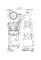
The invention is illustrated in the accompanying drawings, wherein Figure 1 is a longitudinal section of the bag in telescoped form as when in use. Fig. 2 is a longitudinal section of the bag in reversed or extended position, as when being cleaned. Fig. 3"is a view similar to Fig. 1
of a modification. Fig. 4 is a reduced elevation of themodified form in extended position for cleaning. Fig. 5 is a cross section on the line 5-5 of Fig. 1. Fig. 6 is a longitudinal or diametrical section of another variation, as used in an inclosed type of vacuum cleaner. Fig. 7 is an elevation of the third form of bag in extended position for cleaning. Fig. 8 is a fragmental elevation of another modification.
Referring specifically to Figs. 1, 2 and 3, wherein one form of the invention is depicted, there is designated by the numeral 1, the bag proper. This bag 1 is made from any suitable porous fabric or cloth, and is preferably, although not necessarily of circular cross section. The bag 1 is relatively long, and tapers from one .end to the other, or decreases in diameter from one end to the other, the larger end ofthe bag being open, and having attached theretoa hoop or ring 2 surrounding the mouth of the bag. The
fabric can be glued, sewed or otherwise attached to the hoop 2 as is found most satis-. factory. The smaller end 3 of the bag is provided with a tubular member or sleeve 4, preferably of the same material as the bag, said sleeve and bag being flexible.
The intermediate portion of the bag 1 has assembled therewith a tubular tapered frame 5, said frame being tapered the same as the bag 1, and being upon the outer' side of the bag, when the bag is in normal operative position. This frame 5 can be constructed of wire, wire fabric, or other suitable material, and is preferably provided at its larger end with outstanding fingers 6, which can be used as a means for supporting the bag, although the bag can be supported or mounted upon the vacuum cleaner or other device in any satisfactory manner. This frame 5 divides the bag 1 into three sections, viz., the larger section 7 between thehoop 2 and larger end of the frame 5, the intermediate section 8 between the ends of the frame 5, and the smaller section 9 between the smaller end 3 of the bag and the smaller end of the frame 5. The larger end of the frame 5 is attached, as at 00, by stitching, hooks and eves, glove fasteners, or the like, to the bag 1 at the juncture of the sections 7 and 8.
The mouth of the bag is closed by a removable cover 10 composed of a pair of hoops or rings 11 across the inner one of which is stretched a diaphragm '12 of fabric, the same as the bag 1, the margin of said diaphragm being clamped between the hoops 11, although the diaphragm can be attached to a single hoop if preferred.
When the bag is in operativeposition, the sections thereof are telescoped, as seen in Fig. 1. The hoop 2 is at the smaller end of the frame 5, whereby the larger section 7 of the bag surrounds the intermediate section 8, and the smaller "section 9 of the bag is drawn within and surrounded by the frame 5'and intermediate section 8,it being noted that the frame 5 in this position of the bag is upon the outer side thereof, although it is located within one of the folds of the bag.
,When the bag is suspended by the hoop 2,
the weight of the frame 5 holds the section 7 taut, and said frame also holds the section '8 in upright position withinthe section 7,
while the section 9 is suspended from the upper end of the frame 5 thereby holding the various parts of the bag in proper posi-. tion. The bag, however, can be supported in any suitable manner, the cover 10 being I normally fitted within the hoop 2 to close the mouth of the bag. The pipe P or other conductor which carries the dust laden air from the vacuum cleaner is connected to the bag, by slipping the sleeve 4 onto the pipe P,
whereby the air is delivered into the bag by waycof the sleeve 4. Particular attention is directed to the fact that the air can escape through all of the sections 7, 8 and 9 of the bag; the end 8 thereof, and the cover 10, thereby providing a comparatively large porous area for the escape of the air, which area is much larger than the corresponding area of an ordinary dust bag. This reduces the back pressure,since the air can escape more freely, and furthermore, the present bag will take a much longer time to choke it up with dust, since there is a greater area to be covered with dust before the choking takes place. a
The bag can be made in practically the same size as an ordinary bag, with an increased porous area, and without sacrificing to any appreciable extent, the amount of dust which can be collected within the bag. The sections of the bag are concentric, and the air can pass between the sections without difficulty, and it may be said that the walls of the bag are in zig-zagged arrangement when the bag is telescoped. The pressure of the air within the bag tends't'o inflate the same, thereby holding the section 9 within the section 8, and the section 7 properly in place around the section 8, it being noted that the section 8 surrounds the frame 5 to be held taut thereby.
To clean out the bag, the cover 10 is first removed, and then by grasping the hoop 2 upon the outside thereof, and inverting the bag, the bag will turn inside out of itself, since the frame 5 will drop through the hoop 2, thus pulling the section 8 out of the section 7, also pulling said section 7 through the hoop 2. The section 9 will drop out of the frame 5, and the bag will then be in reversed position, with the dusty inner surface thereof upon the outside. The dust can then be brushed or otherwise removed from the inner surface of the bag, the bag being suspended by the hoop 2, it not being necessary to touch the dusty surface of the bag, either during the cleaning of the bag or the unfolding or folding thereof. To fold the bag, the operator can insert one arm into the bag to catch hold of the frame 5, and the hoop 2 is then passed over the frame 5 which brings the section 7 back into place around the sect-ion 8, and then by catching hold of the sleeve 4 within the section 9, said section 9 can be pulled into place within the frame 5, and at no time is it necessary to touch the inner surface of the bag. The cover 10 after being cleaned, is again inserted within the hoop 2 to close the mouth of the bag, and the bag is ready for use. The bag can be cleaned out quickly and with little trouble. L
Some dust bags use two thicknesses of material, or one bag within another, the inner one being of coarse fabric or material, while the outer one is of fine mesh. This reduces the choking of the fine pores, since the inner sheet or bag will catch the coarser particles, while the outer bag or sheet need only arrest the smaller particles. This principle can be used with the present bag, as depicted in Figs. 3 and 4. The parts 1 to 12, inclusive, of this modified form are the same as above described so that the bag in its essential features is the same as the first form, with an additional bag 1 assembled therewith. The main bag 1 is of fine material and is the outer one, while the bag 1 is of coarse material and is normally within the outer bag 1. The two bags are of tapered form, and have their smaller ends 33 attached together, as seen in Fig. 4, and the bag 1 has a hoop 2 attached to its larger end. en thestructure is telescoped, the hoop 2 fits within the hoop 2, and the sections 7, 8 and 9 of the bag 1 are disposed adjacent to and extend along the inner surfaces of the sections 7, 8 and 9, respectively, of the outer bag 1. The cover 10 fits within the hoop 2 in this case, and the cover 10 is preferably provided with an additional hoop 11 securing in place an inner diaphragm. 12 of porous material, while the diaphragm 12 is smaller end of the bag 1 of fine material. Thus, the inner bag will arrest the larger particles, while the fine particles will be caught by the outer bag. To clean the device, the cover 10 is first removed, and then by holding the hoop 2--2 and inverting the device, the two bags will be turned inside out simultaneously. Then, by removing the hoop 2 from the hoop 2", and moving said hoops apart, the bags 1 and 1 are separated, as seen in Fig. 4, thus exposing the dust surfaces of the two bags whereby they can be cleaned conveniently. The device can be restored to normal position, by first returning the bags one over the other, and fitting the hoops. 22 together, after which the bags are teleseoped the same as with a single bag.
In Figs. 6 and 7 there is illustrated a bag 1 adapted especially for use in an inclosed type of vacuum cleaner. This bag 1 is tapered from one end to the other, and has attached to its larger end, the hoop 2 the being closed, as at 3 The bag in this case is composed of five or more instead of three sections. A five section bag is shown and described and its sections are designated 7, 8 7 8 and 9 Assembled with the sections 8 and 8 are the respective annular tapered frames 5 and 5 the frame 5 being of smaller size than the frame 5 and being normally disposed therein when the bag is folded. The larger ends of the frames are attached, as at w, to the bag 1 When the bag is folded, the section 7 is suspended from the hoop 2 with the frame 5 supported by the lower end of the section 7 and projecting upwardly therein to hold the section 8 in place and the section '2' is suspended from the upper end of the frame 5 within said frame. Theframe 5 is suspended by the section 7 and projects upwardly therein to hold the section 8 in place, and the section 9 is suspended from the upper end of the frame 5 within said frame. Thus, the sections of the bag are supported by one another, with the sections concentric and their walls in zig-zagged arrangement. This bag is adapted for use within the upper portion of an upright vacuum cleaner casing 13, as seen in F ig; 6, although this type of bag can be used as a diaphragm type bag for other purposes. The bag l is suspended within the casing 13 above a screen partition or diaphragm 14 -within the casing 13, which may be used to assist 1n supporting the bag if desired, the
The latter type of bag can also be made in double form, the same as the bag illustrated in Figs. 3 and l, with a hoop at the large .end of each bag, and with the small ends fastened together at their centers, as shown in Fig. 8. This form will have all the advantages of the external type of double bag above described, and can be reversed for cleaning in practically the same manner.
Having thus described the invention, what is claimed as new is:
1. A dust collecting bag having outer, intermediate and inner portions, and a frame upstanding Within and supported from the lower end of the outer portion of the bag, to hold the intermediate portion in place, the inner portion of the bag being suspended from the upper end of said frame.
2. A tapered dust collecting bag having an outer portion adjacent its larger end, an intermediate-portion within the outer portion, and an inner portion adjacent its smaller end within the intermediate portion, and a tapered frame having its larger end attached to the bag'adjacent the smaller end of the outer portion, whereby said frame is supported in upstanding position within the outer portion of the bag from the lower end thereof, said frame supporting the intermediate portion of the bag, and the inner portion of the bag being suspended from the upper smaller end of said frame.
3. A dust collecting bag tapered from one end to another and having an outer portion adjacent its larger end, an intermediate portion within the outer portion, and an inner portion Within the intermediate portion, a
hoop attached to the larger end of the bag for suspending the outer portion thereof, and a tapered frame having its larger end attached to the bag adjacent the lower end of the outer portion thereof, said frame being supported in upstanding position within the outer portion of the bag with its smaller end uppermost, the intermediate portion of the bag surrounding said frame, and the inner portion of the bag being suspended from the upper smaller end of said frame. I
4.. A tapered dust collecting bag adapted to be folded between its ends so that the smaller portion of the bag comes within the larger portion in telescopic arrangement, a
hoop attached to the larger end of the bag, and-a closure for the larger end of the bag having a hoop to fit the aforesaid hoop, and a porous diaphragm.
5. A dust collecting device embodying a pair of tapered bags having'their smaller ends attached together, one bag being movable over the other, the larger ends of the bags being separable, and the two bags,
when one is moved over the other, being foldable into telescopic position.
6. A dust collecting device embodying a pair of tapered bags constructed of porous material of different mesh, the smaller ends of the bags being attached together, hoops attached to the larger ends of the bags and adapted to fit one another when one bag is moved over the other, said hoops being separable to separate the bags, the bags, when one bag is moved over the other and the hoops fitted together, being foldable into telescopic position.
In testimony that I claim the foregoing as my own, I have hereto aflixed my signature in the presence of two witnesses.
JOHN CHARLES LION.
Witnesses:
J. G. B/UNLEN, J. A. MiiLLHaUrT.
Priority Applications (1)
| Application Number | Priority Date | Filing Date | Title |
|---|---|---|---|
| US8239216A US1208994A (en) | 1916-03-06 | 1916-03-06 | Dust-bag. |
Applications Claiming Priority (1)
| Application Number | Priority Date | Filing Date | Title |
|---|---|---|---|
| US8239216A US1208994A (en) | 1916-03-06 | 1916-03-06 | Dust-bag. |
Publications (1)
| Publication Number | Publication Date |
|---|---|
| US1208994A true US1208994A (en) | 1916-12-19 |
Family
ID=3276898
Family Applications (1)
| Application Number | Title | Priority Date | Filing Date |
|---|---|---|---|
| US8239216A Expired - Lifetime US1208994A (en) | 1916-03-06 | 1916-03-06 | Dust-bag. |
Country Status (1)
| Country | Link |
|---|---|
| US (1) | US1208994A (en) |
Cited By (4)
| Publication number | Priority date | Publication date | Assignee | Title |
|---|---|---|---|---|
| US2533268A (en) * | 1947-07-24 | 1950-12-12 | Breuer Electric Mfg Company | Combined blower and vacuum cleaner |
| DE884904C (en) * | 1940-11-09 | 1953-07-30 | Bayer Ag | filter |
| US3890290A (en) * | 1974-02-21 | 1975-06-17 | Esm Inc | Apparatus for filtering particulate matter from a fluid stream |
| US4405346A (en) * | 1981-05-13 | 1983-09-20 | The Hoover Company | Cleaner with dirt cup |
-
1916
- 1916-03-06 US US8239216A patent/US1208994A/en not_active Expired - Lifetime
Cited By (4)
| Publication number | Priority date | Publication date | Assignee | Title |
|---|---|---|---|---|
| DE884904C (en) * | 1940-11-09 | 1953-07-30 | Bayer Ag | filter |
| US2533268A (en) * | 1947-07-24 | 1950-12-12 | Breuer Electric Mfg Company | Combined blower and vacuum cleaner |
| US3890290A (en) * | 1974-02-21 | 1975-06-17 | Esm Inc | Apparatus for filtering particulate matter from a fluid stream |
| US4405346A (en) * | 1981-05-13 | 1983-09-20 | The Hoover Company | Cleaner with dirt cup |
Similar Documents
| Publication | Publication Date | Title |
|---|---|---|
| US2876481A (en) | Suction cleaners | |
| US2460851A (en) | Bag coupling for suction cleaners | |
| US2283835A (en) | Inlet valve for suction cleaner dirt bags | |
| US2467503A (en) | Dust container for vacuum cleaners | |
| US3457707A (en) | Vacuum cleaner filter bag | |
| US2951553A (en) | Vacuum cleaner | |
| US1208994A (en) | Dust-bag. | |
| US4084948A (en) | Vacuum cleaner filter bag assembly | |
| USRE17852E (en) | willis | |
| US1422105A (en) | Suction cleaner | |
| US3971643A (en) | Vacuum cleaner including dust bag and filter | |
| US1929025A (en) | Bagless vacuum cleaner | |
| US1504136A (en) | Sanitary dust bag | |
| US2286421A (en) | Suction cleaner | |
| US2418371A (en) | Suction cleaner | |
| US1859861A (en) | Dust separator | |
| US1655875A (en) | Suction cleaner | |
| US2637409A (en) | Disposable dust bag for vacuum cleaners | |
| US1989868A (en) | Vacuum cleaner | |
| US2514280A (en) | Suction cleaner | |
| US1403112A (en) | Dustproof vacuum-cleaner bag | |
| US3387433A (en) | Dust collector | |
| US3350857A (en) | Vacuum cleaner filter bag | |
| US2327225A (en) | Suction cleaning apparatus | |
| US2016294A (en) | Air-method cleaner |