US12089673B2 - Methods and apparatus for a sound reducing mask - Google Patents
Methods and apparatus for a sound reducing mask Download PDFInfo
- Publication number
- US12089673B2 US12089673B2 US17/865,561 US202217865561A US12089673B2 US 12089673 B2 US12089673 B2 US 12089673B2 US 202217865561 A US202217865561 A US 202217865561A US 12089673 B2 US12089673 B2 US 12089673B2
- Authority
- US
- United States
- Prior art keywords
- mask
- user
- body portion
- muffler
- sound
- Prior art date
- Legal status (The legal status is an assumption and is not a legal conclusion. Google has not performed a legal analysis and makes no representation as to the accuracy of the status listed.)
- Active, expires
Links
- 238000000034 method Methods 0.000 title claims abstract description 18
- 239000011358 absorbing material Substances 0.000 claims description 12
- 229920000742 Cotton Polymers 0.000 claims description 5
- 229920005830 Polyurethane Foam Polymers 0.000 claims description 3
- 229920001296 polysiloxane Polymers 0.000 claims description 3
- 239000011496 polyurethane foam Substances 0.000 claims description 3
- 125000000391 vinyl group Chemical group [H]C([*])=C([H])[H] 0.000 claims description 3
- 229920002554 vinyl polymer Polymers 0.000 claims description 3
- 230000008901 benefit Effects 0.000 description 7
- 239000000463 material Substances 0.000 description 6
- 238000012986 modification Methods 0.000 description 6
- 230000004048 modification Effects 0.000 description 6
- 210000005069 ears Anatomy 0.000 description 4
- 239000004744 fabric Substances 0.000 description 4
- 239000011148 porous material Substances 0.000 description 4
- 239000004677 Nylon Substances 0.000 description 2
- 238000004519 manufacturing process Methods 0.000 description 2
- 239000000203 mixture Substances 0.000 description 2
- 229920001778 nylon Polymers 0.000 description 2
- 229920000728 polyester Polymers 0.000 description 2
- 230000001755 vocal effect Effects 0.000 description 2
- 210000002268 wool Anatomy 0.000 description 2
- 206010013975 Dyspnoeas Diseases 0.000 description 1
- 229920001410 Microfiber Polymers 0.000 description 1
- 229920002334 Spandex Polymers 0.000 description 1
- 230000000712 assembly Effects 0.000 description 1
- 238000000429 assembly Methods 0.000 description 1
- 238000010586 diagram Methods 0.000 description 1
- 229920001971 elastomer Polymers 0.000 description 1
- 239000003658 microfiber Substances 0.000 description 1
- 230000002093 peripheral effect Effects 0.000 description 1
- 230000002035 prolonged effect Effects 0.000 description 1
- 230000029058 respiratory gaseous exchange Effects 0.000 description 1
- -1 silk Polymers 0.000 description 1
Images


Classifications
-
- A—HUMAN NECESSITIES
- A41—WEARING APPAREL
- A41D—OUTERWEAR; PROTECTIVE GARMENTS; ACCESSORIES
- A41D13/00—Professional, industrial or sporting protective garments, e.g. surgeons' gowns or garments protecting against blows or punches
- A41D13/05—Professional, industrial or sporting protective garments, e.g. surgeons' gowns or garments protecting against blows or punches protecting only a particular body part
- A41D13/11—Protective face masks, e.g. for surgical use, or for use in foul atmospheres
-
- A—HUMAN NECESSITIES
- A41—WEARING APPAREL
- A41D—OUTERWEAR; PROTECTIVE GARMENTS; ACCESSORIES
- A41D31/00—Materials specially adapted for outerwear
- A41D31/04—Materials specially adapted for outerwear characterised by special function or use
-
- A—HUMAN NECESSITIES
- A41—WEARING APPAREL
- A41D—OUTERWEAR; PROTECTIVE GARMENTS; ACCESSORIES
- A41D13/00—Professional, industrial or sporting protective garments, e.g. surgeons' gowns or garments protecting against blows or punches
- A41D13/05—Professional, industrial or sporting protective garments, e.g. surgeons' gowns or garments protecting against blows or punches protecting only a particular body part
- A41D13/11—Protective face masks, e.g. for surgical use, or for use in foul atmospheres
- A41D13/1161—Means for fastening to the user's head
-
- G—PHYSICS
- G10—MUSICAL INSTRUMENTS; ACOUSTICS
- G10K—SOUND-PRODUCING DEVICES; METHODS OR DEVICES FOR PROTECTING AGAINST, OR FOR DAMPING, NOISE OR OTHER ACOUSTIC WAVES IN GENERAL; ACOUSTICS NOT OTHERWISE PROVIDED FOR
- G10K11/00—Methods or devices for transmitting, conducting or directing sound in general; Methods or devices for protecting against, or for damping, noise or other acoustic waves in general
- G10K11/16—Methods or devices for protecting against, or for damping, noise or other acoustic waves in general
- G10K11/162—Selection of materials
Definitions
- a person may behave in a manner that may disturb and/or irritate others. For example, a person, such as a child, may shout and cry when upset. Accordingly, nearby persons may be disturbed and/or irritated, especially in a crowded shared-space environment. In cases such as this, a mask may be placed over the person's mouth to reduce the sound generated by the person.
- a conventional sound reducing mask generally covers the person's mouth and nose and contains two orifices to allow the person to breathe through his or her nose.
- the orifices are generally small and therefore restrict airflow to the mask. Accordingly, a conventional sound reducing mask may cause the person wearing the mask to have difficulty breathing.
- a conventional sound reducing mask may be made of rubber, making the mask heavy and uncomfortable to wear.
- Methods and apparatus for a sound reducing mask wearable by a user may comprise a body portion contoured to form a seal with the user's face when the body portion is placed over the user's mouth.
- the sound reducing mask may also comprise an air intake assembly comprising an inlet and a unidirectional flap configured to move between an open position and a closed position.
- Methods and apparatus for a sound reducing mask may further comprise a muffler configured to muffle noise made by the user.
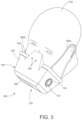
- FIG. 1 representatively illustrates a front perspective view of a sound reducing mask in accordance with an embodiment of the subject technology
- FIG. 2 representatively illustrates a rear perspective view of the sound reducing mask illustrated in FIG. 1 ;
- FIG. 3 representatively illustrates a sound reducing mask positioned for use in accordance with an embodiment of the subject technology
- FIG. 4 representatively illustrates a flow diagram for operating a sound reducing mask in accordance with an embodiment of the subject technology.
- the subject technology may be described in terms of functional components. Such functional components may be realized by any number of components configured to perform the specified functions and achieve the various results.
- the subject technology may employ various air intake assemblies, flaps, inlets, sound-absorbing materials, mufflers, ear straps, headgear, headstraps, headbands, and the like, which may carry out a variety of functions.
- the subject technology may be practiced in conjunction with any one of various sound reducing systems, and the sound reducing mask described herein is merely one exemplary application for the technology.
- an exemplary sound reducing mask 100 may be worn by a user 102 , such as a child or baby.
- the sound reducing mask 100 may be placed over at least the mouth of the user 102 so that the user 102 may shout and/or cry in an environment without disturbing nearby persons.
- an “environment” is any type of shared-space environment, such as an aircraft cabin, a train cabin, a library, and the like.
- the user 102 does not necessarily have to be a child or baby.
- the sound reducing mask 100 may comprise a body portion 105 , an air intake assembly 110 , and a muffler 115 .
- the body portion 105 may be contoured to form a seal with the face of the user 102 when the body portion 105 is placed over the mouth of the user 102 .
- the body portion 105 may comprise an exterior surface 120 and an interior surface 125 .
- the body portion 105 may also comprise an open proximal end 130 and a distal end 135 opposite the proximal end 130 .
- the open proximal end 130 may terminate in a peripheral brim 140 that forms an effective seal with the face of the user 102 when the body portion 105 is placed over the mouth of the user 102 .
- the interior surface 125 of the body portion 105 may define a receptacle cavity 145 for receiving the mouth of the user 102 .
- the body portion 105 may further comprise one or more orifices 150 to allow the user 102 to breathe through his or her nose.
- Each orifice 150 may comprise any suitable diameter.
- each orifice 150 may comprise a diameter between about 0.05 inches and about 0.1 inches.
- the body portion 105 may comprise a sound-absorbing layer 155 for absorbing sound emitted by the user 102 .
- the sound-absorbing layer 155 may be constructed from any suitable sound-absorbing material, such as silicone, polyurethane foam, vinyl, cotton, mat, or felt, or a combination thereof.
- the sound-absorbing layer 155 may be capable of absorbing between about 20 decibels and about 30 decibels of noise.
- the sound-absorbing material may be selected according to its particular application. For instance, the sound-absorbing material may be selected according to its acoustic impedance value.
- the porous material may absorb high-frequency (i.e., small wavelength) sound waves more effectively than low-frequency (i.e., large wavelength) sound waves.
- the porous material may absorb low-frequency (i.e., large wavelength) sound waves more effectively than high-frequency (i.e., small wavelength) sound waves.
- high-frequency sound waves are sound waves with frequencies greater than or equal to 500 Hz
- low-frequency sound waves are sound waves with frequencies below 500 Hz.
- the body portion 105 may comprise at least one of an ear strap, headgear, headstrap, or headband for securely attaching the sound reducing mask 100 to the face of the user 102 .
- the body portion 105 may comprise a first strap 160 a and a second strap 160 b .
- Each strap 160 a , 160 b may be adjustable to provide a more comfortable or customizable fit around and/or over the ears of the user 102 .
- the first and second straps 160 a , 160 b may be made of a comfortable material or fabric intended to be in prolonged contact with the ears of the user 102 , such as polyester, nylon, silk, cotton, wool, linen, and the like.
- first and second straps 160 a , 160 b may instead comprise a single pliable strip of material that provides enough stretch or elasticity to fit a variety of head sizes.
- the pliable strip may comprise a stretchy material and may be sewn into or otherwise attached to a portion of the sound reducing mask 100 that will be in contact with the ears and/or head of the user 102 during use.
- the stretchy material may comprise any suitable material or fabric such as: elastic fabric, elastane, microfibers, nylon, polyester, stretchy mesh fabric, cotton, wool, or any combination thereof.
- the air intake assembly 110 may be positioned at the distal end 135 opposite the mouth of the user 102 .
- the air intake assembly 110 may comprise a unidirectional flap 165 and an air inlet 170 .
- the unidirectional flap 165 may be configured to move, relative to the body portion 105 , between an open position, as shown in FIG. 1 , and a closed position, as shown in FIG. 3 .
- the unidirectional flap 165 may move between the open position and the closed position according to the internal pressure of the receptacle cavity 145 .
- the default position of the unidirectional flap 165 may be the closed position, but the unidirectional flap 165 may move to the open position when a negative pressure is induced inside the receptacle cavity 145 .
- a negative pressure may be induced inside the receptacle cavity 145 when the user 102 inhales. Accordingly, air may be drawn into the mask 100 via the inlet 170 when the unidirectional flap 165 is in the open position. The unidirectional flap 165 may return to the closed position when a positive pressure is induced inside the receptacle cavity 145 . A positive pressure may be induced inside the receptacle cavity 145 after the air is drawn into the mask 100 or when the user 102 exhales, screams, or shouts into the receptacle cavity 145 .
- the air intake assembly 110 may instead comprise a plurality of perforations (not shown).
- the perforations may be small enough so that the user 102 may make a variety of vocal sounds without being heard by nearby persons but not so small that the user 102 may have trouble breathing.
- Each muffler 115 a , 115 b may comprise any suitable muffler, such as a perforated muffler, and the like.
- the first and second mufflers 115 a , 115 b are perforated mufflers
- the first muffler 115 a may comprise a first plurality of perforations 116 a
- the second muffler 115 b may comprise a second plurality of perforations 116 b.
- a method of operating the sound reducing mask 100 may comprise placing the mask over the mouth, nose, and/or chin of the user 102 ( 405 ).
- the sound reducing mask 100 may be placed over the mouth, nose, and/or chin of the user 102 by fitting the sound reducing mask 100 to the face of the user 102 .
- the sound reducing mask 100 may be fitted to the face of the user 102 by placing the first and second straps 160 a , 160 b around the ears of the user 102 .
- the method of operating the sound reducing mask 100 may also comprise providing air intake through the air intake assembly 110 of the mask 100 ( 410 ).
- Providing the air intake may comprise moving the unidirectional flap 165 from the closed position to the open position when the user 102 inhales. As the user inhales, a negative pressure may be induced inside the receptacle cavity 145 , thereby causing the unidirectional flap 165 to move to the open position. Once the unidirectional flap 165 is in the open position, air may be drawn into the receptacle cavity 145 via the air inlet 170 . After the air is drawn into the receptacle cavity 145 , the unidirectional flap 165 may be moved to the closed position.
- the method of operating the sound reducing mask 100 may further comprise quieting noise from the user 102 by operation of the muffler 115 .
- the resulting sound waves may travel into the receptacle cavity 145 .
- some of the sound waves may be absorbed by the sound-absorbing layer 155 while others may instead be reflected by the sound-absorbing layer 155 .
- the sound-absorbing layer 155 may absorb certain sound waves while reflecting others.
- sound waves that are reflected by the sound-absorbing layer 155 may be transmitted to each muffler 115 a , 115 b where they may be muffled before entering the outside air via perforations 115 a , 115 b , respectively.
Landscapes
- Engineering & Computer Science (AREA)
- Textile Engineering (AREA)
- Physics & Mathematics (AREA)
- Acoustics & Sound (AREA)
- Multimedia (AREA)
- Health & Medical Sciences (AREA)
- General Health & Medical Sciences (AREA)
- Physical Education & Sports Medicine (AREA)
- Respiratory Apparatuses And Protective Means (AREA)
Abstract
Description
Claims (14)
Priority Applications (1)
| Application Number | Priority Date | Filing Date | Title |
|---|---|---|---|
| US17/865,561 US12089673B2 (en) | 2021-08-27 | 2022-07-15 | Methods and apparatus for a sound reducing mask |
Applications Claiming Priority (2)
| Application Number | Priority Date | Filing Date | Title |
|---|---|---|---|
| US202163237817P | 2021-08-27 | 2021-08-27 | |
| US17/865,561 US12089673B2 (en) | 2021-08-27 | 2022-07-15 | Methods and apparatus for a sound reducing mask |
Publications (2)
| Publication Number | Publication Date |
|---|---|
| US20230068774A1 US20230068774A1 (en) | 2023-03-02 |
| US12089673B2 true US12089673B2 (en) | 2024-09-17 |
Family
ID=85287141
Family Applications (1)
| Application Number | Title | Priority Date | Filing Date |
|---|---|---|---|
| US17/865,561 Active 2043-03-31 US12089673B2 (en) | 2021-08-27 | 2022-07-15 | Methods and apparatus for a sound reducing mask |
Country Status (1)
| Country | Link |
|---|---|
| US (1) | US12089673B2 (en) |
Families Citing this family (1)
| Publication number | Priority date | Publication date | Assignee | Title |
|---|---|---|---|---|
| US20250228703A1 (en) * | 2024-01-12 | 2025-07-17 | Sharkninja Operating Llc | Face masks with noise attenuation |
Citations (9)
| Publication number | Priority date | Publication date | Assignee | Title |
|---|---|---|---|---|
| US2508581A (en) * | 1946-02-18 | 1950-05-23 | Us Office Of Scient Res And De | Noise shield for microphones |
| US2572547A (en) * | 1948-09-01 | 1951-10-23 | Horace L Webb | Dictation mask with cartridge type silencer |
| US3438370A (en) * | 1966-10-03 | 1969-04-15 | John C Krantz Jr | Face mask |
| KR20120033366A (en) * | 2010-08-26 | 2012-04-09 | 양웅섭 | Soundproof mask |
| US20180018951A1 (en) * | 2016-07-12 | 2018-01-18 | Huan-Cheng Chang | Sound-absorbing mask |
| DE102017003617A1 (en) * | 2017-04-13 | 2018-10-18 | Michael Schmitt | mouth mask |
| CN110364137A (en) * | 2019-06-18 | 2019-10-22 | 聂世弘 | A kind of sound insulation call mask |
| DE202020005088U1 (en) * | 2020-12-09 | 2021-01-13 | Árpád Kovács | Sound-absorbing singing mask |
| US11019859B1 (en) * | 2020-08-16 | 2021-06-01 | Acoustic Mask LLC | Acoustic face mask apparatus |
-
2022
- 2022-07-15 US US17/865,561 patent/US12089673B2/en active Active
Patent Citations (10)
| Publication number | Priority date | Publication date | Assignee | Title |
|---|---|---|---|---|
| US2508581A (en) * | 1946-02-18 | 1950-05-23 | Us Office Of Scient Res And De | Noise shield for microphones |
| US2572547A (en) * | 1948-09-01 | 1951-10-23 | Horace L Webb | Dictation mask with cartridge type silencer |
| US3438370A (en) * | 1966-10-03 | 1969-04-15 | John C Krantz Jr | Face mask |
| KR20120033366A (en) * | 2010-08-26 | 2012-04-09 | 양웅섭 | Soundproof mask |
| US20180018951A1 (en) * | 2016-07-12 | 2018-01-18 | Huan-Cheng Chang | Sound-absorbing mask |
| DE102017003617A1 (en) * | 2017-04-13 | 2018-10-18 | Michael Schmitt | mouth mask |
| CN110364137A (en) * | 2019-06-18 | 2019-10-22 | 聂世弘 | A kind of sound insulation call mask |
| US11019859B1 (en) * | 2020-08-16 | 2021-06-01 | Acoustic Mask LLC | Acoustic face mask apparatus |
| US20220047011A1 (en) * | 2020-08-16 | 2022-02-17 | Acoustic Mask LLC | Porous Sound Absorber Acoustic Face Mask Apparatus |
| DE202020005088U1 (en) * | 2020-12-09 | 2021-01-13 | Árpád Kovács | Sound-absorbing singing mask |
Also Published As
| Publication number | Publication date |
|---|---|
| US20230068774A1 (en) | 2023-03-02 |
Similar Documents
| Publication | Publication Date | Title |
|---|---|---|
| US7024013B1 (en) | Sound reduction/elimination device | |
| US6823868B1 (en) | Travel mask | |
| JP5656939B2 (en) | Protective clothing | |
| WO2013082650A1 (en) | Respiration apparatus | |
| JP2011521722A (en) | Respirator liner | |
| US12089673B2 (en) | Methods and apparatus for a sound reducing mask | |
| JP2005537117A (en) | Integrated respiratory mask | |
| CN210407174U (en) | A multifunctional travel mask | |
| CN100591310C (en) | Hearing protection device | |
| CN111407131A (en) | Half-helmet type sound insulation pillow | |
| US20260054105A1 (en) | Wearable air purifier | |
| EP1554017A1 (en) | Travel mask | |
| CN215231346U (en) | A non-invasive ventilator mask that is easy to drink water and suck sputum | |
| CN224056413U (en) | A low-noise breathing mask | |
| CN209933169U (en) | Detachable eye patch with mask and earplugs | |
| CN219184519U (en) | Light-proof and sound-proof combined eye and ear cover | |
| CN206907476U (en) | Snore sound proof housing | |
| CN220694449U (en) | Water repellent camouflage mask | |
| CN219983648U (en) | Ventilation therapy systems, respiratory masks and frame components thereof | |
| CN213045391U (en) | Support type disposable mask | |
| CN221997023U (en) | Head protection hoop and protection cap | |
| CN217391360U (en) | Novel oxygen inhalation mask | |
| CN224056414U (en) | A breathing mask that can connect to oxygen and measure pressure | |
| CN210249864U (en) | Fixed cover of head | |
| CN216627564U (en) | Antibacterial filtering composite material mask |
Legal Events
| Date | Code | Title | Description |
|---|---|---|---|
| AS | Assignment |
Owner name: J & J HOLDINGS AND INVESTMENTS, LLC, ARIZONA Free format text: ASSIGNMENT OF ASSIGNORS INTEREST;ASSIGNOR:SMITH, JUSTIN;REEL/FRAME:060667/0854 Effective date: 20220707 |
|
| FEPP | Fee payment procedure |
Free format text: ENTITY STATUS SET TO UNDISCOUNTED (ORIGINAL EVENT CODE: BIG.); ENTITY STATUS OF PATENT OWNER: SMALL ENTITY |
|
| FEPP | Fee payment procedure |
Free format text: ENTITY STATUS SET TO SMALL (ORIGINAL EVENT CODE: SMAL); ENTITY STATUS OF PATENT OWNER: SMALL ENTITY |
|
| STPP | Information on status: patent application and granting procedure in general |
Free format text: DOCKETED NEW CASE - READY FOR EXAMINATION |
|
| STPP | Information on status: patent application and granting procedure in general |
Free format text: NON FINAL ACTION MAILED |
|
| STPP | Information on status: patent application and granting procedure in general |
Free format text: RESPONSE TO NON-FINAL OFFICE ACTION ENTERED AND FORWARDED TO EXAMINER |
|
| STPP | Information on status: patent application and granting procedure in general |
Free format text: NOTICE OF ALLOWANCE MAILED -- APPLICATION RECEIVED IN OFFICE OF PUBLICATIONS |
|
| STPP | Information on status: patent application and granting procedure in general |
Free format text: PUBLICATIONS -- ISSUE FEE PAYMENT VERIFIED |
|
| STCF | Information on status: patent grant |
Free format text: PATENTED CASE |