US12085338B2 - Heater, temperature control system, and processing apparatus - Google Patents
Heater, temperature control system, and processing apparatus Download PDFInfo
- Publication number
- US12085338B2 US12085338B2 US16/899,041 US202016899041A US12085338B2 US 12085338 B2 US12085338 B2 US 12085338B2 US 202016899041 A US202016899041 A US 202016899041A US 12085338 B2 US12085338 B2 US 12085338B2
- Authority
- US
- United States
- Prior art keywords
- control
- temperature
- output
- heat generators
- power
- Prior art date
- Legal status (The legal status is an assumption and is not a legal conclusion. Google has not performed a legal analysis and makes no representation as to the accuracy of the status listed.)
- Active, expires
Links
Images


Classifications
-
- F—MECHANICAL ENGINEERING; LIGHTING; HEATING; WEAPONS; BLASTING
- F27—FURNACES; KILNS; OVENS; RETORTS
- F27B—FURNACES, KILNS, OVENS OR RETORTS IN GENERAL; OPEN SINTERING OR LIKE APPARATUS
- F27B17/00—Furnaces of a kind not covered by any of groups F27B1/00 - F27B15/00
- F27B17/0016—Chamber type furnaces
- F27B17/0025—Chamber type furnaces specially adapted for treating semiconductor wafers
-
- H—ELECTRICITY
- H10—SEMICONDUCTOR DEVICES; ELECTRIC SOLID-STATE DEVICES NOT OTHERWISE PROVIDED FOR
- H10P—GENERIC PROCESSES OR APPARATUS FOR THE MANUFACTURE OR TREATMENT OF DEVICES COVERED BY CLASS H10
- H10P72/00—Handling or holding of wafers, substrates or devices during manufacture or treatment thereof
- H10P72/04—Apparatus for manufacture or treatment
- H10P72/0431—Apparatus for thermal treatment
-
- H01L21/67109—
-
- H01L21/67248—
-
- H—ELECTRICITY
- H05—ELECTRIC TECHNIQUES NOT OTHERWISE PROVIDED FOR
- H05B—ELECTRIC HEATING; ELECTRIC LIGHT SOURCES NOT OTHERWISE PROVIDED FOR; CIRCUIT ARRANGEMENTS FOR ELECTRIC LIGHT SOURCES, IN GENERAL
- H05B1/00—Details of electric heating devices
- H05B1/02—Automatic switching arrangements specially adapted to apparatus ; Control of heating devices
- H05B1/0227—Applications
- H05B1/023—Industrial applications
- H05B1/0233—Industrial applications for semiconductors manufacturing
-
- H—ELECTRICITY
- H05—ELECTRIC TECHNIQUES NOT OTHERWISE PROVIDED FOR
- H05B—ELECTRIC HEATING; ELECTRIC LIGHT SOURCES NOT OTHERWISE PROVIDED FOR; CIRCUIT ARRANGEMENTS FOR ELECTRIC LIGHT SOURCES, IN GENERAL
- H05B3/00—Ohmic-resistance heating
- H05B3/0019—Circuit arrangements
-
- H—ELECTRICITY
- H05—ELECTRIC TECHNIQUES NOT OTHERWISE PROVIDED FOR
- H05B—ELECTRIC HEATING; ELECTRIC LIGHT SOURCES NOT OTHERWISE PROVIDED FOR; CIRCUIT ARRANGEMENTS FOR ELECTRIC LIGHT SOURCES, IN GENERAL
- H05B3/00—Ohmic-resistance heating
- H05B3/0033—Heating devices using lamps
- H05B3/0038—Heating devices using lamps for industrial applications
- H05B3/0047—Heating devices using lamps for industrial applications for semiconductor manufacture
-
- H—ELECTRICITY
- H10—SEMICONDUCTOR DEVICES; ELECTRIC SOLID-STATE DEVICES NOT OTHERWISE PROVIDED FOR
- H10P—GENERIC PROCESSES OR APPARATUS FOR THE MANUFACTURE OR TREATMENT OF DEVICES COVERED BY CLASS H10
- H10P72/00—Handling or holding of wafers, substrates or devices during manufacture or treatment thereof
- H10P72/04—Apparatus for manufacture or treatment
- H10P72/0431—Apparatus for thermal treatment
- H10P72/0434—Apparatus for thermal treatment mainly by convection
-
- H—ELECTRICITY
- H10—SEMICONDUCTOR DEVICES; ELECTRIC SOLID-STATE DEVICES NOT OTHERWISE PROVIDED FOR
- H10P—GENERIC PROCESSES OR APPARATUS FOR THE MANUFACTURE OR TREATMENT OF DEVICES COVERED BY CLASS H10
- H10P72/00—Handling or holding of wafers, substrates or devices during manufacture or treatment thereof
- H10P72/06—Apparatus for monitoring, sorting, marking, testing or measuring
- H10P72/0602—Temperature monitoring
-
- H—ELECTRICITY
- H10—SEMICONDUCTOR DEVICES; ELECTRIC SOLID-STATE DEVICES NOT OTHERWISE PROVIDED FOR
- H10P—GENERIC PROCESSES OR APPARATUS FOR THE MANUFACTURE OR TREATMENT OF DEVICES COVERED BY CLASS H10
- H10P72/00—Handling or holding of wafers, substrates or devices during manufacture or treatment thereof
- H10P72/30—Handling or holding of wafers, substrates or devices during manufacture or treatment thereof for conveying, e.g. between different workstations
- H10P72/33—Handling or holding of wafers, substrates or devices during manufacture or treatment thereof for conveying, e.g. between different workstations into and out of processing chamber
- H10P72/3312—Vertical transfer of a batch of workpieces
-
- H—ELECTRICITY
- H05—ELECTRIC TECHNIQUES NOT OTHERWISE PROVIDED FOR
- H05B—ELECTRIC HEATING; ELECTRIC LIGHT SOURCES NOT OTHERWISE PROVIDED FOR; CIRCUIT ARRANGEMENTS FOR ELECTRIC LIGHT SOURCES, IN GENERAL
- H05B2203/00—Aspects relating to Ohmic resistive heating covered by group H05B3/00
- H05B2203/035—Electrical circuits used in resistive heating apparatus
-
- H—ELECTRICITY
- H05—ELECTRIC TECHNIQUES NOT OTHERWISE PROVIDED FOR
- H05B—ELECTRIC HEATING; ELECTRIC LIGHT SOURCES NOT OTHERWISE PROVIDED FOR; CIRCUIT ARRANGEMENTS FOR ELECTRIC LIGHT SOURCES, IN GENERAL
- H05B2203/00—Aspects relating to Ohmic resistive heating covered by group H05B3/00
- H05B2203/037—Heaters with zones of different power density
Definitions
- the present disclosure relates to a heater, a temperature control system, and a processing apparatus.
- a semiconductor manufacturing apparatus is an example of a substrate processing apparatus and a vertical type apparatus is an example of the semiconductor manufacturing apparatus.
- a boat as a substrate holding part which holds a plurality of substrates (hereinafter, also referred to as wafers) in multiple stages is loaded into a process chamber in a reaction tube while holding the substrates to process the substrates at a predetermined temperature while controlling the temperature in multiple zones.
- the present disclosure provides some embodiments of a configuration capable of further improving uniformity of temperature distribution in a furnace.
- a technique that includes: a heat generator installed for each of control zones and configured to raise an internal temperature of a reaction tube by heat generation; and a circuit configured to equalize resistance values in the respective control zones, wherein the circuit is a parallel circuit and is configured such that an output variable element is installed in one or more of output circuits constituting the parallel circuit.
- FIG. 1 is a partially-cut front view illustrating a substrate processing apparatus according to an embodiment of the present disclosure.
- FIG. 2 is a front cross-sectional view of a substrate processing apparatus according to an embodiment of the present disclosure.
- FIG. 3 is a diagram illustrating a hardware configuration of a control computer of a substrate processing apparatus according to an embodiment of the present disclosure.
- FIG. 4 is a flowchart illustrating an example of a temperature-related process during a film-forming process according to an embodiment of the present disclosure.
- FIG. 5 is a diagram illustrating an in-furnace temperature change in the flowchart illustrated in FIG. 4 .
- FIG. 6 is a diagram illustrating a resistance circuit according to an embodiment of the present disclosure.
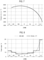
- FIG. 7 is a diagram illustrating an in-furnace temperature distribution when power outputs of all control zones are used in common and a temperature is stabilized.
- FIG. 8 is a diagram illustrating a power output distribution of each control zone according to a comparative example.
- FIG. 9 is a diagram illustrating an in-furnace temperature distribution corresponding to the power distribution of FIG. 8 .
- FIG. 10 is a diagram illustrating a power output distribution in which a power output balance is adjusted by using the resistance circuit in FIG. 6 .
- FIG. 11 is a diagram illustrating an in-furnace temperature distribution corresponding to the power distribution of FIG. 10 .
- FIG. 12 is a diagram illustrating a resistance circuit according to a comparative example.
- FIG. 13 is a diagram illustrating a resistance circuit according to another embodiment (exemplary modification) of the present disclosure.
- FIG. 14 is a diagram illustrating a configuration of a temperature controller according to another embodiment (exemplary modification) of the present disclosure.
- FIG. 15 is a diagram illustrating an example of balance parameters according to another embodiment (exemplary modification) of the present disclosure.
- FIG. 16 is a diagram illustrating a calculation example using parameters having a temperature zone of 600 degrees C. in FIG. 15 .
- FIG. 17 A is a diagram illustrating a power distribution and an in-furnace temperature distribution according to a comparative example
- FIG. 17 B is a diagram illustrating a power distribution and an in-furnace temperature distribution according to an exemplary modification
- FIG. 17 C is a diagram illustrating balance parameters for each control zone.
- a substrate processing apparatus 10 is configured as a processing apparatus which performs a film-forming process in a method of manufacturing a semiconductor device.
- the substrate processing apparatus 10 illustrated in FIG. 1 includes a process tube 11 as a supported vertical reaction tube, and the process tube 11 includes an outer tube 12 and an inner tube 13 disposed to be concentric with each other.
- the outer tube 12 is made of quartz (SiO 2 ), and integrally formed in a cylindrical shape with its upper end closed and its lower end opened.
- the inner tube 13 is formed in a cylindrical shape with both its upper and lower ends opened.
- a hollow cylindrical portion of the inner tube 13 forms a process chamber 14 into which a boat, which will be described later, is loaded, and a lower end opening of the inner tube 13 forms a furnace opening 15 for loading and unloading the boat.
- a boat 31 is configured to hold a plurality of wafers in a long aligned state. Therefore, an inner diameter of the inner tube 13 is set to be larger than a maximum outer diameter (e.g., a diameter of 300 mm) of wafers 1 as substrates to be handled.
- a lower end portion between the outer tube 12 and the inner tube 13 is hermetically sealed by a manifold 16 formed in a substantially cylindrical shape.
- the manifold 16 is detachably attached to each of the outer tube 12 and the inner tube 13 for replacement or the like of the outer tube 12 and the inner tube 13 . Since the manifold 16 is supported by a housing 2 , the process tube 11 is vertically installed.
- the outer tube 12 may be illustrated as the process tube 11 .
- An exhaust passage 17 is formed in a circular ring shape having a fixed width in a cross sectional shape by a gap between the outer tube 12 and the inner tube 13 .
- one end of an exhaust pipe 18 is connected to an upper portion of a sidewall of the manifold 16 , and the exhaust pipe 18 communicates with a lowermost end portion of the exhaust passage 17 .
- An exhaust device 19 controlled by a pressure controller 21 is connected to the other end of the exhaust pipe 18 , and a pressure sensor 20 is connected to the middle of the exhaust pipe 18 .
- the pressure controller 21 is configured to feedback-control the exhaust device 19 based on a measurement result from the pressure sensor 20 .
- a gas introduction pipe 22 is disposed below the manifold 16 so as to communicate with the furnace opening 15 of the inner tube 13 , and a gas supply device 23 configured to supply a precursor gas and an inert gas is connected to the gas introduction pipe 22 .
- the gas supply device 23 is configured to be controlled by a gas flow rate controller 24 .
- a gas introduced from the gas introduction pipe 22 to the furnace opening 15 flows through the process chamber 14 of the inner tube 13 and is exhausted by the exhaust pipe 18 via the exhaust passage 17 .
- a seal cap 25 which closes the lower end opening, is brought into contact with the manifold 16 from the lower side in the vertical direction.
- the seal cap 25 is formed in a disc shape substantially equal to the outer diameter of the manifold 16 , and is configured to be vertically moved up or down by a boat elevator 26 installed in a standby chamber 3 of the housing 2 .
- the boat elevator 26 includes a motor-driven feed screw shaft device, a bellows and the like, and a motor 27 of the boat elevator 26 is configured to be controlled by a driving controller 28 .
- a rotary shaft 30 is disposed on the center line of the seal cap 25 to be rotatably supported, and the rotary shaft 30 is configured to be rotationally driven by a rotation mechanism 29 as a motor controlled by the driving controller 28 .
- the boat 31 is vertically supported on the upper end of the rotary shaft 30 .
- the boat 31 includes a pair of upper and lower end plates 32 and 33 , and three holding members 34 vertically installed between the end plates 32 and 33 , and a plurality of holding grooves 35 are formed at equal intervals in a longitudinal direction in the three holding members 34 .
- the holding grooves 35 , 35 and 35 formed in the same stages in the three holding members 34 are opened facing each other.
- the boat 31 is configured to hold the plurality of wafers 1 , in such a state that the wafers 1 are horizontally arranged with the centers of the wafers aligned with one another, by inserting the wafers among the holding grooves 35 of the same stages of the three holding members 34 .
- a heat insulating cap part 36 is disposed between the boat 31 and the rotary shaft 30 .
- the rotary shaft 30 is configured to support the boat 31 lifted up from the upper surface of the seal cap 25 so that the lower end of the boat 31 is separated from the position of the furnace opening 15 by an appropriate distance.
- the heat insulating cap part 36 is configured to heat-insulate the vicinity of the furnace opening 15 .
- a heater unit 40 as a heating part (or a heater) is disposed outside the process tube 11 in a concentric relationship with the process tube 11 and is installed to be supported by the housing 2 .
- the heater unit 40 includes a case 41 .
- the case 41 is made of stainless steel (SUS) and has a tubular shape or a cylindrical shape in some embodiments with its upper end closed and its lower end opened.
- the inner diameter and the entire length of the case 41 are set larger than the outer diameter and the entire length of the outer tube 12 .
- SUS stainless steel
- the heater unit 40 is divided into seven control zones U 1 , U 2 , CU, C, CL, L 1 and L 2 as a plurality of heating regions (heating control zones) from an upper end side to a lower side of the heater unit 40 .
- a heat insulating structure 42 which is an embodiment of the present disclosure, is installed in the case 41 .
- the heat insulating structure 42 according to the present embodiment has a tubular shape or a cylindrical shape in some embodiment, and a sidewall portion 43 of the cylindrical body is formed in a multi-layer structure. That is, the heat insulating structure 42 includes a sidewall outer layer 45 disposed outside the sidewall portion 43 and a sidewall inner layer 44 disposed inside the sidewall portion 43 , and further includes a partition portion 105 configured to separate the sidewall portion 43 into a plurality of zones (regions) in the vertical direction between the sidewall outer layer 45 and the sidewall inner layer 44 and an annular buffer 106 as a buffer part installed between the partition portion 105 and its adjacent partition portion 105 .
- the annular buffer 106 is configured to be divided according to its length into a plurality of portions by a partition portion 106 a as a slit. That is, the partition portion 106 a is installed to separate the annular buffer 106 into the plurality of portions according to the length of the zones.
- the partition portion 105 will be referred to as a first partition portion 105 and the partition portion 106 a will be referred to as a second partition portion 106 a .
- the partition portion 105 may be referred to as a separation portion configured to separate the partition portion 105 into a plurality of cooling zones.
- the control zones CU, C, CL, L 1 and L 2 and the annular buffer 106 described above are installed so as to face each other, and it is configured so that a height of each control zone and a height of the annular buffer 106 are substantially equal to each other.
- it is configured so that the heights of the control zones U 1 and U 2 described above are different from the height of the annular buffer 106 facing these control zones.
- cooling air 90 can be efficiently supplied to each control zone.
- the cooling air 90 can be efficiently supplied to the control zone U 1 . This makes it possible to perform the same temperature control as that in the other control zones even in the control zone U 1 closest to the exhaust side.
- the partition portion 105 disposed in the uppermost portion is at a position higher than a substrate processing region of the boat 31 and lower than the height of the process tube 11 (a position substantially equal to the height of the inner tube 13 ), and the partition portion 105 disposed in the second uppermost portion is at a position substantially equal to that of the wafer 1 held on the upper end portion of the boat 31 , the cooling air 90 can be efficiently brought into contact with the exhaust side of the process tube 11 (a portion on which the wafer 1 is not held), thereby performing cooling like the process tube 11 corresponding to the substrate processing region of the boat 31 . As a result, the entire process tube 11 can be uniformly cooled.
- a check damper 104 as a back diffusion prevention part is installed in each zone. Furthermore, it is configured so that the cooling air 90 is supplied to the annular buffer 106 via a gas introduction path 107 by opening and closing a back diffusion prevention body 104 a . Then, it is configured so that the cooling air 90 supplied to the annular buffer 106 flows through a gas supply passage installed in a sidewall inner layer 44 (not shown in FIG. 2 ) and is supplied from an opening hole, which is a portion of a supply path including the gas supply passage, to the inner space 75 .
- the back diffusion prevention body 104 a is configured to serve as a lid so that an atmosphere of the inner space 75 does not flow backward.
- An open pressure of the back diffusion prevention body 104 a may be changed according to the zone.
- a heat insulating cloth 111 as a blanket is installed between the outer peripheral surface of the sidewall outer layer 45 and the inner peripheral surface of the case 41 so as to absorb a thermal expansion of metal.
- the cooling air 90 supplied to the annular buffer 106 flows through the gas supply passage installed in the sidewall inner layer 44 (not shown in FIG. 2 ) and is supplied from the opening hole to the inner space 75 .
- the upper end side of the sidewall portion 43 of the heat insulating structure 42 is covered with a ceiling wall portion 80 as a ceiling portion so as to close the inner space 75 .
- An exhaust port 81 as a portion of an exhaust passage configured to exhaust the atmosphere of the inner space 75 is annually formed in the ceiling wall portion 80 , and a lower end which is an upstream side end of the exhaust port 81 communicates with the inner space 75 .
- a downstream side end of the exhaust port 81 is connected to the exhaust duct 82 .
- the seal cap 25 is raised by the boat elevator 26 such that the boat 31 holding a group of wafers 1 is loaded into the process chamber 14 of the inner tube 13 (boat loading).
- the seal cap 25 reaching an upper limit is pressed and brought into contact with the manifold 16 so as to seal interior of the process tube 11 .
- the boat 31 supported by the seal cap 25 is kept in the process chamber 14 .
- thermocouples 65 are installed near the heating element 56 for each of the control zones U 1 , U 2 , CU, C, CL, L 1 and L 2 illustrated in FIG. 2 . Details of a configuration and a control of the heater unit 40 will be described later.
- thermocouples may be installed in the process tube 11 .
- the precursor gas is introduced into the process chamber 14 of the process tube 11 from the gas introduction pipe 22 by the gas supply device 23 .
- the precursor gas introduced by the gas introduction pipe 22 flows through the process chamber 14 of the inner tube 13 and is exhausted by the exhaust pipe 18 via the exhaust passage 17 .
- a predetermined film is formed on each of the wafers 1 by a thermal CVD reaction by the contact of the precursor gas with the wafers 1 heated to a predetermined processing temperature when flowing through the process chamber 14 .
- the cooling air 90 as a cooling gas is supplied from an intake pipe 101 to the gas introduction path 107 via the back diffusion prevention body 104 a .
- the supplied cooling air 90 is temporarily stored in the annular buffer 106 and is injected from a plurality of opening holes 110 to the inner space 75 via a gas supply passage 108 .
- the cooling air 90 injected from the opening 110 to the inner space 75 is exhausted by the exhaust port 81 and the exhaust duct 82 .
- the cooling air 90 can be used as the cooling gas.
- an inert gas such as a nitrogen gas or the like may be used as the cooling gas in order to further enhance the cooling effect or to prevent corrosion of the heating element 56 at a high temperature due to an impurity in the air.
- the aforementioned operation is repeatedly performed so that the film-forming process is performed on the wafers 1 by the substrate processing apparatus 10 .
- a control computer 200 as a control part includes a computer main body 203 including a central processing unit (CPU) 201 , a memory 202 and the like, a communication interface (IF) 204 as a communication part, and a storage device 205 as a storage part, and a display/input device 206 as an operation part. That is, the control computer 200 includes a configuration part as a general computer.
- the CPU 201 which constitutes the center of the operation part, executes a control program stored in the storage device 205 , and executes a recipe (for example, a process recipe) recorded in the storage device 205 according to an instruction from the display/input device 206 .
- a recipe for example, a process recipe
- the process recipe includes temperature control from step S 1 to step S 6 , which will be described later, illustrated in FIG. 4 .
- a read only memory ROM
- an electrically erasable programmable read only memory EEPROM
- a flash memory a hard disk, or the like
- a random access memory RAM functions as a work area or the like of the CPU.
- the communication IF 204 is electrically connected to the pressure controller 21 , the gas flow rate controller 24 , the driving controller 28 , and the temperature controller 64 (these controllers may be generally referred to as a sub controller), and can exchange data on operations of respective components. Further, it is also electrically connected to a valve control part 300 , which will be described later, so as to exchange data for controlling a multi-cooling unit.
- control computer 200 has been described as an example in the embodiment of the present disclosure, the present disclosure is not limited thereto but may be realized using a normal computer system.
- the aforementioned processing may be executed by installing a program from the recording medium 207 such as a CDROM, a USB or the like storing the program for executing the aforementioned processing, on a general-purpose computer.
- the communication IF 204 including a communication line, a communication network, a communication system, and the like may be used.
- the program may be posted on a bulletin board of the communication network, and may be provided by being superimposed on a carrier wave via the network.
- the aforementioned processing may be executed by activating the program thus provided and executing the same under the control of an operating system (OS) in the same manner as other application programs.
- OS operating system
- Reference numerals S 1 to S 6 shown in FIG. 5 indicate that steps S 1 to S 6 in FIG. 4 are performed.
- Step S 1 is a process of stabilizing the in-furnace temperature to a relatively low temperature T 0 .
- the wafer 1 has not yet been inserted into the furnace.
- Step S 2 is a process of inserting the wafer 1 held in the boat 31 into the furnace. Since the temperature of the wafer 1 is lower than the in-furnace temperature T 0 at this time, the in-furnace temperature is temporarily lower than T 0 as a result of inserting the wafer 1 into the furnace, but the in-furnace temperature is stabilized to the temperature T 0 again after an elapse of some time by the temperature controller 64 or the like. For example, when the temperature T 0 is a room temperature, this step may be omitted and it is not an essential step.
- Step S 3 is a process of raising the in-furnace temperature by the heater unit 40 from the temperature T 0 to a target temperature T 1 for performing the film-forming process on the wafer 1 .
- Step S 4 is a process of maintaining and stabilizing the in-furnace temperature to the target temperature T 1 in order to perform the film-forming process on the wafer 1 .
- Step S 5 is a process of gradually lowering the in-furnace temperature from the temperature T 1 to the relatively low temperature T 0 again by the cooling unit 100 and the heater unit 40 , which will be described later, after the film-forming process is completed. Furthermore, the in-furnace temperature may be rapidly cooled from the processing temperature T 1 to the temperature T 0 by the cooling unit 100 while turning off the heater unit 40 .
- Step S 6 is a process of taking out the wafer 1 on which the film-forming process has been performed from the interior of the furnace together with the boat 31 .
- steps S 1 to S 6 obtain a stable state in which the in-furnace temperature is within a predetermined minute temperature range with respect to the target temperature and continues for a predetermined time, and then proceed to a next step.
- the process may proceed to the next step without obtaining a stable state at steps S 1 , S 2 , S 5 , S 6 , and the like.
- the heater unit 40 has a resistance circuit installed for each of the control zones U 1 , U 2 , CU, C, CL, L 1 and L 2 .
- FIG. 6 illustrates resistance circuits of the control zones CU and C
- the control zones U 2 , CU, CL and L 1 have the same configuration as the control zone C. Since U 1 and L 2 are not parallel circuits, they have different circuit configurations from CU and C.
- Each resistance circuit includes at least the heating element 56 configured to raise the internal temperature of the process tube 11 by heat generation, in which resistance values of the heating elements 56 in the respective control zones are set to be equalized.
- the heating elements 56 as heat generation parts are divided into the plurality of control zones U 1 , U 2 , CU, C, CL, L 1 and L 2 .
- the heating elements 56 each include, for example, a resistive heater such as a carbon heater or the like.
- a resistance circuit 51 as an output circuit in the control zone CU is a parallel circuit including heating elements 56 a - 1 and 56 b - 1 wired in parallel between terminals 51 a and 51 b .
- the heating elements 56 in the control zone CU are configured as the heating elements 56 a - 1 and 56 b - 1 having the same resistance value. More specifically, one end of the heating element 56 a - 1 is connected to the terminal 51 a and the other end thereof is connected to the terminal 51 b . Furthermore, one end of the heating element 56 b - 1 is connected to the terminal 51 b , and the other end thereof is connected to the terminal 51 a via a power regulator 51 c which is an output variable element.
- electric power output to the heating element 56 a and electric power output to the heating element 56 b - 1 can be made different from each other.
- the power regulator 51 c is a resistor having a predetermined resistance value
- the electric power output to the heating element 56 a - 1 can be made larger than the electric power output to the heating element 56 b - 1 .
- the heating element 56 a - 1 is disposed at an upper side of the control zone CU, and the heating element 56 b - 1 is disposed at a lower side of the control zone CU. Therefore, the electric power output to the heating element 56 a - 1 at the upper side of the control zone CU can be made larger than the electric power output to the heating element 56 b - 1 at the lower side of the control zone CU, thereby outputting different electric powers to the heating elements in the vertical direction in the control zone CU.
- the heating element driving device 63 supplies a voltage obtained by adjusting an output of an AC power source 63 a - 1 by a power regulator 63 b to between the terminals 51 a and 51 b .
- the power regulator 63 b includes a thyristor having an anode connected to one end of the AC power source 63 a - 1 , a cathode being connected to the terminal 51 a , and a gate to which a control signal from the temperature controller 64 is input.
- the other end of the AC power source 63 a - 1 is connected to the terminal 51 b.
- a resistance circuit 52 as an output circuit in the control zone C is a parallel circuit including heating elements 56 a - 2 and 56 b - 2 wired in parallel between terminals 52 a and 52 b .
- the heating elements 56 in the control zone C also include the heating elements 56 a - 2 and 56 b - 2 . More specifically, one end of the heating element 56 a - 2 is connected to the terminal 52 a and the other end thereof is connected to the terminal 52 b . Furthermore, one end of the heating element 56 b - 2 is connected to the terminal 52 b and the other end thereof is connected to the terminal 52 a via a power regulator 52 c which is an output variable element.
- electric power output to the heating element 56 a - 2 and electric power output to the heating element 56 b - 2 can be made different from each other.
- the power regulator 52 c is a resistor having a predetermined resistance value
- the electric power output to the heating element 56 a - 2 can be made larger than the electric power output to the heating element 56 b - 2 .
- the heating element 56 b - 2 is disposed at an upper side of the control zone C, and the heating element 56 a - 2 is disposed at a lower side of the control zone C. Therefore, the electric power output to the heating element 56 b - 2 at the upper side of the control zone C can be made smaller than the electric power output to the heating element 56 a - 2 at the lower side of the control zone C, thereby outputting different electric powers to the heating elements in the vertical direction in the control zone C.
- the heating element driving device 63 supplies a voltage obtained by adjusting an output of an AC power source 63 a - 2 by a power regulator 63 c to between the terminals 52 a and 52 b .
- the power regulator 63 c includes a thyristor having an anode connected to one end of the AC power source 63 a - 2 , a cathode being connected to the terminal 52 a , and a gate to which a control signal from the temperature controller 64 is input.
- the other end of the AC power source 63 a - 2 is connected to the terminal 52 b.
- heating elements are connected in parallel, but three or more heating elements may be connected in parallel. That is, two or more heating elements are arranged and wired in each control zone.
- the power regulator may be installed in at least one heating element. That is, the resistance circuits 51 and 52 are parallel circuits, and the power regulators 51 c and 52 c are configured to be installed in one or more of circuits constituting the parallel circuits.
- the temperature controller 64 adjusts the electric power supplied to the heating elements 56 based on the temperature detected by the thermocouples 65 , and controls the temperature to the detected temperature. Further, the temperature controller 64 supplies different electric powers to the resistance circuit of each control zone by supplying different voltages to the terminals of the resistance circuit of each control zone. In addition, since the resistance circuit is configured to make the electric power output to a circuit in which the power regulator is not installed larger than the electric power output to a circuit to which the power regulator is connected, the temperature controller 64 can supply different electric power to each of the circuits constituting the parallel circuit in each control zone only by supplying the voltage to the terminals of the resistance circuit of each control zone. Thus, the temperature controller 64 can supply different electric powers in the vertical direction in each control zone.
- FIG. 7 illustrates an in-furnace temperature distribution in a stabilized temperature state when power outputs (wall surface load densities) of all the control zones are used in common.
- the wall surface load density indicates a heater output per unit area of the wall surface. An N 2 gas was supplied into the furnace at this time, and an in-furnace pressure is 33 Pa.
- a method of power balance adjustment in the control zones of the heater unit 40 will be described with reference to FIGS. 8 to 12 .
- the power outputs of the control zones U 1 , U 2 , CU, C, CL, L 1 and L 2 are adjusted so that the temperature distribution of the control zones U 2 , CU, C, CL and L 1 located in a wafer region becomes uniform.
- FIG. 8 illustrates a power output distribution of control zones U 1 , U 2 , CU, C, CL, L 1 and L 2 according to a comparative example adjusted so that the temperature distribution of a wafer region of the control zones U 2 , CU, C, CL and L 1 becomes uniform.
- the power regulator 51 c is not installed between the heating element 56 b and the terminal 51 a and the power regulator 52 c is not installed between the heating element 56 b and the terminal 52 a , unlike the resistance circuits 51 and 52 according to the embodiment in FIG. 6 .
- the heating element 56 a and the heating element 56 b have the same resistance value and thus the power outputs in the respective control zones are constant, a stepwise power output distribution as shown in FIG. 8 is obtained.
- this power distribution is shown as a solid line REALITY.
- an ideal power output distribution for making the in-furnace temperature uniform is shown as a broken line DREAM.
- the DREAM is an estimated value based on the temperature distribution of FIG. 7 and an actual power measurement value of FIG. 8 .
- the REALTY shows that the power outputs are provided to match DREAM near the center of the control zones. A difference between REALITY and DREAM becomes larger as it goes to the upper and lower control zones of the process tube 11 .
- FIG. 9 illustrates an in-furnace temperature distribution corresponding to the power distribution of FIG. 8 . Similar to FIG. 7 , an N 2 gas is supplied into the furnace at this time, and an in-furnace pressure is 33 Pa. A temperature difference of 0.4 to 1.0 degrees C. as shown in FIG. 9 occurs due to a difference between the REALITY and the DREAM in FIG. 8 .
- a solid line NEW in FIG. 10 indicates a power output distribution in which the power output balance is adjusted using the resistance circuits in FIG. 6 .
- a broken line DREAM in FIG. 10 indicates an ideal power output distribution equal to the DREAM in FIG. 8 .
- the output power of the upper heating element 56 a is set larger than the output power of the lower heating element 56 b using the resistance circuit in FIG. 6 .
- the resistance circuit of the control zone U 2 is similar to the resistance circuit 51 of the control zone CU in FIG. 7 , and the output power of the upper heating element is set larger than the output power of the lower heating element.
- the resistance circuit of the control zone U 1 is similar to the resistance circuit 61 of the control zone CU in FIG. 12 , and the output powers of the upper and lower heating elements are set equal.
- the output power of the lower heating element 56 a is set larger than the output power of the upper heating element 56 a using the resistance circuit in FIG. 6 .
- the resistance circuit of the control zone CL is similar to the resistance circuit 52 of the control zone C in FIG. 6 , and the output power of the lower heating element is set larger than the output power of the upper heating element.
- the resistance circuit of the control zone L 1 is similar to the resistance circuit 52 of the control zone C in FIG. 7 , and the output power of the lower heating element is set larger than the output power of the upper heating element.
- the resistance circuits of the control zones U 1 and L 2 are connected in series, and the output powers of the upper and lower heating elements are set equal.
- a power output distribution as indicated by NEW in FIG. 10 can be obtained.
- the NEW shows that the power outputs are provided to match DREAM near the center.
- the NEW shows that the power outputs are provided to match DREAM near the center of each of the upper side and the lower side.
- a difference between the NEW and the DREAM in FIG. 10 may be made smaller than the difference between the REALITY and the DREAM in FIG. 8 .
- FIG. 11 illustrates an in-furnace temperature distribution in the power output distribution of FIG. 10 .
- an N 2 gas is supplied into the furnace at this time, and an in-furnace pressure is 33 Pa.
- a temperature difference in the wafer region of the respective control zones U 2 , CU, C, CL and L 1 is set at 0.2 degrees C. or lower, and thus the uniformity of the in-furnace temperature distribution is improved compared with the comparative example.
- the present embodiment since not only the power outputs among the respective control zones in the wafer region but also the power outputs in the respective control zones can be adjusted, it is possible to make the in-furnace temperature distribution uniform among the wafers.
- FIG. 11 illustrates an in-furnace temperature distribution in the power output distribution of FIG. 10 .
- an interior of each of the control zones U 2 , CU, C, CL and L 1 is configured to be divided into two parts, but the present disclosure is not limited thereto, and the number of divisions in the respective control zone U 2 , CU, C, CL and L 1 may be respectively set. Thus, the number of divisions can be set different in the respective control zones U 2 , CU, C, CL and L 1 .
- FIG. 13 illustrates resistance circuits in which the power regulators include thyristors.
- a resistance circuit 71 as an output circuit in the control zone CU is a parallel circuit including heating elements 56 a - 1 and 56 b - 1 wired in parallel between terminals 51 f and 51 b .
- the heating elements 56 in the control zone CU include the heating elements 56 a - 1 and 56 b - 1 having the same resistance value. More specifically, one end of the heating element 56 a - 1 is connected to the terminal 51 f via the terminal 51 a and the power regulator 63 b , and the other end thereof is connected to the terminal 51 b .
- one end of the heating element 56 b - 1 is connected to the terminal 51 b , and the other end thereof is connected to the terminal 51 f via a power regulator 51 e which is an output variable element.
- the power regulator 51 e includes a thyristor like the power regulator 63 b.
- the resistance circuit 71 includes a part of the heater unit 40 and a part of the heating element driving device 63 . That is, unlike the resistance circuit 51 , the resistance circuit 71 includes the power regulator 51 e .
- the resistance circuit 71 supplies a voltage obtained by adjusting an output of an AC power source 63 a by the power regulator 63 b based on a control signal from the temperature controller 64 to between the terminals 51 a and 51 b . Further, it supplies a voltage obtained by adjusting the output of the AC power source 63 a by the power regulator 51 e based on the control signal from the temperature controller 64 to between the terminals 51 d and 51 b . Since the heating element 56 a - 1 and the heating element 56 b - 1 use the terminal 51 b in common and are supplied with electric power from the in-phase AC power source 63 a , the resistance circuit 71 is also a kind of parallel circuit.
- the electric power output to the heating element 56 a - 1 and the electric power output to the heating element 56 b - 1 can be made different.
- the electric power output to the heating element 56 a - 1 can be made larger than the power output to the heating element 56 b - 1 .
- the heating element 56 a - 1 is disposed at an upper side of the control zone CU, and the heating element 56 b - 1 is disposed at a lower side of below the control zone CU. Therefore, the electric power output to the heating element 56 a - 1 at the upper side of the control zone CU can be made larger than the electric power output to the heating element 56 b - 1 at the lower side of the control zone CU, thereby outputting different electric powers to the heating elements in the vertical direction in the control zone CU.
- the resistance circuit 72 in the control zone C is a parallel circuit including the heating elements 56 a - 2 and 56 b - 2 wired in parallel between the terminal 52 f and 52 b .
- the heating elements 56 in the control zone C include the heating elements 56 a - 2 and 56 b - 2 having the same resistance value. More specifically, one end of the heating element 56 a - 2 is connected to the terminal 52 f via the terminal 52 a and the power regulator 63 c , and the other end thereof is connected to the terminal 52 b . Furthermore, one end of the heating element 56 b - 2 is connected to the terminal 52 b , and the other end thereof is connected to the terminal 52 f via the power regulator 52 e which is an output variable element.
- the power regulator 52 e include a thyristor, like the power regulator 63 c.
- the resistance circuit 72 includes a part of the heater unit 40 and a part of the heating element driving device 63 . That is, unlike the resistance circuit 52 , the resistance circuit 72 includes the power regulator 63 c .
- the resistance circuit 72 supplies electric power obtained by adjusting the output of the AC power source 63 a by the electric power regulator 52 e based on the control signal from the temperature controller 64 to between the terminals 52 a and 52 b . Further, it supplies electric power obtained by adjusting the output of the AC power source 63 a by the power regulator 52 e based on the control signal from the temperature controller 64 to between the terminals 52 d and 52 b.
- the electric power output to the heating element 56 a - 2 and the electric power output to the heating element 56 b - 2 may be made different.
- the electric power output to the heating element 56 a - 2 can be made larger than the electric power output to the heating element 56 b - 2 .
- the heating element 56 b - 2 is disposed at an upper side of the control zone C, and the heating element 56 a - 2 is disposed at a lower side of the control zone C. Therefore, the electric power output to the heating element 56 b - 2 at the upper side of the control zone C can be made different from, such as being smaller than the electric power output to the heating element 56 a - 2 at the lower side of the control zone C, thereby outputting different electric powers to the two heating elements in the vertical direction in the control zone C.
- the temperature controller 64 takes a temperature detected by a temperature detection part (or a temperature detector) 641 (thermocouples 65 in FIG. 2 ). Further, the temperature controller 64 receives balance parameters, in addition to a set temperature value from the control computer 200 as a higher controller.
- the control computer 200 sets upper and lower output ratios as the balance parameters for one control zone.
- the upper output ratio will be referred to as Upper_Ratio and the lower output ratio will be referred to as Lower_Ratio.
- the balance parameters can be switched according to an instruction from the control computer 200 by holding parameters for each temperature zone.
- a power balance adjustment part (or an adjuster) 642 determines upper and lower outputs for one control zone.
- FIG. 15 illustrates a numerical example of the balance parameters of the CU zone among the control zones.
- a temperature control calculation part (or a temperature control calculator) 643 performs temperature control calculation such that the set temperature instructed by the control computer 200 and the temperature detected by the temperature detection part 641 match, to determine a control calculation result.
- the power balance adjustment part 642 determines upper and lower electric powers (effective values) for one control zone by the following equations (1) to (3).
- Upper power output control calculation result ⁇ Upper_Ratio Eq.
- Lower power output control calculation result ⁇ Lower_Ratio Eq.
- Upper_ratio+Lower_Ratio 2.0 Eq. (3)
- FIG. 16 illustrates an example of calculation using the parameters in which the temperature zone in FIG. 15 is 600 degrees C.
- the balance parameters can be switched according to an instruction from the control computer 200 by holding a plurality of parameters for each temperature zone as illustrated in FIG. 15 . Further, by setting more than two balance parameters for one control zone, it is also easy to supply different electric powers for finer zone division.
- FIG. 17 A shows an in-furnace temperature distribution and electric power of each control zone according to a comparative example
- FIG. 17 B shows an in-furnace temperature distribution and electric power of each control zone according to the modification
- FIG. 17 C is an example of balance parameters indicating power balance in a product region of control zones U 2 to L 1 .
- each output circuit since the electric power output from each output circuit can be adjusted by installing the plurality of output circuits in each control zone, the interior of each control zone is divided and different wall surface load densities can be output. Therefore, the temperature difference within the wafer region of the respective control zones U 2 , CU, C, CL and L 1 with respect to the target temperature can be suppressed to 0.2 degrees C. or lower.
- FIGS. 17 A to 17 C as an example, by reducing Lower_Ratio of the CU zone, the influence from the CU zone to the C zone is reduced, and the (temperature) waveform near a boundary between the CU zone and the C zone (at an upper portion of the C zone) is lowered.
- the C zone becomes kept within 0.2 degrees C.
- the waveform near the boundary between the CL zone and the L 1 zone is lowered such that the waveform of the entire CL zone is lowered.
- the CL zone is kept 0.2 degrees C. or below.
- the balance parameters are set in consideration of the influence of the temperature waveforms of such adjacent respective zones, the temperature difference within the wafer region of the respect zones can be reduced to near close to 0 degrees C.
- a control zone expansion method in which two control zones are used may be considered as a method of applying different electric powers to the upper portion and the lower portion of one control zone.
- Advantages of this modification may be as follows by comparing the control zone expansion method and this modification.
- thermocouples and the temperature detection part are respectively included in one control zone, but since a plurality of outputs can be calculated by the power balance adjustment part, it is superior in terms of cost compared with the control zone expansion method.
- the present disclosure may be applied not only to the semiconductor manufacturing apparatus but also to an apparatus for processing a glass substrate such as an LCD device.
- the present disclosure is directed to a semiconductor manufacturing technique, particularly, to a heat treatment technique in which a substrate to be processed is accommodated in a process chamber and processed in a state where it is heated by a heating device, and may be effectively applied to a substrate processing apparatus used for an oxidation process, a diffusion process, reflow for carrier activation and flattening after ion implantation, a film-forming process by annealing and thermal CVD reaction or the like, for example, on a semiconductor wafer in which a semiconductor integrated circuit device (semiconductor device) is built in.
- a semiconductor integrated circuit device semiconductor integrated circuit device
Landscapes
- Engineering & Computer Science (AREA)
- Manufacturing & Machinery (AREA)
- Mechanical Engineering (AREA)
- General Engineering & Computer Science (AREA)
Abstract
Description
Upper power output=control calculation result×Upper_Ratio Eq. (1)
Lower power output=control calculation result×Lower_Ratio Eq. (2)
Upper_ratio+Lower_Ratio=2.0 Eq. (3)
Upper power output=75.0%×1.07=80.25%
Lower power output=75.0%×0.93=69.75%
Claims (18)
Priority Applications (1)
| Application Number | Priority Date | Filing Date | Title |
|---|---|---|---|
| US18/790,300 US20240393050A1 (en) | 2019-06-12 | 2024-07-31 | Heater, temperature control system, and processing apparatus |
Applications Claiming Priority (4)
| Application Number | Priority Date | Filing Date | Title |
|---|---|---|---|
| JP2019-109838 | 2019-06-12 | ||
| JP2019109838 | 2019-06-12 | ||
| JP2020073076A JP7101718B2 (en) | 2019-06-12 | 2020-04-15 | Manufacturing method for heating unit, temperature control system, processing equipment and semiconductor equipment |
| JP2020-073076 | 2020-04-15 |
Related Child Applications (1)
| Application Number | Title | Priority Date | Filing Date |
|---|---|---|---|
| US18/790,300 Continuation US20240393050A1 (en) | 2019-06-12 | 2024-07-31 | Heater, temperature control system, and processing apparatus |
Publications (2)
| Publication Number | Publication Date |
|---|---|
| US20200393197A1 US20200393197A1 (en) | 2020-12-17 |
| US12085338B2 true US12085338B2 (en) | 2024-09-10 |
Family
ID=73734980
Family Applications (2)
| Application Number | Title | Priority Date | Filing Date |
|---|---|---|---|
| US16/899,041 Active 2041-06-29 US12085338B2 (en) | 2019-06-12 | 2020-06-11 | Heater, temperature control system, and processing apparatus |
| US18/790,300 Pending US20240393050A1 (en) | 2019-06-12 | 2024-07-31 | Heater, temperature control system, and processing apparatus |
Family Applications After (1)
| Application Number | Title | Priority Date | Filing Date |
|---|---|---|---|
| US18/790,300 Pending US20240393050A1 (en) | 2019-06-12 | 2024-07-31 | Heater, temperature control system, and processing apparatus |
Country Status (2)
| Country | Link |
|---|---|
| US (2) | US12085338B2 (en) |
| CN (1) | CN112086378B (en) |
Families Citing this family (2)
| Publication number | Priority date | Publication date | Assignee | Title |
|---|---|---|---|---|
| US11703229B2 (en) * | 2018-12-05 | 2023-07-18 | Yi-Ming Hung | Temperature adjustment apparatus for high temperature oven |
| CN117542767B (en) * | 2024-01-10 | 2024-03-26 | 合肥费舍罗热工装备有限公司 | Vertical semiconductor welding furnace |
Citations (19)
| Publication number | Priority date | Publication date | Assignee | Title |
|---|---|---|---|---|
| US4484243A (en) * | 1982-09-30 | 1984-11-20 | General Electric Company | Protective circuit arrangement for a sheathed heating element |
| JPH0778830A (en) | 1993-09-07 | 1995-03-20 | Hitachi Ltd | Semiconductor manufacturing equipment |
| JPH11195610A (en) | 1998-01-05 | 1999-07-21 | Kokusai Electric Co Ltd | Semiconductor manufacturing equipment |
| JP2000223427A (en) | 1999-02-02 | 2000-08-11 | Kokusai Electric Co Ltd | Heater abnormality detection method for semiconductor manufacturing equipment |
| JP2000339039A (en) | 1999-05-25 | 2000-12-08 | Tokyo Electron Ltd | Temperature control method of heating means, apparatus therefor and heat treatment apparatus |
| US6352594B2 (en) * | 1997-08-11 | 2002-03-05 | Torrex | Method and apparatus for improved chemical vapor deposition processes using tunable temperature controlled gas injectors |
| JP2002093714A (en) | 2000-09-11 | 2002-03-29 | Hitachi Kokusai Electric Inc | Semiconductor manufacturing equipment |
| JP2004288775A (en) | 2003-03-20 | 2004-10-14 | Hitachi Kokusai Electric Inc | Semiconductor manufacturing equipment |
| KR20050088989A (en) | 2005-02-17 | 2005-09-07 | 도쿄 엘렉트론 가부시키가이샤 | Heat treatment system and heat treatment method |
| US20060054616A1 (en) * | 2004-09-15 | 2006-03-16 | Kevin Ptasienski | Adaptable layered heater system |
| US20070039938A1 (en) * | 2005-08-19 | 2007-02-22 | Peck Kevin B | Fault tolerant element and combination with fault tolerant circuit |
| JP2009281837A (en) | 2008-05-21 | 2009-12-03 | Tokyo Electron Ltd | Wire breaking prediction apparatus and thermal treatment apparatus of electric power using system |
| JP2011108596A (en) | 2009-11-20 | 2011-06-02 | Kokusai Electric Semiconductor Service Inc | Power supply system |
| US20120223066A1 (en) * | 2011-03-01 | 2012-09-06 | Tokyo Electron Limited | Thermal processing apparatus and method of controlling the same |
| US20130065189A1 (en) | 2011-09-13 | 2013-03-14 | Tokyo Electron Limited | Thermal treatment apparatus, temperature control system, thermal treatment method, temperature control method, and non-transitory computer readable medium embodied with program for executing the thermal treatment method or the temperature control method |
| WO2018100826A1 (en) | 2016-11-30 | 2018-06-07 | 株式会社日立国際電気 | Substrate processing device, method of manufacturing semiconductor device, and program |
| WO2018105113A1 (en) | 2016-12-09 | 2018-06-14 | 株式会社日立国際電気 | Substrate processing device, cooling unit, and heat insulating structure |
| WO2018182013A1 (en) | 2017-03-31 | 2018-10-04 | 国立大学法人横浜国立大学 | Heating-type light source |
| US11088002B2 (en) * | 2018-03-29 | 2021-08-10 | Asm Ip Holding B.V. | Substrate rack and a substrate processing system and method |
Family Cites Families (3)
| Publication number | Priority date | Publication date | Assignee | Title |
|---|---|---|---|---|
| US20030049372A1 (en) * | 1997-08-11 | 2003-03-13 | Cook Robert C. | High rate deposition at low pressures in a small batch reactor |
| JP5632190B2 (en) * | 2009-07-02 | 2014-11-26 | 株式会社日立国際電気 | Semiconductor device manufacturing method, substrate manufacturing method, and substrate processing apparatus |
| JP6752851B2 (en) * | 2017-09-12 | 2020-09-09 | 株式会社Kokusai Electric | Manufacturing methods for cooling units, substrate processing equipment, and semiconductor equipment |
-
2020
- 2020-06-08 CN CN202010515304.7A patent/CN112086378B/en active Active
- 2020-06-11 US US16/899,041 patent/US12085338B2/en active Active
-
2024
- 2024-07-31 US US18/790,300 patent/US20240393050A1/en active Pending
Patent Citations (22)
| Publication number | Priority date | Publication date | Assignee | Title |
|---|---|---|---|---|
| US4484243A (en) * | 1982-09-30 | 1984-11-20 | General Electric Company | Protective circuit arrangement for a sheathed heating element |
| JPH0778830A (en) | 1993-09-07 | 1995-03-20 | Hitachi Ltd | Semiconductor manufacturing equipment |
| US6352594B2 (en) * | 1997-08-11 | 2002-03-05 | Torrex | Method and apparatus for improved chemical vapor deposition processes using tunable temperature controlled gas injectors |
| JPH11195610A (en) | 1998-01-05 | 1999-07-21 | Kokusai Electric Co Ltd | Semiconductor manufacturing equipment |
| JP2000223427A (en) | 1999-02-02 | 2000-08-11 | Kokusai Electric Co Ltd | Heater abnormality detection method for semiconductor manufacturing equipment |
| JP2000339039A (en) | 1999-05-25 | 2000-12-08 | Tokyo Electron Ltd | Temperature control method of heating means, apparatus therefor and heat treatment apparatus |
| JP2002093714A (en) | 2000-09-11 | 2002-03-29 | Hitachi Kokusai Electric Inc | Semiconductor manufacturing equipment |
| JP2004288775A (en) | 2003-03-20 | 2004-10-14 | Hitachi Kokusai Electric Inc | Semiconductor manufacturing equipment |
| US20060054616A1 (en) * | 2004-09-15 | 2006-03-16 | Kevin Ptasienski | Adaptable layered heater system |
| KR20050088989A (en) | 2005-02-17 | 2005-09-07 | 도쿄 엘렉트론 가부시키가이샤 | Heat treatment system and heat treatment method |
| US20070039938A1 (en) * | 2005-08-19 | 2007-02-22 | Peck Kevin B | Fault tolerant element and combination with fault tolerant circuit |
| TW200718263A (en) | 2005-08-19 | 2007-05-01 | Mrl Ind Inc | Fault tolerant element and combination with fault tolerant circuit |
| JP2009281837A (en) | 2008-05-21 | 2009-12-03 | Tokyo Electron Ltd | Wire breaking prediction apparatus and thermal treatment apparatus of electric power using system |
| JP2011108596A (en) | 2009-11-20 | 2011-06-02 | Kokusai Electric Semiconductor Service Inc | Power supply system |
| US20120223066A1 (en) * | 2011-03-01 | 2012-09-06 | Tokyo Electron Limited | Thermal processing apparatus and method of controlling the same |
| US20130065189A1 (en) | 2011-09-13 | 2013-03-14 | Tokyo Electron Limited | Thermal treatment apparatus, temperature control system, thermal treatment method, temperature control method, and non-transitory computer readable medium embodied with program for executing the thermal treatment method or the temperature control method |
| KR20130029009A (en) | 2011-09-13 | 2013-03-21 | 도쿄엘렉트론가부시키가이샤 | Thermal treatment apparatus, temperature control system, thermal treatment method, temperature control method, and non-transitory computer readable medium embodied with program for executing the thermal treatment method or the temperature control method |
| WO2018100826A1 (en) | 2016-11-30 | 2018-06-07 | 株式会社日立国際電気 | Substrate processing device, method of manufacturing semiconductor device, and program |
| US20190276938A1 (en) | 2016-11-30 | 2019-09-12 | Kokusai Electric Corporation | Substrate Processing Apparatus and Non-transitory Computer-readable Recording Medium |
| WO2018105113A1 (en) | 2016-12-09 | 2018-06-14 | 株式会社日立国際電気 | Substrate processing device, cooling unit, and heat insulating structure |
| WO2018182013A1 (en) | 2017-03-31 | 2018-10-04 | 国立大学法人横浜国立大学 | Heating-type light source |
| US11088002B2 (en) * | 2018-03-29 | 2021-08-10 | Asm Ip Holding B.V. | Substrate rack and a substrate processing system and method |
Non-Patent Citations (7)
| Title |
|---|
| Japanese Office Action issued on Feb. 22, 2022 for Japanese Patent Application No. 2020-073076. |
| Korean Office Action issued on Apr. 8, 2022 for Korean Patent Application No. 10-2020-0070213. |
| Korean Office Action issued on Oct. 8, 2021 for Korean Patent Application No. 10-2020-0070213. |
| Singapore Search Report issued on Feb. 6, 2024 for Singapore Patent Application No. 10202005542R. |
| Singapore Written Opinion issued on Feb. 6, 2024 for Singapore Patent Application No. 10202005542R. |
| Taiwan Office Action issued on Oct. 4, 2021 for Taiwan Patent Application No. 109129505. |
| Taiwanese Office Action issued on May 12, 2021 for Taiwanese Patent Application No. 109119397. |
Also Published As
| Publication number | Publication date |
|---|---|
| CN112086378A (en) | 2020-12-15 |
| US20240393050A1 (en) | 2024-11-28 |
| US20200393197A1 (en) | 2020-12-17 |
| CN112086378B (en) | 2024-06-18 |
Similar Documents
| Publication | Publication Date | Title |
|---|---|---|
| US12503770B2 (en) | Substrate processing apparatus and non-transitory computer-readable recording medium | |
| US20240393050A1 (en) | Heater, temperature control system, and processing apparatus | |
| US9587884B2 (en) | Insulation structure and method of manufacturing semiconductor device | |
| CN109494172B (en) | Cooling unit, heat insulating structure, substrate processing apparatus, and manufacturing method of semiconductor device | |
| JP6752291B2 (en) | Manufacturing method of substrate processing equipment, cooling unit and heat insulating structure, and semiconductor equipment | |
| US20230257883A1 (en) | Substrate processing apparatus, recording medium, and method of manufacturing semiconductor device | |
| US11043402B2 (en) | Cooling unit, heat insulating structure, and substrate processing apparatus | |
| US20250179642A1 (en) | Substrate processing apparatus and ceiling heater | |
| JP7101718B2 (en) | Manufacturing method for heating unit, temperature control system, processing equipment and semiconductor equipment | |
| WO2005064254A1 (en) | Vertical heat treatment device and method of controlling the same | |
| JP6736755B2 (en) | Substrate processing apparatus, semiconductor device manufacturing method and program | |
| KR20250023274A (en) | Temperature control method and substrate processing apparatus | |
| US20220119951A1 (en) | Substrate processing apparatus, method of processing substrate, method of manufacturing semiconductor device and recording medium | |
| US20250112063A1 (en) | Substrate processing method, method of manufacturing semiconductor device, recording medium, and substrate processing apparatus | |
| US20250046658A1 (en) | Substrate processing method and substrate processing apparatus | |
| WO2025158707A1 (en) | Temperature control system, temperature control method, semiconductor device manufacturing method, and substrate processing device |
Legal Events
| Date | Code | Title | Description |
|---|---|---|---|
| AS | Assignment |
Owner name: KOKUSAI ELECTRIC CORPORATION, JAPAN Free format text: ASSIGNMENT OF ASSIGNORS INTEREST;ASSIGNORS:UENO, MASAAKI;SUGIURA, SHINOBU;SUGISHITA, MASASHI;AND OTHERS;SIGNING DATES FROM 20200526 TO 20200605;REEL/FRAME:052914/0501 |
|
| FEPP | Fee payment procedure |
Free format text: ENTITY STATUS SET TO UNDISCOUNTED (ORIGINAL EVENT CODE: BIG.); ENTITY STATUS OF PATENT OWNER: LARGE ENTITY |
|
| STPP | Information on status: patent application and granting procedure in general |
Free format text: APPLICATION DISPATCHED FROM PREEXAM, NOT YET DOCKETED |
|
| STPP | Information on status: patent application and granting procedure in general |
Free format text: DOCKETED NEW CASE - READY FOR EXAMINATION |
|
| STPP | Information on status: patent application and granting procedure in general |
Free format text: NON FINAL ACTION MAILED |
|
| STPP | Information on status: patent application and granting procedure in general |
Free format text: FINAL REJECTION MAILED |
|
| STPP | Information on status: patent application and granting procedure in general |
Free format text: DOCKETED NEW CASE - READY FOR EXAMINATION |
|
| STPP | Information on status: patent application and granting procedure in general |
Free format text: NOTICE OF ALLOWANCE MAILED -- APPLICATION RECEIVED IN OFFICE OF PUBLICATIONS |
|
| STPP | Information on status: patent application and granting procedure in general |
Free format text: PUBLICATIONS -- ISSUE FEE PAYMENT VERIFIED |
|
| STCF | Information on status: patent grant |
Free format text: PATENTED CASE |