US12083965B2 - Mounting system for detachably mounting electronic devices in a motor vehicle - Google Patents
Mounting system for detachably mounting electronic devices in a motor vehicle Download PDFInfo
- Publication number
- US12083965B2 US12083965B2 US17/886,780 US202217886780A US12083965B2 US 12083965 B2 US12083965 B2 US 12083965B2 US 202217886780 A US202217886780 A US 202217886780A US 12083965 B2 US12083965 B2 US 12083965B2
- Authority
- US
- United States
- Prior art keywords
- holding
- holder
- mounting system
- electronic device
- section
- Prior art date
- Legal status (The legal status is an assumption and is not a legal conclusion. Google has not performed a legal analysis and makes no representation as to the accuracy of the status listed.)
- Active, expires
Links
- 239000000463 material Substances 0.000 description 7
- 230000001681 protective effect Effects 0.000 description 2
- 229920001971 elastomer Polymers 0.000 description 1
- 239000000806 elastomer Substances 0.000 description 1
- 230000037431 insertion Effects 0.000 description 1
- 238000003780 insertion Methods 0.000 description 1
- 238000009434 installation Methods 0.000 description 1
- 230000000284 resting effect Effects 0.000 description 1
Images


Classifications
-
- B—PERFORMING OPERATIONS; TRANSPORTING
- B60—VEHICLES IN GENERAL
- B60R—VEHICLES, VEHICLE FITTINGS, OR VEHICLE PARTS, NOT OTHERWISE PROVIDED FOR
- B60R11/00—Arrangements for holding or mounting articles, not otherwise provided for
- B60R11/02—Arrangements for holding or mounting articles, not otherwise provided for for radio sets, television sets, telephones, or the like; Arrangement of controls thereof
- B60R11/0252—Arrangements for holding or mounting articles, not otherwise provided for for radio sets, television sets, telephones, or the like; Arrangement of controls thereof for personal computers, e.g. laptops, notebooks
-
- B—PERFORMING OPERATIONS; TRANSPORTING
- B60—VEHICLES IN GENERAL
- B60R—VEHICLES, VEHICLE FITTINGS, OR VEHICLE PARTS, NOT OTHERWISE PROVIDED FOR
- B60R11/00—Arrangements for holding or mounting articles, not otherwise provided for
- B60R11/02—Arrangements for holding or mounting articles, not otherwise provided for for radio sets, television sets, telephones, or the like; Arrangement of controls thereof
- B60R11/0241—Arrangements for holding or mounting articles, not otherwise provided for for radio sets, television sets, telephones, or the like; Arrangement of controls thereof for telephones
-
- B—PERFORMING OPERATIONS; TRANSPORTING
- B60—VEHICLES IN GENERAL
- B60R—VEHICLES, VEHICLE FITTINGS, OR VEHICLE PARTS, NOT OTHERWISE PROVIDED FOR
- B60R11/00—Arrangements for holding or mounting articles, not otherwise provided for
- B60R2011/0042—Arrangements for holding or mounting articles, not otherwise provided for characterised by mounting means
- B60R2011/0049—Arrangements for holding or mounting articles, not otherwise provided for characterised by mounting means for non integrated articles
- B60R2011/005—Connection with the vehicle part
- B60R2011/0059—Connection with the vehicle part using clips, clamps, straps or the like
-
- B—PERFORMING OPERATIONS; TRANSPORTING
- B60—VEHICLES IN GENERAL
- B60R—VEHICLES, VEHICLE FITTINGS, OR VEHICLE PARTS, NOT OTHERWISE PROVIDED FOR
- B60R11/00—Arrangements for holding or mounting articles, not otherwise provided for
- B60R2011/0042—Arrangements for holding or mounting articles, not otherwise provided for characterised by mounting means
- B60R2011/0049—Arrangements for holding or mounting articles, not otherwise provided for characterised by mounting means for non integrated articles
- B60R2011/0064—Connection with the article
- B60R2011/0071—Connection with the article using latches, clips, clamps, straps or the like
-
- B—PERFORMING OPERATIONS; TRANSPORTING
- B60—VEHICLES IN GENERAL
- B60R—VEHICLES, VEHICLE FITTINGS, OR VEHICLE PARTS, NOT OTHERWISE PROVIDED FOR
- B60R11/00—Arrangements for holding or mounting articles, not otherwise provided for
- B60R2011/0042—Arrangements for holding or mounting articles, not otherwise provided for characterised by mounting means
- B60R2011/0049—Arrangements for holding or mounting articles, not otherwise provided for characterised by mounting means for non integrated articles
- B60R2011/0064—Connection with the article
- B60R2011/0075—Connection with the article using a containment or docking space
-
- B—PERFORMING OPERATIONS; TRANSPORTING
- B60—VEHICLES IN GENERAL
- B60R—VEHICLES, VEHICLE FITTINGS, OR VEHICLE PARTS, NOT OTHERWISE PROVIDED FOR
- B60R11/00—Arrangements for holding or mounting articles, not otherwise provided for
- B60R2011/0042—Arrangements for holding or mounting articles, not otherwise provided for characterised by mounting means
- B60R2011/008—Adjustable or movable supports
- B60R2011/0085—Adjustable or movable supports with adjustment by rotation in their operational position
-
- B—PERFORMING OPERATIONS; TRANSPORTING
- B60—VEHICLES IN GENERAL
- B60R—VEHICLES, VEHICLE FITTINGS, OR VEHICLE PARTS, NOT OTHERWISE PROVIDED FOR
- B60R11/00—Arrangements for holding or mounting articles, not otherwise provided for
- B60R11/02—Arrangements for holding or mounting articles, not otherwise provided for for radio sets, television sets, telephones, or the like; Arrangement of controls thereof
- B60R2011/0294—Apparatus with multi-functionalities, e.g. radio and telephone
Definitions
- the invention relates to a mounting system for detachably mounting electronic devices in a motor vehicle, comprising a connecting section for connection to the motor vehicle, with a first holder connected to the connecting section, which first holder has a first holding space and first holding sections for holding a first electronic device.
- Such a mounting system is known—for the example of the motor vehicle manufacturer BMW—under the name “Travel & Comfort System, Universal Holder.” This system enables a simple mounting of a tablet computer to the first holder, possibly using a protective frame or a protective cover for the tablet computer.
- the invention is based on the object of proposing a mounting system of the type mentioned above with even more diverse possible uses.
- a motor vehicle seat assembly of the aforementioned type by a second holder with a second holding space for holding a second electronic device, wherein the second holder can be arranged or is arranged in the first holding space and can be detachably fixed or is detachably fixed to the first holding sections.
- the mounting system optionally enables an arrangement of a first electronic device in the first holding space or a second holder, which has a second holding space for holding a second electronic device.
- the second electronic device has smaller dimensions than the first electronic device.
- those first holding sections with which—when a first electronic device is arranged in the first holding space—the first electronic device is also held on the first holder are provided.
- the mounting system has, as a connecting section, in particular a plug-in part that is at least indirectly connected to the first holder and can be detachably mounted to a vehicle seat by inserting the plug-in part into a receiving socket arranged on the motor vehicle seat and fixing it there, for example by means of a latching device.
- the first holder can remain in its installation location in the motor vehicle if a second electronic device with dimensions deviating from the first electronic device is to be used in place of the first electronic device.
- the second electronic device is arranged on the second holder, and the second holder is detachably fixed in the first holding space of the first holder.
- the first electronic device is a tablet computer
- the second electronic device is a smartphone
- the second holder can also be referred to as an “adapter,” which is in particular a smartphone adapter.
- the first holding sections are arranged on sides opposite one another of the first holding space, in order to optionally fix a first electronic device or the second holder to the first holder.
- electronic devices which usually have a rectangular shape, can be fixed on two sides facing away from one another.
- the first holding sections are formed in a clamp-like shape and engage in a positive-locking manner over an edge region of the front side of a first electronic device or the front side of the second holder.
- a gap between the first holding sections can be modified.
- the height of the first holding space can be modified such that first electronic devices of different heights, second holders of different heights or second holders with variable dimensions can be arranged in the first holding space and fixed there.
- the second holder comprises at least one edge section for an arrangement in one of the first holding sections.
- Such edge section of the second holder is then received in the first holding space of the first holder in place of a corresponding edge section of a first electronic device and is fixed to one of the first holding sections, in particular fixed in a positive-locking manner in the removal direction.
- the second holder has at least one second holding section for mounting a boundary edge of the second electronic device.
- Such second holding section can also be formed in a clamp-like shape, that is, it can overlap a front side of a second electronic device in a region adjacent to a side edge of the second electronic device.
- the at least one second holding section is spaced apart from the at least one edge section, whereby when the second holder is arranged in the first holding space of the first holder, the at least one second holding section is spaced apart from the first holding section in which the edge section is held such that a part of the first holding space is bridged by the gap between the at least one second holding section and the edge section. This allows a comparatively smaller second electronic device held on the second holder to be arranged in a larger first holding space.
- the second holder has two second holding sections, which serve to mount boundary edges opposite one another of the second electronic device and which are arranged on sides opposite one another of the second holding space.
- a second electronic device can be mounted in a manner with which a first electronic device can also be fixed in the first holding space of the first holder.
- the gap between the two second holding sections can be modified. This allows the size of the second holding space to be varied, in particular in order to be able to fix second electronic devices of different sizes on the second holder.
- the two second holding sections are preloaded in directions opposite to one another.
- the preloading can be used to clasp a second electronic device under preloading.
- the preloading of the second holding sections can also serve to ensure that the second holder within the first holding space fills such first holding space under preloading.
- the second electronic device For fixing or holding the second electronic device to the second holder, it is proposed for an arrangement of the second holder in the first holding space that the second electronic device is held by at least one second holding section of the second holder. At the same time, the second electronic device can be held by another second holding section of the second holder and/or by one of the first holding sections of the first holder.
- the second electronic device When the second electronic device is fixed to two second holding sections of the second holder, the second electronic device can also be fixed to the second holder if the second holder is not arranged in the first holding space of the first holder.
- the first holder When the second electronic device is fixed to a second holding section of the second holder and to a first holding section of the first holder, the first holder performs part of the holding function for holding the second electronic device to the second holder.
- the second holding space is delimited by elastic positive-locking or frictional locking elements, which cooperate with boundary edges of the second electronic device and/or with a rear side of the second electronic device facing the first holder.
- second electronic devices of different thicknesses can also be reliably fixed to the second holder without rattling.
- the first holding space is laterally open in the position of use of the mounting system and/or that the second holding space is laterally open in the position of use of the mounting system.
- the respective holding spaces are delimited only at their upper end and lower end in the position of use of the mounting system (for example, by holding sections or positive-locking or frictional locking elements).
- the width of the first holding space measured in the position of use of the mounting system correspond to the width of the second holding space measured in the position of use of the mounting system.
- the tablet computer For a compact structure of the mounting system, it is further preferred if, when the first electronic device in the form of a tablet computer is arranged on the first holder, the tablet computer overhangs the first holding space on sides of the first holding space facing away from one another.
- FIG. 1 A perspective view of an embodiment of a mounting system
- FIG. 2 A front view of the mounting system according to FIG. 1 ;
- FIG. 3 A side view of the mounting system according to FIG. 1 ;
- FIG. 4 A vertical section of the mounting system according to FIG. 1 along a section line marked IV-IV in FIG. 2 ;
- FIG. 5 A vertical section of the mounting system according to FIG. 1 along a section line marked V-V in FIG. 2 ;
- FIG. 6 An illustration corresponding to FIG. 1 with an arrangement of a comparatively larger electronic device
- FIG. 7 A perspective view of an additional embodiment of a mounting system
- FIG. 8 A front view of the mounting system according to FIG. 7 ;
- FIG. 9 A side view of the mounting system according to FIG. 7 ;
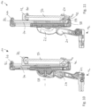
- FIG. 10 A vertical section of the mounting system according to FIG. 7 along a section line marked X-X in FIG. 8 ;
- FIG. 11 A vertical section of the mounting system according to FIG. 7 along a section line marked XI-XI in FIG. 8 ;
- FIG. 12 An illustration corresponding to FIG. 7 with an arrangement of a comparatively larger electronic device.
- a mounting system shown in the drawing is designated in its entirety by reference sign 10 . It comprises a connecting section 12 in the form of a plug-in part 14 , which can be detachably fixed in a receiving socket 16 , in particular in a latching manner.
- receiving socket 16 is part of a motor vehicle seat assembly and is arranged, for example, in the region of a backrest of a motor vehicle seat. For the connection between plug-in part 14 and receiving socket 16 , it is sufficient to insert plug-in part 14 into receiving socket 16 according to an insertion direction 18 and to latch it there.
- Mounting system 10 has at least one intermediate section 20 , 22 , wherein a first connecting section 20 is pivotable relative to plug-in part 14 about a first pivot axis 24 and is connected in an articulated manner to second intermediate section 22 via a second pivot axis 26 .
- Second intermediate section 22 defines an axis of rotation 28 for a first holder 30 rotatably mounted on second intermediate section 22 ; compare in particular FIGS. 1 , 3 and 4 .
- pivot axes 24 and 26 and pivot axis 28 run substantially horizontally, wherein pivot axes 24 and 26 typically extend in a transverse direction of the vehicle and pivot axis 28 extend in a longitudinal direction of the vehicle.
- Second holder 30 has a base part 32 and a cover part 34 , the gap between which can be modified; compare FIGS. 1 and 6 .
- cover part 34 is guided on base part 32 by means of a linear guide known per se.
- Base part 32 and cover part 34 can be latched relative to one another and optionally preloaded in directions facing each other by means of a spring 36 ; compare FIG. 5 .
- Base part 32 has a rear section 38 and a foot section 40 on which a first holding section 42 is formed; compare FIG. 1 .
- Cover part 34 has a head section 44 having an additional first holding section 46 .
- a first holding space 48 of first holder 30 is delimited between foot section 40 and head section 44 .
- Such first holding space 48 is used, for example, for an arrangement of a first electronic device 50 , which is indicated schematically in FIG. 1 by a rectangular outline and is formed, for example, as a tablet computer.
- a second holder 52 can be arranged in first holding space 48 and can have a second holding space 54 for holding a second electronic device 56 .
- Second holder 52 has an edge section 58 that serves for an arrangement in a first holding section 42 of first holder 30 , thus it is receivable therein in place of an edge section of a first electronic device 50 .
- Second holder 52 further has a second holding section 60 for mounting a boundary edge 62 of second electronic device 56 .
- Second holding section 60 and edge section 58 are spaced apart from one another and are immovable relative to one another.
- Edge section 58 and second holding section 60 are arranged on a lower part of second holder 52 , which is designated in its entirety by reference sign 64 , wherein an upper part 66 of second holder 52 is movable relative to lower part 64 , such that a gap of upper part 66 from lower part 64 is adjustable; compare FIGS. 1 and 6 .
- Lower part 64 has a first material section 68 for forming edge section 58 and for spacing second holding section 60 from edge section 58 .
- Lower part 64 further has a second material section 70 for supporting upper part 66 .
- Upper part 66 has an additional second holding section 72 that covers, but does not overlap, a boundary edge 74 of second electronic device 56 .
- Lower part 64 and upper part 66 are preloaded in directions opposite to and away from one another, such that second holding sections 60 and 72 of second holder 52 strive to assume a maximum gap relative to one another. In this manner, it is ensured that second holder 52 is preloaded in first holding space 48 of first holder 30 .
- a first holding section, in this case (upper) first holding section 46 , of first holder 30 performs part of the holding function for second electronic device 56 , which is clasped in a positive-locking manner by both (upper) first holding section 46 and second holding section 60 of second holder 52 .
- frictional locking elements 74 , 76 may be provided, which may be in the form of tabs and may work together with a rear side of electronic device 56 facing first holder 30 ; compare FIGS. 4 and 5 (shown in a relaxed resting state in FIG. 5 ). Adjacent to boundary edges 62 and 74 of electronic device 56 , further positive-locking or frictional locking elements 78 , 80 may be arranged, compare FIGS. 1 and 4 , for example in the form of elastomer lips or rails.
- first holding space 48 of first holder 30 is not occupied. Based on this state, either a first electronic device 50 can be arranged in first holding space 48 , wherein a gap between base section 32 and base section 34 is to be selected such that electronic device 50 is insertable into first holding space 48 . By moving cover part 34 in the direction of base part 32 , first electronic device 50 can then be fixed in place, wherein first holding sections 42 and 46 clasp first electronic device 50 .
- only second holder 52 can initially be arranged in first receiving space 48 .
- upper part 66 is moved such that upper part 66 is at a greater distance from lower part 64 and such that upper part 66 with its second holding section 72 comes into engagement with (upper) first holding section 46 of first holder 30 .
- second electronic device 56 can initially be brought into the engagement region of (lower) second holding section 60 with lower boundary edge 62 , and can then be brought into the engagement region of (upper) first holding section 46 with upper boundary edge 74 from a region outside (upper) first holding section 46 by pressing second electronic device 56 with its upper boundary edge 74 against the outside of (upper) first holding section 46 .
- cover part 34 deflects upwardly against the action of spring 36 ;
- second electronic device 56 completely enters first receiving space 54 of second holder 52 , and subsequently cover part 34 moves back in the direction of base part 32 due to the action of spring 36 .
- second electronic device 56 is fixed to second holder 52 , while second holder 52 is in turn fixed to first holder 30 .
- one of the first holding sections of first holder 30 performs a holding function for second electronic device 56 .
- a holding function at upper boundary edge 74 of second electronic device 56 is realized by a second holding section 72 of second holder 52 , which is provided independently of (upper) first holding section 46 of first holder 30 .
- FIGS. 7 to 12 For the structure and operation of mounting system 10 according to FIGS. 7 to 12 , reference is made to the preceding description of FIGS. 1 to 6 ; the special features of the mounting system 10 according to FIGS. 7 to 12 are discussed below.
- First material section 68 of lower part 64 of second holder 52 has only a small overall height; in contrast, second material section 70 of lower part 64 has a length that is greater than a maximum height of electronic device 56 .
- Second material section 70 extends to a stop 82 ; compare FIG. 7 .
- Stop 82 is received in (upper) first holding section 46 of first holder 30 .
- the gap between edge section 58 and stop 82 can be modified.
- First holding section 46 is spring-mounted in a movable/articulated manner on cover part 34 .
- a guide 84 is provided on second material section 70 of second holder 52 for (upper) second holding section 72 of second holder 72 .
- Two second holding sections 60 and 62 are preloaded in the direction of one another, such that two second holding sections 60 and 72 strive to occupy the smallest possible gap relative to one another.
- first electronic device 50 (compare FIG. 1 ) can be arranged in first holding space 48 .
- first holding space 48 can be arranged in first holding space 48 .
- edge section 48 of second holder 52 is brought into engagement with (lower) first holding section 42 of first holder 30 , wherein stop 82 is initially still out of engagement with (upper) first holding section 46 of first holder 30 .
- (upper) first holding section 46 springs out, such that stop 82 can be arranged in the clasping region of (upper) first holding section 46 and is fixed there, wherein the gap between base part 32 and cover part 34 of first holder 30 depends exclusively on the size of second holder 52 and not on the size or height of a second electronic device 56 to be held; compare FIGS. 7 and 12 .
- second electronic device 56 can initially be brought with its upper boundary edge 54 into engagement with (upper) second holding section 72 , in order to displace the latter together with second electronic device 56 in the direction of (upper) first holding section 46 of first holder 30 until lower boundary edge 62 of second electronic device 56 can be inserted into the effective range of (lower) second holding section 60 .
- the subsequent fixing of second electronic device 56 takes place by means of spring force, which urges (upper) second holding section 72 in the direction of (lower) second holding section 60 .
- second electronic device 56 For removal of second electronic device 56 , second electronic device 56 can be moved upwardly together with (upper) second holding section 72 until lower boundary edge 72 becomes disengaged from (lower) second holding section 60 and second electronic device 56 can be removed from second holding space 54 of first holder 52 .
Landscapes
- Engineering & Computer Science (AREA)
- Mechanical Engineering (AREA)
- Fittings On The Vehicle Exterior For Carrying Loads, And Devices For Holding Or Mounting Articles (AREA)
- Casings For Electric Apparatus (AREA)
- Motor Or Generator Frames (AREA)
- Connection Of Motors, Electrical Generators, Mechanical Devices, And The Like (AREA)
Abstract
Description
Claims (20)
Applications Claiming Priority (2)
| Application Number | Priority Date | Filing Date | Title |
|---|---|---|---|
| DE202021104338.5 | 2021-08-13 | ||
| DE202021104338.5U DE202021104338U1 (en) | 2021-08-13 | 2021-08-13 | Fastening system for the detachable fastening of electronic devices in a motor vehicle |
Publications (2)
| Publication Number | Publication Date |
|---|---|
| US20230050234A1 US20230050234A1 (en) | 2023-02-16 |
| US12083965B2 true US12083965B2 (en) | 2024-09-10 |
Family
ID=82846595
Family Applications (1)
| Application Number | Title | Priority Date | Filing Date |
|---|---|---|---|
| US17/886,780 Active 2043-02-09 US12083965B2 (en) | 2021-08-13 | 2022-08-12 | Mounting system for detachably mounting electronic devices in a motor vehicle |
Country Status (5)
| Country | Link |
|---|---|
| US (1) | US12083965B2 (en) |
| EP (1) | EP4137365B1 (en) |
| CN (1) | CN115703408A (en) |
| DE (1) | DE202021104338U1 (en) |
| ES (1) | ES3033150T3 (en) |
Families Citing this family (2)
| Publication number | Priority date | Publication date | Assignee | Title |
|---|---|---|---|---|
| DE202021102428U1 (en) * | 2021-05-05 | 2021-05-14 | Kinetix Ag | Holder for releasable attachment of a flat device to a motor vehicle seat |
| USD1009133S1 (en) * | 2021-08-05 | 2023-12-26 | Shenzhen Yuansu Chuangda Technology Co., Ltd | Selfie stick stabilizer |
Citations (6)
| Publication number | Priority date | Publication date | Assignee | Title |
|---|---|---|---|---|
| WO2003002376A1 (en) | 2001-06-28 | 2003-01-09 | Gisela Bisplinghoff | Adapter for a telephone holder pertaining to a hands-free device |
| US20110121148A1 (en) * | 2009-11-24 | 2011-05-26 | Patrick Pernia | Apparatus and method for holding a portable electronic device |
| US20140138419A1 (en) | 2012-11-20 | 2014-05-22 | Kenu Inc. | Adjustable portable device holder |
| US20150329062A1 (en) * | 2012-11-05 | 2015-11-19 | Kinetix Ag | Device for retaining flat, approximately rectangular appliances such as tablet computers or mobile telephones in the interior of a motor vehicle |
| DE202015107110U1 (en) | 2015-12-28 | 2016-04-21 | Faurecia Interieur Industrie | Carrier device for smartphone |
| DE112014005009B4 (en) | 2013-10-30 | 2022-03-17 | Faurecia Interieur Industrie | Height-adjustable holder for a mobile device |
-
2021
- 2021-08-13 DE DE202021104338.5U patent/DE202021104338U1/en active Active
-
2022
- 2022-08-05 ES ES22189019T patent/ES3033150T3/en active Active
- 2022-08-05 EP EP22189019.7A patent/EP4137365B1/en active Active
- 2022-08-12 CN CN202210969027.6A patent/CN115703408A/en active Pending
- 2022-08-12 US US17/886,780 patent/US12083965B2/en active Active
Patent Citations (6)
| Publication number | Priority date | Publication date | Assignee | Title |
|---|---|---|---|---|
| WO2003002376A1 (en) | 2001-06-28 | 2003-01-09 | Gisela Bisplinghoff | Adapter for a telephone holder pertaining to a hands-free device |
| US20110121148A1 (en) * | 2009-11-24 | 2011-05-26 | Patrick Pernia | Apparatus and method for holding a portable electronic device |
| US20150329062A1 (en) * | 2012-11-05 | 2015-11-19 | Kinetix Ag | Device for retaining flat, approximately rectangular appliances such as tablet computers or mobile telephones in the interior of a motor vehicle |
| US20140138419A1 (en) | 2012-11-20 | 2014-05-22 | Kenu Inc. | Adjustable portable device holder |
| DE112014005009B4 (en) | 2013-10-30 | 2022-03-17 | Faurecia Interieur Industrie | Height-adjustable holder for a mobile device |
| DE202015107110U1 (en) | 2015-12-28 | 2016-04-21 | Faurecia Interieur Industrie | Carrier device for smartphone |
Non-Patent Citations (3)
| Title |
|---|
| European Office Communication dated Jan. 19, 2023. |
| German Search Report dated May 5, 2022. |
| National Products; "Catalogue National Products Inc.," Jan. 2020; XP55818576A, pp. 1-32. |
Also Published As
| Publication number | Publication date |
|---|---|
| ES3033150T3 (en) | 2025-07-31 |
| DE202021104338U1 (en) | 2022-11-15 |
| EP4137365B1 (en) | 2025-06-04 |
| CN115703408A (en) | 2023-02-17 |
| US20230050234A1 (en) | 2023-02-16 |
| EP4137365A1 (en) | 2023-02-22 |
Similar Documents
| Publication | Publication Date | Title |
|---|---|---|
| US12083965B2 (en) | Mounting system for detachably mounting electronic devices in a motor vehicle | |
| US6848925B2 (en) | Connector assembly, connector, connector assembling construction and method of assembling them | |
| US5815377A (en) | Apparatus for auto docking PCI cards | |
| US6288911B1 (en) | Hot plug solution and adjustable retention bracket | |
| US3915493A (en) | Seat cushion retainer device | |
| US11025762B2 (en) | Holder for flat, approximately rectangular devices, such as tablet computers or smartphones | |
| EP1093959B1 (en) | Electric connection method and structure between seat and body | |
| US4472606A (en) | Mobile radio-telephone handset and holder | |
| KR102746682B1 (en) | Brush module and its mounting method | |
| US6874854B2 (en) | Headrest device for a vehicle seat, and a vehicle seat including such a device | |
| KR20070066845A (en) | Door module positioning system | |
| TWI548369B (en) | Mounting part for slide rail assembly | |
| US20050279902A1 (en) | Object holder with adjustable engagement jaws | |
| CN105557080A (en) | Fan device | |
| KR102347750B1 (en) | Sunvisor of vehicles | |
| EP1241761A1 (en) | Electrical wiring harness guiding and retaining device | |
| KR20190116055A (en) | Connector having a structure of terminal pushing | |
| US4668036A (en) | Large picture display device | |
| CN214751697U (en) | Hard disk mounts and electronic equipment | |
| US6767244B2 (en) | Connector construction and a method for connecting a pair of connectors | |
| JP4414019B2 (en) | Wiring duct cover detachment prevention device | |
| CN112839547B (en) | Fixing device for the front of the drawer on the frame | |
| CN210822078U (en) | Horizontal fixing base of vehicle-mounted support and vehicle-mounted support | |
| US6254419B1 (en) | Electrical connector | |
| CN114537289A (en) | Holding device, center console and motor vehicle |
Legal Events
| Date | Code | Title | Description |
|---|---|---|---|
| FEPP | Fee payment procedure |
Free format text: ENTITY STATUS SET TO UNDISCOUNTED (ORIGINAL EVENT CODE: BIG.); ENTITY STATUS OF PATENT OWNER: SMALL ENTITY |
|
| FEPP | Fee payment procedure |
Free format text: ENTITY STATUS SET TO SMALL (ORIGINAL EVENT CODE: SMAL); ENTITY STATUS OF PATENT OWNER: SMALL ENTITY |
|
| AS | Assignment |
Owner name: AG, KINETIX, SWITZERLAND Free format text: ASSIGNMENT OF ASSIGNORS INTEREST;ASSIGNORS:SPANG, PETER;HEIDINGER, JUERGEN;FISCHER, WOLFGANG;AND OTHERS;SIGNING DATES FROM 20220701 TO 20220830;REEL/FRAME:061012/0397 |
|
| STPP | Information on status: patent application and granting procedure in general |
Free format text: DOCKETED NEW CASE - READY FOR EXAMINATION |
|
| STPP | Information on status: patent application and granting procedure in general |
Free format text: NOTICE OF ALLOWANCE MAILED -- APPLICATION RECEIVED IN OFFICE OF PUBLICATIONS |
|
| STPP | Information on status: patent application and granting procedure in general |
Free format text: AWAITING TC RESP., ISSUE FEE NOT PAID |
|
| STPP | Information on status: patent application and granting procedure in general |
Free format text: NOTICE OF ALLOWANCE MAILED -- APPLICATION RECEIVED IN OFFICE OF PUBLICATIONS |
|
| STPP | Information on status: patent application and granting procedure in general |
Free format text: NOTICE OF ALLOWANCE MAILED -- APPLICATION RECEIVED IN OFFICE OF PUBLICATIONS |
|
| STPP | Information on status: patent application and granting procedure in general |
Free format text: PUBLICATIONS -- ISSUE FEE PAYMENT RECEIVED |
|
| STPP | Information on status: patent application and granting procedure in general |
Free format text: PUBLICATIONS -- ISSUE FEE PAYMENT VERIFIED |
|
| STCF | Information on status: patent grant |
Free format text: PATENTED CASE |