US12081168B2 - Electrical pathway intermittent fault detection - Google Patents
Electrical pathway intermittent fault detection Download PDFInfo
- Publication number
- US12081168B2 US12081168B2 US17/824,324 US202217824324A US12081168B2 US 12081168 B2 US12081168 B2 US 12081168B2 US 202217824324 A US202217824324 A US 202217824324A US 12081168 B2 US12081168 B2 US 12081168B2
- Authority
- US
- United States
- Prior art keywords
- voltage
- frequency
- electrical
- photovoltaic
- workpiece
- Prior art date
- Legal status (The legal status is an assumption and is not a legal conclusion. Google has not performed a legal analysis and makes no representation as to the accuracy of the status listed.)
- Active, expires
Links
Images


Classifications
-
- H—ELECTRICITY
- H02—GENERATION; CONVERSION OR DISTRIBUTION OF ELECTRIC POWER
- H02S—GENERATION OF ELECTRIC POWER BY CONVERSION OF INFRARED RADIATION, VISIBLE LIGHT OR ULTRAVIOLET LIGHT, e.g. USING PHOTOVOLTAIC [PV] MODULES
- H02S50/00—Monitoring or testing of PV systems, e.g. load balancing or fault identification
- H02S50/10—Testing of PV devices, e.g. of PV modules or single PV cells
-
- G—PHYSICS
- G01—MEASURING; TESTING
- G01R—MEASURING ELECTRIC VARIABLES; MEASURING MAGNETIC VARIABLES
- G01R31/00—Arrangements for testing electric properties; Arrangements for locating electric faults; Arrangements for electrical testing characterised by what is being tested not provided for elsewhere
- G01R31/08—Locating faults in cables, transmission lines, or networks
- G01R31/081—Locating faults in cables, transmission lines, or networks according to type of conductors
- G01R31/086—Locating faults in cables, transmission lines, or networks according to type of conductors in power transmission or distribution networks, i.e. with interconnected conductors
-
- G—PHYSICS
- G01—MEASURING; TESTING
- G01R—MEASURING ELECTRIC VARIABLES; MEASURING MAGNETIC VARIABLES
- G01R31/00—Arrangements for testing electric properties; Arrangements for locating electric faults; Arrangements for electrical testing characterised by what is being tested not provided for elsewhere
- G01R31/08—Locating faults in cables, transmission lines, or networks
- G01R31/11—Locating faults in cables, transmission lines, or networks using pulse reflection methods
-
- H—ELECTRICITY
- H02—GENERATION; CONVERSION OR DISTRIBUTION OF ELECTRIC POWER
- H02S—GENERATION OF ELECTRIC POWER BY CONVERSION OF INFRARED RADIATION, VISIBLE LIGHT OR ULTRAVIOLET LIGHT, e.g. USING PHOTOVOLTAIC [PV] MODULES
- H02S40/00—Components or accessories in combination with PV modules, not provided for in groups H02S10/00 - H02S30/00
- H02S40/30—Electrical components
- H02S40/34—Electrical components comprising specially adapted electrical connection means to be structurally associated with the PV module, e.g. junction boxes
-
- H—ELECTRICITY
- H02—GENERATION; CONVERSION OR DISTRIBUTION OF ELECTRIC POWER
- H02S—GENERATION OF ELECTRIC POWER BY CONVERSION OF INFRARED RADIATION, VISIBLE LIGHT OR ULTRAVIOLET LIGHT, e.g. USING PHOTOVOLTAIC [PV] MODULES
- H02S50/00—Monitoring or testing of PV systems, e.g. load balancing or fault identification
- H02S50/10—Testing of PV devices, e.g. of PV modules or single PV cells
- H02S50/15—Testing of PV devices, e.g. of PV modules or single PV cells using optical means, e.g. using electroluminescence
-
- Y—GENERAL TAGGING OF NEW TECHNOLOGICAL DEVELOPMENTS; GENERAL TAGGING OF CROSS-SECTIONAL TECHNOLOGIES SPANNING OVER SEVERAL SECTIONS OF THE IPC; TECHNICAL SUBJECTS COVERED BY FORMER USPC CROSS-REFERENCE ART COLLECTIONS [XRACs] AND DIGESTS
- Y02—TECHNOLOGIES OR APPLICATIONS FOR MITIGATION OR ADAPTATION AGAINST CLIMATE CHANGE
- Y02E—REDUCTION OF GREENHOUSE GAS [GHG] EMISSIONS, RELATED TO ENERGY GENERATION, TRANSMISSION OR DISTRIBUTION
- Y02E10/00—Energy generation through renewable energy sources
- Y02E10/50—Photovoltaic [PV] energy
Definitions
- PV cells Photovoltaic (PV) cells, commonly known as solar cells, are devices for conversion of solar radiation into electrical energy.
- solar radiation impinging on the surface of, and entering into, the substrate of a solar cell creates electron and hole pairs in the bulk of the substrate.
- the electron and hole pairs migrate to p-doped and n-doped regions in the substrate, thereby creating a voltage differential between the doped regions.
- the doped regions are connected to the conductive regions on the solar cell to direct an electrical current from the cell to an external circuit.
- PV cells are combined in an array such as a PV module, the electrical energy collected from all of the PV cells can be combined in series and parallel arrangements to provide power with a certain voltage and current.
- PV module Numerous electrical pathways exist in a PV module. These pathways include: electrical components themselves—including their internal sub-components—leads emanating from electrical components; system traces; system busses; and connections therebetween. System, component, and sub-component connections may be soldered connections or connections without solder, such as snap-fit mechanical connections. When any of these pathways fail, the PV module operation and output may be hindered or completely lost depending upon the number and/or severity of the pathway failure. These failures may be permanent failures or intermittent failures. Intermittent pathway failures may be considered electrical pathways that are operational during periods of time and unintentionally inoperable during other periods of time.
- FIG. 1 illustrates a schematic of a laminate photovoltaic workpiece under forward bias testing according to some embodiments.
- FIG. 2 illustrates a schematic of a laminate photovoltaic workpiece under reverse bias testing according to some embodiments.
- FIG. 3 illustrates process elements for workpiece testing as may be employed in some embodiments.
- FIG. 4 illustrates process elements for time domain reflectometry (TDR) workpiece testing as may be employed in some embodiments.
- FIG. 5 illustrates process elements for non-illumination current/voltage (dark IV) workpiece testing as may be employed in some embodiments.
- FIG. 6 illustrates process elements for infra-red workpiece testing as may be employed in some embodiments.
- FIG. 7 illustrates process elements for mechanical agitation workpiece testing as may be employed in some embodiments.
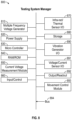
- FIG. 8 illustrates an exemplary testing system manager according to some embodiments.
- FIG. 9 illustrates a schematic of a laminate photovoltaic workpiece as may be employed in some embodiments.
- first “First,” “Second,” etc. As used herein, these terms are used as labels for nouns that they precede, and do not imply any type of ordering (e.g., spatial, temporal, logical, etc.).
- reference to a “first” mechanical vibration test does not necessarily imply that this mechanical vibration test is the first test in a sequence; instead the term “first” is used to differentiate this mechanical vibration test from another mechanical vibration test (e.g., a “second” mechanical vibration test).
- this term is used to describe one or more factors that affect a determination. This term does not foreclose additional factors that may affect a determination. That is, a determination may be solely based on those factors or based, at least in part, on those factors.
- a determination may be solely based on those factors or based, at least in part, on those factors.
- Coupled means that one element/node/feature is directly or indirectly joined to (or directly or indirectly communicates with) another element/node/feature, and not necessarily mechanically.
- inhibit is used to describe a reducing or minimizing effect. When a component or feature is described as inhibiting an action, motion, or condition it may completely prevent the result or outcome or future state completely. Additionally, “inhibit” can also refer to a reduction or lessening of the outcome, performance, and/or effect which might otherwise occur. Accordingly, when a component, element, or feature is referred to as inhibiting a result or state, it need not completely prevent or eliminate the result or state.
- Embodiments may include an end of line electrical pathway testing system that uses a monitoring current with rapid voltage sensing frequencies to measure interconnections between photovoltaic cell circuits, laminated solar modules or other workpieces, for intermittent electrical pathways such as solder connections and diode functionality. Testing in embodiments may occur on partially assembled as well as fully assembled workpieces. In other words, electrical workpiece connections may be tested even though still more electrical connections remain to be added—a fully assembled workpiece, with each of its intended connections may also be tested. For example, a grouping of cells of a photovoltaic laminate may be tested before final assembly of the photovoltaic laminate as well as after final assembly of the photovoltaic laminate.
- the connections between photovoltaic cells, rather than connections within the cells themselves, are preferably targets for the intermittent testing of embodiments.
- TDR Time Domain Reflectometry
- mechanical agitation mechanical agitation
- dark current/voltage testing dark IV
- thermographic imaging e.g., infra-red thermal imaging.
- TDR Time Domain Reflectometry
- thermographic imaging e.g., infra-red thermal imaging.
- These methodologies may be applied individually as well as in various combinations, and may be applied in various orders.
- These methodologies may be applied under forward bias electrical loading conditions of the workpiece as well as reverse-bias electrical loading conditions of the workpiece. Reversing the electrical loading on a workpiece from test to test or within testing methodologies may allow for testing or otherwise isolating electrical connections of a workpiece for testing not otherwise testable as well as for determining which, if any, electrical connections have failed.
- a photovoltaic laminate with diodes may contain one-way electrical pathways that only become active under shaded conditions, these one-way pathways may not be activated in each testing condition and thereby testable unless current is applied in a forward bias during testing or a reverse bias during testing.
- testing in embodiments may first be conducted with current flowing in one direction and, tested again, with current reversed.
- laminates or modules being tested may be run both in reverse bias to measure diode function and solder joint condition in junction boxes. Then, a test may be run in the forward current bias direction to test for missing or broken solder connections on a center lane to bus ribbon joint, for example, as well as other electrical pathways.
- a testing system or process in embodiments may use Time Domain Reflectometry (TDR) to test electrical connections and to isolate the location of failed or passing electrical connections.
- TDR Time Domain Reflectometry
- varying electrical signals may be placed on a workpiece and subsequently measured for the resulting reflected signals experienced after passing though or otherwise interfacing with one or more connections.
- the resulting signals are considered to result from the high damping effects introduced by passing by or through solar cells and other diodes.
- the resulting dampened, reflected signals may be measured and used to determine if any electrical connections in the workpiece have failed and which ones have failed.
- Processes in embodiments may measure electrical signals reflected back from a connection to be tested much like sending an acoustic signal underwater and listening for the reflected signal.
- Processes in embodiments may employ activated diodes, which have been turned on or otherwise biased with a power supply.
- diodes to be tested may receive an applied voltage or current from a power supply so as to amplify the reflected signal during TDR testing.
- Embodiments may also apply different electrical frequencies over a spectrum of frequencies when testing. This spread spectrum TDR testing may serve to promote testing accuracy by providing testing at numerous testing frequencies. This spread spectrum may, accordingly, provide to increase the ability to determine reflected signals as well as to test electrical connections that may provide indicia of failure at one testing frequency but not another frequency. Whether the reflected signal or downstream signal is collected, embodiments may employ these signals to determine whether a workpiece contains functioning or impaired electrical connections.
- a testing system or process in embodiments may use a percussive agitation from a vibration generator to stimulate a change in electrical signal during the presence of an intermittent connection being tested for.
- Exemplary agitation tests may be performed with forward and reverse currents in order to test one-way electrical pathways in a workpiece being tested.
- a photovoltaic laminate with diodes may contain one-way electrical pathways that only become active under shaded conditions, these one-way pathways may not be activated and thereby testable unless current is applied in a forward bias during testing or a reverse bias during testing.
- percussive agitation testing may first be conducted with current flowing in one direction and, tested again, or a third or fourth time, with current reversed.
- a testing system or process in embodiments may employ dark current/voltage testing, (dark IV or non-illuminated IV).
- This dark IV applied electricity may, too, be applied in a forward bias as well as in a reverse bias of the workpiece.
- non-illumination applied current and voltage testing may be conducted with both forward bias current and reverse bias current.
- resistance changes, current changes, or other measurable electrical properties may be measured to determine electrical connection faults and failures.
- open joints may be more readily determined by forward bias testing while reverse bias testing may be more suitable for determining intermittent or partially complete electrical connections.
- hardware used for flash testing PV modules may also be employed to sense and measure resulting resistances from dark IV testing of embodiments.
- a testing system or process in embodiments may employ infra-red imaging or other thermal imaging.
- a current may be applied to a workpiece in forward and/or reverse bias while the workpiece is viewed using infra-red camera(s) or other thermographic sensors.
- the presence and/or absence or quantity of heat signatures may be used to identify faulty electrical connections.
- the current may be applied for fractions of a second as well as one, two, five, ten or more seconds.
- the applied current may be fractions of an amp as well as one, two, five, ten, I max , or more amps.
- a fraction of max current of a workpiece or max current of a subsection of workpiece, as well as max current itself, and even a multiple of max current, may each be employed in embodiments when testing using infra-red sensors or other thermography sensors. Lock-in thermography techniques may be employed as well.
- thermography when identifying module level electrical connections, for example, current may be sent in a forward bias direction for a period of time, e.g., five seconds, and then a reverse bias direction for a period of time, e.g., five seconds.
- An infra-red sensor or other thermography sensor may then read the infra-red or other thermal signatures of the electrical connections in the module workpiece and report on whether any connection is faulty and if so which ones.
- the electrical connections being tested may be within potting material, such as potting in a junction box.
- Embodiments may be employed to identify intermittent connections or other faults in connections made during assembly of subcomponents of a workpiece.
- internals of PV cells may not be tested in embodiments using thermography. Rather, j-boxes, connections of groupings of PV cells to a bus, etc., may be tested using the thermographic or other techniques taught herein.
- Thermographic testing such as infra-red testing, may be employed to take advantage of low resistance shunts or other known connection properties. These low resistance areas can have higher currents, and corresponding higher thermal outputs. By using forward and reverse bias currents, more interconnections can be cordoned and tested with thermography or other techniques of embodiments.
- a testing system manager may observe the infra-red signatures, other thermal signatures, or other testing methodology outcomes (TDR, Dark IV, mechanical observation) and use them to determine operational status of one or more electrical connections in the workpiece.
- TDR Thermal observations
- resistance measurements resistance measurements
- inductance measurements in both real-time as well as from stored data.
- These observations may be compared to known benchmarks to determines if a junction being tested meets or does not meet an expected performance standard. For example, an expected temperature rating or an expected resistance or an expected impedance may be compared to one or more outputs from conducted testing.
- measurements may be taken with and without percussive agitation or other testing methodology. Measurements taken without percussive agitation or other testing methodology may be taken to provide baseline or target voltage readings for properly operational workpieces. These target values may then be used for comparison purposes to determine whether a workpiece being tested meets these target values or shows an intermittent pathway of some kind using one or more of the testing techniques taught herein.
- the topology of the workpiece may be considered and used to determine the type of intermittent failure. For example, certain electrical pathways may be selectively used in PV modules. When only a reverse bias test provides a failure, the selectively used pathways may be indicated. If a diode or junction box is part of the selectively used pathway, reworking the connections therein may be employed to fix or otherwise salvage the workpiece.
- System embodiments may include a power supply, a mobile agitation device, a thermographic sensor, and a voltage measurement system. These may be integrated into an end of line tester in a solar module factory to carry out intermittent connection and diode tests after flash testing and electro luminescence (EL) tests have completed.
- a power supply may be applied in a reverse bias on the module or other workpiece, and a voltage may be measured.
- the power supply may also be employed for dark IV testing and TDR testing.
- the module or other workpiece may then be agitated using a haptic feedback device or other mechanical vibration source and the voltage may be measured again—sampled rapidly enough to identify any circuit opening conditions due to the vibration of the module.
- a voltage of the module at ⁇ 100 mA in reverse may be approximately 2.5V. If this value is much lower or higher than 2.5V then a failure of diodes may be presumed and if the voltage changes significantly upon addition of the vibrating motion then it may be concluded that one of the j-box solder joints is intermittent. A forward bias of around 100 mA may also be applied in embodiments.
- the voltage may be measured and a vibration may be applied to the module (by touching the frame with a haptic feedback device or other vibration source). If the voltage changes significantly upon agitation a center lane to bus ribbon solder joint or another electrical pathway may be considered intermittent.
- Embodiments may be calibrated to test various electrical pathways, including solder joints and mechanical connections. This testing may be performed on one or more PV laminates and/or PV modules, or other workpiece, which may be large and have circuits embedded between glass layers. When a failure is found, the indicator may specify a portion or component of the PV laminate in certain embodiments or may fail an entire PV laminate in other embodiments. Thus, embodiments may provide end of line module testing to identify intermittent connections and may also provide a diode screen that may screen 100% or about 100% or other portion of the diodes.
- forward bias loading may be employed in the same direction as Electro Luminescence (EL) testing but with a smaller current.
- EL Electro Luminescence
- measurements may be taken before agitation as a benchmark, and after agitation to sense an intermittent connection.
- the sensing should have a sampling rate that allows multiple samples to be taken during each agitation cycle or electrical cycle.
- the power source for the EL test may also be employed to power the mechanical agitation testing.
- the frequencies of agitation may range from tens of cycles per minute to thousands of cycles per second, or more or less.
- the voltages employed may range from micro volts to tens of volts or more or less.
- the number of testing stations on a manufacturing line may be reduced when automatic soldering is used and testing may be conducted immediately after soldering is conducted.
- Embodiments may provide for testing PV laminates before or after potting is injected. Other components, such as frames and junction boxes may already be installed when testing is conducted.
- embodiments may employ rapid voltage sensing.
- This sensing may include use of a constant current applied to a workpiece and detecting voltages before and after agitation is mechanically applied.
- a voltage signal change occurs and should be sampled at a rate faster than the agitation frequency. For example, if agitation was applied at 19 Hz then sampling may be taken at 190 Hz or some other sampling rate larger than 19 Hz.
- a sampling rate of 10 ⁇ the agitation frequency may be used as a starting point for measuring voltage or current fluctuation frequency waveforms although other multipliers, such as 2 ⁇ , 3 ⁇ , 4 ⁇ , 5 ⁇ , 6 ⁇ , 15 ⁇ , 20 ⁇ , etc., may also be used.
- Embodiments may employ a movable control arm such that an electrical pathway tester may be moved to touch the PV circuit, laminate module or other workpiece being tested.
- the movement of the control arm may be automated, semi-automated, and manually controlled.
- the electrical pathway tester may comprise an exposed direct contact vibration generator, a thermographic sensor, an infra-red sensor, a multiple frequency voltage generator, and/or other testing apparatus.
- the sensors of embodiments may sense variations in voltage on the order of a few millivolts when a circuit is intact and an open circuit, e.g., 60 v, when a connection is intermittent.
- Sensed voltages, of tens or hundreds of millivolts may also indicate an intermittent circuit.
- These millivolt or larger variations may be indicated visually, through a screen or readout, or audibly through a speaker.
- a distorted audio signal can indicate an intermittent connection or otherwise failed workpiece.
- processes may include testing with forward and reverse currents.
- the forward sweeps i.e., testing with current in a first diode direction, may include measuring voltage to create a baseline.
- This baseline voltage may be an alternating voltage as well as a stable voltage.
- the workpiece being tested e.g., a PV laminate
- the workpiece being tested e.g., a PV laminate
- Measurements of the resulting voltage signal may then be taken at a frequency higher than a baseline testing frequency. This sampling may occur ten times or more in order to sample resulting voltages after agitation. When sufficient changes in voltage are detected, an intermittent connection may be considered to have been identified.
- the difference between the sampled voltages and the expected voltages may be on the order of 15%, 20%, 25%, etc. or more or less. This percentage detected difference may depend on the workpiece being tested, the test current being applied, and the frequency of the agitation, dark IV testing, TDR, and/or sampling.
- a reverse sweep may also be conducted.
- This reverse sweep may provide current flowing in the opposite direction, i.e., opposite the first diode direction.
- the testing may be conducted in the same fashion but may indicate that a different portion of the workpiece has an intermittent connection when a failure is detected.
- different portions of the workpiece which may not be accessible under the first current flow due to diodes or other circuit topologies, may be tested in a reverse current situation.
- by conducting testing with both forward bias and reverse bias portions of the workpiece, e.g., the PV laminate may be identified as failing.
- junction box connections not accessible under a forward bias test may be identified with a reverse bias test.
- a center bus solder joint problem can be confirmed using forward and reverse bias flows when the topology of a center bus provides for different current flows under the forward and reverse current bias flows.
- Embodiments may provide an electrical pathway intermittent fault detection system comprising an electrical pathway tester having at least one of an exposed direct-contact vibration generator, a thermal sensor; or a multiple-frequency voltage generator; an exposed electrical sensor; an electrical power supply; and a microcontroller.
- the microcontroller may be configured, using outputs from the electrical pathway tester, to determine whether an intermittent electrical pathway is present in a potted junction-box of the photovoltaic laminate and to provide a signal when an intermittent electrical pathway is detected.
- the vibration generator may be configured to generate vibrations across a range of frequencies, and the power supply may be configured to provide electrical power to the vibration generator.
- the microcontroller may be configured to consider the present frequency of vibration of the vibration generator when the vibration generator is in contact with a photovoltaic laminate, and further configured to consider voltages sampled from the photovoltaic laminate when the vibration generator is in contact with the photovoltaic laminate, the sampling rate of considered voltages being faster than the present frequency of vibration. In some embodiments, the microcontroller may be further configured to compare the voltages sampled with target voltages, to determine whether an intermittent electrical pathway is present in the photovoltaic laminate and to provide a signal when an intermittent electrical pathway is detected.
- Embodiments may sometimes comprise a shared bus, the shared bus coupled to two or more of: the vibration generator, the voltage sensor, the power supply, and the microcontroller.
- a preset frequency of vibration may be set to one-tenth or less of the frequency of the sampling rate of considered voltages and in some embodiments the target voltage is predetermined, calibrated for the photovoltaic laminate, and is in a range of 0.002 volts to 20 volts.
- the voltages sampled from the photovoltaic laminate result first from a forward bias current and from a reverse bias current, the current provided by the power supply, the forward bias current used to detect soldering failure in the photovoltaic laminate, the reverse bias current used to detect diode failure in the photovoltaic laminate.
- the signal when an intermittent electrical pathway is detected, may be an audible frequency in the range of 20 Hz to 20,000 Hz.
- the vibration generator may be mounted on an automated arm.
- Some embodiments may comprise an electrical pathway intermittent fault detection device comprising a thermal imaging sensor; an electrical sensor; an electrical power supply; and a microcontroller.
- This microcontroller may be configured to apply a forward bias current through a potted electrical connection for a first period of time and to apply a reverse bias current through the potted electrical connection for a second period of time.
- the microcontroller in embodiments, may also be configured to report information observed by the thermal imaging sensor during the first period of time and during the second period of time.
- the workpiece is a photovoltaic laminate and the potted electrical connection resides in a junction box.
- the thermal imaging sensor is an infra-red sensor.
- the electrical connection being tested has a maximum current and the forward bias current and the reverse bias current do not exceed the maximum current.
- the first period of time and the second period of time do not overlap in some embodiments and are each no longer than ten seconds in some embodiments. Sometimes, the first period of time occurs after the second period of time and sometimes, the first period of time occurs before the second period of time.
- Embodiments may also include a process of electrical pathway intermittent fault detection comprising providing an exposed direct-contact vibration generator, a thermal sensor; or a multiple-frequency voltage generator; providing a plurality of electrical sensors; providing an electrical power supply; and providing a microcontroller.
- the microcontroller may be configured to determine whether an intermittent electrical pathway is present in a potted junction-box of a photovoltaic laminate and to provide at least an audible or visual signal when an intermittent electrical pathway is detected.
- the vibration generator and the thermal sensor may be mounted on an automated arm. This automated arm may be configured to receive instructions from the microprocessor in some embodiments.
- Embodiments may further comprise applying a forward current bias to the photovoltaic laminate and applying a reverse current bias to the photovoltaic laminate.
- the forward current bias and the reverse current bias may be applied for the same duration of time but not applied during the same time period.
- FIGS. 1 and 2 show a photovoltaic laminate 100 workpiece as may be employed for testing in embodiments.
- Each workpiece has six hyper cells 101 in parallel to comprise the laminate 100 .
- These hyper cells 101 are separated into three diode sections, the sections lay between trace 102 and 103 , trace 103 and 104 , and trace 104 and 105 .
- These sections are electrically separated by diodes 106 - 108 .
- These sections may be connected to junction boxes (which are not shown) and through junction boxes, to the center lane 110 .
- junction boxes which are not shown
- junction boxes which are not shown
- junction boxes which are not shown
- junction boxes which are not shown
- junction boxes which are not shown
- the diode junctions 111 can be areas of interest to be tested in embodiments. These junctions can include electrical connections made during assembly of the laminate 100 , which have gone previously untested.
- FIG. 1 illustrates a schematic of a laminate photovoltaic 100 workpiece under forward bias testing according to some embodiments. Thick lines 120 indicate electrical pathways for different types of tests. In the forward bias test of FIG. 1 current is passing through all of the cells and hitting the four joints of the module's four solder joints. There is no parallelization or redundancy if a joint is not functioning.
- FIG. 2 illustrates a schematic of a laminate photovoltaic 100 workpiece under reverse bias testing according to some embodiments. The positions of a vibration generator are also shown. With position A indicating contact with the workpiece laminate and position B indicating a spacing between the workpiece laminate and the vibration generator. In the reverse bias test, which is shown in FIG. 2 , the cells are avoided while the junctions are being tested for intermittent or otherwise faulty connections.
- FIGS. 1 and 2 The positions A and B of a vibration generator are shown in FIGS. 1 and 2 . Also labelled in these figures are diode junction 111 , bypass ribbons 126 , edge diode 106 , solder joints 125 , testing system manager 140 , sensor inputs 141 , inputs/outputs 142 , control arm 150 , thermal/infra-red camera/sensor 160 , inputs/outputs 161 , positive sensor lead 128 , and negative sensor lead 127 .
- Position A in FIGS. 1 and 2 indicate contact with the workpiece laminate and position B indicates a spacing between the workpiece laminate and the vibration generator.
- the control arm 150 is shown schematically.
- the control arm 150 may be positioned to move one or more sensors of embodiments during testing protocols and may also serve to move or stow a testing system manager.
- the testing system manager 140 may be configured to control portions or all of the loading, sensing, and movement operations of embodiments and other features described or taught herein.
- the system manager may be configured in a single device or across multiple devices.
- the system manager may control applied currents to the laminate 100 or other workpiece and may receive outputs from cameras/sensors in embodiments. The manager may use these received outputs to identify any intermittent or complete faults in the laminate or other workpiece. These faults may be located at solder joints or other connections both within and outside of potted j-boxes.
- FIG. 9 illustrates a schematic of a laminate photovoltaic 900 workpiece as may be employed in some embodiments.
- FIG. 9 shows the back side of the PV module 900 and includes an array (e.g., a 6 ⁇ 8 array) of PV cells 982 .
- array e.g., a 6 ⁇ 8 array
- busbars 900 and 920 couple the columns of cells 982 to a junction box 984 coupled to the PV module 980 .
- formed cell connection pieces 902 couple pairs of columns together to connect two columns of cells in series connected string of cells. These series-connected strings of cells may be connected to junction box 984 .
- connection pieces 902 which have parallel redundant connections may be skipped from testing or selectively tested in embodiments because the redundant connections can serve to deter specific testing of a single connection.
- single connection points are sought to be isolated for testing so that a test pass or failure can be attributed to a single connection.
- these components may or may not be the target of embodiments depending on the level of specificity sought for the testing being conducted. Thus, if an entire component can be reconnected, for example, it may be tested even if each of the connections for the component can't be isolated for testing using the techniques taught herein.
- FIG. 3 illustrates workpiece testing process elements as may be employed in some embodiments.
- Label 310 provides that embodiments may include positioning a workpiece into a test area. This positioning may be completed manually or with automation, and may occur during manufacture, near the completion of manufacture as well as prior to installation.
- the workpiece may be a photovoltaic laminate with multiple soldered electrical connections or mechanical electrical connections as well as other devices with soldered electrical connections or mechanical electrical connections.
- Label 320 provides that embodiments may include conducting forward electrical current bias testing of a workpiece using one or more testing methods (e.g., Time Domain Reflectometry (TDR), mechanical agitation, current/voltage loading (dark IV), and thermal/infra-red inspection).
- TDR Time Domain Reflectometry
- mechanical agitation current/voltage loading
- dark IV dark IV
- thermal/infra-red inspection thermal/infra-red inspection
- the forward current bias may be provided and managed by a testing system manager.
- the testing and analysis may be conducted by a testing system manager.
- Label 330 provides that embodiments may include conducting reverse electrical bias testing using one or more testing methods (e.g., Time Domain Reflectometry, mechanical agitation, current/voltage loading, and infra-red inspection).
- the reverse electrical bias testing may be conducted by the testing system manager using one or more of the testing methods.
- Label 340 provides that embodiments may include determining the adequacy of one or more electrical connections in workpiece being tested and label 350 indicates that these determinations can lead to passing or failing one or more electrical connections in workpiece using one or more of the testing methods.
- the testing system manager may make a recommendation or a determination as to whether or not to repair or discard the workpiece.
- the workpiece may be identified as suitable for a next manufacturing step, shipment, and/or installation.
- FIG. 4 illustrates process elements for time domain reflectometry (TDR) workpiece testing as may be employed in some embodiments.
- TDR time domain reflectometry
- embodiments may begin by connecting a workpiece for TDR testing.
- one or more oscillating signals of a single frequency or multiple oscillating signals at differing frequencies (i.e. spread spectrum) may be generated and placed on the workpiece.
- embodiments may also include placing forward electrical bias on the workpiece and observing reflected signals as well as placing reverse electrical bias on the workpiece and observing reflected signals.
- observed reflected signals may be used to determine operational status of one or more electrical connections in the workpiece and if failure occurs, under one or more testing methods determine whether to repair or discard workpiece, as shown at 450 . Comparatively, as shown at 460 , if the workpiece passes, the workpiece may be identified as suitable for a next manufacturing step, shipment, and/or installation.
- FIG. 5 illustrates process elements for non-illumination current/voltage (dark IV) workpiece testing as may be employed in some embodiments.
- a workpiece may be connected for non-illumination current/voltage testing.
- test current or test voltage may be applied across one or more diodes of the workpiece, as shown at 510 .
- a forward electrical bias may be placed on the workpiece followed by observation of any changes in applied current or voltage.
- a reverse electrical bias may also be placed on the workpiece followed by observations of any changes in applied current or voltage during this type of loading.
- observed changes in current or voltage may be observed in order to determine operational status of one or more electrical connections in the workpiece.
- a determination may be made as whether or not to repair or discard the workpiece.
- the workpiece passes, it may be identified as suitable for a next manufacturing step, shipment, and/or installation.
- FIG. 6 illustrates process elements for infra-red workpiece testing as may be employed in some embodiments.
- a workpiece may be connected for Infra-Red or other thermal spectrum testing.
- a forward bias electrical current may be placed on workpiece and infra-red or other thermal signatures may be observed of one or more electrical connections being tested.
- a reverse bias electrical current may also be placed on the workpiece and infra-red or other thermal signatures may be observed of one or more electrical connections being tested.
- a testing system manager may observe the infra-red signatures or other thermal signatures and use them to determine operational status of one or more electrical connections in the workpiece. These observations may include thermal observations, resistance measurements, inductance measurements, in both real-time as well as from stored data. These observations may be compared to known benchmarks to determine if a junction being tested meets or does not meet an expected performance standard. For example, an expected temperature rating or an expected resistance or an expected impedance. As shown at 640 , if a failure occurs under one or more testing methods, a determination as to whether or not to repair or discard workpiece may be made. Comparatively, as shown at 650 , if a workpiece passes, the workpiece may be identified as suitable for a next manufacturing step, shipment, and/or installation.
- FIG. 7 illustrates process elements for mechanical agitation workpiece testing as may be employed in some embodiments.
- embodiments can include applying a forward bias ( 710 ) measuring resulting voltage ( 720 ) and determining a baseline voltage ( 730 ).
- a testing methodology may be applied, here mechanical agitation ( 740 ), followed by testing at a sampling frequency at least 10 ⁇ greater than the applied voltage frequency and changes in voltages are observed ( 760 ).
- a reverse bias may also be applied ( 770 ) followed by measurements ( 780 ) and a determination of baseline voltages ( 790 ). Being a reverse bias direction, the baseline voltages are reflective of diode function.
- Mechanical agitation ( 791 ) or other testing methodology from herein may follow the baseline determination. Testing at a sampling frequency at least 10 ⁇ greater than the applied voltage frequency and changes in voltages are observed ( 793 ).
- FIG. 8 illustrates an exemplary testing system manager 800 according to some embodiments.
- the testing system manager 800 may be employed in a single device or across multiple devices.
- the system manager 800 may include one or more connection buses 894 as well as multiple frequency voltage generator 810 , power supply 820 , microcontroller 830 , RAM/ROM 840 , voltage and current sensors input/output 891 , voltage measurement modules 850 , current measurement modules 850 , output and readout components 892 , input/output controls 860 , thermal/infra-red sensors input/output 870 , storage 880 , vibration generator 890 , and movement control module 893 .
- the output and readout components may include optical displays, screens, and audio speakers.
- the storage 880 may store instructions for the microcontroller 830 to perform one or more of the actions described herein. These may include sending bias voltages and currents, reading sensor inputs, providing instructions to sensors, providing instructions for movement, providing outputs and the various other actions and processes and functions taught herein.
Landscapes
- Physics & Mathematics (AREA)
- General Physics & Mathematics (AREA)
- Testing Of Individual Semiconductor Devices (AREA)
- Keying Circuit Devices (AREA)
- Testing Of Short-Circuits, Discontinuities, Leakage, Or Incorrect Line Connections (AREA)
- Testing Electric Properties And Detecting Electric Faults (AREA)
- Investigating Or Analyzing Materials Using Thermal Means (AREA)
Abstract
Description
Claims (18)
Priority Applications (1)
| Application Number | Priority Date | Filing Date | Title |
|---|---|---|---|
| US17/824,324 US12081168B2 (en) | 2019-12-18 | 2022-05-25 | Electrical pathway intermittent fault detection |
Applications Claiming Priority (3)
| Application Number | Priority Date | Filing Date | Title |
|---|---|---|---|
| US201962949808P | 2019-12-18 | 2019-12-18 | |
| US17/064,057 US11349433B2 (en) | 2019-12-18 | 2020-10-06 | Electrical pathway intermittent fault detection |
| US17/824,324 US12081168B2 (en) | 2019-12-18 | 2022-05-25 | Electrical pathway intermittent fault detection |
Related Parent Applications (1)
| Application Number | Title | Priority Date | Filing Date |
|---|---|---|---|
| US17/064,057 Continuation US11349433B2 (en) | 2019-12-18 | 2020-10-06 | Electrical pathway intermittent fault detection |
Publications (2)
| Publication Number | Publication Date |
|---|---|
| US20220286085A1 US20220286085A1 (en) | 2022-09-08 |
| US12081168B2 true US12081168B2 (en) | 2024-09-03 |
Family
ID=76439424
Family Applications (2)
| Application Number | Title | Priority Date | Filing Date |
|---|---|---|---|
| US17/064,057 Active US11349433B2 (en) | 2019-12-18 | 2020-10-06 | Electrical pathway intermittent fault detection |
| US17/824,324 Active 2041-04-01 US12081168B2 (en) | 2019-12-18 | 2022-05-25 | Electrical pathway intermittent fault detection |
Family Applications Before (1)
| Application Number | Title | Priority Date | Filing Date |
|---|---|---|---|
| US17/064,057 Active US11349433B2 (en) | 2019-12-18 | 2020-10-06 | Electrical pathway intermittent fault detection |
Country Status (4)
| Country | Link |
|---|---|
| US (2) | US11349433B2 (en) |
| CN (1) | CN115066834A (en) |
| AU (2) | AU2020404892B2 (en) |
| WO (1) | WO2021126682A1 (en) |
Families Citing this family (2)
| Publication number | Priority date | Publication date | Assignee | Title |
|---|---|---|---|---|
| CN115077827B (en) * | 2022-06-02 | 2024-08-13 | 中国人民解放军国防科技大学 | Vibration test spectrum design method for reproducing intermittent faults of electric connector |
| CN116839681B (en) * | 2023-08-29 | 2024-01-09 | 泰安岳首拌合站设备有限公司 | Multi-sensor-based asphalt stirring equipment monitoring method and system |
Citations (9)
| Publication number | Priority date | Publication date | Assignee | Title |
|---|---|---|---|---|
| US20100074515A1 (en) | 2008-02-05 | 2010-03-25 | Kla-Tencor Corporation | Defect Detection and Response |
| US20120160297A1 (en) * | 2009-03-31 | 2012-06-28 | Akiko Yamakawa | Solar power generation system and power lines for solar power generation system |
| KR20130027889A (en) * | 2011-09-08 | 2013-03-18 | 현대중공업 주식회사 | Diode tester for solar cell module and method for testing bypass diode) |
| US20150101650A1 (en) | 2013-09-19 | 2015-04-16 | University Of Central Florida Research Foundation, Inc. | Device for measuring leakage current and aging of a photovoltaic module |
| US20150229269A1 (en) | 2014-02-07 | 2015-08-13 | James Rand | Method and equipment for testing photovoltaic arrays |
| KR101549428B1 (en) | 2014-05-13 | 2015-09-02 | 한국에너지기술연구원 | Monitoring apparatus for solar cell module and the method thereof |
| JP2015188306A (en) * | 2014-03-13 | 2015-10-29 | 石川県 | Solar cell circuit inspection apparatus and inspection method |
| US20190140590A1 (en) | 2016-06-09 | 2019-05-09 | Mitsubishi Electric Corporation | Failure diagnostic method and failure diagnostic device of solar cell string |
| CN110380686A (en) * | 2019-07-31 | 2019-10-25 | 东莞豪泽电子科技有限公司 | A kind of solar cell module low-frequency voltage/electric current fluctuation parameter test method |
Family Cites Families (5)
| Publication number | Priority date | Publication date | Assignee | Title |
|---|---|---|---|---|
| CN102365558A (en) * | 2009-02-07 | 2012-02-29 | 拓科学股份有限公司 | High speed detection of shunt defects in photovoltaic and optoelectronic devices |
| CN104052399B (en) * | 2014-06-20 | 2017-01-11 | 河海大学常州校区 | Method for estimating reliability of photovoltaic bypass diode |
| DK201470457A1 (en) * | 2014-07-18 | 2016-02-01 | Emazys Technologies Aps | Method and System of Fault Detection and Localisation in DC-Systems |
| CN106653642B (en) * | 2017-02-15 | 2023-09-15 | 扬州扬杰电子科技股份有限公司 | A system and test method for testing the forward and reverse conversion capabilities of photovoltaic bypass diodes |
| CN110187250A (en) * | 2019-06-05 | 2019-08-30 | 吉林华微电子股份有限公司 | Test method and test macro |
-
2020
- 2020-10-06 US US17/064,057 patent/US11349433B2/en active Active
- 2020-12-11 AU AU2020404892A patent/AU2020404892B2/en active Active
- 2020-12-11 CN CN202080096027.9A patent/CN115066834A/en active Pending
- 2020-12-11 WO PCT/US2020/064448 patent/WO2021126682A1/en not_active Ceased
-
2022
- 2022-05-25 US US17/824,324 patent/US12081168B2/en active Active
-
2023
- 2023-09-25 AU AU2023233224A patent/AU2023233224B2/en active Active
Patent Citations (9)
| Publication number | Priority date | Publication date | Assignee | Title |
|---|---|---|---|---|
| US20100074515A1 (en) | 2008-02-05 | 2010-03-25 | Kla-Tencor Corporation | Defect Detection and Response |
| US20120160297A1 (en) * | 2009-03-31 | 2012-06-28 | Akiko Yamakawa | Solar power generation system and power lines for solar power generation system |
| KR20130027889A (en) * | 2011-09-08 | 2013-03-18 | 현대중공업 주식회사 | Diode tester for solar cell module and method for testing bypass diode) |
| US20150101650A1 (en) | 2013-09-19 | 2015-04-16 | University Of Central Florida Research Foundation, Inc. | Device for measuring leakage current and aging of a photovoltaic module |
| US20150229269A1 (en) | 2014-02-07 | 2015-08-13 | James Rand | Method and equipment for testing photovoltaic arrays |
| JP2015188306A (en) * | 2014-03-13 | 2015-10-29 | 石川県 | Solar cell circuit inspection apparatus and inspection method |
| KR101549428B1 (en) | 2014-05-13 | 2015-09-02 | 한국에너지기술연구원 | Monitoring apparatus for solar cell module and the method thereof |
| US20190140590A1 (en) | 2016-06-09 | 2019-05-09 | Mitsubishi Electric Corporation | Failure diagnostic method and failure diagnostic device of solar cell string |
| CN110380686A (en) * | 2019-07-31 | 2019-10-25 | 东莞豪泽电子科技有限公司 | A kind of solar cell module low-frequency voltage/electric current fluctuation parameter test method |
Non-Patent Citations (8)
| Title |
|---|
| Abdulmawjood et al., Detection and Prediction of faults in photovoltaic arrays: A review, 2018 IEEE 12th International Conference on Compatibility, Power Electronics and Power Engineering, Apr. 10-12, 2018, pp. 1-9. |
| Ahmad et al., Detection of Typical Defects in Silicon Photovoltaic Modules and Application for Plants with Distributed MPPT Configuration, Energies, vol. 12 Issue 23, Nov. 29, 2019, pp. 1-27. |
| Carter Ralph, Using Acoustic Emission to Detect Solder Joint Cracks, SMTA Huntsville, Mar. 24, 2016, pp. 1-49. |
| Haque et al., Fault Diagnosis of Photovoltaic Modules, Energy Science and Engineering, vol. 7 Issue 3, Jun. 2019, pp. 1-24. |
| KR101549428B1 Solar Cell Module Monitoring Device and Method Thereof Abstract Translation. |
| PCT/US2020/06448, International Search Report, Apr. 21, 2021. |
| PCT/US2020/06448, Written Opinion, Apr. 21, 2021. |
| Testing Methods and Techniques: Testing Electrical and Electronic Devices, NASA, 1972, p. 5. |
Also Published As
| Publication number | Publication date |
|---|---|
| AU2020404892B2 (en) | 2023-11-09 |
| US20210194425A1 (en) | 2021-06-24 |
| AU2023233224A1 (en) | 2023-10-12 |
| CN115066834A (en) | 2022-09-16 |
| AU2020404892A1 (en) | 2022-08-11 |
| WO2021126682A1 (en) | 2021-06-24 |
| US11349433B2 (en) | 2022-05-31 |
| US20220286085A1 (en) | 2022-09-08 |
| AU2023233224B2 (en) | 2024-12-19 |
Similar Documents
| Publication | Publication Date | Title |
|---|---|---|
| AU2023233224B2 (en) | Electrical pathway intermittent fault detection | |
| JP6075997B2 (en) | Fault diagnosis method for solar power generation system | |
| Wohlgemuth et al. | Long term reliability of photovoltaic modules | |
| KR101369435B1 (en) | Apparatus for evaluating characteristics of solar cell | |
| JP4780416B2 (en) | Solar cell array fault diagnosis method | |
| Madeti et al. | Online modular level fault detection algorithm for grid-tied and off-grid PV systems | |
| US10418936B2 (en) | Fault detection and positioning system for cell panel in large-scale photovoltaic array | |
| JP6474305B2 (en) | Diagnostic method and monitoring device for photovoltaic power generation system | |
| US8471574B2 (en) | Method and device for detecting underperforming PV modules in a PV system by using disconnect switches | |
| US20110241720A1 (en) | Dc test point for locating defective pv modules in a pv system | |
| US7847571B2 (en) | Semiconductor test system with self-inspection of electrical channel for Pogo tower | |
| JP6665767B2 (en) | Inspection support apparatus and its control method, inspection system, and control program | |
| JP2004363196A (en) | Inspection method of solar cell module | |
| CN108982601A (en) | A kind of solder joint detection device and method | |
| JP7073802B2 (en) | Failure inspection device for photovoltaic power generation system | |
| JP5205530B1 (en) | Solar cell array inspection system | |
| EP3304731B1 (en) | Method for testing the die-attach of a photovoltaic cell assembly | |
| JP6586651B2 (en) | Insulation resistance display method and insulation resistance meter | |
| JP6586649B2 (en) | Insulation resistance display method and insulation resistance meter | |
| Chen et al. | Fault localization on ICs by Function based OBIRCH method | |
| Prince et al. | Accelerated stress testing of terrestrial solar cells | |
| Hsu et al. | Standardization of Current-Voltage Test Method for DSSC Products | |
| Kurian et al. | Automated fault diagnosis in multiple inductive loop detectors | |
| CN121878434A (en) | A self-detection circuit, method, and ASIC chip for chip peeling cracks | |
| Thorsteinsson et al. | Novel field test design for acquisition of DC and AC parameters during service |
Legal Events
| Date | Code | Title | Description |
|---|---|---|---|
| AS | Assignment |
Owner name: SUNPOWER CORPORATION, CALIFORNIA Free format text: ASSIGNMENT OF ASSIGNORS INTEREST;ASSIGNORS:HAN, KATHERINE;STEWART, JACK;HAN, HAI-YUE;SIGNING DATES FROM 20200930 TO 20201006;REEL/FRAME:060014/0678 |
|
| FEPP | Fee payment procedure |
Free format text: ENTITY STATUS SET TO UNDISCOUNTED (ORIGINAL EVENT CODE: BIG.); ENTITY STATUS OF PATENT OWNER: LARGE ENTITY |
|
| STPP | Information on status: patent application and granting procedure in general |
Free format text: DOCKETED NEW CASE - READY FOR EXAMINATION |
|
| AS | Assignment |
Owner name: MAXEON SOLAR PTE. LTD., SINGAPORE Free format text: ASSIGNMENT OF ASSIGNORS INTEREST;ASSIGNOR:SUNPOWER CORPORATION;REEL/FRAME:062466/0924 Effective date: 20221214 |
|
| STPP | Information on status: patent application and granting procedure in general |
Free format text: NON FINAL ACTION MAILED |
|
| STPP | Information on status: patent application and granting procedure in general |
Free format text: RESPONSE TO NON-FINAL OFFICE ACTION ENTERED AND FORWARDED TO EXAMINER |
|
| STPP | Information on status: patent application and granting procedure in general |
Free format text: NOTICE OF ALLOWANCE MAILED -- APPLICATION RECEIVED IN OFFICE OF PUBLICATIONS |
|
| AS | Assignment |
Owner name: DB TRUSTEES (HONG KONG) LIMITED, HONG KONG Free format text: SECURITY INTEREST;ASSIGNOR:MAXEON SOLAR PTE. LTD.;REEL/FRAME:067637/0598 Effective date: 20240531 |
|
| AS | Assignment |
Owner name: DB TRUSTEES (HONG KONG) LIMITED, HONG KONG Free format text: SECOND LIEN SECURITY INTEREST AGREEMENT;ASSIGNOR:MAXEON SOLAR PTE. LTD;REEL/FRAME:071343/0553 Effective date: 20240620 |
|
| AS | Assignment |
Owner name: DB TRUSTEES (HONG KONG) LIMITED, HONG KONG Free format text: SECURITY INTEREST;ASSIGNOR:MAXEON SOLAR PTE. LTD.;REEL/FRAME:067924/0062 Effective date: 20240620 |
|
| STPP | Information on status: patent application and granting procedure in general |
Free format text: PUBLICATIONS -- ISSUE FEE PAYMENT VERIFIED |
|
| STCF | Information on status: patent grant |
Free format text: PATENTED CASE |