US12081069B2 - Stator, rotary electric machine, drive device, and mobile unit - Google Patents
Stator, rotary electric machine, drive device, and mobile unit Download PDFInfo
- Publication number
- US12081069B2 US12081069B2 US17/684,316 US202217684316A US12081069B2 US 12081069 B2 US12081069 B2 US 12081069B2 US 202217684316 A US202217684316 A US 202217684316A US 12081069 B2 US12081069 B2 US 12081069B2
- Authority
- US
- United States
- Prior art keywords
- weld
- stator core
- stator
- protruding portion
- peripheral surface
- Prior art date
- Legal status (The legal status is an assumption and is not a legal conclusion. Google has not performed a legal analysis and makes no representation as to the accuracy of the status listed.)
- Active, expires
Links
- 230000002093 peripheral effect Effects 0.000 claims description 101
- 230000004907 flux Effects 0.000 claims description 53
- 230000004888 barrier function Effects 0.000 claims description 38
- 230000005540 biological transmission Effects 0.000 claims description 9
- 239000003507 refrigerant Substances 0.000 description 59
- 239000003921 oil Substances 0.000 description 42
- 238000005192 partition Methods 0.000 description 14
- 230000035515 penetration Effects 0.000 description 12
- 239000003638 chemical reducing agent Substances 0.000 description 7
- 230000006866 deterioration Effects 0.000 description 7
- 230000007423 decrease Effects 0.000 description 6
- 238000003466 welding Methods 0.000 description 5
- 239000010687 lubricating oil Substances 0.000 description 3
- 238000000034 method Methods 0.000 description 3
- 238000012986 modification Methods 0.000 description 2
- 230000004048 modification Effects 0.000 description 2
- 230000003014 reinforcing effect Effects 0.000 description 2
- 239000011800 void material Substances 0.000 description 2
- 229910000831 Steel Inorganic materials 0.000 description 1
- 238000001816 cooling Methods 0.000 description 1
- 238000010586 diagram Methods 0.000 description 1
- 239000012530 fluid Substances 0.000 description 1
- 238000002347 injection Methods 0.000 description 1
- 239000007924 injection Substances 0.000 description 1
- 239000012212 insulator Substances 0.000 description 1
- 239000011347 resin Substances 0.000 description 1
- 229920005989 resin Polymers 0.000 description 1
- 239000010959 steel Substances 0.000 description 1
- 238000011144 upstream manufacturing Methods 0.000 description 1
Images


Classifications
-
- H—ELECTRICITY
- H02—GENERATION; CONVERSION OR DISTRIBUTION OF ELECTRIC POWER
- H02K—DYNAMO-ELECTRIC MACHINES
- H02K1/00—Details of the magnetic circuit
- H02K1/06—Details of the magnetic circuit characterised by the shape, form or construction
- H02K1/12—Stationary parts of the magnetic circuit
- H02K1/14—Stator cores with salient poles
- H02K1/146—Stator cores with salient poles consisting of a generally annular yoke with salient poles
-
- H—ELECTRICITY
- H02—GENERATION; CONVERSION OR DISTRIBUTION OF ELECTRIC POWER
- H02K—DYNAMO-ELECTRIC MACHINES
- H02K1/00—Details of the magnetic circuit
- H02K1/06—Details of the magnetic circuit characterised by the shape, form or construction
- H02K1/12—Stationary parts of the magnetic circuit
- H02K1/16—Stator cores with slots for windings
-
- H—ELECTRICITY
- H02—GENERATION; CONVERSION OR DISTRIBUTION OF ELECTRIC POWER
- H02K—DYNAMO-ELECTRIC MACHINES
- H02K1/00—Details of the magnetic circuit
- H02K1/06—Details of the magnetic circuit characterised by the shape, form or construction
- H02K1/12—Stationary parts of the magnetic circuit
- H02K1/14—Stator cores with salient poles
- H02K1/146—Stator cores with salient poles consisting of a generally annular yoke with salient poles
- H02K1/148—Sectional cores
-
- H—ELECTRICITY
- H02—GENERATION; CONVERSION OR DISTRIBUTION OF ELECTRIC POWER
- H02K—DYNAMO-ELECTRIC MACHINES
- H02K1/00—Details of the magnetic circuit
- H02K1/06—Details of the magnetic circuit characterised by the shape, form or construction
- H02K1/12—Stationary parts of the magnetic circuit
- H02K1/18—Means for mounting or fastening magnetic stationary parts on to, or to, the stator structures
- H02K1/185—Means for mounting or fastening magnetic stationary parts on to, or to, the stator structures to outer stators
-
- H—ELECTRICITY
- H02—GENERATION; CONVERSION OR DISTRIBUTION OF ELECTRIC POWER
- H02K—DYNAMO-ELECTRIC MACHINES
- H02K3/00—Details of windings
- H02K3/46—Fastening of windings on the stator or rotor structure
- H02K3/50—Fastening of winding heads, equalising connectors, or connections thereto
-
- H—ELECTRICITY
- H02—GENERATION; CONVERSION OR DISTRIBUTION OF ELECTRIC POWER
- H02K—DYNAMO-ELECTRIC MACHINES
- H02K3/00—Details of windings
- H02K3/46—Fastening of windings on the stator or rotor structure
- H02K3/52—Fastening salient pole windings or connections thereto
- H02K3/521—Fastening salient pole windings or connections thereto applicable to stators only
-
- H—ELECTRICITY
- H02—GENERATION; CONVERSION OR DISTRIBUTION OF ELECTRIC POWER
- H02K—DYNAMO-ELECTRIC MACHINES
- H02K5/00—Casings; Enclosures; Supports
- H02K5/04—Casings or enclosures characterised by the shape, form or construction thereof
- H02K5/20—Casings or enclosures characterised by the shape, form or construction thereof with channels or ducts for flow of cooling medium
- H02K5/203—Casings or enclosures characterised by the shape, form or construction thereof with channels or ducts for flow of cooling medium specially adapted for liquids, e.g. cooling jackets
-
- H—ELECTRICITY
- H02—GENERATION; CONVERSION OR DISTRIBUTION OF ELECTRIC POWER
- H02K—DYNAMO-ELECTRIC MACHINES
- H02K9/00—Arrangements for cooling or ventilating
- H02K9/19—Arrangements for cooling or ventilating for machines with closed casing and closed-circuit cooling using a liquid cooling medium, e.g. oil
-
- H—ELECTRICITY
- H02—GENERATION; CONVERSION OR DISTRIBUTION OF ELECTRIC POWER
- H02K—DYNAMO-ELECTRIC MACHINES
- H02K2213/00—Specific aspects, not otherwise provided for and not covered by codes H02K2201/00 - H02K2211/00
- H02K2213/03—Machines characterised by numerical values, ranges, mathematical expressions or similar information
Definitions
- the present invention relates to a stator, a rotary electric machine, a drive device, and a mobile unit.
- stator core that is fixed by a bolt inserted into a hole.
- stator core used in an in-vehicle motor.
- stator core When a stator core is fixed with a bolt, a torsional force generated to tighten the bolt is applied to the stator core. This may deform the stator core.
- the stator core is composed of a plurality of plate members stacked, the plate members may be deformed.
- a stator includes a stator core having a core back in an annular shape surrounding a central axis of the stator, and a plurality of teeth extending radially inward from the core back.
- the stator core has a hole provided in a radially outer portion of the stator core, the hole extending in an axial direction, and a weld provided on a radially outer surface of the stator core.
- the weld includes a first weld provided on the radially outer surface of the stator core on a virtual line connecting the hole and the central axis as viewed in the axial direction.
- a rotary electric machine includes the stator described above and a rotor facing the stator across a gap.
- a drive device is mounted on a vehicle, and includes the rotary electric machine described above, and a transmission device that is connected to the rotary electric machine and transmits rotation of the rotary electric machine to an axle of the vehicle.
- a mobile unit includes the rotary electric machine described above.
- FIG. 1 illustrates a mobile unit according to a preferred embodiment
- FIG. 2 is a schematic diagram schematically illustrating a drive device according to a preferred embodiment of the present invention
- FIG. 3 is a sectional view illustrating a part of a drive device according to a preferred embodiment, and is a sectional view taken along line III-III in FIG. 2 ;
- FIG. 4 illustrates a stator and a refrigerant feed part according to a preferred embodiment as viewed from above;
- FIG. 5 is a perspective view illustrating a stator core and a refrigerant feed part according to a preferred embodiment
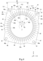
- FIG. 6 illustrates a stator core according to a preferred embodiment as viewed from a second axial side.
- a mobile unit 1000 of the present embodiment is a vehicle powered by a motor such as a hybrid electric vehicle (HEV), a plug-in hybrid electric vehicle (PHV), and an electric vehicle (EV).
- the mobile unit 1000 includes a vehicle body 110 , a drive device 100 for rotating wheels of the mobile unit 1000 , and a battery 120 for supplying electric power to the drive device 100 .
- the drive device 100 and the battery 120 are accommodated inside the vehicle body 110 .
- a vertical direction is defined and described based on a positional relationship when the mobile unit 1000 including the drive device 100 is located on a horizontal road surface R. That is, a relative positional relationship with respect to the vertical direction described in the following embodiment needs to be satisfied at least when the mobile unit 1000 including the drive device 100 is located on the horizontal road surface R.
- an XYZ coordinate system is illustrated appropriately as a three-dimensional orthogonal coordinate system.
- a Z-axis direction corresponds to the vertical direction.
- a +Z side is an upper side in the vertical direction
- a ⁇ Z side is a lower side in the vertical direction.
- the upper side and the lower side in the vertical direction will be referred to simply as the “upper side” and the “lower side”, respectively.
- An X-axis direction is a direction orthogonal to the Z-axis direction and is a front-rear direction of the mobile unit 1000 being a vehicle.
- a +X side corresponds to a front side in the mobile unit 1000
- a ⁇ X side corresponds to a rear side in the mobile unit 1000
- a Y-axis direction is a direction orthogonal to both the X-axis direction and the Z-axis direction, and is a left-right direction of the mobile unit 1000 , i.e., a vehicle lateral direction.
- a +Y side corresponds to a left side in the mobile unit 1000
- a ⁇ Y side corresponds to a right side in the mobile unit 1000 .
- the front-rear direction and the left-right direction are each a horizontal direction orthogonal to the vertical direction.
- the positional relationship in the front-rear direction is not limited to the positional relationship of the following embodiments, and the +X side may be the rear side of the mobile unit 1000 and the ⁇ X side may be the front side of the mobile unit 1000 .
- the +Y side is the right side of the mobile unit 1000
- the ⁇ Y side is the left side of the mobile unit 1000 .
- a “parallel direction” includes a substantially parallel direction
- an “orthogonal direction” includes a substantially orthogonal direction.
- a central axis J illustrated in the drawings as appropriate is a virtual axis extending in a direction intersecting the vertical direction. More specifically, the central axis J extends in the Y-axis direction orthogonal to the vertical direction, i.e., in the left-right direction of the mobile unit 1000 .
- a direction parallel to the central axis J is simply referred to as the “axial direction”
- a radial direction about the central axis J is simply referred to as the “radial direction”
- a circumferential direction about the central axis J, i.e., a direction around the central axis J is simply referred to as the “circumferential direction”.
- the left side (+Y side) in the axial direction is referred to as a “first axial side”
- the right side ( ⁇ Y side) in the axial direction is referred to as a “second axial side”.
- An arrow ⁇ appropriately illustrated in the drawing indicates the circumferential direction.
- a side advancing clockwise about the central axis J as viewed from the right side in the circumferential direction i.e., a side (+ ⁇ side) toward which the arrow ⁇ faces
- a side advancing counterclockwise about the central axis J as viewed from the right side in the circumferential direction i.e., a side ( ⁇ side) opposite to the side toward which the arrow ⁇ faces is referred to as a “second circumferential side”.
- the drive device 100 of the present preferred embodiment illustrated in FIG. 2 is mounted on the mobile unit 1000 being a vehicle to rotate an axle 64 of the mobile unit 1000 .
- the drive device 100 includes a rotary electric machine 10 and a transmission device 60 . That is, the mobile unit 1000 includes the rotary electric machine 10 and the transmission device 60 .
- the transmission device 60 is connected to the rotary electric machine 10 , and transmits rotation of the rotary electric machine 10 , i.e., rotation of a rotor 30 described later, to the axle 64 of the mobile unit 1000 .
- the transmission device 60 of the present preferred embodiment includes a gear housing 61 , a speed reducer 62 connected to the rotary electric machine 10 , and a differential gear 63 connected to the speed reducer 62 .
- the gear housing 61 internally accommodates the speed reducer 62 , the differential gear 63 , and oil O.
- the oil O is stored in a lower region in the gear housing 61 .
- the oil O circulates in a refrigerant flow path 90 described later.
- the oil O is used as a refrigerant for cooling the rotary electric machine 10 .
- the oil O is also used as lubricating oil for the speed reducer 62 and the differential gear 63 .
- an oil equivalent to an automatic transmission fluid (ATF) having a relatively low viscosity is preferably used to function as a refrigerant and a lubricating oil.
- ATF automatic transmission fluid
- the differential gear 63 includes a ring gear 63 a .
- the ring gear 63 a receives torque output from the rotary electric machine 10 and transmitted through the speed reducer 62 .
- the ring gear 63 a has a lower end portion immersed in the oil O stored in the gear housing 61 .
- the oil O scraped up is supplied to, for example, the speed reducer 62 and the differential gear 63 as a lubricating oil.
- the rotary electric machine 10 drives the drive device 100 .
- the rotary electric machine 10 is located, for example, on the second axial side from the transmission device 60 .
- the rotary electric machine 10 is a motor.
- the rotary electric machine 10 includes a motor housing 20 , the rotor 30 rotatable about the central axis J, a stator 40 , and a refrigerant feed part 50 .
- the motor housing 20 internally accommodates the rotor 30 and the stator 40 .
- the motor housing 20 is connected to the gear housing 61 on the second axial side.
- the motor housing 20 has a peripheral wall 21 , a partition wall 22 , and a lid 23 .
- the peripheral wall 21 and the partition wall 22 are each, for example, a part of a single member.
- the lid 23 is separate from, for example, the peripheral wall 21 and the partition wall 22 .
- the peripheral wall 21 has a cylindrical or substantially cylindrical shape that surrounds the central axis J and opens toward the second axial side.
- the partition wall 22 is connected to an end portion of the peripheral wall 21 on the first axial side.
- the partition wall 22 axially partitions the inside of the motor housing 20 and the inside of the gear housing 61 .
- the partition wall 22 has a partition wall opening 22 a that allows the inside of the motor housing 20 to communicate with the inside of the gear housing 61 .
- the partition wall 22 holds a bearing 34 .
- the lid 23 is fixed to an end portion of the peripheral wall 21 on the second axial side.
- the lid 23 closes the opening of the peripheral wall 21 on the second axial side.
- the lid 23 holds a bearing 35 .
- the motor housing 20 has a support portion 24 .
- the support portion 24 is provided on an inner peripheral surface of the peripheral wall 21 .
- the support portion 24 protrudes radially inward.
- the support portion 24 has a radially inner surface that is an arcuate curved surface about the central axis J.
- the radially inner surface of the support portion 24 is in contact with an outer peripheral surface 43 c of a stator core body 43 described later of the stator 40 . This causes the support portion 24 to support the stator 40 from radially outward.
- the support portion 24 extends in the axial direction.
- support portions 24 are provided at intervals along the circumferential direction.
- the support portion 24 includes an opposed support portion 24 a facing the refrigerant feed part 50 from the first circumferential side (+ ⁇ side).
- the opposed support portion 24 a is located above the stator 40 .
- the opposed support portion 24 a protrudes downward.
- the opposed support portion 24 a has a penetration groove 24 b that passes through the opposed support portion 24 a in the circumferential direction.
- the penetration groove 24 b is recessed radially outward from a radially inner surface of the opposed support portion 24 a .
- penetration grooves 24 b are provided at intervals in the axial direction in the present preferred embodiment. For example, two penetration grooves 24 b are provided.
- the opposed support portion 24 a has an end portion on the first axial side, the end portion being located on the second axial side from an end portion of the stator core body 43 described later on the first axial side.
- the motor housing 20 has an inner peripheral surface including a portion located on the first axial side of the opposed support portion 24 a , the portion radially facing the outer peripheral surface 43 c of the stator core body 43 across a gap.
- the rotor 30 faces the stator 40 across a gap.
- the rotor 30 includes a shaft 31 and a rotor body 32 .
- the rotor body 32 includes a rotor core, and a rotor magnet fixed to the rotor core. Torque of the rotor 30 is transmitted to the transmission device 60 .
- the shaft 31 is rotatable about the central axis J.
- the shaft 31 is rotatably supported by the bearings 34 and 35 .
- the shaft 31 is a hollow shaft.
- the shaft 31 has a cylindrical or cylindrical shape about the central axis J and extends axially.
- the shaft 31 is provided with a hole 33 that allows the inside of the shaft 31 to communicate with the outside of the shaft 31 .
- the shaft 31 extends across the inside of the motor housing 20 and the inside of the gear housing 61 .
- the shaft 31 has an end portion on the first axial side that protrudes into the gear housing 61 .
- the shaft 31 is connected at the end portion on the first axial side to the speed reducer 62 .
- the stator 40 radially faces the rotor 30 across a gap. More specifically, the stator 40 is located radially outward of the rotor 30 .
- the stator 40 is fixed inside the motor housing 20 .
- the stator 40 includes a stator core 41 and a coil assembly 42 .
- the stator core 41 is in an annular shape surrounding the central axis J of the rotary electric machine 10 .
- the stator core 41 is located radially outside the rotor 30 .
- the stator core 41 surrounds the rotor 30 .
- the stator core 41 is composed of, for example, plate members 41 a such as electromagnetic steel plates stacked in the axial direction.
- the plate members 41 a adjacent to each other in the axial direction are, for example, partially crimped and fixed to each other.
- the stator core 41 in the present preferred embodiment has a shape with four-fold symmetry around the central axis J.
- the stator core 41 includes a stator core body 43 and a protruding portion 49 .
- the stator core body 43 is in an annular shape surrounding the rotor 30 . More specifically, the stator core body 43 is in a cylindrical or substantially cylindrical shape about the central axis J, and opens on both sides in the axial direction.
- the stator core body 43 has the outer peripheral surface 43 c in a cylindrical or substantially cylindrical shape surrounding the rotor 30 . In the present preferred embodiment, the outer peripheral surface 43 c has a cylindrical or substantially cylindrical shape about the central axis J.
- the outer peripheral surface 43 c constitutes a part of an outer peripheral surface of the stator core 41 .
- the outer peripheral surface of the stator core 41 i.e., a radially outer surface of the stator core 41 , is composed of the outer peripheral surface 43 c and a radially outer surface of the protruding portion 49 .
- the outer peripheral surface 43 c is supported from radially outside by the support portion 24 provided on the inner peripheral surface of the motor housing 20 .
- the outer peripheral surface 43 c is disposed radially facing a portion, which is provided with no support portion 24 , of the inner peripheral surface of the motor housing 20 across a gap.
- the stator core body 43 includes a core back 43 a in a cylindrical or substantially cylindrical shape extending axially and teeth 43 b extending radially inward from the core back 43 a . That is, the stator core 41 includes the core back 43 a and the teeth 43 b .
- the core back 43 a is in an annular shape surrounding the central axis J.
- the core back 43 a has an outer peripheral surface that is the outer peripheral surface 43 c of the stator core body 43 . That is, the core back 43 a has the outer peripheral surface 43 c in a cylindrical or substantially cylindrical shape.
- the teeth 43 b are disposed at equal intervals over one circumference along the circumferential direction.
- the core back 43 a has flux barrier portions 48 disposed at intervals in the circumferential direction.
- the term, “flux barrier portion” is a portion capable of preventing a flow of magnetic flux. That is, the magnetic flux is less likely to pass through the flux barrier portion.
- the flux barrier portion is not particularly limited as long as it can prevent a flow of magnetic flux, and may include a void or a non-magnetic portion such as a resin portion.
- the flux barrier portions 48 are each a void portion composed of a hole axially passing through the core back 43 a .
- the hole constituting each of the flux barrier portions 48 is a circular hole, for example.
- the flux barrier portions 48 are disposed at equal intervals over one circumference along the circumferential direction.
- the flux barrier portions 48 are disposed radially outside respective slot portions provided between the corresponding teeth 43 b adjacent to each other in the circumferential direction.
- the flux barrier portions 48 each have an inner diameter equal to or less than a distance between the teeth 43 b adjacent to each other in the circumferential direction, i.e., a dimension of each of the slot portions in the circumferential direction.
- the flux barrier portions 48 in the present preferred embodiment are located at the center between an inner peripheral surface and the outer peripheral surface 43 c of the core back 43 a in the radial direction.
- the protruding portion 49 protrudes radially outward from the outer peripheral surface 43 c of the core back 43 a .
- the protruding portion 49 is a fixing portion fixed to the motor housing 20 . As illustrated in FIG. 5 , the protruding portion 49 extends axially.
- the protruding portion 49 extends from, for example, an end portion of the stator core body 43 on the first axial side to an end portion of the stator core body 43 on the second axial side.
- Multiple protruding portions 49 are provided at intervals in the circumferential direction. For example, four protruding portions 49 are provided.
- the protruding portions 49 includes a first protruding portion 44 , a second protruding portion 45 , a third protruding portion 46 , and a fourth protruding portion 47 .
- the first protruding portion 44 , the second protruding portion 45 , the third protruding portion 46 , and the fourth protruding portion 47 are disposed apart from each other in the circumferential direction.
- the first protruding portion 44 and the second protruding portion 45 are located above the central axis J.
- the third protruding portion 46 and the fourth protruding portion 47 are located below the central axis J.
- the first protruding portion 44 , the second protruding portion 45 , the third protruding portion 46 , and the fourth protruding portion 47 are disposed at equal intervals over one circumference in the circumferential direction, for example.
- the first protruding portion 44 , the second protruding portion 45 , the third protruding portion 46 , and the fourth protruding portion 47 are identical in shape to each other, for example. Thus, the following description may not include description of shape of the protruding portions 49 other than the first protruding portion 44 .
- each protruding portion 49 has an asymmetrical shape in the circumferential direction.
- the first protruding portion 44 is provided in an upper front end portion of the stator core body 43 .
- the first protruding portion 44 protrudes upward and diagonally forward from the stator core body 43 .
- the second protruding portion 45 is provided in an upper rear end portion of the stator core body 43 .
- the second protruding portion 45 protrudes upward and diagonally rearward from the stator core body 43 .
- the third protruding portion 46 is provided in a lower rear end portion of the stator core body 43 .
- the third protruding portion 46 protrudes downward and diagonally rearward from the stator core body 43 .
- the fourth protruding portion 47 is provided in a lower front end portion of the stator core body 43 .
- the fourth protruding portion 47 protrudes downward and diagonally forward from the stator core body 43 .
- the first protruding portion 44 is located on the first circumferential side (+ ⁇ side) from the refrigerant feed part 50 .
- the first protruding portion 44 is located on the first circumferential side from the opposed support portion 24 a .
- the first protruding portion 44 is located on the first circumferential side from a vertex VP on an upper side of the stator core body 43 .
- the vertex VP is located uppermost in the outer peripheral surface 43 c of the stator core body 43 .
- the vertex VP is an intersection at which the outer peripheral surface 43 c of the stator core body 43 intersects with a virtual line CL extending in the vertical direction through the central axis J.
- the vertex VP is supported from above by the opposed support portion 24 a , for example.
- the first protruding portion 44 has a radially outer end portion that is located below the vertex VP.
- the first protruding portion 44 is disposed away from the inner peripheral surface of the motor housing 20 .
- the first protruding portion 44 decreases in circumferential dimension radially outward.
- the radially outer end portion of the first protruding portion 44 has an outline in an arc shape that is convex radially outward as viewed in the axial direction.
- the first protruding portion 44 has a first side surface 44 a directed toward the second circumferential side ( ⁇ side) is an inclined surface inclined toward the first circumferential side (+ ⁇ side) from the outer peripheral surface 43 c of the stator core body 43 radially outward.
- the first protruding portion 44 has the first side surface 44 a as an inclined surface extending radially outward and toward the first circumferential side from the outer peripheral surface 43 c of the core back 43 a .
- the first side surface 44 a faces upward and diagonally forward.
- the first side surface 44 a has a radially inner end portion that is connected to the outer peripheral surface 43 c of the stator core body 43 , i.e., the outer peripheral surface 43 c of the core back 43 a .
- the first side surface 44 a extends along a tangent line TL 1 a tangent to a connection portion P 1 a at which the radially inner end portion of the first side surface 44 a is connected to the outer peripheral surface 43 c of the core back 43 a .
- the connection portion P 1 a is located forward and downward from the vertex VP.
- the tangent line TL 1 a inclines at an angle with respect to the front-back direction (X-axis direction) as viewed in the axial direction.
- the tangent line TL 1 a is located more downward toward the front side.
- the first side surface 44 a is smoothly connected to the outer peripheral surface 43 c of the stator core body 43 .
- the first side surface 44 a extends linearly, for example, as viewed in the axial direction.
- the first side surface 44 a extends forward and diagonally downward from the connection portion P 1 a as viewed in the axial direction.
- the first side surface 44 a is located more downward with distance from a first feed port 54 described later in the circumferential direction.
- the first side surface 44 a is located more downward toward the front side of the mobile unit 1000 on which the drive device 100 is mounted.
- the first protruding portion 44 has a second side surface 44 b directed toward the first circumferential side (+ ⁇ side), and the second side surface 44 b is an inclined surface inclined toward the second circumferential side ( ⁇ side) from the outer peripheral surface 43 c of the stator core body 43 radially outward.
- the second side surface 44 b faces forward and diagonally downward.
- the second side surface 44 b is connected at its radially inner end portion to the outer peripheral surface 43 c of the stator core body 43 .
- the second side surface 44 b extends in a direction inclined radially outward from a tangent line TL 1 b tangent to a connection portion P 1 b at which the radially inner end portion of the second side surface 44 b is connected to the outer peripheral surface 43 c of the stator core body 43 .
- the connection portion P 1 b is located forward and downward from the connection portion P 1 a .
- the tangent line TL 1 b inclines at an angle with respect to the front-back direction as viewed in the axial direction.
- the tangent line TL 1 b is located more downward toward the front side.
- the tangent line TL 1 b inclines more in the front-back direction than the tangent line TL 1 a in the front-back direction.
- the second side surface 44 b is smoothly connected to the outer peripheral surface 43 c of the stator core body 43 .
- the second side surface 44 b extends linearly, for example, as viewed in the axial direction.
- the second side surface 44 b extends upward and diagonally forward from the connection portion P 1 b as viewed in the axial direction.
- the second protruding portion 45 is located on the second circumferential side ( ⁇ side) from the refrigerant feed part 50 .
- the second protruding portion 45 is located on the second circumferential side from the opposed support portion 24 a .
- the second protruding portion 45 is located on the second circumferential side from the vertex VP on the upper side of the stator core body 43 .
- the second protruding portion 45 has a radial outer end portion that is located above the radially outer end portion of the first protruding portion 44 .
- the second protruding portion 45 has an upper end portion that is located above the vertex VP, for example.
- the second protruding portion 45 has a third side surface 45 a directed toward the first circumferential side (+ ⁇ side), and the third side surface 45 a is an inclined surface inclined toward the second circumferential side ( ⁇ side) from the outer peripheral surface 43 c of the stator core body 43 radially outward.
- the third side surface 45 a faces upward and diagonally forward.
- the third side surface 45 a is connected at its radially inner end portion to the outer peripheral surface 43 c of the stator core body 43 .
- the third side surface 45 a extends in a direction inclined radially outward from a tangent line TL 2 a tangent to a connection portion P 2 a at which the radially inner end portion of the third side surface 45 a is connected to the outer peripheral surface 43 c of the stator core body 43 .
- the connection portion P 2 a is located rearward and downward from the vertex VP.
- the tangent line TL 2 a inclines at an angle with respect to the front-back direction as viewed in the axial direction.
- the tangent line TL 2 a is located more upward toward the front side.
- the third side surface 45 a is smoothly connected to the outer peripheral surface 43 c of the stator core body 43 .
- the third side surface 45 a extends linearly, for example, as viewed in the axial direction.
- the third side surface 45 a extends rearward and diagonally upward from the connection portion P 2 a as viewed in the axial direction.
- the second protruding portion 45 has a fourth side surface 45 b directed toward the second circumferential side ( ⁇ side), and the fourth side surface 45 b is an inclined surface inclined toward the first circumferential side (+ ⁇ side) from the outer peripheral surface 43 c of the stator core body 43 radially outward. That is, the second protruding portion 45 has the fourth side surface 45 b as an inclined surface extending radially outward and toward the first circumferential side from the outer peripheral surface 43 c of the core back 43 a . In the present preferred embodiment, the fourth side surface 45 b faces rearward and diagonally upward.
- the fourth side surface 45 b has a radially inner end portion that is connected to the outer peripheral surface 43 c of the stator core body 43 , i.e., the outer peripheral surface 43 c of the core back 43 a .
- the fourth side surface 45 b extends along a tangent line TL 2 b tangent to a connection portion P 2 b at which the radially inner end portion of the fourth side surface 45 b is connected to the outer peripheral surface 43 c of the stator core body 43 .
- the connection portion P 2 b is located rearward and downward from the connection portion P 2 a .
- the tangent line TL 2 b inclines at an angle with respect to the front-back direction as viewed in the axial direction.
- the tangent line TL 2 b is located more upward toward the front side.
- the tangent line TL 2 b inclines more in the front-back direction than the tangent line TL 2 a in the front-back direction.
- the fourth side surface 45 b is smoothly connected to the outer peripheral surface 43 c of the stator core body 43 .
- the fourth side surface 45 b extends linearly, for example, as viewed in the axial direction.
- the fourth side surface 45 b extends upward and diagonally forward from the connection portion P 2 b as viewed in the axial direction.
- the stator core 41 has a hole 49 a provided in a radially outer portion of the stator core 41 .
- the radially outer portion of the stator core 41 is located radially outside the center of the stator core 41 in the radial direction.
- the radially outer portion of the stator core 41 includes, for example, the core back 43 a and the protruding portion 49 .
- the hole 49 a is provided in the protruding portion 49 .
- One hole 49 a is provided for each protruding portion 49 .
- the hole 49 a extends in the axial direction.
- the hole 49 a is a through-hole passing through the protruding portion 49 in the axial direction.
- the hole 49 a is, for example, a circular hole.
- a bolt 25 extending in the axial direction passes.
- the bolt 25 is allowed to pass through the hole 49 a from the second axial side ( ⁇ Y side) and is tightened into a female screw hole provided in the motor housing 20 .
- the protruding portion 49 is fixed to the motor housing 20 by the bolt 25 .
- a washer 26 is provided between the protruding portion 49 and the bolt 25 .
- the washer 26 is in a plate or substantially plate shape with a plate surface directed in the axial direction, and is in an annular shape surrounding the bolt 25 .
- the stator core 41 has a weld 80 provided on the radially outer surface of the stator core 41 .
- the weld 80 extends in the axial direction. More specifically, the weld 80 extends from an end portion of the stator core 41 on the first axial side to an end portion thereof on the second axial side.
- the weld 80 is formed by welding a part of the radially outer surface of the stator core 41 .
- the weld 80 is formed by welding a groove bottom surface of a weld groove 41 b provided in the radially outer surface of the stator core 41 .
- the weld groove 41 b is recessed radially inward from the radially outer surface of the stator core 41 .
- the weld groove 41 b extends in the axial direction. More specifically, the weld groove 41 b extends from the end portion of the stator core 41 on the first axial side to the end thereof on the second axial side.
- the weld groove 41 b is open on both sides in the axial direction.
- the groove bottom surface of the weld groove 41 b is an inner surface of the weld groove 41 b , facing radially outside.
- the weld 80 is formed by a welding method that is not particularly limited, and that may be arc welding or laser welding.
- the weld 80 is provided over the plate members 41 a to fix the plate members 41 a to each other. In the present preferred embodiment, multiple welds 80 are provided.
- the multiple welds 80 are disposed at intervals along the circumferential direction. As illustrated in FIG. 6 , the multiple welds 80 are disposed at equal angles along the circumferential direction in the present preferred embodiment. That is, a circumferential angle ⁇ between the welds 80 adjacent to each other in the circumferential direction on the radially outer surface of the stator core 41 is identical in all the welds 80 . In the present preferred embodiment, twelve welds 80 are provided. The twelve welds 80 are provided at respective positions that divide the radially outer surface of the stator core 41 into twelve equal parts in the circumferential direction. In the present preferred embodiment, the angle ⁇ is 30°.
- the multiple welds 80 are disposed on the radially outer surface of the stator core 41 in a rotationally symmetrical manner around the central axis J.
- the multiple welds 80 are disposed on the radially outer surface of the stator core 41 with four-fold symmetry around the central axis J. That is, when the stator core 41 is rotated by 90° around the central axis J, each of the welds 80 in the stator core 41 after rotation overlaps the corresponding one of the welds 80 in the stator core 41 before rotation.
- the multiple welds 80 include a first weld 81 , a second weld 82 , and a third weld 83 .
- the first weld 81 is a weld 80 provided on a virtual line IL 1 connecting the hole 49 a and the central axis J as viewed in the axial direction on the radially outer surface of the stator core 41 .
- the virtual line IL 1 extends radially through the center of the hole 49 a and the central axis J as viewed in the axial direction.
- the virtual line IL 1 passes through the circumferential center of one tooth 43 b and the circumferential center between the flux barrier portions 48 adjacent to each other in the circumferential direction as viewed in the axial direction.
- the first weld 81 is provided on the radially outer surface of the protruding portion 49 . More specifically, the first weld 81 is provided on the radially outer surface of a radially outer end portion of the protruding portion 49 .
- the first weld 81 is located radially outside the hole 49 a.
- first welds 81 are provided.
- One first weld 81 is provided for each of the first protruding portion 44 , the second protruding portion 45 , the third protruding portion 46 , and the fourth protruding portion 47 . That is, four first welds 81 are provided in total in the present preferred embodiment.
- a distance L 2 between the flux barrier portion 48 and the hole 49 a is larger than a distance L 1 between the first weld 81 and the hole 49 a as viewed in the axial direction.
- the distance L 1 is the shortest distance between the first weld 81 and the hole 49 a in the protruding portion 49 provided with the first weld 81 .
- the distance L 1 is a radial distance between the first weld 81 and the hole 49 a .
- the distance L 2 is the shortest distance between the hole 49 a and the flux barrier portion 48 closest to the hole 49 a .
- the distance L 2 is, for example, twice or more the distance L 1 .
- the second weld 82 is a weld 80 provided on the outer peripheral surface 43 c of the core back 43 a . As illustrated in FIG. 6 , multiple second welds 82 are provided in the present preferred embodiment. The second welds 82 are each provided at a portion of the outer peripheral surface 43 c located between the protruding portions 49 adjacent to each other in the circumferential direction.
- the second welds 82 are provided respective portions including: a portion of the outer peripheral surface 43 c located between the first protruding portion 44 and the second protruding portion 45 in the circumferential direction; a portion of the outer peripheral surface 43 c located between the second protruding portion 45 and the third protruding portion 46 in the circumferential direction; a portion of the outer peripheral surface 43 c located between the third protruding portion 46 and the fourth protruding portion 47 in the circumferential direction; and a portion of the outer peripheral surface 43 c located between the fourth protruding portion 47 and the first protruding portion 44 in the circumferential direction. That is, four second welds 82 are provided in total in the present preferred embodiment.
- Each of the second welds 82 is disposed between the protruding portions 49 and disposed closer to the protruding portion 49 on the second circumferential side ( ⁇ side).
- the second weld 82 provided in the portion of the outer peripheral surface 43 c located between the first protruding portion 44 and the second protruding portion 45 in the circumferential direction is provided at a position closer to the third side surface 45 a than to the first side surface 44 a in the circumferential direction.
- the second weld 82 provided in the portion of the outer peripheral surface 43 c located between the first protruding portion 44 and the second protruding portion 45 in the circumferential direction is located on the second circumferential side from the vertex VP.
- the second weld 82 is located radially outside a portion of the core back 43 a located between the flux barrier portions 48 adjacent to each other in the circumferential direction.
- the second weld 82 is located radially outside one tooth 43 b .
- a virtual line IL 2 connecting the second weld 82 and the central axis J passes through the circumferential center of one tooth 43 b and the circumferential center between the flux barrier portions 48 adjacent to each other in the circumferential direction as viewed in the axial direction.
- the third weld 83 is a weld 80 provided on a portion of the radially outer surface of the protruding portion 49 , the portion being different in circumferential position from the hole 49 a .
- multiple third welds 83 are provided.
- One third weld 83 is provided for each of the first protruding portion 44 , the second protruding portion 45 , the third protruding portion 46 , and the fourth protruding portion 47 . That is, four third welds 83 are provided in total in the present preferred embodiment.
- the third weld 83 is provided on a side surface of each protruding portion 49 facing the second circumferential side ( ⁇ side). More specifically, the third weld 83 is provided in a circumferential end portion of the side surface of each protruding portion 49 facing the second circumferential side, the circumferential end portion being on a side ( ⁇ side) close to the outer peripheral surface 43 c of the core back 43 a .
- the first protruding portion 44 has a side surface directed to the second circumferential side that is the first side surface 44 a as an inclined surface.
- the second protruding portion 45 has a side surface directed to the second circumferential side that is the fourth side surface 45 b as an inclined surface.
- the third weld 83 is located radially outside a portion of the core back 43 a located between the flux barrier portions 48 adjacent to each other in the circumferential direction.
- the third weld 83 is located radially outside one tooth 43 b .
- a virtual line IL 3 connecting the third weld 83 and the central axis J passes through the circumferential center of one tooth 43 b and the circumferential center between the flux barrier portions 48 adjacent to each other in the circumferential direction.
- the first weld 81 , the second weld 82 , and the third weld 83 are alternately disposed in this order on the radially outer surface of the stator core 41 toward the first circumferential side (+ ⁇ side).
- the second weld 82 and the third weld 83 are each provided one by one on an upper surface, a front surface side (on +X side), a lower surface, and a rear surface (on ⁇ X side) of the stator core 41 .
- the first weld 81 is provided in each of boundary portions including: a boundary portion between the front surface and the upper surface of the stator core 41 ; a boundary portion between the upper surface and the rear surface of the stator core 41 ; a boundary portion between the rear surface and the lower side of the stator core 41 ; and a boundary portion between the lower surface and the front surface of the stator core 41 .
- the first weld 81 is located radially outside the second weld 82 and the third weld 83 .
- the coil assembly 42 includes multiple coils 42 c attached to the stator core 41 along the circumferential direction.
- the multiple coils 42 c are mounted on the respective teeth 43 b of the stator core 41 with respective insulators (not illustrated) interposed therebetween.
- the multiple coils 42 c are disposed along the circumferential direction. More specifically, the multiple coils 42 c are disposed at equal intervals along the circumferential direction.
- the coil assembly 42 may have a binding member or the like for binding each of the coils 42 c , or may have a jump wire connecting the coils 42 c to each other.
- the coil assembly 42 includes coil ends 42 a and 42 b that protrude axially from the stator core 41 .
- the coil end 42 a protrudes from the stator core 41 toward the first axial side.
- the coil end 42 b protrudes from the stator core 41 toward the second axial side.
- the coil end 42 a includes a portion of each of the coils 42 c included in the coil assembly 42 , the portion protruding from the stator core 41 toward the first axial side.
- the coil end 42 b includes a portion of each of the coils 42 c included in the coil assembly 42 , the portion protruding from the stator core 41 toward the second axial side.
- the coil ends 42 a and 42 b are each in an annular or substantially annular shape about the central axis J.
- the coil ends 42 a and 42 b each may have a binding member or the like for binding each of the coils 42 c , or may have a jump wire connecting the coils 42 c to each other.
- the refrigerant feed part 50 is in a tubular shape extending in the axial direction.
- the refrigerant feed part 50 is a pipe extending in the axial direction in the present preferred embodiment.
- the refrigerant feed part 50 has axially opposite end portions supported by the motor housing 20 .
- the refrigerant feed part 50 has the end portion on the first axial side that is supported by, for example, the partition wall 22 .
- the refrigerant feed part 50 has the end portion on the second axial side that is supported by, for example, the lid 23 .
- the refrigerant feed part 50 is located radially outside the stator 40 . In the present preferred embodiment, the refrigerant feed part 50 is located above the stator 40 .
- the refrigerant feed part 50 is located between the first protruding portion 44 and the second protruding portion 45 in the circumferential direction.
- the refrigerant feed part 50 is located between the opposed support portion 24 a and the second protruding portion 45 in the circumferential direction.
- the refrigerant feed part 50 is disposed at a position closer to the second protruding portion 45 than to the first protruding portion 44 in the circumferential direction.
- the refrigerant feed part 50 is located, for example, above a boundary portion between the second protruding portion 45 and the stator core body 43 .
- the refrigerant feed part 50 is located above the connection portion P 2 a .
- the refrigerant feed part 50 is disposed overlapping an end portion of the third side surface 45 a of the second protruding portion 45 on the first circumferential side (+ ⁇ side) and the outer peripheral surface 43 c of the stator core body 43 .
- the refrigerant feed part 50 includes a wide portion 51 , an inlet portion 52 , and an outlet portion 53 .
- the entire refrigerant feed part 50 excluding the inlet portion 52 and the outlet portion 53 is the wide portion 51 in the present preferred embodiment.
- the wide portion 51 is a body portion of the refrigerant feed part 50 .
- a placement relationship between the wide portion 51 and the stator core 41 is similar to a placement relationship between the refrigerant feed part 50 and the stator core 41 described above.
- the wide portion 51 is located radially outside the stator 40 . In the present preferred embodiment, the wide portion 51 is located above the stator 40 .
- the wide portion 51 is located between the opposed support portion 24 a and the second protruding portion 45 in the circumferential direction.
- the wide portion 51 has an axial dimension that is larger than an axial dimension of the stator core 41 .
- the wide portion 51 protrudes on both sides in the axial direction from the stator core 41 .
- the wide portion 51 is disposed over an upper side of the stator core 41 and an upper side of the coil ends 42 a and 42 b .
- the wide portion 51 includes a portion that protrudes from the stator core 41 toward the first axial side and that is located above the coil end 42 a .
- the wide portion 51 includes a portion that protrudes from the stator core 41 toward the second axial side and that is located above the coil end 42 b.
- the wide portion 51 has a circumferential dimension that is larger than its radial dimension. As illustrated in FIG. 3 , the wide portion 51 is, for example, in a shape in which a cylinder is crushed in the radial direction, i.e., a substantially elliptical tubular shape flat in the radial direction.
- the wide portion 51 has a radially inner surface that is a facing surface 51 a facing the outer peripheral surface of the stator core 41 in the radial direction.
- the facing surface 51 a faces the outer peripheral surface 43 c of the stator core body 43 in the radial direction.
- the facing surface 51 a is in a shape along the outer peripheral surface of the stator core 41 , i.e., a shape along the outer peripheral surface 43 c of the stator core body 43 in the present preferred embodiment.
- the facing surface 51 a is a curved surface that is concave radially outward. As viewed in the axial direction, the facing surface 51 a is in an arc shape centered on the central axis J, the arc shape being convex radially outward.
- a radial gap between the facing surface 51 a and the outer peripheral surface 43 c is, for example, smaller than a radial depth of the penetration groove 24 b.
- the inlet portion 52 is connected to an end portion of the wide portion 51 on the first axial side.
- the inlet portion 52 is in a cylindrical or substantially cylindrical shape that opens toward the first axial side.
- the inlet portion 52 is an end portion of the refrigerant feed part 50 on the first axial side.
- the inlet portion 52 is, for example, fitted into a hole (not illustrated) provided in the partition wall 22 and supported by the partition wall 22 . From the inlet portion 52 , oil O flows into the inside of the refrigerant feed part 50 .
- the outlet portion 53 is connected to an end portion of the wide portion 51 on the second axial side.
- the outlet portion 53 is in a cylindrical or substantially cylindrical shape that opens toward the second axial side.
- the outlet portion 53 is an end portion of the refrigerant feed part 50 on the second axial side.
- the outlet portion 53 is, for example, fitted into a hole (not illustrated) provided in the lid 23 and supported by the lid 23 . From the outlet portion 53 , the oil O having flowed into the inside of the refrigerant feed part 50 from the inlet portion 52 partially flows out.
- the oil O in the refrigerant feed part 50 flows in a direction from the first axial side toward the second axial side. That is, the oil O in the refrigerant feed part 50 flows in the direction in which the first axial side is an upstream side and the second axial side is a downstream side.
- the refrigerant feed part 50 has a feed port 50 a for feeding the oil O as a refrigerant to the stator 40 .
- the feed port 50 a is an injection port that injects partially the oil O having flowed into the refrigerant feed part 50 to the outside of the refrigerant feed part 50 .
- Multiple feed ports 50 a are provided.
- all the feed ports 50 a are provided in the wide portion 51 . That is, the wide portion 51 has at least one feed port 50 a.
- the feed port 50 a is composed of a hole passing through a wall portion of the refrigerant feed part 50 in a tubular or substantially tubular shape from an inner peripheral surface to an outer peripheral surface of the wall portion.
- the feed port 50 a is an opening of the hole that passes through the wall portion of the refrigerant feed part 50 in a tubular or substantially tubular shape from the inner peripheral surface to the outer peripheral surface of the wall portion, the opening being open in the outer peripheral surface of the refrigerant feed part 50 .
- the feed port 50 a is, for example, in a circular or substantially circular shape.
- the feed port 50 a provided in the wide portion 51 in the present preferred embodiment includes a first feed port 54 , a second feed port 55 , and a third feed port 56 .
- the first feed port 54 is a feed port 50 a for feeding the oil O as a refrigerant to the stator core 41 .
- the first feed port 54 is a feed port 50 a that opens toward the first circumferential side (+ ⁇ side). As illustrated in FIG. 3 , the first feed port 54 is located on the second circumferential side ( ⁇ side) from the vertex VP of the stator core body 43 in the present preferred embodiment.
- the first feed port 54 is located above the stator core body 43 .
- the opposed support portion 24 a and the first protruding portion 44 are located on the first circumferential side from the first feed port 54 .
- the first feed port 54 is provided in a radially inward portion in an end portion of the wide portion 51 on the first circumferential side (+ ⁇ side). In the present preferred embodiment, the first feed port 54 opens in a direction inclined radially inward with respect to the circumferential direction. As illustrated in FIG. 4 , multiple first feed ports 54 are provided in the present preferred embodiment.
- the first feed port 54 includes, for example, three first feed ports 54 a , 54 b , and 54 c.
- the first feed port 54 a , the first feed port 54 b , and the first feed port 54 c are disposed side by side at an interval in this order from the first axial side toward the second axial side.
- the first feed ports 54 a and 54 b are located on the first axial side from the axial center of the stator core 41 .
- the first feed port 54 c is located on the second axial side from the axial center of the stator core 41 .
- An axial distance between the first feed port 54 a and the first feed port 54 b is smaller than an axial distance between the first feed port 54 b and the first feed port 54 c.
- the first feed port 54 a is located on the first axial side from the opposed support portion 24 a . That is, the first feed port 54 a is a first feed port 54 disposed at a position different from the opposed support portion 24 a in the axial direction of the central axis J in the present preferred embodiment.
- the first feed port 54 a has an inner diameter smaller than an inner diameter of each of the other first feed ports 54 b and 54 c.
- the first feed ports 54 b and 54 c are identical in axial position to the corresponding two penetration grooves 24 b provided in the opposed support portion 24 a . As illustrated in FIG. 3 , the first feed ports 54 b and 54 c are each a first feed port 54 that opens toward a penetration groove 24 b .
- a first feed port opens toward a penetration groove means that only at least a part of the first feed port need to overlap the inside of the penetration groove as viewed in a direction in which the first feed port opens.
- the first feed ports 54 b and 54 c overlap the inside of the corresponding penetration grooves 24 b and the outer peripheral surface 43 c of the stator core body 43 as viewed in the direction in which the first feed ports 54 b and 54 c open.
- the direction in which the first feed port 54 opens is, for example, a direction in which a hole constituting the first feed port 54 passes through a wall of the refrigerant feed part 50 from an inner peripheral surface to an outer peripheral surface of the wall.
- the oil O to be discharged from the first feed ports 54 b and 54 c is injected in the direction in which the first feed ports 54 b and 54 c open, and is fed to the outer peripheral surface 43 c of the stator core body 43 .
- the oil O fed from the first feed ports 54 b and 54 c to the outer peripheral surface 43 c flows on the outer peripheral surface 43 c toward the first circumferential side (+ ⁇ side) and passes through the corresponding penetration grooves 24 b in the circumferential direction.
- the oil O having passed through the penetration grooves 24 b flows from the outer peripheral surface 43 c to the first side surface 44 a of the first protruding portion 44 , and flows over the first protruding portion 44 toward the first circumferential side.
- the oil O having flowed over the first protruding portion 44 flows downward between the second side surface 44 b and the inner peripheral surface of the motor housing 20 , and is fed to a front side portion of the outer peripheral surface 43 c of the stator core body 43 .
- the second feed port 55 is a feed port 50 a for feeding the oil O as a refrigerant to the stator core 41 .
- the second feed port 55 is a feed port 50 a that opens toward the second circumferential side ( ⁇ side).
- the second feed port 55 is located on the second circumferential side from the vertex VP of the stator core body 43 .
- the second feed port 55 is located above the stator core body 43 .
- the second protruding portion 45 is located on the second circumferential side from the second feed port 55 .
- the second feed port 55 is located above an end portion of the second protruding portion 45 on the first circumferential side (+ ⁇ side).
- the second feed port 55 is provided in a radially outward portion in an end portion of the wide portion 51 on the second circumferential side ( ⁇ side).
- the second feed port 55 opens in a direction inclined radially outward with respect to the circumferential direction.
- the second feed port 55 overlaps a portion of the inner peripheral surface of the motor housing 20 , the portion being disposed facing an upper side of the second protruding portion 45 .
- the direction in which the second feed port 55 opens is, for example, a direction in which a hole constituting the second feed port 55 passes through the wall of the refrigerant feed part 50 from the inner peripheral surface to the outer peripheral surface of the wall.
- multiple second feed ports 55 are provided in the present preferred embodiment.
- the second feed port 55 includes, for example, three second feed ports 55 a , 55 b , and 55 c.
- the second feed port 55 a , the second feed port 55 b , and the second feed port 55 c are disposed side by side at an interval in this order from the first axial side toward the second axial side.
- the second feed port 55 a is located on the first axial side from the axial center of the stator core 41 .
- the second feed port 55 b is located at an axial position that is substantially identical to the axial center of the stator core 41 .
- the second feed port 55 c is located on the second axial side from the axial center of the stator core 41 .
- An axial distance between the second feed port 55 a and the second feed port 55 b is, for example, equal to an axial distance between the second feed port 55 b and the second feed port 55 c .
- the second feed ports 55 a , 55 b , and 55 c each have an equal inner diameter, for example.
- the inner diameter of each of the second feed ports 55 a , 55 b , and 55 c is, for example, equal to the inner diameter of each of the first feed ports 54 b and 54 c.
- the oil O to be discharged from the second feed port 55 is injected in the direction in which the second feed port 55 opens, and is fed to a portion of the inner peripheral surface of the motor housing 20 , the portion being located above the second protruding portion 45 .
- the oil O fed from the second feed port 55 to the inner peripheral surface of the motor housing 20 flows along the inner peripheral surface of the motor housing 20 toward the second circumferential side ( ⁇ side), and then flows over the second protruding portion 45 toward the second circumferential side.
- the oil O having flowed over the second protruding portion 45 flows downward between fourth side surface 45 b and the inner peripheral surface of the motor housing 20 , and is fed to a rear side portion of the outer peripheral surface 43 c of the stator core body 43 .
- the first feed port 54 and the second feed port 55 are disposed by being displaced from each other in the axial direction of the central axis J.
- the first feed port 54 a is disposed by being slightly displaced from the second feed port 55 a toward the second axial side.
- the first feed port 54 b is disposed by being relatively largely displaced from the second feed port 55 b toward the first axial side.
- the first feed port 54 c is disposed by being slightly displaced from the second feed port 55 c toward the first axial side.
- the first feed port and the second feed port are disposed by being displaced from each other in the axial direction
- the first feed port and the second feed port may be partially disposed at an identical axial position as long as the center of the first feed port and the center of the second feed port are disposed by being displaced from each other in the axial direction.
- the first feed port 54 a and the second feed port 55 a are partially disposed at an identical axial position.
- the first feed port 54 c and the second feed port 55 c are partially disposed at an identical axial position.
- the first feed port 54 b and the second feed port 55 b are disposed by being displaced from each other in the axial direction as a whole.
- the third feed port 56 is a feed port 50 a for feeding the oil O as a refrigerant to the coil ends 42 a and 42 b .
- the third feed port 56 opens downward.
- the third feed port 56 includes a third feed port 56 a disposed above the coil end 42 a and a third feed port 56 b disposed above the coil end 42 b .
- the third feed port 56 a is located on the first axial side from the first feed port 54 and the second feed port 55 .
- the third feed port 56 b is located on the second axial side from the first feed port 54 and the second feed port 55 .
- multiple third feed ports 56 a and multiple third feed ports 56 b are provided.
- five third feed ports 56 a and five third feed ports 56 b are provided.
- the five third feed ports 56 a are disposed at intervals around the wide portion 51 .
- the five third feed ports 56 b are also disposed at intervals around the wide portion 51 .
- the drive device 100 in the present preferred embodiment is provided with the refrigerant flow path 90 through which the oil O as a refrigerant circulates.
- the refrigerant flow path 90 is provided throughout from the inside of the motor housing 20 to the inside of the gear housing 61 .
- the refrigerant flow path 90 allows the oil O stored in the gear housing 61 to be fed to the rotary electric machine 10 and to return to the inside of the gear housing 61 again.
- the refrigerant flow path 90 is provided with a pump 71 , a cooler 72 , and the refrigerant feed part 50 .
- the refrigerant flow path 90 includes a first flow path portion 91 , a second flow path portion 92 , a third flow path portion 93 , and a fourth flow path portion 94 .
- the first flow path portion 91 , the second flow path portion 92 , and the third flow path portion 93 are each provided, for example, in a wall of the gear housing 61 .
- the fourth flow path portion 94 is provided, for example, in the lid 23 .
- the first flow path portion 91 allows a portion with the oil O stored, inside the gear housing 61 , to communicate with the pump 71 .
- the second flow path portion 92 allows the pump 71 to communicate with the cooler 72 .
- the third flow path portion 93 allows the cooler 72 to communicate with the inside of the refrigerant feed part 50 .
- the third flow path portion 93 communicates with the end portion of the refrigerant feed part 50 on the first axial side.
- the fourth flow path portion 94 allows the inside of the refrigerant feed part 50 to communicate with the inside of the shaft 31 .
- the fourth flow path portion 94 communicates with the end portion of the refrigerant feed part 50 on the second axial side and an end portion of the shaft 31 on the second axial side.
- the oil O stored in the gear housing 61 is sucked up through the first flow path portion 91 and flows into the cooler 72 through the second flow path portion 92 .
- the oil O having flowed into the cooler 72 is cooled in the cooler 72 , and then flows through the third flow path portion 93 to the inside of the refrigerant feed part 50 .
- the oil O having flowed into the refrigerant feed part 50 is partially injected from the feed port 50 a and fed to the stator 40 .
- the oil O injected from the first feed port 54 and the second feed port 55 is fed to the stator core 41 .
- the oil O injected from the third feed port 56 is fed to the coil ends 42 a and 42 b .
- the oil O having flowed into the refrigerant feed part 50 also partially flows into the inside of the shaft 31 through the fourth flow path portion 94 .
- the oil O having flowed into the shaft 31 partially passes through the inside of the rotor body 32 from the hole 33 and scatters to the stator 40 .
- the oil O having flowed into the shaft 31 is also partially discharged into the gear housing 61 from an opening of the shaft 31 on the first axial side, and is stored in the gear housing 61 again.
- the oil O fed to the stator 40 from the feed port 50 a and the oil O fed to the stator 40 from the inside of the shaft 31 take heat from the stator 40 .
- the oil O having cooled the stator 40 falls downward to accumulate in a lower region in the motor housing 20 .
- the oil O accumulated in the lower region in the motor housing 20 returns to the inside of the gear housing 61 through the partition wall opening 22 a provided in the partition wall 22 .
- the refrigerant flow path 90 allows the oil O stored in the gear housing 61 to be fed to the rotor 30 and the stator 40 .
- the weld 80 provided on the radially outer surface of the stator core 41 includes the first weld 81 provided on the virtual line IL 1 connecting the hole 49 a and the central axis J as viewed in the axial direction on the radially outer surface of the stator core 41 .
- the first weld 81 can increase strength in a portion of the stator core 41 near the hole 49 a . This enables preventing the portion of the stator core 41 near the hole 49 a from being deformed when the bolt 25 having passed through the hole 49 a is tightened.
- the first weld 81 can firmly fix the plate members 41 a to each other in the portion of the stator core 41 near the hole 49 a . This enables suppressing deformation of the plate members 41 a that are each relatively thin. As described above, the present preferred embodiment enables suppressing deformation of the stator core 41 .
- the first weld 81 is provided outside the hole 49 a , which is provided in the radially outer portion of the stator core 41 , in the radial direction about the central axis J.
- the first weld 81 can be disposed at a position relatively far from the rotor 30 .
- This enables magnetic flux flowing between the stator core 41 and the rotor 30 to be less likely to pass through the first weld 81 .
- influence of the first weld 81 on the magnetic flux flowing between the stator core 41 and the rotor 30 can be suppressed.
- This enables suppressing deterioration of magnetic characteristics of the rotary electric machine 10 even when the first weld 81 is provided.
- providing the first weld 81 enables suppressing the deformation of the stator core 41 while suppressing decrease in output of the rotary electric machine 10 .
- the hole 49 a is provided in the protruding portion 49 .
- the first weld 81 is provided on the radially outer surface of the protruding portion 49 .
- influence of the hole 49 a and the first weld 81 on the magnetic flux flowing between the stator core 41 and the rotor 30 can be more suppressed as compared with when the hole 49 a and the first weld 81 are provided in the core back 43 a .
- This enables further suppressing the deterioration of the magnetic characteristics of the rotary electric machine 10 .
- the decrease in output of the rotary electric machine 10 can be further suppressed.
- the distance L 2 between the flux barrier portion 48 provided in the core back 43 a and the hole 49 a is larger than the distance L 1 between the first weld 81 and the hole 49 a as viewed in the axial direction.
- the hole 49 a and the first weld 81 each can be suitably disposed away from the core back 43 a in a radially outward direction. This enables further suppressing the influence of the hole 49 a and the first weld 81 on the magnetic flux flowing between the stator core 41 and the rotor 30 .
- the deterioration of the magnetic characteristics of the rotary electric machine 10 can be further suppressed. This enables further suppressing the decrease in output of the rotary electric machine 10 .
- the weld 80 includes the second weld 82 provided on the outer peripheral surface 43 c of the core back 43 a .
- the second weld 82 can further increase strength of the stator core 41 .
- the second weld 82 also can more firmly fix the plate members 41 a to each other.
- the deformation of the stator core 41 can be further suppressed.
- the second weld 82 is located radially outside a portion of the core back 43 a located between the flux barrier portions 48 adjacent to each other in the circumferential direction.
- a distance between the radially outer surface of the stator core 41 and the flux barrier portion 48 in the radial direction, and a distance between the flux barrier portion 48 and the second weld 82 tend to be easily increased as compared with when the second weld 82 is located radially outside the flux barrier portion 48 .
- This facilitates securing a magnetic path, through which the magnetic flux flows, between the radially outer surface of the stator core 41 and the flux barrier portion 48 in the radial direction, and between the flux barrier portion 48 and the second weld 82 .
- influence of the second weld 82 on the magnetic flux flowing through the core back 43 a tends to be easily suppressed. This enables suppressing the deterioration of the magnetic characteristics of the rotary electric machine 10 even when the second weld 82 is provided.
- providing the second weld 82 enables further suppressing the deformation of the stator core 41 while suppressing the decrease in output of the rotary electric machine 10 .
- the second weld 82 is located radially outside the teeth 43 b .
- the magnetic flux flowing from the teeth 43 b to the core back 43 a flows, for example, radially outward in the teeth 43 b , and flows separately on both sides in the circumferential direction in the core back 43 a .
- the magnetic flux is less likely to flow to a portion located radially outside the teeth 43 b in the radially outer surface of the stator core 41 .
- providing the second weld 82 radially outside the teeth 43 b enables further suppressing the influence of the second weld 82 on the magnetic flux flowing through the core back 43 a . This enables further suppressing the deterioration of the magnetic characteristics of the rotary electric machine 10 .
- the weld 80 includes the third weld 83 provided on a portion of the radially outer surface of the protruding portion 49 , the portion being different in circumferential position from the hole 49 a .
- the third weld 83 can further increase strength of the stator core 41 .
- the third weld 83 also can more firmly fix the plate members 41 a to each other. Thus, the deformation of the stator core 41 can be further suppressed.
- the third weld 83 is provided in a circumferential end portion of the first side surface 44 a as an inclined surface, the circumferential end portion being on the side ( ⁇ side) close to the outer peripheral surface 43 c of the core back 43 a .
- the first side surface 44 a as an inclined surface extends along the tangent line TL 1 a tangent to the connection portion P 1 a at which the radially inner end portion of the first side surface 44 a is connected to the outer peripheral surface 43 c of the core back 43 a .
- the circumferential end portion of the first side surface 44 a on the side close to the outer peripheral surface 43 c of the core back 43 a tends to be easily disposed at a position away from the hole 49 a in the circumferential direction as compared with when the first side surface 44 a has a shape as in the second side surface 44 b .
- Providing the third weld 83 in the circumferential end portion of the first side surface 44 a on the side close to the outer peripheral surface 43 c enables the third weld 83 to be disposed away from the first weld 81 to some extent in the circumferential direction.
- the first weld 81 and the third weld 83 to facilitate reinforcing the radially outer surface of the stator core 41 over a relatively wide range.
- the deformation of the stator core 41 can be further suppressed.
- the third weld 83 tends to be easily provided in an intermediate portion between the first weld 81 and the second weld 82 in the circumferential direction. This allows the first weld 81 , the second weld 82 , and the third weld 83 to facilitate reinforcing the radially outer surface of the stator core 41 suitably over a wider range.
- the deformation of the stator core 41 can be suppressed more suitably.
- the third weld 83 provided on the fourth side surface 45 b of the second protruding portion 45 the third weld 83 provided on a side surface of the third protruding portion 46 on the second circumferential side, and the third weld 83 provided on a side surface of the fourth protruding portion 47 on the second circumferential side.
- the third weld 83 is located radially outside a portion of the core back 43 a located between the flux barrier portions 48 adjacent to each other in the circumferential direction.
- a distance between the radially outer surface of the stator core 41 and the flux barrier portion 48 in the radial direction, and a distance between the flux barrier portion 48 and the third weld 83 tend to be easily increased as compared with when the third weld 83 is located radially outside the flux barrier portion 48 .
- This facilitates securing a magnetic path, through which the magnetic flux flows, between the radially outer surface of the stator core 41 and the flux barrier portion 48 in the radial direction, and between the flux barrier portion 48 and the third weld 83 .
- influence of the third weld 83 on the magnetic flux flowing through the core back 43 a tends to be easily suppressed. This enables suppressing the deterioration of the magnetic characteristics of the rotary electric machine 10 even when the third weld 83 is provided.
- providing the third weld 83 enables further suppressing the deformation of the stator core 41 while suppressing the decrease in output of the rotary electric machine 10 .
- the third weld 83 is located radially outside the teeth 43 b .
- the influence of the third weld 83 on the magnetic flux flowing through the core back 43 a can be further suppressed as in the second weld 82 described above. This enables further suppressing the deterioration of the magnetic characteristics of the rotary electric machine 10 .
- the multiple welds 80 are disposed on the radially outer surface of the stator core 41 in a rotationally symmetrical manner around the central axis J.
- the multiple welds 80 can reinforce the radially outer surface of the stator core 41 in a well-balanced manner over the entire circumference. This enables further suppressing the deformation of the stator core 41 .
- the stator core 41 can be prevented from being unbalanced in mass in the circumferential direction.
- the multiple welds 80 are disposed at equal angles along the circumferential direction.
- the multiple welds 80 can reinforce the radially outer surface of the stator core 41 in a well-balanced manner over the entire circumference more suitably. This enables suppressing the deformation of the stator core 41 more suitably. Even when the multiple welds 80 are provided, the stator core 41 can be prevented from being unbalanced in mass in the circumferential direction more suitably.
- the weld 80 extends in the axial direction.
- a portion of the stator core 41 reinforced by the weld 80 can be enlarged in the axial direction. This enables the strength of the stator core 41 to be further increased by the weld 80 .
- the weld 80 also can suitably fix the plate members 41 a stacked in the axial direction.
- the weld includes the first weld
- the weld may not include at least one of the second and third welds, or may include a fourth weld different from the second weld and the third weld.
- the second weld may be provided at any position on the outer peripheral surface of the core back.
- the third weld may be provided at any portion on the radially outer surface of the protruding portion, the portion being different in circumferential position from the hole.
- the weld is not particularly limited in shape.
- the multiple welds may be disposed on the radially outer surface of the stator core with rotational symmetry other than four-fold symmetry around the central axis.
- N is an integer of 2 or more
- the multiple welds may be disposed on the radially outer surface of the stator core with N-fold symmetry around the central axis.
- the multiple welds may not be disposed on the radially outer surface of the stator core with rotational symmetry around the central axis.
- the multiple welds may not be disposed at equal angles along the circumferential direction.
- the weld is not particularly limited in number as long as the number is one or more.
- the weld 80 does not need to extend from the end portion of the stator core 41 on the first axial side to the end portion thereof on the second axial side.
- the multiple welds may be provided side by side in the axial direction.
- the weld 80 may be provided only at each of the end portion of the stator core 41 on the first axial side and the end portion thereof on the second axial side.
- the hole may be provided in the core back.
- the first weld may be provided on the outer peripheral surface of the core back.
- the stator core may not have a protruding portion.
- the hole may be any hole extending in the axial direction.
- the hole may have a bottom at an end in the axial direction.
- the hole may be a screw hole into which a bolt for fixing the stator core is tightened.
- the hole is not particularly limited in number as long as the number is one or more.
- the protruding portion of the stator core may have any shape.
- the flux barrier portions are not particularly limited in number and shape. The flux barrier portions may not be provided.
- the rotary electric machine to which the present invention is applied is not limited to a motor, and may be a generator.
- the rotary electric machine is not limited in application.
- the rotary electric machine may be mounted on a mobile unit for uses other than rotating an axle, or may be mounted on an apparatus other than the mobile unit.
- the rotary electric machine is not particularly limited in attitude when being used.
- the rotary electric machine may have the central axis extending in the vertical direction.
- the mobile unit on which the rotary electric machine is mounted is not limited to a vehicle, and may be a flying unit or a ship.
- the mobile unit may be a manned mobile unit or an unmanned mobile unit.
Landscapes
- Engineering & Computer Science (AREA)
- Power Engineering (AREA)
- Iron Core Of Rotating Electric Machines (AREA)
- Manufacture Of Motors, Generators (AREA)
Abstract
Description
Claims (15)
Applications Claiming Priority (2)
| Application Number | Priority Date | Filing Date | Title |
|---|---|---|---|
| JP2021036634A JP7663002B2 (en) | 2021-03-08 | 2021-03-08 | STATOR, ROTATING ELECTRIC MACHINE, DRIVE DEVICE, AND MOBILE BODY |
| JP2021-036634 | 2021-03-08 |
Publications (2)
| Publication Number | Publication Date |
|---|---|
| US20220286000A1 US20220286000A1 (en) | 2022-09-08 |
| US12081069B2 true US12081069B2 (en) | 2024-09-03 |
Family
ID=82898242
Family Applications (1)
| Application Number | Title | Priority Date | Filing Date |
|---|---|---|---|
| US17/684,316 Active 2042-11-04 US12081069B2 (en) | 2021-03-08 | 2022-03-01 | Stator, rotary electric machine, drive device, and mobile unit |
Country Status (4)
| Country | Link |
|---|---|
| US (1) | US12081069B2 (en) |
| JP (1) | JP7663002B2 (en) |
| CN (2) | CN121332950A (en) |
| DE (1) | DE102022105015A1 (en) |
Families Citing this family (1)
| Publication number | Priority date | Publication date | Assignee | Title |
|---|---|---|---|---|
| CN118485721B (en) * | 2024-07-08 | 2024-09-24 | 杭州奥拓机电股份有限公司 | Intelligent bulk release visual positioning control method and system |
Citations (6)
| Publication number | Priority date | Publication date | Assignee | Title |
|---|---|---|---|---|
| US2928932A (en) * | 1957-07-26 | 1960-03-15 | Gen Motors Corp | Sheet metal weld assembly |
| JP2010011645A (en) | 2008-06-27 | 2010-01-14 | Daikin Ind Ltd | Laminated iron core, motor and compressor |
| US8410657B2 (en) * | 2010-04-07 | 2013-04-02 | Denso Corporation | Mounting-structure of stator core adapted to rotating electrical machine |
| JP2019106813A (en) | 2017-12-13 | 2019-06-27 | 東芝産業機器システム株式会社 | Iron core and method for manufacturing the same |
| US10797560B1 (en) * | 2019-04-29 | 2020-10-06 | Ford Global Technologies, Llc | Hybrid/electric vehicle transmission |
| US11114921B2 (en) | 2018-01-24 | 2021-09-07 | Toyota Jidosha Kabushiki Kaisha | Vehicle drive device for lubrication a power transmission and cooling a rotating electric machine |
Family Cites Families (7)
| Publication number | Priority date | Publication date | Assignee | Title |
|---|---|---|---|---|
| JP2002233090A (en) * | 2001-02-02 | 2002-08-16 | Toyota Motor Corp | Motor stator |
| JP4775020B2 (en) * | 2006-02-14 | 2011-09-21 | トヨタ自動車株式会社 | Stator fixing structure and electric vehicle |
| JP5480106B2 (en) * | 2010-11-08 | 2014-04-23 | 日立オートモティブシステムズ株式会社 | Rotating electric machine |
| JP2017127103A (en) * | 2016-01-13 | 2017-07-20 | トヨタ自動車株式会社 | Electric motor stator |
| JP2018082539A (en) * | 2016-11-15 | 2018-05-24 | 株式会社三井ハイテック | Laminated iron core manufacturing apparatus and laminated iron core manufacturing method |
| CN110050402B (en) * | 2016-12-15 | 2021-02-02 | 三菱电机株式会社 | Stator core of rotating electric machine and method for manufacturing same |
| JP2020065375A (en) * | 2018-10-17 | 2020-04-23 | 日本電産株式会社 | Stator core and motor |
-
2021
- 2021-03-08 JP JP2021036634A patent/JP7663002B2/en active Active
-
2022
- 2022-03-01 US US17/684,316 patent/US12081069B2/en active Active
- 2022-03-03 CN CN202511537248.6A patent/CN121332950A/en active Pending
- 2022-03-03 DE DE102022105015.7A patent/DE102022105015A1/en active Pending
- 2022-03-03 CN CN202210210630.6A patent/CN115051486B/en active Active
Patent Citations (6)
| Publication number | Priority date | Publication date | Assignee | Title |
|---|---|---|---|---|
| US2928932A (en) * | 1957-07-26 | 1960-03-15 | Gen Motors Corp | Sheet metal weld assembly |
| JP2010011645A (en) | 2008-06-27 | 2010-01-14 | Daikin Ind Ltd | Laminated iron core, motor and compressor |
| US8410657B2 (en) * | 2010-04-07 | 2013-04-02 | Denso Corporation | Mounting-structure of stator core adapted to rotating electrical machine |
| JP2019106813A (en) | 2017-12-13 | 2019-06-27 | 東芝産業機器システム株式会社 | Iron core and method for manufacturing the same |
| US11114921B2 (en) | 2018-01-24 | 2021-09-07 | Toyota Jidosha Kabushiki Kaisha | Vehicle drive device for lubrication a power transmission and cooling a rotating electric machine |
| US10797560B1 (en) * | 2019-04-29 | 2020-10-06 | Ford Global Technologies, Llc | Hybrid/electric vehicle transmission |
Also Published As
| Publication number | Publication date |
|---|---|
| CN115051486B (en) | 2025-11-18 |
| DE102022105015A1 (en) | 2022-09-08 |
| US20220286000A1 (en) | 2022-09-08 |
| JP2022136837A (en) | 2022-09-21 |
| CN115051486A (en) | 2022-09-13 |
| CN121332950A (en) | 2026-01-13 |
| JP7663002B2 (en) | 2025-04-16 |
Similar Documents
| Publication | Publication Date | Title |
|---|---|---|
| US11906034B2 (en) | Drive apparatus | |
| US20220281310A1 (en) | Drive device | |
| US11496023B2 (en) | Drive apparatus | |
| US11863043B2 (en) | Rotary electric machine and drive device | |
| US11598410B2 (en) | Drive device | |
| US12103372B2 (en) | Drive device and vehicle | |
| CN115133721A (en) | Drive device | |
| CN113328553A (en) | Drive device | |
| US12081069B2 (en) | Stator, rotary electric machine, drive device, and mobile unit | |
| JP2022100990A (en) | Rotary electric machine and driving device | |
| JP6455375B2 (en) | Refrigerant supply device | |
| US11894751B2 (en) | Drive device | |
| JP7647181B2 (en) | Rotating electric machine and drive unit | |
| CN113206578A (en) | Drive device | |
| WO2022107370A1 (en) | Rotating electric machine and drive device | |
| CN212660015U (en) | drive | |
| US20250226712A1 (en) | Rotor, rotary electric machine, and drive device | |
| JP2021164183A (en) | Rotary electric machine | |
| WO2022107373A1 (en) | Stator, rotary electric machine, and drive device | |
| CN113258723B (en) | Driving device | |
| JP2022081326A (en) | Rotary electric machine and driving device | |
| WO2022107371A1 (en) | Rotary electric machine and drive device | |
| CN112564386A (en) | Drive device | |
| JP2021067304A (en) | Driving device | |
| CN119256477A (en) | Rotors and rotating electrical machines |
Legal Events
| Date | Code | Title | Description |
|---|---|---|---|
| FEPP | Fee payment procedure |
Free format text: ENTITY STATUS SET TO UNDISCOUNTED (ORIGINAL EVENT CODE: BIG.); ENTITY STATUS OF PATENT OWNER: LARGE ENTITY |
|
| AS | Assignment |
Owner name: NIDEC CORPORATION, JAPAN Free format text: ASSIGNMENT OF ASSIGNORS INTEREST;ASSIGNOR:SUGAYA, ATSUSHI;REEL/FRAME:059140/0457 Effective date: 20211210 |
|
| STPP | Information on status: patent application and granting procedure in general |
Free format text: DOCKETED NEW CASE - READY FOR EXAMINATION |
|
| STPP | Information on status: patent application and granting procedure in general |
Free format text: NON FINAL ACTION MAILED |
|
| STPP | Information on status: patent application and granting procedure in general |
Free format text: RESPONSE TO NON-FINAL OFFICE ACTION ENTERED AND FORWARDED TO EXAMINER |
|
| STPP | Information on status: patent application and granting procedure in general |
Free format text: NOTICE OF ALLOWANCE MAILED -- APPLICATION RECEIVED IN OFFICE OF PUBLICATIONS |
|
| STPP | Information on status: patent application and granting procedure in general |
Free format text: PUBLICATIONS -- ISSUE FEE PAYMENT RECEIVED |
|
| STPP | Information on status: patent application and granting procedure in general |
Free format text: PUBLICATIONS -- ISSUE FEE PAYMENT VERIFIED |
|
| STCF | Information on status: patent grant |
Free format text: PATENTED CASE |