US12080478B2 - Gradient Nd—Fe—B magnet and a method of production - Google Patents

Gradient Nd—Fe—B magnet and a method of production Download PDF

Info

Publication number
US12080478B2
US12080478B2 US16/459,448 US201916459448A US12080478B2 US 12080478 B2 US12080478 B2 US 12080478B2 US 201916459448 A US201916459448 A US 201916459448A US 12080478 B2 US12080478 B2 US 12080478B2
Authority
US
United States
Prior art keywords
film
magnet
magnet block
another
powder
Prior art date
Legal status (The legal status is an assumption and is not a legal conclusion. Google has not performed a legal analysis and makes no representation as to the accuracy of the status listed.)
Active, expires
Application number
US16/459,448
Other versions
US20200005996A1 (en
Inventor
Kunkun Yang
Zhongjie Peng
Chuanshen Wang
Current Assignee (The listed assignees may be inaccurate. Google has not performed a legal analysis and makes no representation or warranty as to the accuracy of the list.)
Yantai Dongxing Magnetic Materials Inc
Original Assignee
Yantai Shougang Magnetic Materials Inc
Priority date (The priority date is an assumption and is not a legal conclusion. Google has not performed a legal analysis and makes no representation as to the accuracy of the date listed.)
Filing date
Publication date
Application filed by Yantai Shougang Magnetic Materials Inc filed Critical Yantai Shougang Magnetic Materials Inc
Assigned to YANTAI SHOUGANG MAGNETIC MATERIALS INC. reassignment YANTAI SHOUGANG MAGNETIC MATERIALS INC. ASSIGNMENT OF ASSIGNORS INTEREST (SEE DOCUMENT FOR DETAILS). Assignors: Peng, Zhongjie, WANG, CHUANSHEN, YANG, KUNKUN
Publication of US20200005996A1 publication Critical patent/US20200005996A1/en
Application granted granted Critical
Publication of US12080478B2 publication Critical patent/US12080478B2/en
Active legal-status Critical Current
Adjusted expiration legal-status Critical

Links

Images

Classifications

    • HELECTRICITY
    • H01ELECTRIC ELEMENTS
    • H01FMAGNETS; INDUCTANCES; TRANSFORMERS; SELECTION OF MATERIALS FOR THEIR MAGNETIC PROPERTIES
    • H01F41/00Apparatus or processes specially adapted for manufacturing or assembling magnets, inductances or transformers; Apparatus or processes specially adapted for manufacturing materials characterised by their magnetic properties
    • H01F41/02Apparatus or processes specially adapted for manufacturing or assembling magnets, inductances or transformers; Apparatus or processes specially adapted for manufacturing materials characterised by their magnetic properties for manufacturing cores, coils, or magnets
    • H01F41/0253Apparatus or processes specially adapted for manufacturing or assembling magnets, inductances or transformers; Apparatus or processes specially adapted for manufacturing materials characterised by their magnetic properties for manufacturing cores, coils, or magnets for manufacturing permanent magnets
    • H01F41/0293Apparatus or processes specially adapted for manufacturing or assembling magnets, inductances or transformers; Apparatus or processes specially adapted for manufacturing materials characterised by their magnetic properties for manufacturing cores, coils, or magnets for manufacturing permanent magnets diffusion of rare earth elements, e.g. Tb, Dy or Ho, into permanent magnets
    • HELECTRICITY
    • H01ELECTRIC ELEMENTS
    • H01FMAGNETS; INDUCTANCES; TRANSFORMERS; SELECTION OF MATERIALS FOR THEIR MAGNETIC PROPERTIES
    • H01F1/00Magnets or magnetic bodies characterised by the magnetic materials therefor; Selection of materials for their magnetic properties
    • H01F1/01Magnets or magnetic bodies characterised by the magnetic materials therefor; Selection of materials for their magnetic properties of inorganic materials
    • H01F1/03Magnets or magnetic bodies characterised by the magnetic materials therefor; Selection of materials for their magnetic properties of inorganic materials characterised by their coercivity
    • H01F1/032Magnets or magnetic bodies characterised by the magnetic materials therefor; Selection of materials for their magnetic properties of inorganic materials characterised by their coercivity of hard-magnetic materials
    • H01F1/04Magnets or magnetic bodies characterised by the magnetic materials therefor; Selection of materials for their magnetic properties of inorganic materials characterised by their coercivity of hard-magnetic materials metals or alloys
    • H01F1/047Alloys characterised by their composition
    • H01F1/053Alloys characterised by their composition containing rare earth metals
    • H01F1/055Alloys characterised by their composition containing rare earth metals and magnetic transition metals, e.g. SmCo5
    • H01F1/0555Alloys characterised by their composition containing rare earth metals and magnetic transition metals, e.g. SmCo5 pressed, sintered or bonded together
    • HELECTRICITY
    • H01ELECTRIC ELEMENTS
    • H01FMAGNETS; INDUCTANCES; TRANSFORMERS; SELECTION OF MATERIALS FOR THEIR MAGNETIC PROPERTIES
    • H01F1/00Magnets or magnetic bodies characterised by the magnetic materials therefor; Selection of materials for their magnetic properties
    • H01F1/01Magnets or magnetic bodies characterised by the magnetic materials therefor; Selection of materials for their magnetic properties of inorganic materials
    • H01F1/03Magnets or magnetic bodies characterised by the magnetic materials therefor; Selection of materials for their magnetic properties of inorganic materials characterised by their coercivity
    • H01F1/032Magnets or magnetic bodies characterised by the magnetic materials therefor; Selection of materials for their magnetic properties of inorganic materials characterised by their coercivity of hard-magnetic materials
    • H01F1/04Magnets or magnetic bodies characterised by the magnetic materials therefor; Selection of materials for their magnetic properties of inorganic materials characterised by their coercivity of hard-magnetic materials metals or alloys
    • H01F1/047Alloys characterised by their composition
    • H01F1/053Alloys characterised by their composition containing rare earth metals
    • H01F1/055Alloys characterised by their composition containing rare earth metals and magnetic transition metals, e.g. SmCo5
    • H01F1/057Alloys characterised by their composition containing rare earth metals and magnetic transition metals, e.g. SmCo5 and IIIa elements, e.g. Nd2Fe14B
    • H01F1/0571Alloys characterised by their composition containing rare earth metals and magnetic transition metals, e.g. SmCo5 and IIIa elements, e.g. Nd2Fe14B in the form of particles, e.g. rapid quenched powders or ribbon flakes
    • H01F1/0575Alloys characterised by their composition containing rare earth metals and magnetic transition metals, e.g. SmCo5 and IIIa elements, e.g. Nd2Fe14B in the form of particles, e.g. rapid quenched powders or ribbon flakes pressed, sintered or bonded together
    • H01F1/0577Alloys characterised by their composition containing rare earth metals and magnetic transition metals, e.g. SmCo5 and IIIa elements, e.g. Nd2Fe14B in the form of particles, e.g. rapid quenched powders or ribbon flakes pressed, sintered or bonded together sintered
    • HELECTRICITY
    • H01ELECTRIC ELEMENTS
    • H01FMAGNETS; INDUCTANCES; TRANSFORMERS; SELECTION OF MATERIALS FOR THEIR MAGNETIC PROPERTIES
    • H01F7/00Magnets
    • H01F7/02Permanent magnets [PM]
    • H01F7/0205Magnetic circuits with PM in general
    • H01F7/021Construction of PM
    • H01F7/0215Flexible forms, sheets

Definitions

  • the present invention generally relates to a gradient Nd—Fe—B magnet and a method of making the gradient Nd—Fe—B magnet.
  • Nd—Fe—B magnets are well known in the art. Since its invention in 1983, Nd—Fe—B magnets are widely used in a variety of technologies including, but not limited to, computers, automotive, medical, and wind power. During the application of the Nd—Fe—B magnets, the residual magnetism of the Nd—Fe—B magnets decreases which negatively affects the application of the Nd—Fe—B magnets. It was observed that in many applications, the Nd—Fe—B magnets demagnetizesin the edge regions of the Nd—Fe—B magnets. Accordingly, increasing the coercivity of the edge region of the Nd—Fe—B magnets can improve the overall demagnetization resistance of the Nd—Fe—B during its application.
  • the conventional diffusion process includes placing the Nd-e-B magnets in an environment containing heavy rare earth elements such as Dy or Tb and carrying out a high temperature diffusion and aging treatment. Accordingly, Dy or Tb are diffused from the grain boundary to the Nd 2 Fe 14 B phase of the Nd—Fe B magnets thereby improving the magnetic anisotropy of the Nd 2 Fe 14 B phase and effectively increasing the coercivity of the Nd—Fe—B magnets.
  • the process includes applying heavy rare earth elements to two sides or all sides that are parallel to the magnetization direction of the Nd—Fe—B magnet wherein the heavy rare earth elements is selected from an oxide of Dy or Tb, a fluoride of Dy or Tb, or an alloy containing Dy or Tb.
  • the Nd—Fe—B magnets are machined in a directed perpendicular to the magnetization direction.
  • the Nd—Fe—B magnets obtained from the diffusion process has a higher coercivity along its edges and a lower internal coercivity.
  • the diffusion process applies the heavy rare earth material to two sides or all sides that are parallel to the magnetization direction of the Nd—Fe—B magnet which does not localize the repulsive region in the actual application of the Nd—Fe—B magnet to improve the coercivity.
  • the diffusion process enhances the overall coercevity of the Nd—Fe—B magnets using diffusion to improve the demagnetization resistance of the Nd—Fe—B magnets during application.
  • the overall coating area of the heavy rare earth elements is large, and the overall use amount of heavy rare earth elements is relatively large.
  • the direction of diffusion of heavy rare earth elements is perpendicular to the magnetization direction, and the range of high coercivity zones is completely controlled by the diffusion depth of heavy rare earth elements, resulting in poor controllability, and it is difficult to adjust the size range of the high coercivity zone according to the actual use environment of the Nd—Fe—B magnets.
  • the present invention overcomes the deficiencies mentioned above and provides a gradient Nd—Fe—B magnet.
  • the present invention reduces the amount of heavy rare earth usage during the diffusion process while improves the demagnization resistance of the Nd—Fe—B magnet.
  • the present invention further provides improved coercivity of the Nd—Fe—B magnets and improves the utilization of the heavy rare earth elements.
  • the gradient Nd—Fe—B magnet includes an Nd—Fe—B magnet block extending along a magnetization direction and having a plurality of surfaces perpendicular to the magnetization direction.
  • a first film, containing at least one heavy rare earth element is disposed on one of the surfaces, attached to the Nd—Fe—B magnet block and extending along a periphery of the one of the surfaces.
  • a second film, containing at least one heavy rare earth element is disposed on another one of the surfaces, opposite of the one of the surfaces, attached to the Nd—Fe—B magnet block and extending along a periphery of the another one of the surfaces.
  • the first film and the second film are diffused into the Nd—Fe—B magnet block dividing the Nd—Fe—B magnet block into an edge region, a transition region, and a central region along a plane extending perpendicular to the magnetization direction wherein the edge region has a coercivity that remains constant in a direction perpendicular to the magnetization direction, and the coercivity of the edge region, along the magnetization direction, gradually decreases from the one of the surfaces and the another one of the surfaces towards a point located between the one of the surfaces and the another one of the surfaces.
  • the method includes a step of providing an Nd—Fe—B magnet block having a thickness of between 2-10 mm along a magnetization direction and having a plurality of surfaces perpendicular to the magnetization direction.
  • the method also includes placing the Nd—Fe—B magnet block in a chamber containing an inert gas of argon with the magnetization direction of the Nd—Fe—B magnet block being arranged in a vertical direction.
  • the method further includes a step of depositing a powder, containing at least one heavy rare earth element, on one of the surfaces.
  • the next step of the method is forming a first film containing at least one heavy rare earth element on the one of the surfaces and along the periphery of the one of the surfaces.
  • the step of forming the first film further includes a step of melting the powder on the one of the surfaces and along the periphery using a laser to form the first film and adhering the first film to the periphery.
  • the method follows with a step of removing excess powder from the one of the surfaces. After removing the excess powder, the Nd—Fe—B magnet block is rotated 180°.
  • the method follows with a step of depositing the powder, containing at least one heavy rare earth element, on another one of the surfaces opposite of the one of the surfaces.
  • the method proceeds with a step of forming a second film containing the at least one heavy rare earth element on the another one of the surfaces and along a periphery of the another one of the surfaces.
  • the step of forming the second film further includes a step of melting the powder on the another one of the surfaces and along the periphery using a laser to form the second film and adhering the second film to the periphery.
  • excess powder is removed from the another one of the surfaces.
  • the first film and the second film are diffused into the Nd—Fe—B magnet block under a vacuum environment or an inert environment containing argon and at a predetermined temperature.
  • FIG. 1 is a top view of an Nd—Fe—B magnet block including a powder, containing at least one heavy rare earth element, disposed on one of the surfaces;
  • FIG. 2 is a cross-sectional side view of the Nd—Fe—B magnet block of FIG. 1 along the lines 2 - 2 ;
  • FIG. 3 is a top view of the Nd—Fe—B magnet block including the powder and a first film disposed on the one of the surfaces;
  • FIG. 4 is a cross-sectional side view of the Nd—Fe—B magnet block of FIG. 3 along the lines 4 - 4 ;
  • FIG. 5 is a top view of the Nd—Fe—B magnet block including the first film disposed on the one of the surfaces;
  • FIG. 6 is a cross-sectional side view of the Nd—Fe—B magnet block of FIG. 5 along the lines 6 - 6 ;
  • FIG. 7 a cross-sectional view of a gradient Nd—Fe—B magnet block taken perpendicular to a magnetization direction and illustrates coercive force distribution of the gradient Nd—Fe—B magnet segment according to one embodiment of the present invention
  • FIG. 8 is a cross-sectional view of a gradient Nd—Fe—B magnet block taken at a center in the magnetization direction and illustrates coercive force distribution of an edge region of the gradient Nd—Fe—B magnet segment according to one embodiment of the present invention
  • FIG. 9 is a cross-sectional view of a gradient Nd—Fe—B magnet block taken at a center in the magnetization direction and illustrates coercive force distribution of a transition region of the gradient Nd—Fe—B magnet segment according to one embodiment of the present invention
  • FIG. 10 is a cross-sectional view of a gradient Nd—Fe—B magnet block taken at a center in the magnetization direction and illustrates coercive force distribution of a central region of the gradient Nd—Fe—B magnet segment according to one embodiment of the present invention
  • FIG. 11 is a perspective view of a gradient Nd—Fe—B magnet having a dimension of 20 mm*20 mm*5 mm prepared according to one embodiment of the present invention
  • FIG. 12 is a perspective view of a gradient Nd—Fe—B magnet having a dimension of 20 mm*1 mm*5 mm according to one embodiment of the present invention.
  • FIG. 13 is a top view of the gradient Nd—Fe—B magnet of FIG. 2 including a plurality of lines for cutting the Nd—Fe—B magnet into small 1 mm*1 mm*1 mm Nd—Fe—B magnets.
  • the gradient Nd—Fe—B magnet includes an Nd—Fe—B magnet block extending along a magnetization direction and having a plurality of surfaces perpendicular to the magnetization direction.
  • the Nd—Fe—B magnet block can have a thickness of between 2-10 mm along the magnetization direction.
  • the Nd—Fe—B magnet block can have a length and a width of at least 10 mm.
  • the at least one heavy rare earth element is selected from a group consisting of Tb, Dy, or an alloy containing Dy or Tb.
  • the first film and the second film are attached and formed on the Nd—Fe—B magnet block by melting a powder containing the at least one heavy rare earth metal on the one and the another one of the surfaces and along the periphery using a laser.
  • the first film and the second film are only formed along the periphery of the one of the surfaces and the another one of the surfaces.
  • the powder containing the least one heavy rare earth element is selected from a group consisting of Tb, Dy, or an alloy containing Dy or Tb and is present in the powder in an amount of 0.1 wt. % and 2 wt. %.
  • the powder has an average particle size of between 1 ⁇ m and 300 ⁇ m.
  • the first film and the second film are diffused into the Nd—Fe—B magnet block dividing the Nd—Fe—B magnet block into an edge region, a transition region, and a central region along a plane extending perpendicular to the magnetization direction.
  • the central portion is located at the center of the Nd—Fe—B magnet block.
  • the transition region is located about the Nd—Fe—B magnet block.
  • the edge region is located about the transition region.
  • the central, transition, and edge regions of the Nd—Fe—B magnet block are disposed in a concentric relationship with one another with the central regions being disposed at the center region, the transition region extending about the center region, and the edge region extending about the transition region.
  • the edge region has a coercivity that remains constant in a direction perpendicular to the magnetization direction, and the coercivity of the edge region, along the magnetization direction, gradually decreases from the one of the surfaces and the another one of the surfaces towards a point located between the one of the surfaces and the another one of the surfaces.
  • the transition region also has a coercivity that decreases toward the central portion in the direction perpendicular to the magnetization direction and the coercivity of the transition region, along the magnetization direction, gradually decreases from the one of the surfaces and the another one of the surfaces to the point between the one of the surfaces and the another one of the surfaces.
  • the center region has a coercivity that remains constant in the direction perpendicular to the magnetization direction and along the magnetization direction.
  • an average of the coercivity of the edge region is greater than an average of the coercivity of the transition region and the average of the coercivity of the transition region is greater than an average of the coercivity of the central region.
  • the method includes a first step of providing an Nd—Fe—B magnet block having a plurality of surfaces that are perpendicular to a magnetization direction.
  • the Nd—Fe—B magnet block can have a thickness of between 2-10 mm along the magnetization direction.
  • the Nd—Fe—B magnet block can have a length and a width of at least 10 mm. The method then proceeds with placing the Nd—Fe—B magnet block in a chamber containing an inert gas of argon with the magnetization direction of the Nd—Fe—B magnet block being arranged in a vertical direction.
  • the next step of the method includes depositing a powder, containing at least one heavy rare earth element, on the one of the surfaces.
  • the powder containing the least one heavy rare earth element is selected from a group consisting of Tb, Dy, or an alloy containing Dy or Tb and the powder is present in an amount of 0.1 wt. % and 2 wt. % of the Nd—Fe—B magnet block.
  • the powder has an average particle size of between 1 ⁇ m and 300 ⁇ m.
  • the method follows with a step of forming the first film containing the at least one heavy rare earth element on the one of the surfaces and along the periphery of the one of the surfaces.
  • the step of forming the first film further includes a step of melting the powder on the one of the surfaces and along the periphery using a laser to form the first film and adhering the first film to the periphery.
  • an area covered by the first film is 10% to 65% of an area covered by the powder on one of the surfaces of the Nd—Fe—B magnet block.
  • excess powder are removed from the one of the surfaces.
  • the powder of the heavy rare earth elements only forms the first film along the periphery of the one of the surfaces. This significantly reduces the amount of heavy rare earth elements used during the manufacturing process.
  • the Nd—Fe—B magnet block is rotated 180°.
  • the powder containing at least one heavy rare earth element
  • the method proceeds with forming the second film containing the at least one heavy rare earth element on the another one of the surfaces and along the periphery of the another one of the surfaces.
  • the step of forming the second film further including a step of melting the powder on the another one of the surfaces and along the periphery using a laser to form the second film and adhering the second film to the periphery.
  • an area covered by the second film is 10% to 65% of an area covered by the powder on the another one of the surfaces of the Nd—Fe—B magnet block.
  • the excess powder is removed from the another one of the surfaces.
  • the powder of the heavy rare earth elements only forms the second film along the periphery of the another one of the surfaces. This also significantly reduces the amount of heavy rare earth elements used during the manufacturing process.
  • the first film and the second film are diffused into the Nd—Fe—B magnet block under a vacuum environment or an inert environment containing argon and at a predetermined temperature.
  • the step of diffusing is further defined as heating the Nd—Fe—B magnet block including the first film and the second film at the predetermined temperature of between 850° C. and 950° C. at a diffusing time of between 6 hours and 72 hours.
  • the diffusing further includes a step of aging the Nd—Fe—B magnet block including the first film and the second film at an aging temperature of between 450° C. and 650° C. at an aging time of between 3 hours and 15 hours.
  • a plurality of Nd—Fe—B magnet blocks 1 each having a dimension of 20 mm*20 mm*5 mm are provided.
  • Each of the Nd—Fe—B magnet blocks 1 has a plurality of surfaces that are perpendicular to a magnetization direction.
  • Each of the Nd—Fe—B magnet blocks 1 are then placed in a chamber containing an inert gas of argon with the magnetization direction of the Nd—Fe—B magnet block 1 being arranged in a vertical direction. Then, as best illustrated in FIGS. 1 and 2 , a powder 2 , containing at least one heavy rare earth element of Tb and having an average particle size of Sum, is disposed on the one of the surfaces.
  • the heavy rare earth element is 0.5 wt. % of the total mass of the Nd—Fe—B magnet block.
  • a first film 3 as best illustrated in FIGS. 3 and 4 , containing the at least one heavy rare earth element of Tb, is formed on the one of the surfaces and along the periphery of the one of the surfaces. More specifically, the Nd—Fe—B magnet block containing the heavy rare earth element is move under a laser wherein the laser melts the powder 1 , in a strip extending approximately 2 mm along the periphery of the one of the surfaces, to form the first film and adhering the first film to the periphery.
  • the area covered by the first film is approximately 36% the area covered by the powder on one of the surfaces of the Nd—Fe—B magnet block. As best shown in FIGS. 5 and 6 , excess powder are then removed from the one of the surfaces.
  • the Nd—Fe—B magnet block is rotated 180°.
  • the powder 1 After rotating the Nd—Fe—B magnet block, the powder 1 , containing at least one heavy rare earth element of Tb, is deposited on the another one of the surfaces opposite of the one of the surfaces. A second film containing the at least one heavy rare earth element of Tb is formed on the another one of the surfaces and along the periphery of the another one of the surfaces.
  • the Nd—Fe—B magnet block containing the heavy rare earth element is move under a laser wherein the laser melts the powder, in a strip extending approximately 2 mm along the periphery of the another one of the surfaces, to form the second film and adhering the second film to the periphery. Excess powder are then removed from the another one of the surfaces.
  • the first film and the second film are diffused into the Nd—Fe—B magnet block under a vacuum environment and at a predetermined temperature.
  • the Nd—Fe—B magnet block including the first film and the second film is heated at the predetermined temperature of between 900° C. at a diffusing time of 24 hours.
  • the Nd—Fe—B magnet block including the first film and the second film is subjected to an aging treatment at an aging temperature of between 500° C. at an aging time of 6 hours.
  • the gradient Nd—Fe—B magnet is formed and includes an edge region 4 , a transition region 5 , and a central region 6 along a plane extending perpendicular to the magnetization direction.
  • the edge region 4 has a coercivity that remains constant in a direction perpendicular to the magnetization direction, and the coercivity of the edge region 4 , along the magnetization direction, gradually decreases from the one of the surfaces and the another one of the surfaces towards a point located between the one of the surfaces and the another one of the surfaces.
  • the transition region 5 also has a coercivity that decreases toward the central portion 6 in the direction perpendicular to the magnetization direction and the coercivity of the transition region 5 , along the magnetization direction, gradually decreases from the one of the surfaces and the another one of the surfaces to the point located between the one of the surfaces and the another one of the surfaces.
  • the center region 6 has a coercivity that remains constant in the direction perpendicular to the magnetization direction and along the magnetization direction.
  • An average of the coercivity of the edge region 4 is greater than an average of the coercivity of the transition region 5 and the average of the coercivity of the transition region 6 is greater than an average of the coercivity of the central region 6 .
  • the gradient magnet is sliced along the in the length or width direction forming a plurality of 20 mm*1 mmm*5 mm Nd—Fe—B magnets as best illustrated in FIG. 12 . Then, the Nd—Fe—B magnets are further sliced into small Nd—Fe—B magnets having a dimension of 1 mm*1 mm*1 mm as best shown in FIG. 13 . It should be noted that the Nd—Fe—B magnet located in the first row and the first column of FIG. 13 is referred to as “1, 1.” The Nd—Fe—B magnet located in the second row and the first column of FIG.
  • Nd—Fe—B magnet located in the third row and the third column of FIG. 13 is referred to as “3, 3.”
  • Properties of the small Nd—Fe—B magnets are then tested wherein portions of the properties are listed in Table 1 below.
  • Table 1 below.
  • FIGS. 7 - 10 based on the data obtained the relationship between the coercivity and different parts of the gradient magnets are mapped and illustrated in FIGS. 7 - 10 .
  • a plurality of Nd—Fe—B magnet blocks each having a dimension of 40 mm*40 mm*10 mm are provided.
  • Each of the Nd—Fe—B magnet blocks has a plurality of surfaces that are perpendicular to a magnetization direction.
  • Each of the Nd—Fe—B magnet blocks are then placed in a chamber containing an inert gas of argon with the magnetization direction of the Nd—Fe—B magnet block being arranged in a vertical direction. Then, a powder, containing at least one heavy rare earth element of Tb and having an average particle size of 100 ⁇ m, is disposed on the one of the surfaces.
  • the heavy rare earth element is 2.0 wt.
  • a first film, containing the at least one heavy rare earth element of Tb, is formed on the one of the surfaces and along the periphery of the one of the surfaces. More specifically, the Nd—Fe—B magnet block containing the heavy rare earth element is move under a laser wherein the laser melts the powder, in a strip extending approximately 3 mm along the periphery of the one of the surfaces, to form the first film and adhering the first film to the periphery. The area covered by the first film is approximately 28% the area covered by the powder on one of the surfaces of the Nd—Fe—B magnet block. Excess powder are then removed from the one of the surfaces. The Nd—Fe—B magnet block is rotated 180°.
  • the powder containing at least one heavy rare earth element of Tb
  • the powder is deposited on the another one of the surfaces opposite of the one of the surfaces.
  • a second film containing the at least one heavy rare earth element of Tb is formed on the another one of the surfaces and along the periphery of the another one of the surfaces.
  • the Nd—Fe—B magnet block containing the heavy rare earth element is move under a laser wherein the laser melts the powder, in a strip extending approximately 3 mm along the periphery of the another one of the surfaces, to form the second film and adhering the second film to the periphery. Excess powder are then removed from the another one of the surfaces.
  • the first film and the second film are diffused into the Nd—Fe—B magnet block under a vacuum environment and at a predetermined temperature.
  • the Nd—Fe—B magnet block including the first film and the second film is heated at the predetermined temperature of between 850° C. at a diffusing time of 72 hours.
  • the Nd—Fe—B magnet block including the first film and the second film is subjected to an aging treatment at an aging temperature of between 500° C. at an aging time of 15 hours.
  • the gradient Nd—Fe—B magnet is formed and includes an edge region, a transition region, and a central region along a plane extending perpendicular to the magnetization direction.
  • the edge region has a coercivity that remains constant in a direction perpendicular to the magnetization direction, and the coercivity of the edge region, along the magnetization direction, gradually decreases from the one of the surfaces and the another one of the surfaces towards a point located between the one of the surfaces and the another one of the surfaces.
  • the transition region also has a coercivity that decreases toward the central portion in the direction perpendicular to the magnetization direction and the coercivity of the transition region, along the magnetization direction, gradually decreases from the one of the surfaces and the another one of the surfaces to the point between the one of the surfaces and the another one of the surfaces.
  • the center region has a coercivity that remains constant in the direction perpendicular to the magnetization direction and along the magnetization direction.
  • An average of the coercivity of the edge region is greater than an average of the coercivity of the transition region and the average of the coercivity of the transition region is greater than an average of the coercivity of the central region.
  • the gradient magnet is sliced along the in the length or width direction forming a plurality of 40 mm*1 mmm*10 mm Nd—Fe—B magnets. Then, the Nd—Fe—B magnets are further sliced into small Nd—Fe—B magnets having a dimension of 1 mm*1 mm*1 mm.
  • Nd—Fe—B magnet located in the first row and the first column is referred to as “1, 1.”
  • the Nd—Fe—B magnet located in the second row and the first column is referred to as “2, 1.”
  • the Nd—Fe—B magnet located in the third row and the third column is referred to as “3, 3.” Properties of the small Nd—Fe—B magnets are then tested wherein portions of the properties are listed in Table 1 below.
  • a plurality of Nd—Fe—B magnet blocks each having a dimension of 80 mm*50 mm*5 mm are provided.
  • Each of the Nd—Fe—B magnet blocks has a plurality of surfaces that are perpendicular to a magnetization direction.
  • Each of the Nd—Fe—B magnet blocks are then placed in a chamber containing an inert gas of argon with the magnetization direction of the Nd—Fe—B magnet block being arranged in a vertical direction.
  • a powder, containing at least one heavy rare earth element of Dy and having an average particle size of 200 ⁇ m, is disposed on the one of the surfaces.
  • the heavy rare earth element is 0.5 wt.
  • a first film, containing the at least one heavy rare earth element of Dy is formed on the one of the surfaces and along the periphery of the one of the surfaces. More specifically, the Nd—Fe—B magnet block containing the heavy rare earth element is move under a laser wherein the laser melts the powder, in a strip extending approximately 2 mm along the periphery of the one of the surfaces, to form the first film and adhering the first film to the periphery. The area covered by the first film is approximately 24% the area covered by the powder on one of the surfaces of the Nd—Fe—B magnet block. Excess powder are then removed from the one of the surfaces. The Nd—Fe—B magnet block is rotated 180°.
  • the powder containing at least one heavy rare earth element of Dy
  • the powder is deposited on the another one of the surfaces opposite of the one of the surfaces.
  • a second film containing the at least one heavy rare earth element of Dy is formed on the another one of the surfaces and along the periphery of the another one of the surfaces.
  • the Nd—Fe—B magnet block containing the heavy rare earth element is move under a laser wherein the laser melts the powder, in a strip extending approximately 2 mm along the periphery of the another one of the surfaces, to form the second film and adhering the second film to the periphery. Excess powder are then removed from the another one of the surfaces.
  • the first film and the second film are diffused into the Nd—Fe—B magnet block under a vacuum environment and at a predetermined temperature.
  • the Nd—Fe—B magnet block including the first film and the second film is heated at the predetermined temperature of between 950° C. at a diffusing time of 6 hours.
  • the Nd—Fe—B magnet block including the first film and the second film is subjected to an aging treatment at an aging temperature of between 450° C. at an aging time of 8 hours.
  • the gradient Nd—Fe—B magnet is formed and includes an edge region, a transition region, and a central region along a plane extending perpendicular to the magnetization direction.
  • the edge region has a coercivity that remains constant in a direction perpendicular to the magnetization direction, and the coercivity of the edge region, along the magnetization direction, gradually decreases from the one of the surfaces and the another one of the surfaces towards a point located between the one of the surfaces and the another one of the surfaces.
  • the transition region also has a coercivity that decreases toward the central portion in the direction perpendicular to the magnetization direction and the coercivity of the transition region, along the magnetization direction, gradually decreases from the one of the surfaces and the another one of the surfaces to the point between the one of the surfaces and the another one of the surfaces.
  • the center region has a coercivity that remains constant in the direction perpendicular to the magnetization direction and along the magnetization direction.
  • An average of the coercivity of the edge region is greater than an average of the coercivity of the transition region and the average of the coercivity of the transition region is greater than an average of the coercivity of the central region.
  • the gradient magnet is sliced along the in the length or width direction forming a plurality of 20 mm*1 mmm*5 mm Nd—Fe—B magnets. Then, the Nd—Fe—B magnets are further sliced into small Nd—Fe—B magnets having a dimension of 1 mm*1 mm*1 mm.
  • Nd—Fe—B magnet located in the first row and the first column is referred to as “1, 1.”
  • the Nd—Fe—B magnet located in the second row and the first column is referred to as “2, 1.”
  • the Nd—Fe—B magnet located in the third row and the third column is referred to as “3, 3.” Properties of the small Nd—Fe—B magnets are then tested wherein portions of the properties are listed in Table 1 below.
  • a plurality of Nd—Fe—B magnet blocks each having a dimension of 80 mm*80 mm*5 mm are provided.
  • Each of the Nd—Fe—B magnet blocks has a plurality of surfaces that are perpendicular to a magnetization direction.
  • Each of the Nd—Fe—B magnet blocks are then placed in a chamber containing an inert gas of argon with the magnetization direction of the Nd—Fe—B magnet block being arranged in a vertical direction.
  • a powder containing at least one heavy rare earth element of Dy and having an average particle size of 250 ⁇ m, is disposed on the one of the surfaces.
  • the powder is an alloy powder containing Tb and Co wherein Tb is present at 90 wt.
  • the powder is 0.5% of the mass of the Nd—Fe—B magnet block.
  • a first film, containing the at least one heavy rare earth element of Tb is formed on the one of the surfaces and along the periphery of the one of the surfaces. More specifically, the Nd—Fe—B magnet block containing the heavy rare earth element is move under a laser wherein the laser melts the powder, in a strip extending approximately 2 mm along the periphery of the one of the surfaces, to form the first film and adhering the first film to the periphery.
  • the area covered by the first film is approximately 10% the area covered by the powder on one of the surfaces of the Nd—Fe—B magnet block. Excess powder are then removed from the one of the surfaces.
  • the Nd—Fe—B magnet block is rotated 180°.
  • the powder containing at least one heavy rare earth element of Tb
  • the powder is deposited on the another one of the surfaces opposite of the one of the surfaces.
  • a second film containing the at least one heavy rare earth element of Tb is formed on the another one of the surfaces and along the periphery of the another one of the surfaces.
  • the Nd—Fe—B magnet block containing the heavy rare earth element is move under a laser wherein the laser melts the powder, in a strip extending approximately 2 mm along the periphery of the another one of the surfaces, to form the second film and adhering the second film to the periphery. Excess powder are then removed from the another one of the surfaces.
  • the first film and the second film are diffused into the Nd—Fe—B magnet block under a vacuum environment and at a predetermined temperature.
  • the Nd—Fe—B magnet block including the first film and the second film is heated at the predetermined temperature of between 900° C. at a diffusing time of 24 hours.
  • the Nd—Fe—B magnet block including the first film and the second film is subjected to an aging treatment at an aging temperature of between 650° C. at an aging time of 6 hours.
  • the gradient Nd—Fe—B magnet is formed and includes an edge region, a transition region, and a central region along a plane extending perpendicular to the magnetization direction.
  • the edge region has a coercivity that remains constant in a direction perpendicular to the magnetization direction, and the coercivity of the edge region, along the magnetization direction, gradually decreases from the one of the surfaces and the another one of the surfaces towards a point located between the one of the surfaces and the another one of the surfaces.
  • the transition region also has a coercivity that decreases toward the central portion in the direction perpendicular to the magnetization direction and the coercivity of the transition region, along the magnetization direction, gradually decreases from the one of the surfaces and the another one of the surfaces to the point between the one of the surfaces and the another one of the surfaces.
  • the center region has a coercivity that remains constant in the direction perpendicular to the magnetization direction and along the magnetization direction.
  • An average of the coercivity of the edge region is greater than an average of the coercivity of the transition region and the average of the coercivity of the transition region is greater than an average of the coercivity of the central region.
  • the gradient magnet is sliced along the in the length or width direction forming a plurality of 80 mm*1 mmm*5 mm Nd—Fe—B magnets. Then, the Nd—Fe—B magnets are further sliced into small Nd—Fe—B magnets having a dimension of 1 mm*1 mm*1 mm.
  • Nd—Fe—B magnet located in the first row and the first column is referred to as “1, 1.”
  • the Nd—Fe—B magnet located in the second row and the first column is referred to as “2, 1.”
  • the Nd—Fe—B magnet located in the third row and the third column is referred to as “3, 3.” Properties of the small Nd—Fe—B magnets are then tested wherein portions of the properties are listed in Table 1 below.
  • a plurality of Nd—Fe—B magnet blocks each having a dimension of 10 mm*10 mm*2 mm are provided.
  • Each of the Nd—Fe—B magnet blocks has a plurality of surfaces that are perpendicular to a magnetization direction.
  • Each of the Nd—Fe—B magnet blocks are then placed in a chamber containing an inert gas of argon with the magnetization direction of the Nd—Fe—B magnet block being arranged in a vertical direction. Then, a powder, containing at least one heavy rare earth element of Tb and having an average particle size of 10 ⁇ m, is disposed on the one of the surfaces.
  • the powder is a hydrogenated Tb powder wherein the powder is 0.1% of the mass of the Nd—Fe—B magnet blocks.
  • a first film, containing the at least one heavy rare earth element of Tb is formed on the one of the surfaces and along the periphery of the one of the surfaces. More specifically, the Nd—Fe—B magnet block containing the heavy rare earth element is move under a laser wherein the laser melts the powder, in a strip extending approximately 2 mm along the periphery of the one of the surfaces, to form the first film and adhering the first film to the periphery. The area covered by the first film is approximately 64% the area covered by the powder on one of the surfaces of the Nd—Fe—B magnet block. Excess powder are then removed from the one of the surfaces. The Nd—Fe—B magnet block is rotated 180°.
  • the powder containing at least one heavy rare earth element of Tb
  • the powder is deposited on the another one of the surfaces opposite of the one of the surfaces.
  • a second film containing the at least one heavy rare earth element of Tb is formed on the another one of the surfaces and along the periphery of the another one of the surfaces.
  • the Nd—Fe—B magnet block containing the heavy rare earth element is move under a laser wherein the laser melts the powder, in a strip extending approximately 2 mm along the periphery of the another one of the surfaces, to form the second film and adhering the second film to the periphery. Excess powder are then removed from the another one of the surfaces.
  • the first film and the second film are diffused into the Nd—Fe—B magnet block under a vacuum environment and at a predetermined temperature.
  • the Nd—Fe—B magnet block including the first film and the second film is heated at the predetermined temperature of between 900° C. at a diffusing time of 6 hours.
  • the Nd—Fe—B magnet block including the first film and the second film is subjected to an aging treatment at an aging temperature of between 650° C. at an aging time of 3 hours.
  • the gradient Nd—Fe—B magnet is formed and includes an edge region, a transition region, and a central region along a plane extending perpendicular to the magnetization direction.
  • the edge region has a coercivity that remains constant in a direction perpendicular to the magnetization direction, and the coercivity of the edge region, along the magnetization direction, gradually decreases from the one of the surfaces and the another one of the surfaces towards a point located between the one of the surfaces and the another one of the surfaces.
  • the transition region also has a coercivity that decreases toward the central portion in the direction perpendicular to the magnetization direction and the coercivity of the transition region, along the magnetization direction, gradually decreases from the one of the surfaces and the another one of the surfaces to the point between the one of the surfaces and the another one of the surfaces.
  • the center region has a coercivity that remains constant in the direction perpendicular to the magnetization direction and along the magnetization direction.
  • An average of the coercivity of the edge region is greater than an average of the coercivity of the transition region and the average of the coercivity of the transition region is greater than an average of the coercivity of the central region.
  • a plurality of Nd—Fe—B magnet blocks each having a dimension of 20 mm*20 mm*5 mm are provided. More specifically, the Nd—Fe—B magnet blocks are provided using the saw raw powder as the Nd—Fe—B magnets from Implementing Example 5. The Nd—Fe—B magnet blocks are then sliced along the in the length or width direction forming a plurality of 20 mm*1 mmm*5 mm Nd—Fe—B magnets. Then, the Nd—Fe—B magnets are further sliced into small Nd—Fe—B magnets having a dimension of 1 mm*1 mm*1 mm.
  • Nd—Fe—B magnet located in the first row and the first column is referred to as “1, 1.”
  • the Nd—Fe—B magnet located in the second row and the first column is referred to as “2, 1.”
  • the Nd—Fe—B magnet located in the third row and the third column is referred to as “3, 3.” Properties of the small Nd—Fe—B magnets are then tested wherein portions of the properties are listed in Table 1 below.
  • the method in accordance with the present invention effectively diffuses the heavy rare earth elements to the edge of the Nd—Fe—B magnet block thereby forming the gradient magnet including the edge portion, the transition portion, and the central portion.

Landscapes

  • Engineering & Computer Science (AREA)
  • Power Engineering (AREA)
  • Manufacturing & Machinery (AREA)
  • Chemical & Material Sciences (AREA)
  • Crystallography & Structural Chemistry (AREA)
  • Inorganic Chemistry (AREA)
  • Physics & Mathematics (AREA)
  • Electromagnetism (AREA)
  • Hard Magnetic Materials (AREA)
  • Manufacturing Cores, Coils, And Magnets (AREA)
  • Powder Metallurgy (AREA)

Abstract

A gradient Nd—Fe—B magnet includes an Nd—Fe—B magnet block extending along a magnetization direction and having a plurality of surfaces perpendicular to the magnetization direction. A first film, is disposed on one of the surfaces. A second film is disposed on another one of the surfaces, opposite of the one of the surfaces. The first film and the second film are diffused into the Nd—Fe—B magnet block dividing the Nd—Fe—B magnet block into an edge region, a transition region, and a central region along a plane perpendicular to the magnetization direction wherein the edge region has a coercivity that remains constant in a direction perpendicular to the magnetization direction, and the coercivity, along said magnetization direction, gradually decreases from the one of the surfaces and the another one of the surfaces towards a point located therebetween. A method of making the gradient Nd—Fe—B magnet is disclosed herein.

Description

CROSS REFERENCE TO RELATED APPLICATION
This application claims priority to Chinese Application Serial Number CN201810694252.7 filed on Jun. 29, 2018, the entire disclosure of which is incorporated herein by reference in its entirety.
BACKGROUND OF THE INVENTION 1. Field of the Invention
The present invention generally relates to a gradient Nd—Fe—B magnet and a method of making the gradient Nd—Fe—B magnet.
2. Description of the Prior Art
Nd—Fe—B magnets are well known in the art. Since its invention in 1983, Nd—Fe—B magnets are widely used in a variety of technologies including, but not limited to, computers, automotive, medical, and wind power. During the application of the Nd—Fe—B magnets, the residual magnetism of the Nd—Fe—B magnets decreases which negatively affects the application of the Nd—Fe—B magnets. It was observed that in many applications, the Nd—Fe—B magnets demagnetizesin the edge regions of the Nd—Fe—B magnets. Accordingly, increasing the coercivity of the edge region of the Nd—Fe—B magnets can improve the overall demagnetization resistance of the Nd—Fe—B during its application.
Currently, a diffusion process is widely used to increase the coercivity of the Nd—Fe—B magnets. The conventional diffusion process includes placing the Nd-e-B magnets in an environment containing heavy rare earth elements such as Dy or Tb and carrying out a high temperature diffusion and aging treatment. Accordingly, Dy or Tb are diffused from the grain boundary to the Nd2Fe14B phase of the Nd—Fe B magnets thereby improving the magnetic anisotropy of the Nd2Fe14B phase and effectively increasing the coercivity of the Nd—Fe—B magnets.
One such a process is disclosed in Chinese Patent CN101939804B. The process includes applying heavy rare earth elements to two sides or all sides that are parallel to the magnetization direction of the Nd—Fe—B magnet wherein the heavy rare earth elements is selected from an oxide of Dy or Tb, a fluoride of Dy or Tb, or an alloy containing Dy or Tb. After the diffusion process, the Nd—Fe—B magnets are machined in a directed perpendicular to the magnetization direction. The Nd—Fe—B magnets obtained from the diffusion process has a higher coercivity along its edges and a lower internal coercivity. However, the diffusion process applies the heavy rare earth material to two sides or all sides that are parallel to the magnetization direction of the Nd—Fe—B magnet which does not localize the repulsive region in the actual application of the Nd—Fe—B magnet to improve the coercivity. Instead, the diffusion process enhances the overall coercevity of the Nd—Fe—B magnets using diffusion to improve the demagnetization resistance of the Nd—Fe—B magnets during application. Using the diffusion process, the overall coating area of the heavy rare earth elements is large, and the overall use amount of heavy rare earth elements is relatively large. However, during the diffusion process, the direction of diffusion of heavy rare earth elements is perpendicular to the magnetization direction, and the range of high coercivity zones is completely controlled by the diffusion depth of heavy rare earth elements, resulting in poor controllability, and it is difficult to adjust the size range of the high coercivity zone according to the actual use environment of the Nd—Fe—B magnets.
SUMMARY OF THE INVENTION
The present invention overcomes the deficiencies mentioned above and provides a gradient Nd—Fe—B magnet. The present invention reduces the amount of heavy rare earth usage during the diffusion process while improves the demagnization resistance of the Nd—Fe—B magnet. The present invention further provides improved coercivity of the Nd—Fe—B magnets and improves the utilization of the heavy rare earth elements.
It is one aspect of the present invention to provide a gradient Nd—Fe—B magnet. The gradient Nd—Fe—B magnet includes an Nd—Fe—B magnet block extending along a magnetization direction and having a plurality of surfaces perpendicular to the magnetization direction. A first film, containing at least one heavy rare earth element, is disposed on one of the surfaces, attached to the Nd—Fe—B magnet block and extending along a periphery of the one of the surfaces. A second film, containing at least one heavy rare earth element, is disposed on another one of the surfaces, opposite of the one of the surfaces, attached to the Nd—Fe—B magnet block and extending along a periphery of the another one of the surfaces. The first film and the second film are diffused into the Nd—Fe—B magnet block dividing the Nd—Fe—B magnet block into an edge region, a transition region, and a central region along a plane extending perpendicular to the magnetization direction wherein the edge region has a coercivity that remains constant in a direction perpendicular to the magnetization direction, and the coercivity of the edge region, along the magnetization direction, gradually decreases from the one of the surfaces and the another one of the surfaces towards a point located between the one of the surfaces and the another one of the surfaces.
It is another aspect of the present invention to provide a method of making the gradient Nd—Fe—B magnet. The method includes a step of providing an Nd—Fe—B magnet block having a thickness of between 2-10 mm along a magnetization direction and having a plurality of surfaces perpendicular to the magnetization direction. The method also includes placing the Nd—Fe—B magnet block in a chamber containing an inert gas of argon with the magnetization direction of the Nd—Fe—B magnet block being arranged in a vertical direction. The method further includes a step of depositing a powder, containing at least one heavy rare earth element, on one of the surfaces. The next step of the method is forming a first film containing at least one heavy rare earth element on the one of the surfaces and along the periphery of the one of the surfaces. The step of forming the first film further includes a step of melting the powder on the one of the surfaces and along the periphery using a laser to form the first film and adhering the first film to the periphery. Then, the method follows with a step of removing excess powder from the one of the surfaces. After removing the excess powder, the Nd—Fe—B magnet block is rotated 180°. The method follows with a step of depositing the powder, containing at least one heavy rare earth element, on another one of the surfaces opposite of the one of the surfaces. Next, the method proceeds with a step of forming a second film containing the at least one heavy rare earth element on the another one of the surfaces and along a periphery of the another one of the surfaces. The step of forming the second film further includes a step of melting the powder on the another one of the surfaces and along the periphery using a laser to form the second film and adhering the second film to the periphery. Next, excess powder is removed from the another one of the surfaces. Then, the first film and the second film are diffused into the Nd—Fe—B magnet block under a vacuum environment or an inert environment containing argon and at a predetermined temperature.
BRIEF DESCRIPTION OF THE DRAWINGS
Other advantages of the present invention will be readily appreciated, as the same becomes better understood by reference to the following detailed description when considered in connection with the accompanying drawings wherein:
FIG. 1 is a top view of an Nd—Fe—B magnet block including a powder, containing at least one heavy rare earth element, disposed on one of the surfaces;
FIG. 2 is a cross-sectional side view of the Nd—Fe—B magnet block of FIG. 1 along the lines 2-2;
FIG. 3 is a top view of the Nd—Fe—B magnet block including the powder and a first film disposed on the one of the surfaces;
FIG. 4 is a cross-sectional side view of the Nd—Fe—B magnet block of FIG. 3 along the lines 4-4;
FIG. 5 is a top view of the Nd—Fe—B magnet block including the first film disposed on the one of the surfaces;
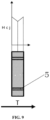
FIG. 6 is a cross-sectional side view of the Nd—Fe—B magnet block of FIG. 5 along the lines 6-6;
FIG. 7 a cross-sectional view of a gradient Nd—Fe—B magnet block taken perpendicular to a magnetization direction and illustrates coercive force distribution of the gradient Nd—Fe—B magnet segment according to one embodiment of the present invention;
FIG. 8 is a cross-sectional view of a gradient Nd—Fe—B magnet block taken at a center in the magnetization direction and illustrates coercive force distribution of an edge region of the gradient Nd—Fe—B magnet segment according to one embodiment of the present invention;
FIG. 9 is a cross-sectional view of a gradient Nd—Fe—B magnet block taken at a center in the magnetization direction and illustrates coercive force distribution of a transition region of the gradient Nd—Fe—B magnet segment according to one embodiment of the present invention;
FIG. 10 is a cross-sectional view of a gradient Nd—Fe—B magnet block taken at a center in the magnetization direction and illustrates coercive force distribution of a central region of the gradient Nd—Fe—B magnet segment according to one embodiment of the present invention;
FIG. 11 is a perspective view of a gradient Nd—Fe—B magnet having a dimension of 20 mm*20 mm*5 mm prepared according to one embodiment of the present invention;
FIG. 12 is a perspective view of a gradient Nd—Fe—B magnet having a dimension of 20 mm*1 mm*5 mm according to one embodiment of the present invention; and
FIG. 13 is a top view of the gradient Nd—Fe—B magnet of FIG. 2 including a plurality of lines for cutting the Nd—Fe—B magnet into small 1 mm*1 mm*1 mm Nd—Fe—B magnets.
DESCRIPTION OF THE ENABLING EMBODIMENT
Referring to the Figures, wherein like numerals indicate corresponding parts throughout the several views, it is one aspect of the present invention to provide a gradient Nd—Fe—B magnet. The gradient Nd—Fe—B magnet includes an Nd—Fe—B magnet block extending along a magnetization direction and having a plurality of surfaces perpendicular to the magnetization direction. According to one embodiment of the present invention, the Nd—Fe—B magnet block can have a thickness of between 2-10 mm along the magnetization direction. According to another embodiment, the Nd—Fe—B magnet block can have a length and a width of at least 10 mm.
A first film containing at least one heavy rare earth element, disposed on one of the surfaces, attaches to the Nd—Fe—B magnet block and extends along a periphery of the one of the surfaces. A second film containing at least one heavy rare earth element, disposed on another one of the surfaces, opposite of the one of the surfaces, attaches to the Nd—Fe—B magnet block and extending along a periphery of the another one of the surfaces. The at least one heavy rare earth element is selected from a group consisting of Tb, Dy, or an alloy containing Dy or Tb. Preferably, the first film and the second film are attached and formed on the Nd—Fe—B magnet block by melting a powder containing the at least one heavy rare earth metal on the one and the another one of the surfaces and along the periphery using a laser. In other words, the first film and the second film are only formed along the periphery of the one of the surfaces and the another one of the surfaces. According to one embodiment of the present invention, the powder containing the least one heavy rare earth element is selected from a group consisting of Tb, Dy, or an alloy containing Dy or Tb and is present in the powder in an amount of 0.1 wt. % and 2 wt. %. Preferably, according to one embodiment of the present invention, the powder has an average particle size of between 1 μm and 300 μm.
The first film and the second film are diffused into the Nd—Fe—B magnet block dividing the Nd—Fe—B magnet block into an edge region, a transition region, and a central region along a plane extending perpendicular to the magnetization direction. The central portion is located at the center of the Nd—Fe—B magnet block. The transition region is located about the Nd—Fe—B magnet block. The edge region is located about the transition region. In other words, the central, transition, and edge regions of the Nd—Fe—B magnet block are disposed in a concentric relationship with one another with the central regions being disposed at the center region, the transition region extending about the center region, and the edge region extending about the transition region.
The edge region has a coercivity that remains constant in a direction perpendicular to the magnetization direction, and the coercivity of the edge region, along the magnetization direction, gradually decreases from the one of the surfaces and the another one of the surfaces towards a point located between the one of the surfaces and the another one of the surfaces. The transition region also has a coercivity that decreases toward the central portion in the direction perpendicular to the magnetization direction and the coercivity of the transition region, along the magnetization direction, gradually decreases from the one of the surfaces and the another one of the surfaces to the point between the one of the surfaces and the another one of the surfaces. The center region has a coercivity that remains constant in the direction perpendicular to the magnetization direction and along the magnetization direction. It should be appreciated that an average of the coercivity of the edge region is greater than an average of the coercivity of the transition region and the average of the coercivity of the transition region is greater than an average of the coercivity of the central region. In other words, by diffusing the first film and the second film into the periphery of the Nd—Fe—B magnet block improves the coercivity of the edge portion of the Nd—Fe—B thereby improves the de-magnetization resistance of the Nd—Fe—B magnet.
It is another aspect of the present invention to provide a method of making the gradient Nd—Fe—B magnet. The method includes a first step of providing an Nd—Fe—B magnet block having a plurality of surfaces that are perpendicular to a magnetization direction. According to one embodiment of the present invention, the Nd—Fe—B magnet block can have a thickness of between 2-10 mm along the magnetization direction. According to another embodiment, the Nd—Fe—B magnet block can have a length and a width of at least 10 mm. The method then proceeds with placing the Nd—Fe—B magnet block in a chamber containing an inert gas of argon with the magnetization direction of the Nd—Fe—B magnet block being arranged in a vertical direction. The next step of the method includes depositing a powder, containing at least one heavy rare earth element, on the one of the surfaces. According to one embodiment of the present invention, the powder containing the least one heavy rare earth element is selected from a group consisting of Tb, Dy, or an alloy containing Dy or Tb and the powder is present in an amount of 0.1 wt. % and 2 wt. % of the Nd—Fe—B magnet block. Preferably, according to one embodiment of the present invention, the powder has an average particle size of between 1 μm and 300 μm.
Then, the method follows with a step of forming the first film containing the at least one heavy rare earth element on the one of the surfaces and along the periphery of the one of the surfaces. The step of forming the first film further includes a step of melting the powder on the one of the surfaces and along the periphery using a laser to form the first film and adhering the first film to the periphery. Preferably, an area covered by the first film is 10% to 65% of an area covered by the powder on one of the surfaces of the Nd—Fe—B magnet block. Next, excess powder are removed from the one of the surfaces. In other words, the powder of the heavy rare earth elements only forms the first film along the periphery of the one of the surfaces. This significantly reduces the amount of heavy rare earth elements used during the manufacturing process. After removing the excess powder, the Nd—Fe—B magnet block is rotated 180°.
After rotating the magnet block, the powder, containing at least one heavy rare earth element, is deposited on the another one of the surfaces opposite of the one of the surfaces. Then, the method proceeds with forming the second film containing the at least one heavy rare earth element on the another one of the surfaces and along the periphery of the another one of the surfaces. The step of forming the second film further including a step of melting the powder on the another one of the surfaces and along the periphery using a laser to form the second film and adhering the second film to the periphery. Preferably, an area covered by the second film is 10% to 65% of an area covered by the powder on the another one of the surfaces of the Nd—Fe—B magnet block. Next, the excess powder is removed from the another one of the surfaces. Similar to the first film, the powder of the heavy rare earth elements only forms the second film along the periphery of the another one of the surfaces. This also significantly reduces the amount of heavy rare earth elements used during the manufacturing process. Then, the first film and the second film are diffused into the Nd—Fe—B magnet block under a vacuum environment or an inert environment containing argon and at a predetermined temperature. The step of diffusing is further defined as heating the Nd—Fe—B magnet block including the first film and the second film at the predetermined temperature of between 850° C. and 950° C. at a diffusing time of between 6 hours and 72 hours. The diffusing further includes a step of aging the Nd—Fe—B magnet block including the first film and the second film at an aging temperature of between 450° C. and 650° C. at an aging time of between 3 hours and 15 hours.
The examples below provide a better illustration of the present invention. The examples are used for illustrative purposes only and do not limit the scope of the present invention.
Implementing Example 1
In implementing example 1, a plurality of Nd—Fe—B magnet blocks 1, each having a dimension of 20 mm*20 mm*5 mm are provided. Each of the Nd—Fe—B magnet blocks 1 has a plurality of surfaces that are perpendicular to a magnetization direction. Each of the Nd—Fe—B magnet blocks 1 are then placed in a chamber containing an inert gas of argon with the magnetization direction of the Nd—Fe—B magnet block 1 being arranged in a vertical direction. Then, as best illustrated in FIGS. 1 and 2 , a powder 2, containing at least one heavy rare earth element of Tb and having an average particle size of Sum, is disposed on the one of the surfaces. The heavy rare earth element is 0.5 wt. % of the total mass of the Nd—Fe—B magnet block. Next, a first film 3, as best illustrated in FIGS. 3 and 4 , containing the at least one heavy rare earth element of Tb, is formed on the one of the surfaces and along the periphery of the one of the surfaces. More specifically, the Nd—Fe—B magnet block containing the heavy rare earth element is move under a laser wherein the laser melts the powder 1, in a strip extending approximately 2 mm along the periphery of the one of the surfaces, to form the first film and adhering the first film to the periphery. The area covered by the first film is approximately 36% the area covered by the powder on one of the surfaces of the Nd—Fe—B magnet block. As best shown in FIGS. 5 and 6 , excess powder are then removed from the one of the surfaces. The Nd—Fe—B magnet block is rotated 180°.
After rotating the Nd—Fe—B magnet block, the powder 1, containing at least one heavy rare earth element of Tb, is deposited on the another one of the surfaces opposite of the one of the surfaces. A second film containing the at least one heavy rare earth element of Tb is formed on the another one of the surfaces and along the periphery of the another one of the surfaces. In particular, the Nd—Fe—B magnet block containing the heavy rare earth element is move under a laser wherein the laser melts the powder, in a strip extending approximately 2 mm along the periphery of the another one of the surfaces, to form the second film and adhering the second film to the periphery. Excess powder are then removed from the another one of the surfaces.
Then, the first film and the second film are diffused into the Nd—Fe—B magnet block under a vacuum environment and at a predetermined temperature. In particular, the Nd—Fe—B magnet block including the first film and the second film is heated at the predetermined temperature of between 900° C. at a diffusing time of 24 hours. Then, the Nd—Fe—B magnet block including the first film and the second film is subjected to an aging treatment at an aging temperature of between 500° C. at an aging time of 6 hours.
After diffusing the Nd—Fe—B magnet block, the gradient Nd—Fe—B magnet is formed and includes an edge region 4, a transition region 5, and a central region 6 along a plane extending perpendicular to the magnetization direction. The edge region 4 has a coercivity that remains constant in a direction perpendicular to the magnetization direction, and the coercivity of the edge region 4, along the magnetization direction, gradually decreases from the one of the surfaces and the another one of the surfaces towards a point located between the one of the surfaces and the another one of the surfaces. The transition region 5 also has a coercivity that decreases toward the central portion 6 in the direction perpendicular to the magnetization direction and the coercivity of the transition region 5, along the magnetization direction, gradually decreases from the one of the surfaces and the another one of the surfaces to the point located between the one of the surfaces and the another one of the surfaces. The center region 6 has a coercivity that remains constant in the direction perpendicular to the magnetization direction and along the magnetization direction. An average of the coercivity of the edge region 4 is greater than an average of the coercivity of the transition region 5 and the average of the coercivity of the transition region 6 is greater than an average of the coercivity of the central region 6.
After forming the gradient Nd—Fe—B magnet, the gradient magnet is sliced along the in the length or width direction forming a plurality of 20 mm*1 mmm*5 mm Nd—Fe—B magnets as best illustrated in FIG. 12 . Then, the Nd—Fe—B magnets are further sliced into small Nd—Fe—B magnets having a dimension of 1 mm*1 mm*1 mm as best shown in FIG. 13 . It should be noted that the Nd—Fe—B magnet located in the first row and the first column of FIG. 13 is referred to as “1, 1.” The Nd—Fe—B magnet located in the second row and the first column of FIG. 13 is referred to as “2, 1.” The Nd—Fe—B magnet located in the third row and the third column of FIG. 13 is referred to as “3, 3.” Properties of the small Nd—Fe—B magnets are then tested wherein portions of the properties are listed in Table 1 below. In addition, based on the data obtained the relationship between the coercivity and different parts of the gradient magnets are mapped and illustrated in FIGS. 7-10 .
Implementing Example 2
In implementing example 2, a plurality of Nd—Fe—B magnet blocks, each having a dimension of 40 mm*40 mm*10 mm are provided. Each of the Nd—Fe—B magnet blocks has a plurality of surfaces that are perpendicular to a magnetization direction. Each of the Nd—Fe—B magnet blocks are then placed in a chamber containing an inert gas of argon with the magnetization direction of the Nd—Fe—B magnet block being arranged in a vertical direction. Then, a powder, containing at least one heavy rare earth element of Tb and having an average particle size of 100 μm, is disposed on the one of the surfaces. The heavy rare earth element is 2.0 wt. % of the total mass of the Nd—Fe—B magnet block. Next, a first film, containing the at least one heavy rare earth element of Tb, is formed on the one of the surfaces and along the periphery of the one of the surfaces. More specifically, the Nd—Fe—B magnet block containing the heavy rare earth element is move under a laser wherein the laser melts the powder, in a strip extending approximately 3 mm along the periphery of the one of the surfaces, to form the first film and adhering the first film to the periphery. The area covered by the first film is approximately 28% the area covered by the powder on one of the surfaces of the Nd—Fe—B magnet block. Excess powder are then removed from the one of the surfaces. The Nd—Fe—B magnet block is rotated 180°.
After rotating the magnet block, the powder, containing at least one heavy rare earth element of Tb, is deposited on the another one of the surfaces opposite of the one of the surfaces. A second film containing the at least one heavy rare earth element of Tb is formed on the another one of the surfaces and along the periphery of the another one of the surfaces. In particular, the Nd—Fe—B magnet block containing the heavy rare earth element is move under a laser wherein the laser melts the powder, in a strip extending approximately 3 mm along the periphery of the another one of the surfaces, to form the second film and adhering the second film to the periphery. Excess powder are then removed from the another one of the surfaces.
Then, the first film and the second film are diffused into the Nd—Fe—B magnet block under a vacuum environment and at a predetermined temperature. In particular, the Nd—Fe—B magnet block including the first film and the second film is heated at the predetermined temperature of between 850° C. at a diffusing time of 72 hours. Then, the Nd—Fe—B magnet block including the first film and the second film is subjected to an aging treatment at an aging temperature of between 500° C. at an aging time of 15 hours.
After diffusing the Nd—Fe—B magnet block, the gradient Nd—Fe—B magnet is formed and includes an edge region, a transition region, and a central region along a plane extending perpendicular to the magnetization direction. The edge region has a coercivity that remains constant in a direction perpendicular to the magnetization direction, and the coercivity of the edge region, along the magnetization direction, gradually decreases from the one of the surfaces and the another one of the surfaces towards a point located between the one of the surfaces and the another one of the surfaces. The transition region also has a coercivity that decreases toward the central portion in the direction perpendicular to the magnetization direction and the coercivity of the transition region, along the magnetization direction, gradually decreases from the one of the surfaces and the another one of the surfaces to the point between the one of the surfaces and the another one of the surfaces. The center region has a coercivity that remains constant in the direction perpendicular to the magnetization direction and along the magnetization direction. An average of the coercivity of the edge region is greater than an average of the coercivity of the transition region and the average of the coercivity of the transition region is greater than an average of the coercivity of the central region.
After forming the gradient Nd—Fe—B magnet, the gradient magnet is sliced along the in the length or width direction forming a plurality of 40 mm*1 mmm*10 mm Nd—Fe—B magnets. Then, the Nd—Fe—B magnets are further sliced into small Nd—Fe—B magnets having a dimension of 1 mm*1 mm*1 mm. It should be noted that the Nd—Fe—B magnet located in the first row and the first column is referred to as “1, 1.” The Nd—Fe—B magnet located in the second row and the first column is referred to as “2, 1.” The Nd—Fe—B magnet located in the third row and the third column is referred to as “3, 3.” Properties of the small Nd—Fe—B magnets are then tested wherein portions of the properties are listed in Table 1 below.
Implementing Example 3
In implementing example 3, a plurality of Nd—Fe—B magnet blocks, each having a dimension of 80 mm*50 mm*5 mm are provided. Each of the Nd—Fe—B magnet blocks has a plurality of surfaces that are perpendicular to a magnetization direction. Each of the Nd—Fe—B magnet blocks are then placed in a chamber containing an inert gas of argon with the magnetization direction of the Nd—Fe—B magnet block being arranged in a vertical direction. Then, a powder, containing at least one heavy rare earth element of Dy and having an average particle size of 200 μm, is disposed on the one of the surfaces. The heavy rare earth element is 0.5 wt. % of the total mass of the Nd—Fe—B magnet block. Next, a first film, containing the at least one heavy rare earth element of Dy, is formed on the one of the surfaces and along the periphery of the one of the surfaces. More specifically, the Nd—Fe—B magnet block containing the heavy rare earth element is move under a laser wherein the laser melts the powder, in a strip extending approximately 2 mm along the periphery of the one of the surfaces, to form the first film and adhering the first film to the periphery. The area covered by the first film is approximately 24% the area covered by the powder on one of the surfaces of the Nd—Fe—B magnet block. Excess powder are then removed from the one of the surfaces. The Nd—Fe—B magnet block is rotated 180°.
After rotating the magnet block, the powder, containing at least one heavy rare earth element of Dy, is deposited on the another one of the surfaces opposite of the one of the surfaces. A second film containing the at least one heavy rare earth element of Dy is formed on the another one of the surfaces and along the periphery of the another one of the surfaces. In particular, the Nd—Fe—B magnet block containing the heavy rare earth element is move under a laser wherein the laser melts the powder, in a strip extending approximately 2 mm along the periphery of the another one of the surfaces, to form the second film and adhering the second film to the periphery. Excess powder are then removed from the another one of the surfaces.
Then, the first film and the second film are diffused into the Nd—Fe—B magnet block under a vacuum environment and at a predetermined temperature. In particular, the Nd—Fe—B magnet block including the first film and the second film is heated at the predetermined temperature of between 950° C. at a diffusing time of 6 hours. Then, the Nd—Fe—B magnet block including the first film and the second film is subjected to an aging treatment at an aging temperature of between 450° C. at an aging time of 8 hours.
After diffusing the Nd—Fe—B magnet block, the gradient Nd—Fe—B magnet is formed and includes an edge region, a transition region, and a central region along a plane extending perpendicular to the magnetization direction. The edge region has a coercivity that remains constant in a direction perpendicular to the magnetization direction, and the coercivity of the edge region, along the magnetization direction, gradually decreases from the one of the surfaces and the another one of the surfaces towards a point located between the one of the surfaces and the another one of the surfaces. The transition region also has a coercivity that decreases toward the central portion in the direction perpendicular to the magnetization direction and the coercivity of the transition region, along the magnetization direction, gradually decreases from the one of the surfaces and the another one of the surfaces to the point between the one of the surfaces and the another one of the surfaces. The center region has a coercivity that remains constant in the direction perpendicular to the magnetization direction and along the magnetization direction. An average of the coercivity of the edge region is greater than an average of the coercivity of the transition region and the average of the coercivity of the transition region is greater than an average of the coercivity of the central region.
After forming the gradient Nd—Fe—B magnet, the gradient magnet is sliced along the in the length or width direction forming a plurality of 20 mm*1 mmm*5 mm Nd—Fe—B magnets. Then, the Nd—Fe—B magnets are further sliced into small Nd—Fe—B magnets having a dimension of 1 mm*1 mm*1 mm. It should be noted that the Nd—Fe—B magnet located in the first row and the first column is referred to as “1, 1.” The Nd—Fe—B magnet located in the second row and the first column is referred to as “2, 1.” The Nd—Fe—B magnet located in the third row and the third column is referred to as “3, 3.” Properties of the small Nd—Fe—B magnets are then tested wherein portions of the properties are listed in Table 1 below.
Implementing Example 4
In implementing example 4, a plurality of Nd—Fe—B magnet blocks, each having a dimension of 80 mm*80 mm*5 mm are provided. Each of the Nd—Fe—B magnet blocks has a plurality of surfaces that are perpendicular to a magnetization direction. Each of the Nd—Fe—B magnet blocks are then placed in a chamber containing an inert gas of argon with the magnetization direction of the Nd—Fe—B magnet block being arranged in a vertical direction. Then, a powder, containing at least one heavy rare earth element of Dy and having an average particle size of 250 μm, is disposed on the one of the surfaces. The powder is an alloy powder containing Tb and Co wherein Tb is present at 90 wt. %). The powder is 0.5% of the mass of the Nd—Fe—B magnet block. Next, a first film, containing the at least one heavy rare earth element of Tb, is formed on the one of the surfaces and along the periphery of the one of the surfaces. More specifically, the Nd—Fe—B magnet block containing the heavy rare earth element is move under a laser wherein the laser melts the powder, in a strip extending approximately 2 mm along the periphery of the one of the surfaces, to form the first film and adhering the first film to the periphery. The area covered by the first film is approximately 10% the area covered by the powder on one of the surfaces of the Nd—Fe—B magnet block. Excess powder are then removed from the one of the surfaces. The Nd—Fe—B magnet block is rotated 180°.
After rotating the magnet block, the powder, containing at least one heavy rare earth element of Tb, is deposited on the another one of the surfaces opposite of the one of the surfaces. A second film containing the at least one heavy rare earth element of Tb is formed on the another one of the surfaces and along the periphery of the another one of the surfaces. In particular, the Nd—Fe—B magnet block containing the heavy rare earth element is move under a laser wherein the laser melts the powder, in a strip extending approximately 2 mm along the periphery of the another one of the surfaces, to form the second film and adhering the second film to the periphery. Excess powder are then removed from the another one of the surfaces.
Then, the first film and the second film are diffused into the Nd—Fe—B magnet block under a vacuum environment and at a predetermined temperature. In particular, the Nd—Fe—B magnet block including the first film and the second film is heated at the predetermined temperature of between 900° C. at a diffusing time of 24 hours. Then, the Nd—Fe—B magnet block including the first film and the second film is subjected to an aging treatment at an aging temperature of between 650° C. at an aging time of 6 hours.
After diffusing the Nd—Fe—B magnet block, the gradient Nd—Fe—B magnet is formed and includes an edge region, a transition region, and a central region along a plane extending perpendicular to the magnetization direction. The edge region has a coercivity that remains constant in a direction perpendicular to the magnetization direction, and the coercivity of the edge region, along the magnetization direction, gradually decreases from the one of the surfaces and the another one of the surfaces towards a point located between the one of the surfaces and the another one of the surfaces. The transition region also has a coercivity that decreases toward the central portion in the direction perpendicular to the magnetization direction and the coercivity of the transition region, along the magnetization direction, gradually decreases from the one of the surfaces and the another one of the surfaces to the point between the one of the surfaces and the another one of the surfaces. The center region has a coercivity that remains constant in the direction perpendicular to the magnetization direction and along the magnetization direction. An average of the coercivity of the edge region is greater than an average of the coercivity of the transition region and the average of the coercivity of the transition region is greater than an average of the coercivity of the central region.
After forming the gradient Nd—Fe—B magnet, the gradient magnet is sliced along the in the length or width direction forming a plurality of 80 mm*1 mmm*5 mm Nd—Fe—B magnets. Then, the Nd—Fe—B magnets are further sliced into small Nd—Fe—B magnets having a dimension of 1 mm*1 mm*1 mm. It should be noted that the Nd—Fe—B magnet located in the first row and the first column is referred to as “1, 1.” The Nd—Fe—B magnet located in the second row and the first column is referred to as “2, 1.” The Nd—Fe—B magnet located in the third row and the third column is referred to as “3, 3.” Properties of the small Nd—Fe—B magnets are then tested wherein portions of the properties are listed in Table 1 below.
Implementing Example 5
In implementing example 5, a plurality of Nd—Fe—B magnet blocks, each having a dimension of 10 mm*10 mm*2 mm are provided. Each of the Nd—Fe—B magnet blocks has a plurality of surfaces that are perpendicular to a magnetization direction. Each of the Nd—Fe—B magnet blocks are then placed in a chamber containing an inert gas of argon with the magnetization direction of the Nd—Fe—B magnet block being arranged in a vertical direction. Then, a powder, containing at least one heavy rare earth element of Tb and having an average particle size of 10 μm, is disposed on the one of the surfaces. The powder is a hydrogenated Tb powder wherein the powder is 0.1% of the mass of the Nd—Fe—B magnet blocks. Next, a first film, containing the at least one heavy rare earth element of Tb, is formed on the one of the surfaces and along the periphery of the one of the surfaces. More specifically, the Nd—Fe—B magnet block containing the heavy rare earth element is move under a laser wherein the laser melts the powder, in a strip extending approximately 2 mm along the periphery of the one of the surfaces, to form the first film and adhering the first film to the periphery. The area covered by the first film is approximately 64% the area covered by the powder on one of the surfaces of the Nd—Fe—B magnet block. Excess powder are then removed from the one of the surfaces. The Nd—Fe—B magnet block is rotated 180°.
After rotating the magnet block, the powder, containing at least one heavy rare earth element of Tb, is deposited on the another one of the surfaces opposite of the one of the surfaces. A second film containing the at least one heavy rare earth element of Tb is formed on the another one of the surfaces and along the periphery of the another one of the surfaces. In particular, the Nd—Fe—B magnet block containing the heavy rare earth element is move under a laser wherein the laser melts the powder, in a strip extending approximately 2 mm along the periphery of the another one of the surfaces, to form the second film and adhering the second film to the periphery. Excess powder are then removed from the another one of the surfaces.
Then, the first film and the second film are diffused into the Nd—Fe—B magnet block under a vacuum environment and at a predetermined temperature. In particular, the Nd—Fe—B magnet block including the first film and the second film is heated at the predetermined temperature of between 900° C. at a diffusing time of 6 hours. Then, the Nd—Fe—B magnet block including the first film and the second film is subjected to an aging treatment at an aging temperature of between 650° C. at an aging time of 3 hours.
After diffusing the Nd—Fe—B magnet block, the gradient Nd—Fe—B magnet is formed and includes an edge region, a transition region, and a central region along a plane extending perpendicular to the magnetization direction. The edge region has a coercivity that remains constant in a direction perpendicular to the magnetization direction, and the coercivity of the edge region, along the magnetization direction, gradually decreases from the one of the surfaces and the another one of the surfaces towards a point located between the one of the surfaces and the another one of the surfaces. The transition region also has a coercivity that decreases toward the central portion in the direction perpendicular to the magnetization direction and the coercivity of the transition region, along the magnetization direction, gradually decreases from the one of the surfaces and the another one of the surfaces to the point between the one of the surfaces and the another one of the surfaces. The center region has a coercivity that remains constant in the direction perpendicular to the magnetization direction and along the magnetization direction. An average of the coercivity of the edge region is greater than an average of the coercivity of the transition region and the average of the coercivity of the transition region is greater than an average of the coercivity of the central region.
Comparative Example 1
In comparative example 1, a plurality of Nd—Fe—B magnet blocks, each having a dimension of 20 mm*20 mm*5 mm are provided. More specifically, the Nd—Fe—B magnet blocks are provided using the saw raw powder as the Nd—Fe—B magnets from Implementing Example 5. The Nd—Fe—B magnet blocks are then sliced along the in the length or width direction forming a plurality of 20 mm*1 mmm*5 mm Nd—Fe—B magnets. Then, the Nd—Fe—B magnets are further sliced into small Nd—Fe—B magnets having a dimension of 1 mm*1 mm*1 mm. It should be noted that the Nd—Fe—B magnet located in the first row and the first column is referred to as “1, 1.” The Nd—Fe—B magnet located in the second row and the first column is referred to as “2, 1.” The Nd—Fe—B magnet located in the third row and the third column is referred to as “3, 3.” Properties of the small Nd—Fe—B magnets are then tested wherein portions of the properties are listed in Table 1 below.
TABLE 1
Magnetic Properties of the Gradient Magnet of Implementing Examples 1-4 and
Magnetic Properties of the Magnets of Comparative Example 1
Comparative Sample No. (1, 1) (1, 5) (1, 10) (1, 15) (1, 20)
Example Coercivity Br Hcj Br Hcj Br Hcj Br Hcj Br Hcj
13.8 18.9 13.79 18.9 13.8 18.9 13.79 18.9 13.8 18.89
Sample No. (3, 1) (3, 5) (3, 10) (3, 15) (3, 20)
Coercivity Br Hcj Br Hcj Br Hcj Br Hcj Br Hcj
13.79 18.9 13.8 18.9 13.8 18.9 13.8 18.9 13.79 18.9
Sample No. (5, 1) (5, 5) (5, 10) (5, 15) (5, 20)
Coercivity Br Hcj Br Hcj Br Hcj Br Hcj Br Hcj
13.79 18.9 13.8 18.89 13.8 18.9 13.79 18.89 13.79 18.89
Implementing Sample No. (1, 1) (1, 2) (1, 3) (1, 6) (1, 8)
Example 1 Coercivity Br Hcj Br Hcj Br Hcj Br Hcj Br Hcj
13.62 29.6 13.61 29.55 13.66 27.2 13.79 18.9 13.8 18.89
Sample No. (3, 1) (3, 2) (3, 3) (3, 6) (3, 8)
Coercivity Br Hcj Br Hcj Br Hcj Br Hcj Br Hcj
13.7 26.4 13.71 26.4 13.75 23.7 13.8 18.88 13.8 18.88
Sample No. (5, 1) (5, 2) (5, 3) (5, 6) (5, 8)
Coercivity Br Hcj Br Hcj Br Hcj Br Hcj Br Hcj
13.61 29.58 13.6 29.6 13.65 27.3 13.79 18.89 13.8 18.89
Implementing Sample No. (1, 1) (1, 3) (1, 4) (1, 8) (1, 10)
Example 2 Coercivity Br Hcj Br Hcj Br Hcj Br Hcj Br Hcj
13.59 29.58 13.6 29.55 13.65 28.1 13.79 18.88 13.8 18.9
Sample No. (5, 1) (5, 3) (5, 4) (5, 8) (5, 10)
Coercivity Br Hcj Br Hcj Br Hcj Br Hcj Br Hcj
13.71 26.42 13.73 26.38 13.76 24.2 13.8 18.89 13.79 18.89
Sample No. (10, 1) (10, 3) (10, 4) (10, 8) (10, 10)
Coercivity Br Hcj Br Hcj Br Hcj Br Hcj Br Hcj
13.6 29.57 13.61 29.58 13.66 28.2 13.79 18.9 13.8 18.88
Implementing Sample No. (1, 1) (1, 2) (1, 3) (1, 6) (1, 8)
Example 3 Coercivity Br Hcj Br Hcj Br Hcj Br Hcj Br Hcj
13.63 25.68 13.61 25.68 13.67 23.11 13.78 18.9 13.8 18.89
Sample No. (3, 1) (3, 2) (3, 3) (3, 6) (3, 8)
Coercivity Br Hcj Br Hcj Br Hcj Br Hcj Br Hcj
13.71 22.21 13.72 22.2 13.76 21.2 13.8 18.9 13.79 18.89
Sample No. (5, 1) (5, 2) (5, 3) (5, 6) (5, 8)
Coercivity Br Hcj Br Hcj Br Hcj Br Hcj Br Hcj
13.62 25.65 13.61 25.62 13.66 13.14 13.78 18.9 13.8 18.89
Implementing Sample No. (1, 1) (1, 2) (1, 3) (1, 6) (1, 8)
Example 4 Coercivity Br Hcj Br Hcj Br Hcj Br Hcj Br Hcj
13.6 29.62 13.61 29.61 13.66 27.6 13.79 18.9 13.8 18.89
Sample No. (3, 1) (3, 2) (3, 3) (3, 6) (3, 8)
Coercivity Br Hcj Br Hcj Br Hcj Br Hcj Br Hcj
13.72 26.51 13.73 26.48 13.76 23.9 13.8 18.89 13.79 18.89
Sample No. (5, 1) (5, 2) (5, 3) (5, 6) (5, 8)
Coercivity Br Hcj Br Hcj Br Hcj Br Hcj Br Hcj
13.61 26.63 13.62 29.62 13.66 27.55 13.8 18.89 13.8 18.89
As illustrated in FIG. 1 above and shown in FIGS. 7-10 , the method in accordance with the present invention effectively diffuses the heavy rare earth elements to the edge of the Nd—Fe—B magnet block thereby forming the gradient magnet including the edge portion, the transition portion, and the central portion.
Obviously, many modifications and variations of the present invention are possible in light of the above teachings and may be practiced otherwise than as specifically described while within the scope of the appended claims. These antecedent recitations should be interpreted to cover any combination in which the inventive novelty exercises its utility. The use of the word “said” in the apparatus claims refers to an antecedent that is a positive recitation meant to be included in the coverage of the claims whereas the word “the” precedes a word not meant to be included in the coverage of the claims.

Claims (20)

What is claimed is:
1. A gradient Nd—Fe—B magnet comprising:
an Nd—Fe—B magnet block extending along a magnetization direction and having a plurality of surfaces perpendicular to said magnetization direction;
a first film containing at least one heavy rare earth element, disposed on one of said surfaces, attached to said Nd—Fe—B magnet block and extending along a periphery of said one of said surfaces and wherein said first film only covers an area of 10% to 65% of said one of said surfaces; and
a second film containing at least one heavy rare earth element, disposed on another one of said surfaces, opposite of said one of said surfaces, attached to said Nd—Fe—B magnet block and extending along a periphery of said another one of said surfaces and wherein said second film only covers an area of 10% to 65% of said another one of said surfaces; and
said first film and said second film being diffused into said Nd—Fe—B magnet block dividing said Nd—Fe—B magnet block into an edge region, a transition region, and a central region along a plane extending perpendicular to said magnetization direction;
wherein said edge region has a coercivity that remains constant in a direction perpendicular to said magnetization direction, and said coercivity of said edge region, along said magnetization direction, gradually decreases from said one of said surfaces and said another one of said surfaces towards a point located between said one of said surfaces and said another one of said surfaces; and
wherein said transition region extends about said center region and said edge region extends about said transition region in concentric relationship.
2. The gradient Nd—Fe—B magnet as set forth in claim 1 wherein said transition region has a coercivity that decreases toward said central portion in said direction perpendicular to said magnetization direction and said coercivity of said transition region, along said magnetization direction, gradually decreases from said one of said surfaces and said another one of said surfaces to said point between said one of said surfaces and said another one of said surfaces.
3. The gradient Nd—Fe—B magnet as set forth in claim 1 wherein said center region has a coercivity that remains constant in said direction perpendicular to said magnetization direction and along said magnetization direction.
4. The gradient Nd—Fe—B magnet as set forth in claim 1 wherein an average of said coercivity of said edge region is greater than an average of said coercivity of said transition region and said average of said coercivity of said transition region is greater than an average of said coercivity of said central region.
5. The gradient Nd—Fe—B magnet as set forth in claim 1 wherein said Nd—Fe—B magnet block has a thickness of between 2-10 mm along said magnetization direction.
6. The gradient Nd—Fe—B magnet as set forth in claim 1 wherein said Nd—Fe—B magnet block has a length and a width of at least 10 mm.
7. The gradient Nd—Fe—B magnet as set forth in claim 1 wherein said at least one heavy rare earth element is selected from Tb, Dy, and an alloy containing Dy or Tb.
8. The gradient Nd—Fe—B magnet as set forth in claim 1 wherein said first film and said second film are attached to said Nd—Fe—B magnet block by melting a powder containing said at least one heavy rare earth metal on said one and said another one of the surfaces and along said periphery using a laser.
9. The gradient Nd—Fe—B magnet has set forth in claim 8 wherein said at least one heavy rare earth element is selected from Tb, Dy, and an alloy containing Dy or Tb and is present in said powder in an amount of 0.1 wt. % and 2 wt. %.
10. The gradient Nd—Fe—B magnet a set forth in claim 8 wherein said powder has an average particle size of between 1 μm and 300 μm.
11. The gradient Nd—Fe—B magnet a set forth in claim 8 wherein said powder melted into said first film only forms said first film along the periphery of said one of the surfaces and the excess powder not melted into said first film is removed from said one of the surfaces.
12. The gradient Nd—Fe—B magnet a set forth in claim 11 wherein said powder melted into said second film only forms said second film along the periphery of said another one of the surfaces and the excess powder not melted into said second film is removed from said another one of the surfaces.
13. A method of making the gradient Nd—Fe—B magnet of claim 1, said method including the steps of:
providing the Nd—Fe—B magnet block having a thickness of between 2-10 mm along the magnetization direction and having the surfaces perpendicular to the magnetization direction;
placing the Nd—Fe—B magnet block in a chamber containing an inert gas of argon with the magnetization direction of the Nd—Fe—B magnet block being arranged in a vertical direction;
depositing a powder, containing at least one heavy rare earth element, on the one of the surfaces;
forming the first film containing the at least one heavy rare earth element on the one of the surfaces and along the periphery of the one of the surfaces;
said step of forming the first film further including a step of melting the powder on the one of the surfaces and along the periphery using a laser to form the first film and adhering the first film to the periphery;
removing excess powder from the one of the surfaces;
rotating the Nd—Fe—B magnet block 180°;
depositing the powder, containing at least one heavy rare earth element, on the another one of the surfaces opposite of the one of the surfaces;
forming the second film containing the at least one heavy rare earth element on the another one of the surfaces and along the periphery of the another one of the surfaces;
said step of forming the second film further including a step of melting the powder on the another one of the surfaces and along the periphery using a laser to form the second film and adhering the second film to the periphery;
removing excess powder from the another one of the surfaces;
diffusing the first film and the second film into the Nd—Fe—B magnet block under a vacuum environment or an inert environment containing argon and at a predetermined temperature.
14. The method as set forth in claim 13 wherein the Nd—Fe—B magnet block has a length and a width of at least 10 mm.
15. The method as set forth in claim 13 wherein the powder has an average particle size of between 1 μm and 300 μm.
16. The method as set forth in claim 13 wherein the at least one heavy rare earth element is selected from a group consisting of Tb, Dy, or an alloy containing Dy or Tb and the powder is present in an amount of 0.1 wt. % and 2 wt. % of the total mass of the Nd—Fe—B magnet block.
17. The method as set forth in claim 13 wherein an area covered by the first film is 10% to 65% of an area covered by the powder on one of the surfaces of the Nd—Fe—B magnet block.
18. The method as set forth in claim 13 wherein an area covered by the second film is 10% to 65% of an area covered by the powder on the another one of the surfaces of the Nd—Fe—B magnet block.
19. The method set forth in claim 13 wherein said step of diffusing is further defined as heating the Nd—Fe—B magnet block including the first film and the second film at the predetermined temperature of between 850° ° C. and 950° C. at a diffusing time of between 6 hours and 72 hours.
20. The method as set forth in claim 19 wherein said step of diffusing further including a step of aging the Nd—Fe—B magnet block including the first film and the second film at an aging temperature of between 450° C. and 650° C. at an aging time of between 3 hours and 15 hours.
US16/459,448 2018-06-29 2019-07-01 Gradient Nd—Fe—B magnet and a method of production Active 2042-04-23 US12080478B2 (en)

Applications Claiming Priority (2)

Application Number Priority Date Filing Date Title
CN201810694252.7A CN108899190B (en) 2018-06-29 2018-06-29 A kind of gradient NdFeB magnet and its making method
CN201810694252.7 2018-06-29

Publications (2)

Publication Number Publication Date
US20200005996A1 US20200005996A1 (en) 2020-01-02
US12080478B2 true US12080478B2 (en) 2024-09-03

Family

ID=64347231

Family Applications (1)

Application Number Title Priority Date Filing Date
US16/459,448 Active 2042-04-23 US12080478B2 (en) 2018-06-29 2019-07-01 Gradient Nd—Fe—B magnet and a method of production

Country Status (4)

Country Link
US (1) US12080478B2 (en)
EP (1) EP3591676B1 (en)
JP (1) JP6941139B2 (en)
CN (1) CN108899190B (en)

Families Citing this family (20)

* Cited by examiner, † Cited by third party
Publication number Priority date Publication date Assignee Title
CN107424825A (en) * 2017-07-21 2017-12-01 烟台首钢磁性材料股份有限公司 A kind of neodymium iron boron magnetic body coercivity improves method
CN110133029B (en) * 2019-03-29 2021-06-18 杭州电子科技大学 A method for high-flux design of grain boundary diffuser composition in NdFeB magnets
CN110890211A (en) * 2019-12-10 2020-03-17 宁波科田磁业有限公司 Method for improving anti-demagnetization capacity of sheet magnet
KR102758091B1 (en) * 2020-04-23 2025-01-22 현대자동차주식회사 Method for manufacturing rare-earth permanent magnet and Rare-earth permanent magnet manufactured thereby
WO2021217544A1 (en) * 2020-04-30 2021-11-04 华为技术有限公司 Magnetic stabilization method for permanent magnet, magnetically stabilized permanent magnet, and permanent magnet motor
CN111653404B (en) * 2020-05-27 2022-11-15 烟台正海磁性材料股份有限公司 Neodymium-iron-boron magnet and preparation method and application thereof
CN111653407B (en) * 2020-07-20 2021-02-02 江西金力永磁科技股份有限公司 Gradient-distributed neodymium-iron-boron magnet and preparation method thereof
EP4178081A4 (en) * 2020-07-23 2023-08-16 Huawei Digital Power Technologies Co., Ltd. ROTOR FOR AN ELECTRIC MOTOR AND ELECTRIC MOTOR
CN113035556B (en) * 2021-03-04 2022-12-20 江西金力永磁科技股份有限公司 Preparation method of R-T-B magnet with gradient distribution of magnet performance
CN113096910B (en) * 2021-04-06 2022-11-25 江西金力永磁科技股份有限公司 Sheet magnet with performance in gradient distribution and preparation method thereof
KR20220146852A (en) 2021-04-26 2022-11-02 현대자동차주식회사 Divided magnet and Manufacturing method of the same
CN113808839B (en) * 2021-08-23 2022-12-16 华南理工大学 A method for preparing high coercive force NdFeB magnets by macroscopically inhomogeneous diffusion
CN114242437B (en) * 2021-11-15 2022-05-24 天津三环乐喜新材料有限公司 Preparation method of high-performance sintered Re-Fe-B system
CN115440492A (en) * 2022-08-11 2022-12-06 有研稀土(荣成)有限公司 Preparation method of high-temperature-resistant neodymium iron boron magnet and high-temperature-resistant neodymium iron boron magnet
CN119601331A (en) * 2023-09-01 2025-03-11 福建省金龙稀土股份有限公司 Neodymium iron boron magnet and its preparation method and application
CN119601330B (en) * 2023-09-01 2025-10-10 福建省金龙稀土股份有限公司 Neodymium iron boron magnet and its preparation method and application
WO2025050764A1 (en) * 2023-09-08 2025-03-13 福建省金龙稀土股份有限公司 Neodymium-iron-boron magnet, preparation method therefor and use thereof
CN118471636B (en) * 2024-06-03 2025-10-31 福建省金龙稀土股份有限公司 Neodymium-iron-boron magnet and preparation method and application thereof
CN118748112B (en) * 2024-07-10 2025-11-28 福建省金龙稀土股份有限公司 Neodymium-iron-boron magnet and preparation method and application thereof
CN119008158B (en) * 2024-09-03 2025-10-10 京磁材料科技股份有限公司 Magnetic field focusing oriented NdFeB permanent magnet and preparation method thereof

Citations (5)

* Cited by examiner, † Cited by third party
Publication number Priority date Publication date Assignee Title
US20050190031A1 (en) * 2004-02-26 2005-09-01 Shin-Etsu Chemical Co., Ltd. Sealed rare earth magnet and method for manufacturing the same
US20110068651A1 (en) * 2009-09-18 2011-03-24 Shin-Etsu Chemical Co., Ltd. Rotor for permanent magnet rotating machine
US20130002240A1 (en) * 2010-03-15 2013-01-03 Tomonari Kogure Method for determining coercivity of coercivity distribution magnet
CN106920611A (en) * 2015-12-28 2017-07-04 宁波科宁达工业有限公司 A kind of method and R-T-B series permanent magnetic materials for making high-coercive force sintering R-T-B permanent-magnet materials
US20170213626A1 (en) * 2016-01-25 2017-07-27 Ut-Battelle, Llc Neodymium-iron-boron magnet with selective surface modification, and method of producing same

Family Cites Families (15)

* Cited by examiner, † Cited by third party
Publication number Priority date Publication date Assignee Title
JPH0730362B2 (en) * 1987-03-20 1995-04-05 株式会社日立製作所 Electronic component and manufacturing method thereof
JP3943315B2 (en) * 2000-07-24 2007-07-11 松下電工株式会社 Manufacturing method of three-dimensional shaped object
ITMI20060390A1 (en) * 2006-03-03 2007-09-04 Getters Spa METHOD FOR FORMING LAYERS OF GETTER MATERIAL ON GLASS PARTS
JP4737431B2 (en) * 2006-08-30 2011-08-03 信越化学工業株式会社 Permanent magnet rotating machine
JP2010022147A (en) * 2008-07-11 2010-01-28 Hitachi Ltd Sintered magnet motor
JP2010119190A (en) * 2008-11-12 2010-05-27 Toyota Motor Corp Rotor for magnet-embedded motors and magnet-embedded motor
JP5262643B2 (en) * 2008-12-04 2013-08-14 信越化学工業株式会社 Nd-based sintered magnet and manufacturing method thereof
JP2011216836A (en) * 2010-03-17 2011-10-27 Tdk Corp Rare-earth bond magnet, method of manufacturing the same, and rotating machine
JP5406112B2 (en) * 2010-04-27 2014-02-05 インターメタリックス株式会社 Coating device for grain boundary diffusion treatment
CN101847487B (en) * 2010-06-30 2012-05-30 烟台正海磁性材料股份有限公司 Gradient coercive force neodymium iron boron magnet and production method thereof
KR101534717B1 (en) * 2013-12-31 2015-07-24 현대자동차 주식회사 Process for preparing rare earth magnets
CN106205924B (en) * 2016-07-14 2019-09-20 烟台正海磁性材料股份有限公司 A kind of preparation method of high-performance neodymium-iron-boron magnet
CN106191856B (en) * 2016-08-30 2018-11-23 安徽大地熊新材料股份有限公司 A kind of high anti-corrosion, high-coercive force Sintered NdFeB magnet and preparation method
CN107424825A (en) * 2017-07-21 2017-12-01 烟台首钢磁性材料股份有限公司 A kind of neodymium iron boron magnetic body coercivity improves method
CN108122654B (en) * 2017-12-21 2020-03-24 宁波金轮磁材技术有限公司 Grain boundary diffusion heavy rare earth NdFeB magnetic material and preparation method thereof

Patent Citations (5)

* Cited by examiner, † Cited by third party
Publication number Priority date Publication date Assignee Title
US20050190031A1 (en) * 2004-02-26 2005-09-01 Shin-Etsu Chemical Co., Ltd. Sealed rare earth magnet and method for manufacturing the same
US20110068651A1 (en) * 2009-09-18 2011-03-24 Shin-Etsu Chemical Co., Ltd. Rotor for permanent magnet rotating machine
US20130002240A1 (en) * 2010-03-15 2013-01-03 Tomonari Kogure Method for determining coercivity of coercivity distribution magnet
CN106920611A (en) * 2015-12-28 2017-07-04 宁波科宁达工业有限公司 A kind of method and R-T-B series permanent magnetic materials for making high-coercive force sintering R-T-B permanent-magnet materials
US20170213626A1 (en) * 2016-01-25 2017-07-27 Ut-Battelle, Llc Neodymium-iron-boron magnet with selective surface modification, and method of producing same

Non-Patent Citations (2)

* Cited by examiner, † Cited by third party
Title
Higashi, SAE International Journal of Alternative Powertrains, vol. 2, No. 2, p. 394-400. (Year: 2013). *
Machine translation of CN 106920611A. (Year: 2017). *

Also Published As

Publication number Publication date
CN108899190A (en) 2018-11-27
CN108899190B (en) 2020-12-22
EP3591676A1 (en) 2020-01-08
EP3591676B1 (en) 2023-06-07
US20200005996A1 (en) 2020-01-02
JP2020004969A (en) 2020-01-09
JP6941139B2 (en) 2021-09-29

Similar Documents

Publication Publication Date Title
US12080478B2 (en) Gradient Nd—Fe—B magnet and a method of production
CN111653407B (en) Gradient-distributed neodymium-iron-boron magnet and preparation method thereof
US11114237B2 (en) Method of improving the coercivity of Nd—Fe—B magnets
CN105321702B (en) One kind improves the coercitive method of sintered NdFeB magnet
Ma et al. Coercivity enhancements of Nd–Fe–B sintered magnets by diffusing DyH x along different axes
US11062844B2 (en) Method of producing R-T-B sintered magnet
JP6305916B2 (en) NdFeB-based sintered magnet
KR20140084275A (en) METHOD FOR PRODUCING NdFeB SINTERED MAGNET
EP3151252A1 (en) RFeB-BASED MAGNET AND PROCESS FOR PRODUCING RFeB-BASED MAGNET
US11315728B2 (en) Method of increasing the coercivity of a sintered Nd—Fe—B permanent magnet
WO2013100011A1 (en) Sintered neodymium magnet
JP2022023018A (en) Method for manufacturing Nd-Fe-B-based sintered magnetic material
JP6743251B2 (en) magnet
EP3425643B1 (en) Rfeb-based magnet and method for producing rfeb-based magnet
EP2450937A2 (en) Magnetic circuit for sputtering apparatus
JP5400256B1 (en) NdFeB-based sintered magnet
TW201537595A (en) Modified neodymium-iron-boron magnet and fabrication method thereof
JP7251053B2 (en) RFeB magnet and method for manufacturing RFeB magnet

Legal Events

Date Code Title Description
FEPP Fee payment procedure

Free format text: ENTITY STATUS SET TO UNDISCOUNTED (ORIGINAL EVENT CODE: BIG.); ENTITY STATUS OF PATENT OWNER: LARGE ENTITY

STPP Information on status: patent application and granting procedure in general

Free format text: DOCKETED NEW CASE - READY FOR EXAMINATION

AS Assignment

Owner name: YANTAI SHOUGANG MAGNETIC MATERIALS INC., CHINA

Free format text: ASSIGNMENT OF ASSIGNORS INTEREST;ASSIGNORS:YANG, KUNKUN;PENG, ZHONGJIE;WANG, CHUANSHEN;REEL/FRAME:051070/0286

Effective date: 20190731

STPP Information on status: patent application and granting procedure in general

Free format text: NON FINAL ACTION MAILED

STPP Information on status: patent application and granting procedure in general

Free format text: RESPONSE TO NON-FINAL OFFICE ACTION ENTERED AND FORWARDED TO EXAMINER

STPP Information on status: patent application and granting procedure in general

Free format text: NON FINAL ACTION MAILED

STPP Information on status: patent application and granting procedure in general

Free format text: RESPONSE AFTER FINAL ACTION FORWARDED TO EXAMINER

STPP Information on status: patent application and granting procedure in general

Free format text: DOCKETED NEW CASE - READY FOR EXAMINATION

STPP Information on status: patent application and granting procedure in general

Free format text: NON FINAL ACTION MAILED

STPP Information on status: patent application and granting procedure in general

Free format text: RESPONSE TO NON-FINAL OFFICE ACTION ENTERED AND FORWARDED TO EXAMINER

STPP Information on status: patent application and granting procedure in general

Free format text: NOTICE OF ALLOWANCE MAILED -- APPLICATION RECEIVED IN OFFICE OF PUBLICATIONS

STPP Information on status: patent application and granting procedure in general

Free format text: PUBLICATIONS -- ISSUE FEE PAYMENT RECEIVED

STCF Information on status: patent grant

Free format text: PATENTED CASE