US12078262B2 - Operation valve - Google Patents
Operation valve Download PDFInfo
- Publication number
- US12078262B2 US12078262B2 US18/084,176 US202218084176A US12078262B2 US 12078262 B2 US12078262 B2 US 12078262B2 US 202218084176 A US202218084176 A US 202218084176A US 12078262 B2 US12078262 B2 US 12078262B2
- Authority
- US
- United States
- Prior art keywords
- valve
- dial
- operation dial
- housing body
- urea water
- Prior art date
- Legal status (The legal status is an assumption and is not a legal conclusion. Google has not performed a legal analysis and makes no representation as to the accuracy of the status listed.)
- Active, expires
Links
Images


Classifications
-
- F—MECHANICAL ENGINEERING; LIGHTING; HEATING; WEAPONS; BLASTING
- F16—ENGINEERING ELEMENTS AND UNITS; GENERAL MEASURES FOR PRODUCING AND MAINTAINING EFFECTIVE FUNCTIONING OF MACHINES OR INSTALLATIONS; THERMAL INSULATION IN GENERAL
- F16K—VALVES; TAPS; COCKS; ACTUATING-FLOATS; DEVICES FOR VENTING OR AERATING
- F16K3/00—Gate valves or sliding valves, i.e. cut-off apparatus with closing members having a sliding movement along the seat for opening and closing
- F16K3/22—Gate valves or sliding valves, i.e. cut-off apparatus with closing members having a sliding movement along the seat for opening and closing with sealing faces shaped as surfaces of solids of revolution
- F16K3/24—Gate valves or sliding valves, i.e. cut-off apparatus with closing members having a sliding movement along the seat for opening and closing with sealing faces shaped as surfaces of solids of revolution with cylindrical valve members
- F16K3/26—Gate valves or sliding valves, i.e. cut-off apparatus with closing members having a sliding movement along the seat for opening and closing with sealing faces shaped as surfaces of solids of revolution with cylindrical valve members with fluid passages in the valve member
- F16K3/262—Gate valves or sliding valves, i.e. cut-off apparatus with closing members having a sliding movement along the seat for opening and closing with sealing faces shaped as surfaces of solids of revolution with cylindrical valve members with fluid passages in the valve member with a transverse bore in the valve member
-
- F—MECHANICAL ENGINEERING; LIGHTING; HEATING; WEAPONS; BLASTING
- F16—ENGINEERING ELEMENTS AND UNITS; GENERAL MEASURES FOR PRODUCING AND MAINTAINING EFFECTIVE FUNCTIONING OF MACHINES OR INSTALLATIONS; THERMAL INSULATION IN GENERAL
- F16K—VALVES; TAPS; COCKS; ACTUATING-FLOATS; DEVICES FOR VENTING OR AERATING
- F16K31/00—Actuating devices; Operating means; Releasing devices
- F16K31/44—Mechanical actuating means
- F16K31/50—Mechanical actuating means with screw-spindle or internally threaded actuating means
- F16K31/508—Mechanical actuating means with screw-spindle or internally threaded actuating means the actuating element being rotatable, non-rising, and driving a non-rotatable axially-sliding element
-
- F—MECHANICAL ENGINEERING; LIGHTING; HEATING; WEAPONS; BLASTING
- F16—ENGINEERING ELEMENTS AND UNITS; GENERAL MEASURES FOR PRODUCING AND MAINTAINING EFFECTIVE FUNCTIONING OF MACHINES OR INSTALLATIONS; THERMAL INSULATION IN GENERAL
- F16K—VALVES; TAPS; COCKS; ACTUATING-FLOATS; DEVICES FOR VENTING OR AERATING
- F16K27/00—Construction of housing; Use of materials therefor
- F16K27/04—Construction of housing; Use of materials therefor of sliding valves
- F16K27/041—Construction of housing; Use of materials therefor of sliding valves cylindrical slide valves
-
- F—MECHANICAL ENGINEERING; LIGHTING; HEATING; WEAPONS; BLASTING
- F16—ENGINEERING ELEMENTS AND UNITS; GENERAL MEASURES FOR PRODUCING AND MAINTAINING EFFECTIVE FUNCTIONING OF MACHINES OR INSTALLATIONS; THERMAL INSULATION IN GENERAL
- F16K—VALVES; TAPS; COCKS; ACTUATING-FLOATS; DEVICES FOR VENTING OR AERATING
- F16K3/00—Gate valves or sliding valves, i.e. cut-off apparatus with closing members having a sliding movement along the seat for opening and closing
- F16K3/22—Gate valves or sliding valves, i.e. cut-off apparatus with closing members having a sliding movement along the seat for opening and closing with sealing faces shaped as surfaces of solids of revolution
- F16K3/24—Gate valves or sliding valves, i.e. cut-off apparatus with closing members having a sliding movement along the seat for opening and closing with sealing faces shaped as surfaces of solids of revolution with cylindrical valve members
- F16K3/26—Gate valves or sliding valves, i.e. cut-off apparatus with closing members having a sliding movement along the seat for opening and closing with sealing faces shaped as surfaces of solids of revolution with cylindrical valve members with fluid passages in the valve member
-
- F—MECHANICAL ENGINEERING; LIGHTING; HEATING; WEAPONS; BLASTING
- F16—ENGINEERING ELEMENTS AND UNITS; GENERAL MEASURES FOR PRODUCING AND MAINTAINING EFFECTIVE FUNCTIONING OF MACHINES OR INSTALLATIONS; THERMAL INSULATION IN GENERAL
- F16K—VALVES; TAPS; COCKS; ACTUATING-FLOATS; DEVICES FOR VENTING OR AERATING
- F16K31/00—Actuating devices; Operating means; Releasing devices
- F16K31/44—Mechanical actuating means
- F16K31/50—Mechanical actuating means with screw-spindle or internally threaded actuating means
Definitions
- the present disclosure relates to an operation valve.
- a urea water tank for storing the above-described urea water is also known.
- a screw hole and a drain plug for discharging urea water are provided in a lower surface portion of the urea water tank.
- urea water in the urea water tank is discharged (see, for example, WO 2018/179342). It is known that urea water freezes at around ⁇ 10 Celsius degrees (see, for example, Japanese Unexamined Patent Application Publication No. 2003-020936).
- urea water tank When a urea water tank is mounted on a large construction machine, a large urea water tank that stores 30 to 150 L (liters) of urea water is often mounted.
- the quality check of urea water stored in such a urea water tank is performed, if the drain plug is removed, a large amount of urea water is ejected, which is inconvenient for the quality check.
- an operation valve may be attached to the urea water tank instead of the drain plug.
- the operation valve adjusts the flow rate of urea water.
- an operation valve provided with a valve chamber housing a ball valve which is a spherical valve body is known (see, for example, Japanese Unexamined Utility Model Application Publication No. 5-083560).
- the ball valve when the ball valve is closed, liquid accumulates in the valve chamber.
- An object of the present disclosure is to provide an operation valve comprising: a valve formed into a rod shape and including a barrel portion in which a flow path for a fluid is provided, a head portion in which an inlet of the flow path is provided, and a leg portion in which an outlet of the flow path is provided; a housing body housing the barrel portion; and an operation dial screw coupled to the housing body and moving the valve in an extension direction of the valve.
- FIG. 1 A is a first perspective view illustrating an example of a valve closed state of an operation valve according to a first embodiment attached to a bottom wall of a urea water tank;
- FIG. 1 B is a second perspective view illustrating an example of the valve closed state of the operation valve according to the first embodiment attached to the bottom wall of the urea water tank;
- FIG. 1 C is a cross-sectional view taken along a line Z 1 -Z 1 and illustrating an example of the valve closed state of the operation valve according to the first embodiment attached to the bottom wall of the urea water tank;
- FIG. 2 A is an example of an exploded perspective view of the operation valve according to the first embodiment
- FIG. 2 B is an example of an exploded cross-sectional view, taken along a line Z 2 -Z 2 , of the operation valve according to the first embodiment;
- FIG. 3 A is a perspective view illustrating an example of the valve closed state of the operation valve according to the first embodiment
- FIG. 3 B is a cross-sectional view taken along a line Z 3 -Z 3 and illustrating an example of the valve closed state of the operation valve according to the first embodiment
- FIG. 4 A is a first perspective view illustrating an example of a valve open state of the operation valve according to the first embodiment attached to the bottom wall of the urea water tank;
- FIG. 4 B is a second perspective view illustrating an example of the valve open state of the operation valve according to the first embodiment attached to the bottom wall of the urea water tank;
- FIG. 4 C is a cross-sectional view taken along a line Z 4 -Z 4 and illustrating an example of the valve open state of the operation valve according to the first embodiment attached to the bottom wall of the urea water tank;
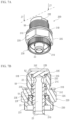
- FIG. 5 A is a first perspective view illustrating an example of a valve closed state of the operation valve according to a second embodiment attached to the bottom wall of the urea water tank;
- FIG. 5 B is a second perspective view illustrating an example of the valve closed state of the operation valve according to the second embodiment attached to the bottom wall of the urea water tank;
- FIG. 5 C is a cross-sectional view taken along a line Z 5 -Z 5 and illustrating an example of the valve closed state of the operation valve according to the second embodiment attached to the bottom wall of the urea water tank;
- FIG. 6 A is an example of an exploded perspective view of the operation valve according to the second embodiment
- FIG. 6 B is an example of an exploded cross-sectional view, taken along a line Z 6 -Z 6 , of the operation valve according to the second embodiment;
- FIG. 7 A is a perspective view illustrating an example of the valve closed state of the operation valve according to the second embodiment
- FIG. 7 B is a cross-sectional view taken along a line Z 7 -Z 7 and illustrating an example of the valve closed state of the operation valve according to the second embodiment
- FIG. 8 A is a first perspective view illustrating an example of a valve open state of the operation valve according to the second embodiment attached to the bottom wall of the urea water tank;
- FIG. 8 B is a second perspective view illustrating an example of the valve open state of the operation valve according to the second embodiment attached to the bottom wall of the urea water tank;
- FIG. 8 C is a cross-sectional view taken along a line Z 8 -Z 8 and illustrating an example of the valve open state of the operation valve according to the second embodiment attached to the bottom wall of the urea water tank.
- an operation valve 100 is attached to a drain port 11 provided in a bottom wall 10 of a urea water tank.
- FIGS. 1 A to 1 C illustrate a part of the bottom wall 10 of the urea water tank.
- the urea water tank is a container for storing urea water.
- the drain port 11 is an opening for discharging urea water stored in the urea water tank.
- Urea water is an example of the fluid and is an aqueous solution in which urea is dissolved in water. Urea water is used as a reducing agent for purifying NOx in exhaust gas from a diesel engine mounted on a construction machine, a transport vehicle, or the like.
- a female screw S 1 is provided on the inner circumference of the drain port 11 .
- the operation valve 100 includes a valve (hereinafter referred to as a stick valve) 110 having a rod shape, a valve body 120 , an operation dial 130 , and a protective cap 140 .
- the valve body 120 is an example of a housing body, and houses a trunk portion of the stick valve 110 .
- a male screw S 2 is provided on the outer peripheral surface of the distal end portion of the valve body 120 .
- the male screw S 2 is screw coupled with the female screw S 1 of the drain port 11 .
- the operation valve 100 is mechanically attached to the bottom wall 10 of the urea water tank.
- the operation valve 100 will be described in detail with reference to FIG. 2 .
- the stick valve 110 integrally includes a barrel portion 111 , a head portion 112 , and a leg portion 113 .
- the head portion 112 is located directly above the barrel portion 111 .
- the leg portion 113 is located immediately below the barrel portion 111 . That is, the barrel portion 111 is sandwiched between the head portion 112 and the leg portion 113 .
- the stick valve 110 has a cylindrical shape.
- a flow path 21 for urea water is provided inside the barrel portion 111 . As will be described in detail later, the flow path 21 is also provided inside the leg portion 113 . The flow path 21 extends in the same direction as the extension direction of the stick valve 110 .
- a ring groove 21 B circulating in the circumferential direction is provided on a barrel side surface 21 A located at the front end of the barrel portion 111 .
- An O-ring 21 C is attached to the ring groove 21 B.
- the O-ring 21 C is an example of a first sealing ring, and seals the valve body 120 from urea water.
- the O-ring 21 C makes it difficult for urea water to enter the valve body 120 .
- the rear end of the barrel portion 111 has an outer diameter smaller than an outer diameter of the front end of the barrel portion 111 . That is, there is a step 51 between the rear end of the barrel portion 111 and the front end of the barrel portion 111 .
- the step 51 may be the same as or different from the ring groove 21 B in depth.
- the head portion 112 is provided with an inlet 22 of the flow path 21 .
- the inlet 22 is provided on a head side surface 22 A of the head portion 112 .
- the head side surface 22 A is provided with a ring groove 22 B extending in the circumferential direction.
- An O-ring 22 C is attached to the ring groove 22 B.
- the O-ring 22 C is an example of a second sealing ring, and seals the valve body 120 from urea water.
- the two O-rings 21 C and 22 C make it difficult for urea water to enter the inside of the valve body 120 . That is, it is possible to prevent or suppress the infiltration of urea water into the valve body 120 .
- a canopy portion 22 D having a disc shape is provided at the front end of the head portion 112 .
- the canopy portion 22 D has an outer diameter that is greater than the outer diameter of the rear end of the head portion 112 . Therefore, there is a step 52 between the front end of the head portion 112 and the rear
- the flow path 21 of the barrel portion 111 extends inside the leg portion 113 .
- the side surface of the leg portion 113 is continuous to the side surface of the rear end of the barrel portion 111 without a step.
- An outlet 23 of the flow path 21 is provided on a bottom surface of the leg portion 113 .
- a ring groove 23 B extending in the circumferential direction is provided in a leg side surface 23 A located at the rear end of the leg portion 113 .
- a C-ring 23 C is attached to the ring groove 23 B.
- the C-ring 23 C is an example of a coupling ring, and couples the leg portion 113 and the operation dial 130 .
- the valve body 120 integrally includes a valve housing portion 121 and a dial housing portion 122 .
- the valve housing portion 121 has a first cavity portion 31 A having a cylindrical shape and extending in the same direction as the central axis direction of the valve body 120 . That is, the valve housing portion 121 has a cylindrical shape.
- the valve housing portion 121 has a partition wall 31 B that separates the inside and the outside of the valve housing portion 121 .
- the inside diameter of the partition wall 31 B is substantially the same as the outside diameter of the barrel side surface 21 A. Therefore, the barrel portion 111 of the stick valve 110 is inserted into the first cavity portion 31 A.
- a male screw S 2 is provided at the front end of the outer peripheral surface of the partition wall 31 B. As described above, the male screw S 2 is screw coupled to the female screw S 1 of the drain port 11 .
- a gasket mounting portion 31 C is provided at the rear end of the partition wall 31 B.
- a gasket 31 D having a ring shape is mounted on the gasket mounting portion 31 C. Accordingly, it is possible to suppress leakage of urea water when the operation valve 100 is attached to the urea water tank.
- an O-ring may be used instead of the gasket 31 D.
- the inside of the dial housing portion 122 has a second cavity portion 32 A and a third cavity portion 32 D each having a cylindrical shape extending in the same direction as the central axis direction of the valve body 120 .
- the third cavity portion 32 D is located at the distal end of the dial housing portion 122 . That is, the third cavity portion 32 D is located immediately below the first cavity portion 31 A.
- the second cavity portion 32 A has an inside diameter greater than an inside diameter of the first cavity portion 31 A.
- the third cavity portion 32 D has an inside diameter greater than an inside diameter of the second cavity portion 32 A. Therefore, the third cavity portion 32 D has the inside diameter greater than the inside diameter of the first cavity portion 31 A.
- the dial housing portion 122 has a cylindrical shape. For this reason, the dial housing portion 122 has a partition wall 32 B that separates the inside and the outside of the dial housing portion 122 . Since the third cavity portion 32 D has an inner diameter larger than that of the first cavity portion 31 A, there is a step 53 between the partition wall 32 B of the dial housing portion 122 and the partition wall 31 B of the valve housing portion 121 .
- a female screw S 3 is provided on an inner peripheral surface of the partition wall 32 B so as to extend circumferentially.
- a bolt portion 32 C having a hexagonal shape is provided integrally with the partition wall 32 B at a partition wall central portion located between the front end and the rear end of the partition wall 32 B.
- the valve body 120 is attached to the bottom wall 10 of the urea water tank by holding the bolt portion 32 C with two fingers and rotating the valve body 120 clockwise. If necessary, the bolt portion 32 C may be gripped by a tool such as a hexagonal spanner to rotate the valve body 120 clockwise.
- the inside of the operation dial 130 includes a fourth cavity portion 41 A having a cylindrical shape extending in the same direction as the central axis direction of the operation dial 130 . That is, the shape of the operation dial 130 is cylindrical. For this reason, the operation dial 130 has a partition wall 41 B that separates the inside and the outside of the operation dial 130 .
- the inner peripheral surface of the partition wall 41 B has the same inside diameter at one end and the other end. That is, the fourth cavity portion 41 A has the same inside diameter from one end to the other end.
- the rear end of the barrel portion 111 and the leg portion 113 of the stick valve 110 are inserted into the fourth cavity portion 41 A.
- the outer diameters of the rear end of the barrel portion 111 and the outer peripheral surface of the leg portion 113 of the stick valve 110 are substantially the same as the inside diameter of the inner peripheral surface of the partition wall 41 B.
- the outer peripheral surface of the partition wall 41 B has different outer diameters at one end and the other end.
- One end of the partition wall 41 B has an outer diameter greater than the outer diameter of the other end of the partition wall 41 B.
- the partition wall 41 B has a step 54 on the outer peripheral surface.
- the outside diameter of the partition wall 41 B is substantially the same as the inside diameter of the partition wall 32 B of the dial housing portion 122 .
- a male screw S 4 is provided at one end of the outer peripheral surface of the partition wall 41 B. Therefore, one end of the operation dial 130 is screw coupled to the second cavity portion 32 A of the valve body 120 .
- the outer peripheral surface of the other end of the operation dial 130 includes a pair of curved surfaces 41 C facing each other and a pair of flat surfaces 41 D facing each other.
- the screw connection between the valve body 120 and the operation dial 130 is tightened or loosened by holding the pair of flat surfaces between two fingers and rotating the operation dial 130 .
- the protective cap 140 is a cap that protects the dial side surface and the dial bottom surface of the operation dial 130 from adhesion of foreign matter or water droplets.
- the foreign matter includes, for example, sand and dust. Examples of the water droplets include urea water and rainwater. When the foreign matter adheres, there is a possibility that the rotation of the operation dial 130 becomes difficult. In addition, even if the water droplets adhere and freeze, there is a possibility that the rotation of the operation dial 130 becomes difficult.
- the protective cap 140 prevents the operation dial 130 from being exposed, and suppresses adhesion of foreign matter and water droplets. As a result, the operability of the operation dial 130 is improved.
- the protective cap 140 also prevents the operation dial 130 from being damaged by contact with a tool, for example.
- a long hole portion 61 A having a columnar shape and extending in the same direction as the central axis direction of the protective cap 140 is provided inside the protective cap 140 .
- the shape of the protective cap 140 is a bottomed cylinder.
- the rear end of the operation dial 130 is housed in the long hole portion 61 A.
- An O-ring 61 B is disposed on the inner bottom of the protective cap 140 .
- the O-ring 61 B abuts a leg bottom wall 23 D of the operation dial 130 located around the outlet 23 (see also FIG. 1 C ).
- the O-ring 61 B prevents direct contact between the leg bottom wall 23 D of the operation dial 130 and the protective cap 140 . Thus, damage to the protective cap 140 caused by the operation dial 130 is suppressed.
- the inside diameter on the opening side of the protective cap 140 is substantially the same as the outside diameter of the partition wall 41 B of the operation dial 130 .
- a female screw S 5 extending in the circumferential direction is provided on the inner circumference of the opening side of the protective cap 140 .
- the female screw S 5 of the protective cap 140 is screw coupled to the male screw S 4 of the operation dial 130 . Therefore, the protective cap 140 is attached to and detached from the operation dial 130 . In other words, the protective cap 140 is removed from the operation dial 130 and is attached to the operation dial 130 . Since the male screw S 4 of the operation dial 130 is screw coupled not only to the female screw S 5 of the protective cap 140 but also to the female screw S 3 of the valve body 120 , the male screw S 4 is shared by the female screws S 3 and S 5 .
- the operation dial 130 is partially exposed as illustrated in FIGS. 3 A and 3 B .
- the protective cap 140 is removed from the operation dial 130 by being rotated counterclockwise in the circumferential direction.
- the step 52 (also see FIG. 2 B ) of the canopy portion 22 D in the stick valve 110 is in contact with the partition wall 31 B of the valve body 120 , and the inlet 22 of the stick valve 110 disappears into the valve body 120 .
- the inlet 22 is closed by the valve body 120 , urea water is prevented from flowing into the flow path 21 . That is, when the inlet 22 disappears into the valve body 120 , the operation valve 100 is closed. There is little possibility that urea water enters the inside of the valve body 120 from the contact surface between the canopy portion 22 D and the partition wall 31 B.
- the O-ring 22 C prevents urea water from entering the inside of the valve body 120 (specifically, the inlet 22 ). In this way, when the operation valve 100 is closed, the inflow of urea water from the urea water tank to the inside of the operation valve 100 is stopped.
- the connection between the stick valve 110 and the operation dial 130 is maintained by the C-ring 23 C, whereby the step 51 of the stick valve 110 (see also FIG. 2 B ) and the top surface of the partition wall 41 B of the operation dial 130 come into contact with each other.
- the relative positional relationship between the stick valve 110 and the operation dial 130 is maintained by the connection by the C-ring 23 C and the contact between the stick valve 110 and the operation dial 130 .
- the stick valve 110 is interlocked with the movement of the operation dial 130 .
- the operation dial 130 pushes up the stick valve 110 by the upward movement of the operation dial 130 . That is, the operation dial 130 drives the stick valve 110 in the extension direction of the stick valve 110 .
- the canopy portion 22 D of the stick valve 110 is separated from the partition wall 31 B of the valve body 120 , and the inlet 22 appears.
- urea water flows into the inlet 22 , flows through the flow path 21 , and flows out from the outlet 23 .
- the upward movement of the operation dial 130 is stopped when the top surface of the partition wall 41 B of the operation dial 130 comes into contact with the step 53 of the valve body 120 (see also FIG. 2 B ).
- the operation dial 130 moves while rotating, the stick valve 110 linearly moves independently of the rotation of the operation dial 130 . Accordingly, it is possible to suppress deterioration of the two O-rings 21 C and 22 C attached to the stick valve 110 .
- valve open state can be transitioned to the valve closed state by performing the series of flows in reverse.
- the operation dial 130 when the operation dial 130 is rotated counterclockwise in the circumferential direction, the screw fastening between the female screw S 3 of the valve body 120 and the male screw S 4 of the operation dial 130 is loosened, and the operation dial 130 is lowered while rotating in a direction away from urea water tank. Since the operation dial 130 is connected to the stick valve 110 via the C-ring 23 C, when the operation dial 130 is lowered, the stick valve 110 is also lowered. That is, the operation dial 130 moves the stick valve 110 in a direction in which the inlet 22 disappears into the valve body 120 via the C-ring 23 C.
- the inlet 22 appears or disappears from the valve body 120 in accordance with the movement of the operation dial 130 .
- the inlet 22 appears and disappears from the valve body 120 in accordance with the movement of the operation dial 130 .
- the ball valve is excluded from the operation valve 100 according to the first embodiment. In this way, even if there is a possibility that urea water freezes, it is possible to provide the operation valve 100 with a simple structure in which the ball valve is excluded with respect to freezing of urea water.
- FIGS. 5 A to 8 C Components similar to those of the operation valve 100 described in the first embodiment are denoted by the same or corresponding reference numerals, and description thereof will be omitted.
- an operation valve 200 is also attached to the drain port 11 provided in the bottom wall 10 of the urea water tank, similarly to the first embodiment.
- the operation valve 200 includes a stick valve 210 , a valve body 220 , and an operation dial 230 .
- the valve body 220 is an example of a housing body, and houses a trunk portion of the stick valve 210 .
- a male screw S 6 is provided on the outer peripheral surface of the distal end portion of the valve body 220 .
- the male screw S 6 is screw coupled with the female screw S 1 of the drain port 11 .
- the operation valve 200 can be mechanically attached to the bottom wall 10 of the urea water tank.
- the operation valve 200 will be described in detail with reference to FIGS. 6 A to 6 C .
- the stick valve 210 integrally includes a barrel portion 211 , a head portion 212 , and a leg portion 213 .
- the head portion 212 is located directly above the barrel portion 211 .
- the leg portion 213 is located immediately below the barrel portion 211 . That is, the barrel portion 211 is sandwiched between the head portion 212 and the leg portion 213 .
- the shape of the stick valve 210 is cylindrical except for a part of the head portion 212 .
- the flow path 21 for urea water is provided inside the barrel portion 211 .
- the flow path 21 is also provided inside the leg portion 213 .
- the flow path 21 extends in the same direction as the extension direction of the stick valve 210 .
- the ring groove 21 B circulating in the circumferential direction is provided on the barrel side surface 21 A located at the front end of the barrel portion 211 .
- the O-ring 21 C is attached to the ring groove 21 B.
- the O-ring 21 C is an example of a first sealing ring, and seals the valve body 220 from urea water.
- the O-ring 21 C makes it difficult for urea water to enter the valve body 220 .
- the rear end of the barrel portion 211 has an outer diameter smaller than an outer diameter of the front end of the barrel portion 211 . That is, there is the step 51 between the rear end of the barrel portion 211 and the front end of the barrel portion 211 .
- the head portion 212 is provided with the inlet 22 of the flow path 21 .
- the inlet 22 is provided on the head side surface 22 A of the head portion 212 .
- the head side surface 22 A is provided with the ring groove 22 B extending in the circumferential direction.
- the O-ring 22 C is attached to the ring groove 22 B.
- the O-ring 22 C is an example of a second sealing ring, and seals the valve body 220 from urea water.
- the two O-rings 21 C and 22 C make it extremely difficult for urea water to enter the inside of the valve body 220 . That is, it is possible to prevent or suppress the infiltration of urea water into the valve body 220 .
- the canopy portion 22 D having a disc shape is provided at the front end of the head portion 212 .
- the canopy portion 22 D has an outer diameter that is greater than the outer diameter of the rear end of the head portion 212 . Therefore, there is the step 52 between the front end of the head portion 112 and the rear end of the head portion 112 .
- the canopy portion 22 D according to the second embodiment is integrally provided with two overhanging portions 22 E facing each other with respect to the center of the canopy portion 22 D. Therefore, the step 52 is continuous from the canopy portion 22 D to the overhanging portion 22 E. Both side surfaces of the two overhanging portions 22 E are curved in an arc shape, and the thicknesses of the two overhanging portions 22 E are the same as the thicknesses of the canopy portion 22 D. As will be described in detail later, the two overhanging portions 22 E are housed between two arc walls 31 E provided at the distal end of the valve body 220 so as to be spaced apart from each other.
- the flow path 21 of the barrel portion 211 extends inside the leg portion 213 .
- a protrusion 23 E having the same outer diameter as the outer diameter of the barrel side surface 21 A is provided on the front end side surface of the leg portion 213 . Therefore, the side surface of the leg portion 213 is not flatly continuous to the side surface of the rear end of the barrel portion 211 .
- the outlet 23 of the flow path 21 is provided on a bottom surface of the leg portion 213 .
- a male screw S 7 extending in the circumferential direction is provided on the leg side surface 23 A of the leg portion 213 located between the protrusion 23 E and the outlet 23 . Although the details will be described later, the male screw S 7 is screw coupled to a female screw S 8 provided inside the operation dial 230 .
- the valve body 220 integrally includes a valve housing portion 221 and a dial housing portion 222 .
- the valve housing portion 221 has the first cavity portion 31 A having a cylindrical shape and extending in the same direction as the central axis direction of the valve body 220 . That is, the valve housing portion 221 has a cylindrical shape.
- the valve housing portion 221 has the partition wall 31 B that separates the inside and the outside of the valve housing portion 221 .
- the inside diameter of the partition wall 31 B is substantially the same as the outside diameters of the barrel side surface 21 A and the protrusion 23 E. Therefore, the barrel portion 211 of the stick valve 210 can be inserted into the first cavity portion 31 A.
- a tapered surface 31 G is provided on the inner peripheral surface located at the front end of the partition wall 31 B.
- the two walls 31 E each having an arc shape are provided on the top surface located at the front end of the partition wall 31 B.
- the extension direction of the two arc walls 31 E is the same as the extension direction of the valve body 220 .
- the two arc walls 31 E are equally spaced apart in the circumferential direction. Therefore, there are two gaps between the two arc walls 31 E.
- One of the two overhanging portions 22 E described above is housed in one of the gaps, and the other of the two overhanging portions 22 E described above is housed in the other of the gaps.
- the gasket mounting portion 31 C is provided at the rear end of the partition wall 31 B.
- the gasket 31 D having a ring shape is mounted on the gasket mounting portion 31 C. Accordingly, it is possible to suppress leakage of urea water when the operation valve 100 is attached to the urea water tank.
- a ring groove 31 F is provided on the inner peripheral surface of the rear end of the partition wall 31 B.
- a C-ring 23 G is attached to the ring groove 31 F. As will be described in detail later, the C-ring 23 G restricts the amount of movement of the stick valve 210 .
- By regulating the amount of movement of the stick valve 210 it is possible to accurately control the integral movement of the canopy portion 22 D and the overhanging portion 22 E of the stick valve 210 . In other words, opening and closing of the stick valve 210 can be controlled with high accuracy.
- the inside of the dial housing portion 222 includes the second cavity portion 32 A and a fifth cavity portion 32 E each having a columnar shape extending in the same direction as the central axis direction of the valve body 220 .
- the fifth cavity portion 32 E is located at the distal end of the dial housing portion 222 .
- the fifth cavity portion 32 E is continuous with the first cavity portion 31 A located below the ring groove 31 F. That is, the fifth cavity portion 32 E is located immediately below the first cavity portion 31 A.
- the outer diameter of the fifth cavity portion 32 E is the same as the outer diameter of the first cavity portion 31 A.
- the second cavity portion 32 A has an outer diameter greater than an outer diameter of the fifth cavity portion 32 E.
- the dial housing portion 222 has a cylindrical shape. For this reason, the dial housing portion 222 has the bolt portion 32 C that separates the inside and the outside of the dial housing portion 222 .
- the bolt portion 32 C is provided integrally with the partition wall 31 B. Since the second cavity portion 32 A has a larger outer diameter than the fifth cavity portion 32 E, there is a step 55 between the bolt portion 32 C of the dial housing portion 222 and the partition wall 31 B of the valve housing portion 221 .
- the valve body 220 can be attached to the bottom wall 10 of the urea water tank by holding the bolt portion 32 C with two fingers and rotating the valve body 220 clockwise.
- the inner circumferential surface of the bolt portion 32 C corresponding to the second cavity portion 32 A is provided with a ring groove 32 F extending in the circumferential direction.
- a C-ring 23 F is attached to the ring groove 32 F. As will be described in detail later, the C-ring 23 F fixes the position of the operation dial 230 and restricts operations other than the rotation of the operation dial 230 .
- the operation dial 230 includes a coupling portion 231 having a bottomless cylindrical shape.
- the operation dial 230 includes an operation portion 232 having a bottomed cylindrical shape and extending in the same direction as the extension direction of the stick valve 210 .
- the operation dial 230 integrally includes the coupling portion 231 and the operation portion 232 .
- the coupling portion 231 and the operation portion 232 have different outer diameters. Specifically, the outer diameter of the coupling portion 231 is smaller than the outer diameter of the operation portion 232 .
- the coupling portion 231 and the operation portion 232 have different inner diameters. Specifically, the inner diameter of the coupling portion 231 is smaller than the inner diameter of the rear end side of the operation portion 232 .
- the inner diameter of the distal end side of the operation portion 232 is the same as the inner diameter of the coupling portion 231 .
- the operation portion 232 has a bottom portion formed into a disc shape and having an opening at a central portion thereof.
- the coupling portion 231 may be coupled to the dial housing portion 222 .
- the operation portion 232 is operated to open and close the stick valve 210 .
- the stick valve 210 can be opened or closed by holding the operation portion 232 between two fingers and rotating it clockwise or counterclockwise.
- a female screw S 8 is provided on an inner peripheral surface of the coupling portion 231 .
- a female screw S 8 is also provided on the inner peripheral surface of the distal end side of the operation portion 232 .
- the leg portion 213 of the stick valve 210 is partially inserted into the coupling portion 231 and the operation portion 232 , and the male screw S 7 of the leg portion 213 is screw coupled to the female screw S 8 of the coupling portion 231 and the operation portion 232 .
- a ring groove 41 E is provided on the outer peripheral surface of the coupling portion 231 .
- the C-ring 23 F described above is attached to the ring groove 41 E. That is, the C-ring 23 F is sandwiched between the ring groove 41 E and the ring groove 32 F.
- the canopy portion 22 D and the overhanging portion 22 E are positioned at a height lower than the height of the arc wall 31 E.
- the step 52 extending over one or both of a part of the canopy portion 22 D and the overhanging portion 22 E comes into contact with the top surface of the partition wall 31 B. Accordingly, the inlet 22 of the stick valve 210 disappears into the valve body 220 . In this way, since the inlet 22 is closed by the valve body 220 , urea water is prevented from flowing into the flow path 21 . That is, when the inlet 22 disappears into the valve body 220 , the operation valve 200 is closed.
- the operation for closing the stick valve 210 can be performed with a light force.
- the step 51 and the C-ring 23 G are in contact with each other.
- the step 52 and the top surface of the partition wall 31 B come into contact with each other, so that the downward movement of the stick valve 210 can be restricted.
- the downward movement of the stick valve 210 can also be restricted by the contact between the step 51 and the C-ring 23 G.
- the lower side of the stick valve 210 is a direction in which the stick valve 210 moves away from the urea water tank.
- the stick valve 210 linearly moves upward independently of the rotation of the operation dial 230 . Since the stick valve 210 linearly moves upward, it is possible to suppress deterioration of the two O-rings 21 C and 22 C attached to the stick valve 210 . Specifically, it is possible to suppress deterioration of the O-rings 21 C and 22 C compared to a case where the O-rings 21 C and 22 C move upward while rotating.
- the canopy portion 22 D and the overhanging portion 22 E are positioned at the same height as the height of the arc wall 31 E. Specifically, as illustrated in FIGS. 8 B and 8 C , a part of the canopy portion 22 D and the step 52 continuous to the overhanging portion 22 E separate from the top surface of the partition wall 31 B. As a result, the inlet 22 of the stick valve 210 is opened. When the inlet 22 is opened in this way, urea water flows into the flow path 21 through the inlet 22 . That is, when the inlet 22 is opened, the operation valve 200 is opened.
- the top surface (or the side surface) of the protrusion 23 E and the C-ring 23 G abut against each other.
- the upper side of the stick valve 210 is a direction in which the stick valve 210 approaches the urea water tank.
- the inner circumferential surface on the rear end side of the operation portion 232 of the operation dial 230 is spaced away from the outer circumferential surface of the leg portion 213 of the stick valve 210 .
- the curved surface 41 C or the flat surface 41 D of the operation dial 130 is held between two fingers to rotate the operation dial 130 (see FIG. 3 A ). At this time, the fingers may come into contact with the male screw S 4 of the operation dial 130 to cut the skin of the fingers, for example.
- the curved surface 41 C and the flat surface 41 D of the operation dial 130 are close to the outlet 23 of the stick valve 110 , there is a possibility that the fingers are stained with urea water solution.
- the inner peripheral surface of the operation portion 232 of the operation dial 230 is spaced away from the outer peripheral surface of the leg portion 213 of the stick valve 210 . That is, according to the second embodiment, it is possible to reduce the possibility that the skin of the finger is cut and the possibility that the finger is stained with urea water.
- the outer diameter of the operation dial 230 is larger than the outer diameter of the operation dial 130 according to the first embodiment, the operability of the operation dial 230 is improved as compared with the operation dial 130 .
- the ball valve is also excluded from the operation valve 200 according to the second embodiment.
- the operation valve 200 with a simple structure excluding the ball valve with respect to the freezing of urea water.
- a series of flows from the valve closed state in which the operation valve 200 is closed to the valve open state in which the operation valve 200 is opened has been described.
- by reversely performing the series of flows it is possible to transition from the valve open state to the valve closed state.
- the stick valves 110 and 210 As a material of the stick valves 110 and 210 , the valve bodies 120 , and 220 , and the operation dials 130 and 230 , it is desirable to use stainless steel (for example, SUS 316) having strong corrosion resistance in order to cope with urea water.
- stainless steel for example, SUS 316
- a resin since the operation dials 130 and 230 are not in direct contact with urea water, a resin may be used from the viewpoint of weight reduction.
- the protective cap 140 may be made of stainless steel or resin.
- urea water is used as an example of the fluid.
- the fluid may be drinking water or a flammable or non-flammable gas.
- the drinking water include water, soft drinks, alcoholic beverages and the like.
- a container for drinking water or gas may be adopted as an attachment target of the operation valves 100 and 200 .
Landscapes
- Engineering & Computer Science (AREA)
- General Engineering & Computer Science (AREA)
- Mechanical Engineering (AREA)
- Sliding Valves (AREA)
- Valve Housings (AREA)
- Exhaust Gas After Treatment (AREA)
Abstract
Description
Claims (11)
Applications Claiming Priority (2)
| Application Number | Priority Date | Filing Date | Title |
|---|---|---|---|
| JP2022-003127 | 2022-01-12 | ||
| JP2022003127A JP7659316B2 (en) | 2022-01-12 | 2022-01-12 | Operating Valve |
Publications (2)
| Publication Number | Publication Date |
|---|---|
| US20230220927A1 US20230220927A1 (en) | 2023-07-13 |
| US12078262B2 true US12078262B2 (en) | 2024-09-03 |
Family
ID=87070289
Family Applications (1)
| Application Number | Title | Priority Date | Filing Date |
|---|---|---|---|
| US18/084,176 Active 2042-12-19 US12078262B2 (en) | 2022-01-12 | 2022-12-19 | Operation valve |
Country Status (2)
| Country | Link |
|---|---|
| US (1) | US12078262B2 (en) |
| JP (1) | JP7659316B2 (en) |
Citations (13)
| Publication number | Priority date | Publication date | Assignee | Title |
|---|---|---|---|---|
| US1833629A (en) * | 1927-04-30 | 1931-11-24 | Yarnall Waring Co | Seatless blow-off valve |
| US1868811A (en) * | 1930-11-29 | 1932-07-26 | Yarnallwaring Company | Valve plunger construction |
| US3159378A (en) * | 1961-08-31 | 1964-12-01 | Shafer Valve Co | Sealing construction for piston valve |
| US4856756A (en) * | 1988-10-31 | 1989-08-15 | Combs Linsey L | Well bottom release valve |
| JPH0583560U (en) | 1992-04-10 | 1993-11-12 | 麓技研株式会社 | Operation valve for oil removal |
| JP2003020936A (en) | 2001-07-03 | 2003-01-24 | Komatsu Ltd | Arrangement structure of liquid reducing agent tank for NOx reduction catalyst |
| US20080149874A1 (en) * | 2006-12-25 | 2008-06-26 | Smc Kabushiki Kaisha | Flow Amount Adjusting Valve |
| US20150345659A1 (en) | 2014-05-29 | 2015-12-03 | Fumoto Giken Co., Ltd. | Valve for abnormal liquid |
| WO2016092665A1 (en) | 2014-12-11 | 2016-06-16 | 株式会社小松製作所 | Reducing agent supply device and method for controlling reducing agent supply device |
| JP2017089389A (en) | 2015-11-02 | 2017-05-25 | いすゞ自動車株式会社 | Selective catalytic reduction system and dosing valve fastening detection method |
| US20180202574A1 (en) * | 2017-01-18 | 2018-07-19 | Triteck Limited | Drain valve |
| WO2018179342A1 (en) | 2017-03-31 | 2018-10-04 | 日立建機株式会社 | Urea water tank for construction machinery |
| US20220003326A1 (en) * | 2020-07-02 | 2022-01-06 | Fisher Controls International Llc | Plug integrated staged valve trim assembly and fluid control valve comprising same |
Family Cites Families (2)
| Publication number | Priority date | Publication date | Assignee | Title |
|---|---|---|---|---|
| US8544497B2 (en) | 2009-10-30 | 2013-10-01 | Emd Millipore Corporation | Fluid transfer device and system |
| KR101582312B1 (en) | 2015-03-09 | 2016-01-04 | 우창배 | Valve for connecting plumbing |
-
2022
- 2022-01-12 JP JP2022003127A patent/JP7659316B2/en active Active
- 2022-12-19 US US18/084,176 patent/US12078262B2/en active Active
Patent Citations (16)
| Publication number | Priority date | Publication date | Assignee | Title |
|---|---|---|---|---|
| US1833629A (en) * | 1927-04-30 | 1931-11-24 | Yarnall Waring Co | Seatless blow-off valve |
| US1868811A (en) * | 1930-11-29 | 1932-07-26 | Yarnallwaring Company | Valve plunger construction |
| US3159378A (en) * | 1961-08-31 | 1964-12-01 | Shafer Valve Co | Sealing construction for piston valve |
| US4856756A (en) * | 1988-10-31 | 1989-08-15 | Combs Linsey L | Well bottom release valve |
| JPH0583560U (en) | 1992-04-10 | 1993-11-12 | 麓技研株式会社 | Operation valve for oil removal |
| JP2003020936A (en) | 2001-07-03 | 2003-01-24 | Komatsu Ltd | Arrangement structure of liquid reducing agent tank for NOx reduction catalyst |
| US20080149874A1 (en) * | 2006-12-25 | 2008-06-26 | Smc Kabushiki Kaisha | Flow Amount Adjusting Valve |
| JP2016006346A (en) | 2014-05-29 | 2016-01-14 | 麓技研株式会社 | On-off valve for abnormal liquid |
| US20150345659A1 (en) | 2014-05-29 | 2015-12-03 | Fumoto Giken Co., Ltd. | Valve for abnormal liquid |
| WO2016092665A1 (en) | 2014-12-11 | 2016-06-16 | 株式会社小松製作所 | Reducing agent supply device and method for controlling reducing agent supply device |
| US20170328253A1 (en) | 2014-12-11 | 2017-11-16 | Komatsu Ltd. | Reducing Agent Supply Device and Method for Controlling Reducing Agent Supply Device |
| JP2017089389A (en) | 2015-11-02 | 2017-05-25 | いすゞ自動車株式会社 | Selective catalytic reduction system and dosing valve fastening detection method |
| US20180202574A1 (en) * | 2017-01-18 | 2018-07-19 | Triteck Limited | Drain valve |
| WO2018179342A1 (en) | 2017-03-31 | 2018-10-04 | 日立建機株式会社 | Urea water tank for construction machinery |
| US20210220764A1 (en) | 2017-03-31 | 2021-07-22 | Hitachi Construction Machinery Co., Ltd. | Urea Water Tank for Construction Machine |
| US20220003326A1 (en) * | 2020-07-02 | 2022-01-06 | Fisher Controls International Llc | Plug integrated staged valve trim assembly and fluid control valve comprising same |
Also Published As
| Publication number | Publication date |
|---|---|
| JP2023102568A (en) | 2023-07-25 |
| US20230220927A1 (en) | 2023-07-13 |
| JP7659316B2 (en) | 2025-04-09 |
Similar Documents
| Publication | Publication Date | Title |
|---|---|---|
| US4997399A (en) | Exhaust system for small vessel | |
| US20120261897A1 (en) | Bicycle with internal storage system | |
| US4986777A (en) | Marine engine oil drainage device | |
| US8181937B2 (en) | Hydraulic leveling cylinder | |
| CA2617417A1 (en) | Cable connection assembly | |
| US7146824B2 (en) | Valve plug and valve provided therewith | |
| US12078262B2 (en) | Operation valve | |
| EP1367305A3 (en) | Half ball valve | |
| US6883534B2 (en) | Freeze protection device for wall hydrants/faucets | |
| US6004175A (en) | Flush valve | |
| US6857442B1 (en) | Freeze protection device for wall hydrants/faucets | |
| US6776677B1 (en) | Engine flushing device and method of using | |
| CN116857407A (en) | Sea valve capable of being opened and closed automatically | |
| US5634833A (en) | Flushing system for outboard motor | |
| JP2004116477A (en) | Small boat cooling system | |
| US6293307B1 (en) | Valve assembly with check valve for gas cylinder | |
| AU652907B2 (en) | Vacuum valve for die casting | |
| US6095166A (en) | Cleaning apparatus for cooling water passage of an outboard motor | |
| US20070102431A1 (en) | Marine locking gas cap | |
| JP2805428B2 (en) | Watering nozzle with freeze absorber | |
| JP2010053735A (en) | Drain device of engine | |
| CN211418304U (en) | Device for smoothly discharging from liquid ammonium nitrate transport vehicle | |
| CN201021718Y (en) | Well mouth sampling and pressure measurement freezing and theft preventive valve | |
| CN101230930A (en) | Device of pipe for preventing water from leaking | |
| KR20110067473A (en) | Ship's grating structure |
Legal Events
| Date | Code | Title | Description |
|---|---|---|---|
| FEPP | Fee payment procedure |
Free format text: ENTITY STATUS SET TO UNDISCOUNTED (ORIGINAL EVENT CODE: BIG.); ENTITY STATUS OF PATENT OWNER: SMALL ENTITY |
|
| FEPP | Fee payment procedure |
Free format text: ENTITY STATUS SET TO SMALL (ORIGINAL EVENT CODE: SMAL); ENTITY STATUS OF PATENT OWNER: SMALL ENTITY |
|
| AS | Assignment |
Owner name: FUMOTO GIKEN CO., LTD., JAPAN Free format text: ASSIGNMENT OF ASSIGNORS INTEREST;ASSIGNOR:YAMAMOTO, RYOHEI;REEL/FRAME:062583/0619 Effective date: 20221125 |
|
| STPP | Information on status: patent application and granting procedure in general |
Free format text: DOCKETED NEW CASE - READY FOR EXAMINATION |
|
| STPP | Information on status: patent application and granting procedure in general |
Free format text: NON FINAL ACTION MAILED |
|
| STPP | Information on status: patent application and granting procedure in general |
Free format text: RESPONSE TO NON-FINAL OFFICE ACTION ENTERED AND FORWARDED TO EXAMINER |
|
| STPP | Information on status: patent application and granting procedure in general |
Free format text: FINAL REJECTION MAILED |
|
| STPP | Information on status: patent application and granting procedure in general |
Free format text: RESPONSE AFTER FINAL ACTION FORWARDED TO EXAMINER |
|
| STPP | Information on status: patent application and granting procedure in general |
Free format text: NOTICE OF ALLOWANCE MAILED -- APPLICATION RECEIVED IN OFFICE OF PUBLICATIONS |
|
| STPP | Information on status: patent application and granting procedure in general |
Free format text: PUBLICATIONS -- ISSUE FEE PAYMENT VERIFIED |
|
| STCF | Information on status: patent grant |
Free format text: PATENTED CASE |