US12072187B2 - Rotation angle detection device - Google Patents
Rotation angle detection device Download PDFInfo
- Publication number
- US12072187B2 US12072187B2 US17/799,814 US202117799814A US12072187B2 US 12072187 B2 US12072187 B2 US 12072187B2 US 202117799814 A US202117799814 A US 202117799814A US 12072187 B2 US12072187 B2 US 12072187B2
- Authority
- US
- United States
- Prior art keywords
- sensor
- rotation
- driven gear
- power supply
- angle
- Prior art date
- Legal status (The legal status is an assumption and is not a legal conclusion. Google has not performed a legal analysis and makes no representation as to the accuracy of the status listed.)
- Active, expires
Links
- 238000001514 detection method Methods 0.000 title claims abstract description 161
- 238000003745 diagnosis Methods 0.000 claims description 42
- 238000000034 method Methods 0.000 description 30
- 238000004891 communication Methods 0.000 description 9
- 238000010586 diagram Methods 0.000 description 8
- 230000006870 function Effects 0.000 description 8
- 238000012545 processing Methods 0.000 description 8
- 230000002159 abnormal effect Effects 0.000 description 4
- 230000003247 decreasing effect Effects 0.000 description 3
- 239000003638 chemical reducing agent Substances 0.000 description 2
- 230000009977 dual effect Effects 0.000 description 2
- 230000000694 effects Effects 0.000 description 2
- 238000012937 correction Methods 0.000 description 1
- 238000012544 monitoring process Methods 0.000 description 1
- 239000007858 starting material Substances 0.000 description 1
Images


Classifications
-
- B—PERFORMING OPERATIONS; TRANSPORTING
- B62—LAND VEHICLES FOR TRAVELLING OTHERWISE THAN ON RAILS
- B62D—MOTOR VEHICLES; TRAILERS
- B62D5/00—Power-assisted or power-driven steering
- B62D5/04—Power-assisted or power-driven steering electrical, e.g. using an electric servo-motor connected to, or forming part of, the steering gear
- B62D5/0457—Power-assisted or power-driven steering electrical, e.g. using an electric servo-motor connected to, or forming part of, the steering gear characterised by control features of the drive means as such
- B62D5/0481—Power-assisted or power-driven steering electrical, e.g. using an electric servo-motor connected to, or forming part of, the steering gear characterised by control features of the drive means as such monitoring the steering system, e.g. failures
- B62D5/049—Power-assisted or power-driven steering electrical, e.g. using an electric servo-motor connected to, or forming part of, the steering gear characterised by control features of the drive means as such monitoring the steering system, e.g. failures detecting sensor failures
-
- G—PHYSICS
- G01—MEASURING; TESTING
- G01B—MEASURING LENGTH, THICKNESS OR SIMILAR LINEAR DIMENSIONS; MEASURING ANGLES; MEASURING AREAS; MEASURING IRREGULARITIES OF SURFACES OR CONTOURS
- G01B7/00—Measuring arrangements characterised by the use of electric or magnetic techniques
- G01B7/30—Measuring arrangements characterised by the use of electric or magnetic techniques for measuring angles or tapers; for testing the alignment of axes
-
- B—PERFORMING OPERATIONS; TRANSPORTING
- B62—LAND VEHICLES FOR TRAVELLING OTHERWISE THAN ON RAILS
- B62D—MOTOR VEHICLES; TRAILERS
- B62D15/00—Steering not otherwise provided for
- B62D15/02—Steering position indicators ; Steering position determination; Steering aids
- B62D15/021—Determination of steering angle
- B62D15/0215—Determination of steering angle by measuring on the steering column
-
- B—PERFORMING OPERATIONS; TRANSPORTING
- B62—LAND VEHICLES FOR TRAVELLING OTHERWISE THAN ON RAILS
- B62D—MOTOR VEHICLES; TRAILERS
- B62D5/00—Power-assisted or power-driven steering
- B62D5/04—Power-assisted or power-driven steering electrical, e.g. using an electric servo-motor connected to, or forming part of, the steering gear
- B62D5/0457—Power-assisted or power-driven steering electrical, e.g. using an electric servo-motor connected to, or forming part of, the steering gear characterised by control features of the drive means as such
- B62D5/0481—Power-assisted or power-driven steering electrical, e.g. using an electric servo-motor connected to, or forming part of, the steering gear characterised by control features of the drive means as such monitoring the steering system, e.g. failures
-
- G—PHYSICS
- G01—MEASURING; TESTING
- G01D—MEASURING NOT SPECIALLY ADAPTED FOR A SPECIFIC VARIABLE; ARRANGEMENTS FOR MEASURING TWO OR MORE VARIABLES NOT COVERED IN A SINGLE OTHER SUBCLASS; TARIFF METERING APPARATUS; MEASURING OR TESTING NOT OTHERWISE PROVIDED FOR
- G01D5/00—Mechanical means for transferring the output of a sensing member; Means for converting the output of a sensing member to another variable where the form or nature of the sensing member does not constrain the means for converting; Transducers not specially adapted for a specific variable
- G01D5/12—Mechanical means for transferring the output of a sensing member; Means for converting the output of a sensing member to another variable where the form or nature of the sensing member does not constrain the means for converting; Transducers not specially adapted for a specific variable using electric or magnetic means
- G01D5/14—Mechanical means for transferring the output of a sensing member; Means for converting the output of a sensing member to another variable where the form or nature of the sensing member does not constrain the means for converting; Transducers not specially adapted for a specific variable using electric or magnetic means influencing the magnitude of a current or voltage
- G01D5/142—Mechanical means for transferring the output of a sensing member; Means for converting the output of a sensing member to another variable where the form or nature of the sensing member does not constrain the means for converting; Transducers not specially adapted for a specific variable using electric or magnetic means influencing the magnitude of a current or voltage using Hall-effect devices
- G01D5/145—Mechanical means for transferring the output of a sensing member; Means for converting the output of a sensing member to another variable where the form or nature of the sensing member does not constrain the means for converting; Transducers not specially adapted for a specific variable using electric or magnetic means influencing the magnitude of a current or voltage using Hall-effect devices influenced by the relative movement between the Hall device and magnetic fields
-
- G—PHYSICS
- G01—MEASURING; TESTING
- G01D—MEASURING NOT SPECIALLY ADAPTED FOR A SPECIFIC VARIABLE; ARRANGEMENTS FOR MEASURING TWO OR MORE VARIABLES NOT COVERED IN A SINGLE OTHER SUBCLASS; TARIFF METERING APPARATUS; MEASURING OR TESTING NOT OTHERWISE PROVIDED FOR
- G01D2205/00—Indexing scheme relating to details of means for transferring or converting the output of a sensing member
- G01D2205/20—Detecting rotary movement
- G01D2205/26—Details of encoders or position sensors specially adapted to detect rotation beyond a full turn of 360°, e.g. multi-rotation
-
- G—PHYSICS
- G01—MEASURING; TESTING
- G01D—MEASURING NOT SPECIALLY ADAPTED FOR A SPECIFIC VARIABLE; ARRANGEMENTS FOR MEASURING TWO OR MORE VARIABLES NOT COVERED IN A SINGLE OTHER SUBCLASS; TARIFF METERING APPARATUS; MEASURING OR TESTING NOT OTHERWISE PROVIDED FOR
- G01D5/00—Mechanical means for transferring the output of a sensing member; Means for converting the output of a sensing member to another variable where the form or nature of the sensing member does not constrain the means for converting; Transducers not specially adapted for a specific variable
- G01D5/12—Mechanical means for transferring the output of a sensing member; Means for converting the output of a sensing member to another variable where the form or nature of the sensing member does not constrain the means for converting; Transducers not specially adapted for a specific variable using electric or magnetic means
- G01D5/244—Mechanical means for transferring the output of a sensing member; Means for converting the output of a sensing member to another variable where the form or nature of the sensing member does not constrain the means for converting; Transducers not specially adapted for a specific variable using electric or magnetic means influencing characteristics of pulses or pulse trains; generating pulses or pulse trains
- G01D5/245—Mechanical means for transferring the output of a sensing member; Means for converting the output of a sensing member to another variable where the form or nature of the sensing member does not constrain the means for converting; Transducers not specially adapted for a specific variable using electric or magnetic means influencing characteristics of pulses or pulse trains; generating pulses or pulse trains using a variable number of pulses in a train
- G01D5/2451—Incremental encoders
- G01D5/2452—Incremental encoders incorporating two or more tracks having an (n, n+1, ...) relationship
Definitions
- the present invention relates to a rotation angle detection device that detects a steering state quantity of steer-by-wire.
- a rotation angle detection device described in Patent Document 1 includes a drive gear that rotates along with the rotation of a rotating body where rotation is detected, multiple driven gears that rotate in conjunction with the drive gear, multiple sensors corresponding to the respective driven gears, and a processing unit that calculates the rotation angle of the drive gear based on output signals from the multiple sensors.
- the driven gears include a first driven gear, a second driven gear, and a third driven gear; and the sensors include a first sensor, a second sensor, and a third sensor that correspond to the three driven gears, respectively.
- the first, second, and third sensors output signals with different output waveforms; and the processing unit calculates the rotation angle of the drive gear based on the combination of the three output signals from the first, second, and third sensors.
- the rotation angle of a steering wheel provided in a steering input device is detected, the steering amount of tires (in other words, steered road wheels) connected to a steering device is detected as a rotation angle, and the steering device is driven and controlled based on the detection results of the rotation angles.
- the present invention is made in view of the state of the related art, and its object is to provide a rotation angle detection device having high robustness against failures of sensor elements and power supply circuits.
- An aspect of the present invention provides a rotation angle detection device that detects a steering state quantity of steer-by-wire.
- the rotation angle detection device includes a rotating shaft part that rotates around a rotational axis; a rotation angle detector including a drive gear that rotates along with rotation of the rotating shaft part, a first driven gear, a second driven gear, and a third driven gear that rotate in conjunction with the drive gear, the numbers of teeth of the first driven gear, the second driven gear, and the third driven gear being different from each other and indivisible by each other, a first magnet provided on the first driven gear, a second magnet provided on the second driven gear, a third magnet provided on the third driven gear, a first sensor and a second sensor that are disposed to face the first magnet and detect an amount of rotation of the first driven gear, a third sensor and a fourth sensor that are disposed to face the second magnet and detect an amount of rotation of the second driven gear, and a fifth sensor and a sixth sensor that are disposed to face the third magnet and detect an amount of rotation of
- the control device includes a rotation amount generating unit that generates an amount of rotation of the drive gear based on detection values from a combination of sensors different from any one of a combination of the first sensor and the second sensor, a combination of the third sensor and the fourth sensor, and a combination of the fifth sensor and the sixth sensor; and a first power supply circuit, a second power supply circuit, and a third power supply circuit, each of which supplies power to one or more of the first sensor, the second sensor, the third sensor, the fourth sensor, the fifth sensor, and the sixth sensor.
- the first power supply circuit includes a first power supply that supplies power to a sensor among the first sensor, the second sensor, the third sensor, the fourth sensor, the fifth sensor, and the sixth sensor; and a second power supply that supplies power to a sensor that is different from the sensor to which power is supplied from the first power supply and detects the amount of rotation of a driven gear different from a driven gear the amount of rotation of which is detected by the sensor to which power is supplied from the first power supply.
- the second power supply circuit includes a third power supply that supplies power to a sensor among the first sensor, the second sensor, the third sensor, the fourth sensor, the fifth sensor, and the sixth sensor; and a fourth power supply that supplies power to a sensor that is different from the sensor to which power is supplied from the third power supply and detects the amount of rotation of a driven gear different from a driven gear, the amount of rotation of which is detected by the sensor to which power is supplied from the third power supply.
- the third power supply circuit includes a fifth power supply that supplies power to a sensor among the first sensor, the second sensor, the third sensor, the fourth sensor, the fifth sensor, and the sixth sensor; and a sixth power supply that supplies power to a sensor that is different from the sensor to which power is supplied from the first power supply and detects the amount of rotation of a driven gear different from a driven gear the amount of rotation of which is detected by the sensor to which power is supplied from the first power supply.
- the present invention makes it possible to improve robustness against failure of sensor elements and power supply circuits.
- FIG. 1 is a drawing illustrating a configuration of a steer-by-wire steering system
- FIG. 2 is a block diagram illustrating a configuration of a steering device
- FIG. 3 is a block diagram illustrating a configuration of a steering input device
- FIG. 4 is a drawing illustrating a configuration of sensors of a rotation angle detection device
- FIG. 5 is a graph showing a correlation between the rotation angle of a drive gear and the rotation angle of a first driven gear
- FIG. 6 is a graph showing a correlation between the rotation angle of the drive gear and the rotation angle of a second driven gear
- FIG. 7 is a graph showing a correlation between the rotation angle of the drive gear and the rotation angle of a third driven gear
- FIG. 8 is a graph showing a correlation between the rotation angle of the first driven gear and the rotation angle of the second driven gear
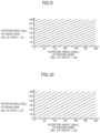
- FIG. 9 is a graph showing a correlation between the rotation angle of the second driven gear and the rotation angle of the third driven gear
- FIG. 10 is a graph showing a correlation between the rotation angle of the third driven gear and the rotation angle of the first driven gear
- FIG. 11 is a graph showing different absolute angle detection ranges corresponding to combinations of angle signals
- FIG. 12 is a block diagram illustrating power supply paths and detection signal output paths of a first rotation angle detection device
- FIG. 13 is a block diagram illustrating power supply paths and detection signal output paths of a second rotation angle detection device
- FIG. 14 is a drawing showing combinations of angle signals usable for calculating absolute angles in a case in which all sensor power supply circuits are operating normally;
- FIG. 15 is a drawing showing combinations of angle signals usable for calculating absolute angles in a case in which an angle signal ⁇ 30 a and an angle signal ⁇ 33 a indicate abnormal values due to a failure of a sensor power supply circuit;
- FIG. 16 is a drawing showing combinations of angle signals usable for calculating absolute angles in a case in which an angle signal ⁇ 27 b and an angle signal ⁇ 30 b indicate abnormal values due to a failure of a sensor power supply circuit;
- FIG. 17 is a drawing showing combinations of angle signals usable for calculating absolute angles in a case in which an angle signal ⁇ 27 a and an angle signal ⁇ 33 b indicate abnormal values due to a failure of a sensor power supply circuit;
- FIG. 18 is a flowchart illustrating a failure diagnosis process for MR sensor elements based on detection results of the MR sensor elements
- FIG. 19 is a flowchart illustrating the failure diagnosis process for the MR sensor elements based on the detection results of the MR sensor elements
- FIG. 20 is a flowchart illustrating the failure diagnosis process for the MR sensor elements based on the detection results of the MR sensor elements
- FIG. 21 is a flowchart illustrating the failure diagnosis process for the MR sensor elements based on the detection results of the MR sensor elements
- FIG. 22 is a flowchart illustrating a failure diagnosis process for MR sensor elements based on detection results of the MR sensor elements and a detection result of a motor rotation sensor;
- FIG. 23 is a flowchart illustrating the failure diagnosis process for the MR sensor elements based on the detection results of the MR sensor elements and the detection result of the motor rotation sensor;
- FIG. 24 is a flowchart illustrating the failure diagnosis process for the MR sensor elements based on the detection results of the MR sensor elements and the detection result of the motor rotation sensor;
- FIG. 25 is a flowchart illustrating the failure diagnosis process for the MR sensor elements based on the detection results of the MR sensor elements and the detection result of the motor rotation sensor;
- FIG. 26 is a flowchart illustrating a process of calculating an offset amount ⁇ osmot of a motor rotation angle
- FIG. 27 is a flowchart illustrating a process of calculating a motor rotation count TC.
- a rotation angle detection device according to an embodiment of the present invention is described below with reference to the drawings.
- FIG. 1 is a drawing illustrating an embodiment of a steer-by-wire steering system 1000 provided in a vehicle 1 such as an automobile.
- Steer-by-wire steering system 1000 controls the steering angle, in other words, the steering amount, of steered road wheels 2 L and 2 R that are front tires of vehicle 1 .
- Steered road wheels 2 L and 2 R are mechanically separated from a steering wheel 500 .
- Steer-by-wire steering system 1000 includes a steering device 2000 and a steering input device 3000 .
- Steering device 2000 includes an electric motor 100 that functions as a steering actuator for generating steering force applied to steered road wheels 2 L and 2 R, a first electronic control unit (ECU) 200 that drives and controls electric motor 100 , a steering mechanism 300 , and a first rotation angle detection device 400 (in other words, a rotation angle detector) that detects the position (for example, a rack position) of steering mechanism 300 as an amount related to the steering amount of steered road wheels 2 L and 2 R.
- ECU electronice control unit
- first rotation angle detection device 400 in other words, a rotation angle detector
- Steering mechanism 300 converts the rotational motion of the output shaft of electric motor 100 into a linear motion of a steering rod 310 .
- steering mechanism 300 is implemented by a rack and pinion mechanism.
- the rotational driving force of electric motor 100 is transmitted to a pinion shaft 330 via a reducer 320 .
- steering rod 310 includes a rack 311 that meshes with a pinion 331 provided on pinion shaft 330 .
- pinion 331 rotates, steering rod 310 moves horizontally in a lateral direction with respect to the traveling direction of vehicle 1 , and as a result, the steering angle of steered road wheels 2 L and 2 R changes.
- Electric motor 100 is a brushless motor and includes a motor rotation angle sensor 101 that detects a rotor position.
- steering mechanism 300 may be implemented by, for example, a mechanism using a ball screw instead of a rack and pinion mechanism.
- Steering input device 3000 includes steering wheel 500 operated by a driver of vehicle 1 , a steering shaft 510 that rotates along with the rotation of steering wheel 500 , an electric motor 600 used as a steering reaction force actuator that generates steering reaction force, a second ECU 700 that drives and controls electric motor 600 , and a second rotation angle detection device 800 (in other words, a rotation angle detector) that detects a steering angle of steering wheel 500 .
- First ECU 200 of steering device 2000 obtains information on a steering angle of steering wheel 500 detected by second rotation angle detection device 800 , and compares the information on the steering angle with information on a steering amount of steered road wheels 2 L and 2 R detected by first rotation angle detection device 400 to control electrification of electric motor 100 .
- second ECU 700 of steering input device 3000 controls electrification of electric motor 600 based on information on target reaction force torque generated based on, for example, an estimation result of external force applied to steering mechanism 300 , and thereby generates steering reaction force.
- Electric motor 600 is a brushless motor and includes a motor rotation angle sensor 601 that detects a rotor position.
- the position (in other words, the steering amount) of steering mechanism 300 detected by first rotation angle detection device 400 and the steering angle of steering wheel 500 detected by second rotation angle detection device 800 are steering state quantities of steer-by-wire steering system 1000 .
- Two control devices implemented by first ECU 200 and second ECU 700 constitute a control device 1100 that outputs signals used to control steer-by-wire in steer-by-wire steering system 1000 .
- FIG. 2 is a block diagram illustrating a configuration of first ECU 200 of steering device 2000 .
- Electric motor 100 for generating steering force in steering device 2000 is, for example, a three-phase brushless motor and includes a first coil set 100 a and a second coil set 100 b each of which includes a U-phase coil, a V-phase coil, and a W-phase coil.
- First ECU 200 includes two drive control systems 210 a and 210 b that separately drive and control coil sets 100 a and 100 b .
- first ECU 200 includes redundant drive control systems for electric motor 100 .
- First drive control system 210 a that drives and controls first coil set 100 a includes a first power supply circuit 211 a , a first inverter 212 a , a first pre-driver 213 a , a first micro control unit (MCU) 214 a that is an arithmetic processing unit, and a first CAN (Controller Area Network) transceiver 215 a.
- MCU micro control unit
- Second drive control system 210 b that drives and controls second coil set 100 b includes a second power supply circuit 211 b , a second inverter 212 b , a second pre-driver 213 b , a second MCU 214 b that is an arithmetic processing unit, and a second CAN transceiver 215 b.
- First power supply circuit 211 a is connected to a first battery 51 a provided in vehicle 1 , converts an input power supply voltage from first battery 51 a into an internal power supply voltage, and supplies the internal power supply voltage to, for example, a first pre-driver 213 a , a first MCU 214 a , and a first CAN transceiver 215 a in first drive control system 210 a.
- Second power supply circuit 211 b is connected to a second battery 51 b provided in vehicle 1 , converts an input power supply voltage from second battery 51 b into an internal power supply voltage, and supplies the internal power supply voltage to, for example, a second pre-driver 213 b , a second MCU 214 b , and a second CAN transceiver 215 b in second drive control system 210 b.
- first drive control system 210 a and second drive control system 210 b receive power from different power supplies (batteries).
- each of the input power supply voltages from first battery 51 a and second battery 51 b is, for example, 12 V; and each of the internal power supply voltages generated by first power supply circuit 211 a and second power supply circuit 211 b is, for example, 5 V.
- First MCU 214 a and second MCU 214 b send information to, and receive information from, each other via a communication line 220 .
- each of first MCU 214 a and second MCU 214 b sends various types of failure information or information about inverter control in the corresponding control system to the other.
- first CAN transceiver 215 a and second CAN transceiver 215 b are connected to a vehicle CAN bus 52 that is a communication line in a controller area network (CAN) communication method.
- vehicle CAN bus 52 that is a communication line in a controller area network (CAN) communication method.
- Each of first MCU 214 a and second MCU 214 b obtains a signal related to a steering amount output by first rotation angle detection device 400 , also obtains information about a steering angle of steering wheel 500 from second ECU 700 via vehicle CAN bus 52 , and controls electrification of coil sets 100 a and 100 b based on the obtained signal and information.
- first MCU 214 a and second MCU 214 b control the steering amount of steered road wheels 2 L and 2 R to match a target value corresponding to the steering angle of steering wheel 500 by controlling the electrification of coil sets 100 a and 100 b.
- FIG. 3 is a block diagram illustrating a configuration of second ECU 700 of steering input device 3000 .
- steering input device 3000 also includes redundant drive control systems for electric motor 600 .
- Electric motor 600 that generates steering reaction force in steering input device 3000 is, for example, a three-phase brushless motor and includes a first coil set 600 a and a second coil set 600 b each of which includes a U-phase coil, a V-phase coil, and a W-phase coil.
- Second ECU 700 includes two drive control systems 710 a and 710 b that separately drive and control coil sets 600 a and 600 b .
- second ECU 700 includes redundant drive control systems for electric motor 600 .
- First drive control system 710 a that drives and controls first coil set 600 a includes a first power supply circuit 711 a , a first inverter 712 a , a first pre-driver 713 a , a first MCU 714 a , and a first CAN transceiver 715 a.
- Second drive control system 710 b that drives and controls second coil set 600 b includes a second power supply circuit 711 b , a second inverter 712 b , a second pre-driver 713 b , a second MCU 714 b , and a second CAN transceiver 715 b.
- First power supply circuit 711 a is connected to first battery 51 a provided in vehicle 1 , converts an input power supply voltage from first battery 51 a into an internal power supply voltage, and supplies the internal power supply voltage to, for example, first pre-driver 713 a , first MCU 714 a , and first CAN transceiver 715 a in first drive control system 710 a.
- Second power supply circuit 711 b is connected to second battery 51 b provided in vehicle 1 , converts an input power supply voltage from second battery 51 b into an internal power supply voltage, and supplies the internal power supply voltage to second pre-driver 713 b , second MCU 714 b , and second CAN transceiver 715 b in second drive control system 710 b.
- first battery 51 a supplies power to first drive control system 210 a of first ECU 200 and first drive control system 710 a of second ECU 700 ; and second battery 51 b supplies power to second drive control system 210 b of first ECU 200 and second drive control system 710 b of second ECU 700 .
- First MCU 714 a and second MCU 714 b send and receive information to and from each other via a communication line 720 .
- each of first MCU 714 a and second MCU 714 b sends various types of failure information or information about inverter control in the corresponding control system to the other.
- first CAN transceiver 715 a and second CAN transceiver 715 b are connected to vehicle CAN bus 52 .
- Each of first MCU 714 a and second MCU 714 b obtains a signal related to the steering angle of steering wheel 500 output by second rotation angle detection device 800 , and sends information on the steering angle to first ECU 200 of steering device 2000 via vehicle CAN bus 52 .
- each of first MCU 714 a and second MCU 714 b obtains information on a target value of steering reaction force from steering device 2000 via vehicle CAN bus 52 , and controls steering reaction force generated by electric motor 600 by controlling electrification of coil sets 600 a and 600 b based on the obtained information.
- first rotation angle detection device 400 and second rotation angle detection device 800 are described.
- first rotation angle detection device 400 and second rotation angle detection device 800 have the same configuration as rotation angle detectors, separate descriptions of these devices are omitted.
- FIG. 4 is a drawing illustrating a configuration of each of first rotation angle detection device 400 and second rotation angle detection device 800 .
- Each of first rotation angle detection device 400 and second rotation angle detection device 800 is attached to a rotating shaft part 910 that is rotated by an amount of rotation corresponding to the steering state quantity of steer-by-wire, and rotating shaft part 910 rotates about a rotation axis AR.
- rotating shaft part 910 in first rotation angle detection device 400 corresponds to, for example, pinion shaft 330 in steering mechanism 300
- rotating shaft part 910 in second rotation angle detection device 800 corresponds to, for example, steering shaft 510
- rotating shaft part 910 may be implemented by a rotating shaft part that is different from pinion shaft 330 or steering shaft 510 and that rotates along with the rotation of pinion shaft 330 or steering shaft 510 .
- a drive gear 920 (gear wheel), which rotates along with the rotation of rotating shaft part 910 , is provided on the outer circumference of rotating shaft part 910 .
- each of three driven gears 931 , 932 , and 933 meshes with drive gear 920 and rotates in conjunction with the rotation of drive gear 920 .
- Three driven gears 931 , 932 , and 933 have different numbers of teeth.
- the number of teeth of drive gear 920 is set at 60
- the number of teeth of first driven gear 931 is set at 27
- the number of teeth of second driven gear 932 is set at 30, and the number of teeth of third driven gear 933 is set at 33.
- the ratio of the numbers of teeth of three driven gears 931 , 932 , and 933 is 9:10:11, and the numbers of teeth 27 , 30 , and 33 of three driven gears 931 , 932 , and 933 are natural number multiples (triples) of the ratio 9:10:11.
- the numbers of teeth of three driven gears 931 , 932 , and 933 are triples (27, 30, and 33) of the ratio 9:10:11.
- the numbers of teeth of three driven gears 931 , 932 , and 933 may be set at twice the ratio 9:10:11. That is, the number of teeth of first driven gear 931 may be set at 18, the number of teeth of second driven gear 932 may be set at 20, and the number of teeth of third driven gear 933 may be set at 22.
- the numbers of teeth of three driven gears 931 , 932 , and 933 are different from each other and indivisible by each other. Also, the numbers of teeth of three driven gears 931 , 932 , and 933 are set such that when they are divided by the greatest common factor, the quotients represent a ratio (9:10:11) of natural numbers including two different odd numbers and one even number.
- the number of teeth of drive gear 920 is set at a value that is greater than or equal to twice the number of teeth of one of three driven gears 931 , 932 , and 933 having the smallest number of teeth.
- the number of teeth of first driven gear 931 is 27, the number of teeth of second driven gear 932 is 30, and the number of teeth of third driven gear 933 is 33, the smallest number of teeth is 27, and the number of teeth of drive gear 920 is set at a value greater than or equal to 54 that is two times greater than 27.
- the numbers of teeth of drive gear 920 and driven gears 931 , 932 , and 933 are adjusted such that the range of the absolute angle of drive gear 920 , which is obtained based on the combination of detection signals of the rotation angles of driven gears 931 , 932 , and 933 , includes the detection range of the steering state quantity of steer-by-wire.
- the numbers of teeth are set such that the absolute angle can be detected within the range of the number of lock-to-lock rotations (for example, 4-5 rotations) of steering wheel 500 .
- each of three driven gears 931 , 932 , and 933 meshes with drive gear 920 .
- driven gears 931 , 932 , and 933 may be meshed with each other.
- first driven gear 931 and third driven gear 933 may be meshed with drive gear 920
- second driven gear 932 may be meshed with first driven gear 931 or third driven gear 933 .
- first driven gear 931 may be meshed with drive gear 920
- second driven gear 932 may be meshed with first driven gear 931
- third driven gear 933 may be meshed with second driven gear 932 .
- first driven gear 931 may be meshed with drive gear 920
- second driven gear 932 and third driven gear 933 may be meshed with first driven gear 931 .
- magnetic angle sensors for detecting the amounts of rotation (specifically, absolute angles) of respective driven gears 931 , 932 , and 933 are described.
- Dipole magnets 941 , 942 , and 943 are attached to the axial centers of respective driven gears 931 , 932 , and 933 , and angle sensors 951 , 952 , and 953 are disposed to face corresponding magnets 941 , 942 , and 943 .
- Each of magnets 941 , 942 , and 943 is divided into an N pole and an S pole along a straight line passing through the center of the rotation axis of the corresponding one of driven gears 931 , 932 , and 933 in a cross section orthogonal to the rotation axis.
- Angle sensors 951 , 952 , and 953 are disposed to face the corresponding magnets 941 , 942 , and 943 in the axial directions of driven gears 931 , 932 , and 933 .
- Each of angle sensors 951 , 952 , and 953 includes a magnetoresistive sensor element (MR sensor element) that converts a change in the magnetic field caused by the rotation of the corresponding one of magnets 941 , 942 , and 943 into an electrical resistance, also converts the electrical resistance into a voltage, and outputs the voltage as an analog signal.
- MR sensor element magnetoresistive sensor element
- First angle sensor 951 detects the amount of rotation of first driven gear 931
- second angle sensor 952 detects the amount of rotation of second driven gear 932
- third angle sensor 953 detects the amount of rotation of third driven gear 933 .
- each of angle sensors 951 , 952 , and 953 is a dual die including two MR sensor elements.
- First angle sensor 951 integrally includes a first MR sensor element 27 a and a second MR sensor element 27 b
- second angle sensor 952 integrally includes a first MR sensor element 30 a and a second MR sensor element 30 b
- third angle sensor 953 integrally includes a first MR sensor element 33 a and a second MR sensor element 33 b.
- each of angle sensors 951 , 952 , and 953 has a redundant configuration.
- first driven gear 931 The amount of rotation of first driven gear 931 is detected by first MR sensor element 27 a (first sensor) and second MR sensor element 27 b (second sensor).
- first MR sensor element 30 a third sensor
- second MR sensor element 30 b fourth sensor
- first MR sensor element 33 a farth sensor
- second MR sensor element 33 b ixth sensor
- each of MR sensor elements 27 a , 27 b , 30 a , 30 b , 33 a , and 33 b is implemented by a combination of four sensor elements having different magnetic sensing directions.
- MR sensor elements 27 a , 27 b , 30 a , 30 b , 33 a , and 33 b output, as rotation amount signals, angle signals ⁇ 27 a , ⁇ 27 b , ⁇ 30 a , ⁇ 30 b , ⁇ 33 a , and ⁇ 33 b , respectively, each of angle signals ⁇ 27 a , ⁇ 27 b , ⁇ 30 a , ⁇ 30 b , ⁇ 33 a , and ⁇ 33 b indicating an absolute angle (0 deg.-360 deg.) of the corresponding one of driven gears 931 , 932 , and 933 .
- Each of MCUs 214 a , 214 b , 714 a , and 714 b of first ECU 200 and second ECU 700 functions, as described later, as a rotation amount generating unit that obtains the amount of rotation (absolute angle) of rotating shaft part 910 (drive gear 920 ) by combining two angle signals of different driven gears among angle signals ⁇ 27 a , ⁇ 27 b , ⁇ 30 a , ⁇ 30 b , ⁇ 33 a , and ⁇ 33 b.
- the rotation amount generating unit obtains the amount of rotation of rotating shaft part 910 based on detection values of a combination of sensors that is different from the combination of first MR sensor element 27 a and second MR sensor element 27 b , the combination of first MR sensor element 30 a and second MR sensor element 30 b , and the combination of first MR sensor element 33 a and second MR sensor element 33 b.
- each of MCUs 214 a , 214 b , 714 a , and 714 b of first ECU 200 and second ECU 700 outputs a signal such as a motor drive signal used to control steer-by-wire based on the obtained amount of rotation of rotating shaft part 910 , i.e., the amount of rotation (the steering amount of steered road wheels 2 L and 2 R or the steering angle of steering wheel 500 ) corresponding to the steering state quantity of steer-by-wire.
- a signal such as a motor drive signal used to control steer-by-wire based on the obtained amount of rotation of rotating shaft part 910 , i.e., the amount of rotation (the steering amount of steered road wheels 2 L and 2 R or the steering angle of steering wheel 500 ) corresponding to the steering state quantity of steer-by-wire.
- control device 1100 determines the target value of the steering amount based on a detection result of the steering angle of steering wheel 500 , and controls electric motor 100 used as a steering actuator such that the detection value of the steering amount of steered road wheels 2 L and 2 R becomes closer to the target value.
- FIG. 5 shows changes in angle signal ⁇ 27 a of first MR sensor element 27 a and angle signal ⁇ 27 b of second MR sensor element 27 b in first angle sensor 951 for detecting the rotation angle of first driven gear 931 .
- FIG. 6 shows changes in angle signal ⁇ 30 a of first MR sensor element 30 a and angle signal ⁇ 30 b of second MR sensor element 30 b in second angle sensor 952 for detecting the rotation angle of second driven gear 932 .
- FIG. 7 shows changes in angle signal ⁇ 33 a of first MR sensor element 33 a and angle signal ⁇ 33 b of second MR sensor element 33 b in third angle sensor 953 for detecting the rotation angle of third driven gear 933 .
- An angle signal output by each of MR sensor elements constituting each of angle sensors 951 , 952 , and 953 has a cycle that corresponds to one rotation of corresponding driven gear 931 , 932 , or 933 ; and angle signals of two sensors for detecting the rotation angle of each of driven gears 931 , 932 , and 933 are output such that the phases of the angle signals are shifted from each other by a half cycle.
- FIGS. 8 - 10 are graphs showing correlations between rotation angles of driven gears 931 , 932 , and 933 .
- FIG. 8 shows a correlation between the rotation angle [deg.] of first driven gear 931 and the rotation angle [deg.] of second driven gear 932
- FIG. 9 shows a correlation between the rotation angle [deg.] of second driven gear 932 and the rotation angle [deg.] of third driven gear 933
- FIG. 10 shows a correlation between the rotation angle [deg.] of first driven gear 931 and the rotation angle [deg.] of third driven gear 933 .
- FIG. 11 shows absolute angles of rotating shaft part 910 that are calculated based on three exemplary combinations of angle signals output by angle sensors 951 , 952 , and 953 .
- a first absolute angle detection value ⁇ A 1 is the absolute angle of rotating shaft part 910 that is obtained based on a combination of an angle signal ⁇ 30 a of first MR sensor element 30 a for detecting the rotation angle of second driven gear 932 and an angle signal ⁇ 33 a of first MR sensor element 33 a for detecting the rotation angle of third driven gear 933 .
- a second absolute angle detection value ⁇ A 2 is the absolute angle of rotating shaft part 910 that is obtained based on a combination of an angle signal ⁇ 33 b of second MR sensor element 33 b for detecting the rotation angle of third driven gear 933 and an angle signal ⁇ 27 a of first MR sensor element 27 a for detecting the rotation angle of first driven gear 931 .
- a third absolute angle detection value ⁇ A 3 is the absolute angle of rotating shaft part 910 that is obtained based on a combination of an angle signal ⁇ 27 b of second MR sensor element 27 b for detecting the rotation angle of first driven gear 931 and an angle signal ⁇ 30 b of second MR sensor element 30 b for detecting the rotation angle of second driven gear 932 .
- the range of the absolute angle of rotating shaft part 910 detectable based on a combination of angle signals varies depending on cycles that differ depending on the numbers of teeth of driven gears.
- drive gear 920 rotates 33/60 times, i.e., 198 degrees, while third driven gear 933 with 33 teeth rotates once.
- drive gear 920 rotates 30/60 times, i.e., 180 degrees, while second driven gear 932 with 30 teeth rotates once.
- phases of angle signal ⁇ 30 a of first MR sensor element 30 a for detecting the rotation angle of second driven gear 932 and angle signal ⁇ 33 a of first MR sensor element 33 a for detecting the rotation angle of third driven gear 933 again become the same as those when the absolute angle of drive gear 920 is 0 degrees.
- absolute angle ⁇ A 1 of drive gear 920 obtained based on the combination of angle signal ⁇ 30 a of first MR sensor element 30 a for detecting the rotation angle of second driven gear 932 and angle signal ⁇ 33 a of first MR sensor element 33 a for detecting the rotation angle of third driven gear 933 falls in a range between 0 degrees and 1980 degrees.
- Absolute angle ⁇ A 2 falls in a range between 0 degrees and 1782 degrees
- absolute angle ⁇ A 3 falls in a range between 0 degrees and 1620 degrees.
- the range of the absolute angle of drive gear 920 obtainable based on a combination of angle signals of driven gears 931 , 932 , and 933 depends on the difference between the cycles of rotation angle signals to be combined, in other words, it depends on the difference in the number of teeth between driven gears 931 , 932 , and 933 .
- the numbers of teeth of driven gears 931 , 932 , and 933 and combinations of angle signals used to detect the absolute angle are set so as to enable detection of the absolute angle of rotating shaft part 910 in a detection range required for the steer-by-wire steering system 1000 , in other words, to enable detection of a required number of rotations of rotating shaft part 910 .
- FIG. 12 is a block diagram illustrating power supply paths to respective MR sensor elements and output paths of detection signals of respective MR sensor elements in first rotation angle detection device 400 according to an embodiment.
- a first sensor power supply circuit 217 a to which power is supplied from first battery 51 a is provided in first drive control system 210 a of first ECU 200
- a second sensor power supply circuit 217 b to which power is supplied from second battery 51 b is provided in second drive control system 210 b of first ECU 200 .
- a fourth sensor power supply circuit 717 b to which power is supplied from second battery 51 b is provided in second drive control system 710 b of second ECU 700 .
- first power supply line 217 a 1 (first power supply) for supplying power from first sensor power supply circuit 217 a to first MR sensor element 30 a
- second power supply line 217 a 2 (second power supply) for supplying power from first sensor power supply circuit 217 a to first MR sensor element 33 a.
- a third power supply line 217 b 3 (third power supply) for supplying power from second sensor power supply circuit 217 b to second MR sensor element 27 b
- a fourth power supply line 217 b 4 (fourth power supply) for supplying power from second sensor power supply circuit 217 b to second MR sensor element 30 b.
- a fifth power supply line 717 b 5 for supplying power from fourth sensor power supply circuit 717 b to second MR sensor element 33 b
- a sixth power supply line 717 b 6 for supplying power from fourth sensor power supply circuit 717 b to first MR sensor element 27 a.
- control device 1100 includes three sensor power supply circuits including first sensor power supply circuit 217 a (first power supply circuit), second sensor power supply circuit 217 b (second power supply circuit), and fourth sensor power supply circuit 717 b (third power supply circuit).
- MR sensor elements 27 a , 27 b , 30 a , 30 b , 33 a , and 33 b are grouped into three combination patterns, each of which is a combination of MR sensor elements for detecting the amounts of rotation of driven gears that are different from each other; and one of three sensor power supply circuits 217 a , 217 b , and 717 b is assigned to each of the combination patterns.
- each of three sensor power supply circuits 217 a , 217 b , and 717 b supplies power to two MR sensor elements, and each of MR sensor elements 27 a , 27 b , 30 a , 30 b , 33 a , and 33 b is supplied with power from one of three MR sensor elements 217 a , 217 b , and 717 b.
- three sensor power supply circuits 217 a , 217 b , and 717 b for supplying power to respective MR sensor elements 27 a , 27 b , 30 a , 30 b , 33 a , and 33 b of first rotation angle detection device 400 are provided in separate drive control systems 210 a , 210 b , and 710 b ;
- first ECU 200 includes two sensor power supply circuits 217 a and 217 b ; and second ECU 700 includes one sensor power supply circuit 717 b.
- providing triple-redundant sensor power supply circuits improves the robustness against failure of sensor power supply circuits. Also, providing three sensor power supply circuits 217 a , 217 b , and 717 b in separate control devices (in other words, multiple drive control systems) improves the robustness against failure of sensor power supply circuits.
- first sensor power supply circuit 217 a is supplied with power from first battery 51 a
- second sensor power supply circuit 217 b and fourth sensor power supply circuit 717 b are supplied with power from second battery 51 b
- at least one of the sensor power supply circuits can continue to supply power even if one of first battery 51 a and second battery 51 b fails.
- each drive control system includes a power supply circuit for supplying power to, for example, an MCU and a sensor power supply circuit that are supplied with power from the same battery; and as described later, each drive control system obtains outputs of MR sensor elements that are supplied with power from the sensor power supply circuit of the drive control system.
- first MCU 214 a can obtain angle signal ⁇ 30 a and angle signal ⁇ 33 a to calculate the absolute angle (steering amount) of rotating shaft part 910 and can perform electrification control (in other words, steering control) of first coil set 100 a of electric motor 100 .
- first drive control system 710 a of second ECU 700 also receives power from first battery 51 a , first drive control system 710 a can detect the absolute angle of steering shaft 510 and send information on the detected absolute angle to first ECU 200 , and can also continue control of steering reaction force.
- first ECU 200 when first ECU 200 has triple-redundant drive control systems, a sensor power supply circuit may be provided in each of the drive control systems so that first ECU 200 includes three sensor power supply circuits.
- a system may be configured such that power is supplied to MR sensor elements of first rotation angle detection device 400 from the sensor power supply circuit (first power supply circuit) provided in first drive control system 710 a of second ECU 700 , the sensor power supply circuit (second power supply circuit) provided in second drive control system 710 b of second ECU 700 , and the sensor power supply circuit (third power supply circuit) provided in second drive control system 210 b of first ECU 200 .
- Each of first MCU 214 a and second MCU 214 b of first ECU 200 is connected to first MR sensor element 30 a , first MR sensor element 33 a , second MR sensor element 27 b , and second MR sensor element 30 b constituting first rotation angle detection device 400 , and obtains angle signal ⁇ 30 a from first MR sensor element 30 a , angle signal ⁇ 33 a from first MR sensor element 33 a , angle signal ⁇ 27 b from second MR sensor element 27 b , and angle signal ⁇ 30 b from second MR sensor element 30 b.
- second MCU 714 b of second ECU 700 is connected to second MR sensor element 33 b and first MR sensor element 27 a constituting first rotation angle detection device 400 , and obtains angle signal ⁇ 33 b from second MR sensor element 33 b and angle signal ⁇ 27 a from first MR sensor element 27 a.
- Each of first MCU 214 a , second MCU 214 b , and second MCU 714 b includes a function of a rotation amount generating unit that detects the absolute angle of rotating shaft part 910 (pinion shaft 330 ) on which drive gear 920 is provided, i.e., an amount (amount of rotation) related to the steering amount of steered road wheels 2 L and 2 R, by combining detection results that are among the obtained angle signals and are related to different driven gears.
- information on the angle signals obtained by first MCU 214 a , second MCU 214 b , and second MCU 714 b from first rotation angle detection device 400 and the absolute angles of rotating shaft part 910 (pinion shaft 330 ) obtained by first MCU 214 a , second MCU 214 b , and second MCU 714 b can be shared by MCUs 214 a , 214 b , 714 a , and 714 b by communication via vehicle CAN bus 52 and communication lines 220 and 720 between MCUs.
- first MCU 714 a instead of second MCU 714 b , supplies power to second MR sensor element 33 b and first MR sensor element 27 a , and obtains angle signals from second MR sensor element 33 b and first MR sensor element 27 a.
- first ECU 200 and second ECU 700 including functions of controlling steer-by-wire, i.e., control device 1100 , obtain angle signals output by MR sensor elements 27 a , 27 b , 30 a , 30 b , 33 a , and 33 b of first rotation angle detection device 400 , and perform calculation processes to obtain the absolute angle (the amount of rotation) of rotating shaft part 910 (pinion shaft 330 ).
- first rotation angle detection device 400 includes an arithmetic processing unit such as an MCU or an MPU, and the arithmetic processing unit of first rotation angle detection device 400 performs a calculation process to combine angle signals and thereby obtain the absolute angle (the amount of rotation) of rotating shaft part 910 (pinion shaft 330 ).
- FIG. 13 is a block diagram illustrating power supply paths to MR sensor elements and output signal lines of the MR sensor elements in second rotation angle detection device 800 according to an embodiment.
- first ECU 200 and second ECU 700 in FIG. 12 are interchanged, the power supply paths and the output signal lines have configurations similar to those in FIG. 12 .
- First drive control system 710 a of second ECU 700 includes a third sensor power supply circuit 717 a (first power supply circuit) connected to first battery 51 a.
- first power supply line 717 a 1 (first power supply) for supplying power from third sensor power supply circuit 717 a to first MR sensor element 30 a
- second power supply line 717 a 2 (second power supply) for supplying power from third sensor power supply circuit 717 a to first MR sensor element 33 a.
- a third power supply line 717 b 3 (third power supply) for supplying power from fourth sensor power supply circuit 717 b (second power supply circuit) of second ECU 700 to second MR sensor element 27 b
- a fourth power supply line 717 b 4 (fourth power supply) for supplying power from fourth sensor power supply circuit 717 b to second MR sensor element 30 b.
- a fifth power supply line 217 b 5 for supplying power from second sensor power supply circuit 217 b (third power supply circuit) of first ECU 200 to second MR sensor element 33 b
- a sixth power supply line 217 b 6 for supplying power from second sensor power supply circuit 217 b to first MR sensor element 27 a.
- Each of first MCU 714 a and second MCU 714 b of second ECU 700 is connected to first MR sensor element 30 a , first MR sensor element 33 a , second MR sensor element 27 b , and second MR sensor element 30 b constituting second rotation angle detection device 800 , and obtains angle signal ⁇ 30 a from first MR sensor element 30 a , angle signal ⁇ 33 a from first MR sensor element 33 a , angle signal ⁇ 27 b from second MR sensor element 27 b , and angle signal ⁇ 30 b from second MR sensor element 30 b.
- second MCU 214 b of first ECU 200 is connected to second MR sensor element 33 b and first MR sensor element 27 a constituting second rotation angle detection device 800 , and obtains angle signal ⁇ 33 b from second MR sensor element 33 b and angle signal ⁇ 27 a from first MR sensor element 27 a.
- Each of first MCU 714 a , second MCU 714 b , and second MCU 214 b includes a function (rotation angle generation unit) that detects the absolute angle of rotating shaft part 910 (steering shaft 510 ) on which drive gear 920 is provided, i.e., the amount of rotation of steering wheel 500 , by combining detection results that are among the obtained angle signals and are related to different driven gears.
- a function rotation angle generation unit
- second rotation angle detection device 800 similarly to first rotation angle detection device 400 , information on the angle signals output by MR sensor elements and the absolute angle of rotating shaft part 910 (steering shaft 510 ) can be shared by MCUs 214 a , 214 b , 714 a , and 714 b through communication via vehicle CAN bus 52 and communication lines 220 and 720 between MCUs.
- first MCU 214 a instead of second MCU 214 b , supplies power to second MR sensor element 33 b and first MR sensor element 27 a , and obtains angle signals from second MR sensor element 33 b and first MR sensor element 27 a.
- second rotation angle detection device 800 includes an arithmetic processing unit such as an MCU or an MPU, and the arithmetic processing unit of second rotation angle detection device 800 performs a calculation process to combine angle signals and thereby obtain the absolute angle (the amount of rotation) of rotating shaft part 910 (steering shaft 510 ).
- FIG. 14 through FIG. 17 show combinations of angle signals that are usable for calculating the absolute angle of rotating shaft part 910 and that vary depending on whether there is a failed sensor power supply.
- FIG. 14 shows combinations of angle signals that are usable for calculating the absolute angle of rotating shaft part 910 when all of three sensor power supply circuits illustrated in FIG. 12 or FIG. 13 , i.e., three sensor power supply circuits 217 a , 217 b , and 717 b for supplying power to MR sensor elements constituting first rotation angle detection device 400 or three sensor power supply circuits 717 a , 717 b , and 217 b for supplying power to MR sensor elements constituting second rotation angle detection device 800 , are operating normally.
- the absolute angle of rotating shaft part 910 can be calculated based on a combination of angle signal ⁇ 27 a and one of angle signal ⁇ 30 a , angle signal ⁇ 30 b , angle signal ⁇ 33 a , and angle signal ⁇ 33 b , a combination of angle signal ⁇ 27 b and one of angle signal ⁇ 30 a , angle signal ⁇ 30 b , angle signal ⁇ 33 a , and angle signal ⁇ 33 b , a combination of angle signal ⁇ 30 a and one of angle signal ⁇ 33 a and angle signal ⁇ 33 b , or a combination of angle signal ⁇ 30 b and one of angle signal ⁇ 33 a and angle signal ⁇ 33 b.
- FIG. 15 shows combinations of angle signals that are usable for calculating the absolute angle of rotating shaft part 910 when a sensor power supply circuit for supplying power to first MR sensor element 30 a and first MR sensor element 33 a , i.e., first sensor power supply circuit 217 a in FIG. 12 or third sensor power supply circuit 717 a in FIG. 13 , fails, power is therefore not normally supplied to first MR sensor element 30 a and first MR sensor element 33 a , and first MR sensor element 30 a and first MR sensor element 33 a do not operate normally.
- a sensor power supply circuit for supplying power to first MR sensor element 30 a and first MR sensor element 33 a i.e., first sensor power supply circuit 217 a in FIG. 12 or third sensor power supply circuit 717 a in FIG. 13 .
- angle signal ⁇ 30 a and angle signal ⁇ 33 a become unusable for calculating the absolute angle of rotating shaft part 910 .
- the absolute angle of rotating shaft part 910 can be calculated by using any one of combinations excluding combinations using angle signal ⁇ 30 a and/or angle signal ⁇ 33 a.
- the absolute angle of rotating shaft part 910 can be calculated using a combination of angle signal ⁇ 27 a and one of angle signal ⁇ 30 b and angle signal ⁇ 33 b , a combination of angle signal ⁇ 27 b and one of angle signal ⁇ 30 b and angle signal ⁇ 33 b , or a combination of angle signal ⁇ 30 b and angle signal ⁇ 33 b.
- the absolute angle of rotating shaft part 910 can be calculated using any one of five combinations.
- FIG. 16 shows combinations of angle signals that are usable for calculating the absolute angle of rotating shaft part 910 when a sensor power supply circuit (second sensor power supply circuit 217 b in FIG. 12 or fourth sensor power supply circuit 717 b in FIG. 13 ) for supplying power to second MR sensor element 27 b and second MR sensor element 30 b fails.
- a sensor power supply circuit second sensor power supply circuit 217 b in FIG. 12 or fourth sensor power supply circuit 717 b in FIG. 13
- angle signal ⁇ 27 b and angle signal ⁇ 30 b become unusable for calculating the absolute angle of rotating shaft part 910 .
- the absolute angle of rotating shaft part 910 can be calculated by using any one of combinations excluding combinations using angle signal ⁇ 27 b and/or angle signal ⁇ 30 b.
- the absolute angle of rotating shaft part 910 can be calculated using a combination of angle signal ⁇ 27 a and one of angle signal ⁇ 30 a , angle signal ⁇ 33 a , and angle signal ⁇ 33 b or a combination of angle signal ⁇ 30 a and one of angle signal ⁇ 33 a and angle signal ⁇ 33 b.
- the absolute angle of rotating shaft part 910 can be calculated using any one of five combinations.
- FIG. 17 shows combinations of angle signals that are usable for calculating the absolute angle of rotating shaft part 910 when a sensor power supply circuit (fourth sensor power supply circuit 717 b in FIG. 12 or second sensor power supply circuit 217 b in FIG. 13 ) for supplying power to first MR sensor element 33 a and second MR sensor element 27 b fails.
- a sensor power supply circuit fourth sensor power supply circuit 717 b in FIG. 12 or second sensor power supply circuit 217 b in FIG. 13
- angle signal ⁇ 27 a and angle signal ⁇ 33 b become unusable for calculating the absolute angle of rotating shaft part 910 .
- the absolute angle ⁇ of rotating shaft part 910 can be calculated by using any one of combinations excluding combinations using angle signal ⁇ 27 a and/or angle signal ⁇ 33 b.
- the absolute angle of rotating shaft part 910 can be calculated using a combination of angle signal ⁇ 27 b and one of angle signal ⁇ 30 a , angle signal ⁇ 30 b , and angle signal ⁇ 33 a , a combination of angle signal ⁇ 30 a and angle signal ⁇ 33 a , or a combination of angle signal ⁇ 30 b and angle signal ⁇ 33 a.
- the absolute angle of rotating shaft part 910 can be calculated using any one of five combinations.
- the absolute angle of rotating shaft part 910 can be calculated using any one of five combinations, and the calculation process of the absolute angle of rotating shaft part 910 and the control of steer-by-wire based on the calculation result can be continued.
- control device 1100 includes a function of a failure diagnosis unit that identifies a failure of one of MR sensor elements 27 a , 27 b , 30 a , 30 b , 33 a , and 33 b by comparing calculation results of the absolute angle of rotating shaft part 910 , in other words, by comparing the amounts of rotation generated by the rotation amount generating unit with each other.
- the failure diagnosis unit of control device 1100 can compare the absolute angles of rotating shaft part 910 calculated based on up to 12 combinations with each other when all of three sensor power supply circuits are operating normally, and can compare the absolute angles of rotating shaft part 910 calculated based on up to five combinations with each other even if one of the three sensor power supply circuits fails.
- the failure diagnosis unit of control device 1100 can determine whether there is a failed MR sensor element by comparing detection results of MR sensor elements for detecting the amount of rotation (absolute angle) of the same driven gear.
- the failure diagnosis unit of control device 1100 can widely and accurately detect failures of MR sensor elements.
- respective MCUs 214 a , 214 b , 714 a , and 714 b can obtain output signals of all MR sensor elements of first rotation angle detection device 400 and/or output signals of all MR sensor elements of second rotation angle detection device 800 via communication lines between the MCUs and vehicle CAN bus 52 , and can perform similar failure detection processes for MR sensor elements 27 a , 27 b , 30 a , 30 b , 33 a , and 33 b constituting first rotation angle detection device 400 or second rotation angle detection device 800 .
- FIG. 18 through FIG. 21 are flowcharts illustrating a failure diagnosis process for MR sensor elements 27 a , 27 b , 30 a , 30 b , 33 a , and 33 b constituting first rotation angle detection device 400 or second rotation angle detection device 800 .
- MCUs 214 a , 214 b , 714 a , and 714 b includes a function of the failure diagnosis unit that performs failure diagnosis of MR sensor elements, in the descriptions below, it is assumed that control device 1100 performs the failure diagnosis process.
- control device 1100 obtains angle signals ⁇ 27 a , ⁇ 27 b , ⁇ 30 a , ⁇ 30 b , ⁇ 33 a , and ⁇ 33 b from MR sensor elements 27 a , 27 b , 30 a , 30 b , 33 a , and 33 b , respectively.
- control device 1100 compares rotation angle data of first driven gear 931 based on angle signal ⁇ 27 a with rotation angle data of first driven gear 931 based on angle signal ⁇ 27 b.
- control device 1100 proceeds to step S 5008 and sets a first sensor failure flag F- 27 , which indicates whether first angle sensor 951 is faulty, to “1” indicating that a failure of first angle sensor 951 has been detected.
- control device 1100 bypasses step S 5008 and proceeds to step S 5009 .
- first sensor failure flag F- 27 The initial value of first sensor failure flag F- 27 is “0” indicating that no failure has been detected for first angle sensor 951 .
- second sensor failure flag F- 30 of second angle sensor 952 and a third sensor failure flag F- 33 of third angle sensor 953 described later.
- control device 1100 compares rotation angle data of second driven gear 932 based on angle signal ⁇ 30 a with rotation angle data of second driven gear 932 based on angle signal ⁇ 30 b.
- control device 1100 proceeds to step S 5010 and sets a second sensor failure flag F- 30 , which indicates whether second angle sensor 952 is faulty, to “1” indicating that a failure has been detected.
- control device 1100 bypasses step S 5010 and proceeds to step S 5011 .
- control device 1100 compares rotation angle data of third driven gear 933 based on angle signal ⁇ 33 a with rotation angle data of third driven gear 933 based on angle signal ⁇ 33 b.
- control device 1100 proceeds to step S 5012 and sets a third sensor failure flag F- 33 , which indicates whether third angle sensor 953 is faulty, to “1” indicating that a failure has been detected.
- control device 1100 bypasses step S 5012 and proceeds to step S 5013 .
- control device 1100 compares detection results of MR sensor elements that detect the rotation angle of the same one of driven gears 931 , 932 , and 933 . In the failure diagnosis of angle sensors 951 - 953 , this makes it possible to prevent the accuracy of diagnosis from decreasing due the accuracy and the engagement accuracy of driven gears 931 , 932 , and 933 .
- control device 1100 performs a process of calculating absolute angles ⁇ 1 ⁇ 6 of rotating shaft part 910 .
- control device 1100 calculates absolute angle ⁇ 1 based on angle signal ⁇ 30 a and angle signal ⁇ 33 a at step S 5013 , and calculates absolute angle ⁇ 2 based on angle signal ⁇ 33 b and angle signal ⁇ 27 a at next step S 5014 .
- control device 1100 calculates absolute angle ⁇ 3 based on angle signal ⁇ 27 b and angle signal ⁇ 30 b.
- control device 1100 obtains one of absolute angles ⁇ 1 ⁇ 3 based on a combination of outputs of two MR sensor elements to which power is supplied from the same sensor power supply circuit.
- control device 1100 calculates absolute angle ⁇ 4 based on angle signal ⁇ 30 b and angle signal ⁇ 33 b at step S 5016 , and calculates absolute angle ⁇ 5 based on angle signal ⁇ 33 a and angle signal ⁇ 27 b at next step S 5017 .
- control device 1100 calculates absolute angle ⁇ 6 based on angle signal ⁇ 27 a and angle signal ⁇ 30 a.
- control device 1100 obtains one of absolute angles ⁇ 4 - ⁇ 6 based on a combination of outputs of two MR sensor elements to which power is supplied from different sensor power supply circuits.
- control device 1100 proceeds to step S 5019 and determines whether first sensor failure flag F- 27 has been set to “1”.
- first sensor failure flag F- 27 is set to “1”.
- control device 1100 proceeds to step S 5020 .
- control device 1100 determines whether one of a first condition and a second condition is satisfied, the first condition requiring that the absolute value of the difference between absolute angle ⁇ 1 and absolute angle ⁇ 2 be greater than or equal to a threshold TH ⁇ 2 , and the second condition requiring that the absolute value of the difference between absolute angle ⁇ 1 and absolute angle ⁇ 3 be greater than or equal to threshold TH ⁇ 2 . Then, when the first condition (
- control device 1100 determines whether the absolute value of the difference between absolute angle ⁇ 1 and absolute angle ⁇ 2 is greater than the absolute value of the difference between absolute angle ⁇ 1 and absolute angle ⁇ 3 .
- control device 1100 proceeds to step S 5024 .
- control device 1100 identifies the failure of first MR sensor element 27 a among two MR sensor elements 27 a and 27 b constituting first angle sensor 951 , in other words, identifies an error in absolute angle ⁇ 2 due to an error in angle signal ⁇ 27 a.
- control device 1100 stores history of diagnosing the failure of first MR sensor element 27 a in a non-volatile memory, and also makes a setting so that the detection result of first MR sensor element 27 a is not used to control steer-by-wire.
- Control device 1100 also performs a similar process when a failure of any other MR sensor element is identified.
- control device 1100 proceeds to step S 5025 .
- control device 1100 identifies the failure of second MR sensor element 27 b among two MR sensor elements 27 a and 27 b constituting first angle sensor 951 , in other words, an error in absolute angle ⁇ 3 due to an error in angle signal ⁇ 27 b.
- control device 1100 determines whether one of a first condition and a second condition is satisfied, the first condition requiring that the absolute value of the difference between absolute angle ⁇ 4 and absolute angle ⁇ 5 be greater than or equal to threshold TH ⁇ 2 , and the second condition requiring that the absolute value of the difference between absolute angle ⁇ 4 and absolute angle ⁇ 6 be greater than or equal to threshold TH ⁇ 2 .
- control device 1100 proceeds to step S 5023 ; otherwise, control device 1100 ends this routine.
- control device 1100 determines whether the absolute value of the difference between absolute angle ⁇ 4 and absolute angle ⁇ 5 is greater than the absolute value of the difference between absolute angle ⁇ 4 and absolute angle ⁇ 6 .
- control device 1100 proceeds to step S 5025 and identifies the failure of second MR sensor element 27 b.
- control device 1100 proceeds to step S 5024 and identifies the failure of first MR sensor element 27 a.
- control device 1100 determines whether second sensor failure flag F- 30 has been set to “1”.
- control device 1100 When second sensor failure flag F- 30 has been set to “1”, i.e., when the detection result of first MR sensor element 30 a and the detection result of second MR sensor element 30 b do not match each other, control device 1100 performs steps S 5027 through S 5032 to determine which one of first MR sensor element 30 a and second MR sensor element 30 b constituting second angle sensor 952 is faulty.
- steps S 5027 through S 5032 which one of first MR sensor element 30 a and second MR sensor element 30 b is faulty is determined by a process similar to steps S 5020 through S 5025 .
- control device 1100 determines whether one of a first condition (
- control device 1100 proceeds to step S 5028 to determine whether
- control device 1100 proceeds to step S 5031 and identifies the failure of first MR sensor element 30 a ; and when
- control device 1100 proceeds to step S 5029 .
- control device 1100 determines whether one of a first condition (
- control device 1100 proceeds to step S 5030 ; otherwise, control device 1100 ends this routine.
- control device 1100 determines whether
- control device 1100 proceeds to step S 5032 and identifies the failure of second MR sensor element 30 b ; and when
- control device 1100 proceeds to step S 5033 .
- step S 5033 the control device 1100 determines whether third sensor failure flag F- 33 has been set to “1”.
- control device 1100 When third sensor failure flag F- 33 has been set to “1”, i.e., when the detection result of first MR sensor element 33 a and the detection result of second MR sensor element 33 b do not match each other, control device 1100 performs steps S 5034 through S 5039 to determine which one of first MR sensor element 33 a and second MR sensor element 33 b constituting third angle sensor 953 is faulty.
- steps S 5034 through S 5039 which one of first MR sensor element 33 a and second MR sensor element 33 b is faulty is determined by a process similar to steps S 5020 through S 5025 .
- control device 1100 determines whether one of a first condition (
- control device 1100 proceeds to step S 5035 to determine whether
- control device 1100 proceeds to step S 5038 and identifies the failure of first MR sensor element 33 a ; and when
- control device 1100 proceeds to step S 5036 .
- control device 1100 determines whether one of a first condition (
- control device 1100 proceeds to step S 5037 ; otherwise, control device 1100 ends this routine.
- control device 1100 determines whether
- control device 1100 proceeds to step S 5039 and identifies the failure of second MR sensor element 33 b ; and when
- control device 1100 ends this routine.
- control device 1100 compares absolute angles detected by two MR sensor elements that are among MR sensor elements 27 a , 27 b , 30 a , 30 b , 33 a , and 33 b and for detecting the absolute angles (the amounts of rotation) of the same driven gear.
- control device 1100 compares an absolute angle (an amount of rotation) of drive gear 920 generated using a combination including one of the two MR sensor elements that detected the compared absolute angles, with an absolute angle of drive gear 920 generated using a combination including neither one of the two MR sensor elements, and thereby identifies a failure of one of the two MR sensor elements.
- absolute angle ⁇ 2 , ⁇ 3 , ⁇ 5 , or ⁇ 6 calculated using the detection result of a failed sensor element out of MR sensor elements 27 a and 27 b differs from absolute angle ⁇ 1 or absolute angle ⁇ 4 calculated without using the detection results of MR sensor elements 27 a and 27 b.
- control device 1100 identifies the failure of first MR sensor element 27 a.
- control device 1100 can still calculate absolute angles ⁇ in five different ways as illustrated in FIGS. 15 - 17 .
- control device 1100 can compare detection results of one of three combinations of MR sensor elements (MR sensor element 27 a and MR sensor element 27 b , MR sensor element 30 a and MR sensor element 30 b , and MR sensor element 33 a and MR sensor element 33 b ), each of the three combinations of MR sensor elements detecting the absolute angle (amount of rotation) of the same driven gear.
- control device 1100 can accurately determine whether second angle sensor 952 is faulty by comparing the detection result of first MR sensor element 30 a with the detection result of second MR sensor element 30 b while suppressing the influence of the accuracy and the engagement accuracy of second driven gear 932 .
- control device 1100 can calculate absolute angles based on five different combinations that do not use angle signal ⁇ 33 b and angle signal ⁇ 27 a (see FIG. 17 ).
- control device 1100 can diagnose the failures of MR sensor elements other than second MR sensor element 33 b and first MR sensor element 27 a by comparing absolute angles of drive gear 920 calculated without using angle signal ⁇ 33 b and angle signal ⁇ 27 a.
- control device 1100 determines that second MR sensor element 27 b is faulty (i.e., angle signal ⁇ 27 b is faulty).
- control device 1100 can detect the failure of a sensor power supply circuit by, for example, monitoring an output voltage.
- MCUs 214 a , 214 b , 714 a , and 714 b includes a function of a failure diagnosis unit that performs failure diagnosis of MR sensor elements using detection results of motor rotation angle sensors 101 and 601 , in the descriptions below, it is assumed that control device 1100 performs a failure diagnosis process.
- FIG. 22 through FIG. 25 are flowcharts illustrating a failure diagnosis process for MR sensor elements using detection results of motor rotation angle sensors 101 and 601 .
- control device 1100 obtains, at step S 6002 through step S 6007 , angle signals ⁇ 27 a , ⁇ 27 b , ⁇ 30 a , ⁇ 30 b , ⁇ 33 a , and ⁇ 33 b from MR sensor elements 27 a , 27 b , 30 a , 30 b , 33 a , and 33 b , respectively.
- control device 1100 proceeds to step S 6008 , and obtains information on a motor rotation angle ⁇ mot detected by motor rotation angle sensor 101 of electric motor 100 when diagnosing first rotation angle detection device 400 or obtains information on a motor rotation angle ⁇ mot detected by motor rotation angle sensor 601 of electric motor 600 when diagnosing second rotation angle detection device 800 .
- each of motor rotation sensors 101 and 601 is implemented by, for example, a resolver, and outputs an analog signal that is a position signal corresponding to the rotational position of a rotor.
- control device 1100 calculates absolute angles ⁇ 1 - ⁇ 6 of rotating shaft part 910 .
- Control device 1100 calculates absolute angle ⁇ 1 based on angle signal ⁇ 30 a and angle signal ⁇ 33 a at step S 6009 , and calculates absolute angle ⁇ 2 based on angle signal ⁇ 33 b and angle signal ⁇ 27 a at next step S 6010 .
- control device 1100 calculates absolute angle ⁇ 3 based on angle signal ⁇ 27 b and angle signal ⁇ 30 b at step S 6011 , and calculates absolute angle ⁇ 4 based on angle signal ⁇ 30 b and angle signal ⁇ 33 b at next step S 6012 .
- control device 1100 calculates absolute angle ⁇ 5 based on angle signal ⁇ 33 a and angle signal ⁇ 27 b at step S 6013 , and calculates absolute angle ⁇ 6 based on angle signal ⁇ 27 a and angle signal ⁇ 30 a at next step S 6014 .
- control device 1100 proceeds to step S 6015 and determines whether this is the first time proceeding to step S 6015 after the ignition switch is turned on.
- control device 1100 proceeds from step S 6015 to step S 6016 and calculates an offset amount ⁇ osmot of the motor rotation angle.
- FIG. 26 is a flowchart illustrating the details of the calculation process of offset amount ⁇ osmot at step S 6016 .
- control device 1100 proceeds to step S 6016 - 2 and calculates an offset amount Dos based on average value ⁇ aa obtained at step S 6016 - 1 , motor rotation angle ⁇ mot ( ⁇ mot: 0 deg.-360 deg.), and a gear ratio Kg of a speed reducer, which reduces the speed of rotation of electric motor 100 or electric motor 600 and transmits the rotation with the reduced speed to rotating shaft part 910 .
- Offset amount ⁇ os corresponds to the difference between an accumulated motor rotation angle corresponding to average value ⁇ aa of the absolute angles and motor rotation angle ⁇ mot, and the sum of offset amount ⁇ os and motor rotation angle ⁇ mot corresponds to the accumulated motor rotation angle corresponding to average value ⁇ aa of the absolute angles.
- control device 1100 proceeds to step S 6016 - 3 , and calculates a motor rotation count TCos, which indicates the number of rotations of the motor corresponding to offset amount ⁇ os, according to equation (3) below.
- T Cos
- motor rotation count TCos is represented by the quotient obtained by equation (3).
- control device 1100 proceeds to step S 6016 - 4 and calculates an offset amount ⁇ osmot (in other words, a correction value for calibration) used to obtain the absolute angle of rotating shaft part 910 based on a motor rotation angle.
- ⁇ osmot in other words, a correction value for calibration
- offset amount ⁇ osmot corresponds to the remainder of division in formula (3), and formula (4) below is satisfied.
- ⁇ os T Cos ⁇ 360+ ⁇ osmot (4)
- offset amount ⁇ osmot is obtained by formula (5) below.
- ⁇ osmot ⁇ os ⁇ T Cos ⁇ 360 (5)
- control device 1100 After obtaining offset amount ⁇ osmot at step S 6016 or when determining at step S 6015 that it is not the first time, control device 1100 proceeds to step S 6017 .
- control device 1100 calculates, based on motor rotation angle ⁇ mot, a motor rotation count TC used to obtain the absolute angle of rotating shaft part 910 .
- FIG. 27 is a flowchart illustrating a process of calculating motor rotation count TC at step S 6017 .
- control device 1100 compares a previous value ⁇ mot (n ⁇ 1) of motor rotation angle ⁇ mot with a high threshold ⁇ thH.
- Control device 1100 reads data of motor rotation angle ⁇ mot at regular time intervals, and stores the read data of motor rotation angle ⁇ mot in a memory in chronological order.
- previous value ⁇ mot (n ⁇ 1) is a value that is read at a read timing immediately before the read timing at which current motor rotation angle ⁇ mot (current value ⁇ mot (n)) is read.
- control device 1100 When determining at step S 6017 - 1 that previous value ⁇ mot (n ⁇ 1) is greater than or equal to high threshold ⁇ thH, control device 1100 proceeds to step S 6017 - 2 and compares current value ⁇ mot (n) with a low threshold ⁇ thL (0 deg. ⁇ thL ⁇ thH ⁇ 360 deg.).
- control device 1100 determines that the motor rotation angle has increased across the rotational position of 360 degrees, and proceeds to step S 6017 - 3 to update motor rotation count TC by increasing motor rotation count TC by 1 from the previous value.
- control device 1100 when determining that current value ⁇ mot (n) is greater than low threshold ⁇ thL, control device 1100 bypasses step S 6017 - 3 and ends this routine.
- control device 1100 proceeds to step S 6017 - 4 .
- control device 1100 compares previous value ⁇ mot (n ⁇ 1) with low threshold ⁇ thL.
- control device 1100 proceeds to step S 6017 - 5 , and compares current value ⁇ mot (n) with high threshold ⁇ thH.
- control device 1100 determines that the motor rotation angle has decreased across the rotational position of 360 degrees, and proceeds to step S 6017 - 6 to update motor rotation count TC by decreasing motor rotation count TC by 1 from the previous value.
- control device 1100 ends this routine. Also, when determining at steps S 6017 - 5 that current value ⁇ mot (n) is less than high threshold ⁇ thH, control device 1100 ends this routine.
- control device 1100 After updating motor rotation count TC at step S 6017 , control device 1100 proceeds to step S 6018 (rotating-shaft-part rotation angle generating unit) and calculates absolute angle ⁇ amot of rotating shaft part 910 according to equation (6) below based on motor rotation angle ⁇ mot, motor rotation count TC, and offset amount ⁇ osmot.
- ⁇ amot ( ⁇ mot+TC ⁇ 360+ ⁇ osmot) ⁇ Kg (6)
- control device 1100 proceeds to step S 6019 and compares rotation angle data of first driven gear 931 based on angle signal ⁇ 27 a with rotation angle data of first driven gear 931 based on angle signal ⁇ 27 b.
- control device 1100 proceeds to step S 6020 and subsequent steps and determines whether the failure of first angle sensor 951 is due to the failure of first MR sensor element 27 a or due to the failure of second MR sensor element 27 b.
- control device 1100 determines whether one of a first condition and a second condition is satisfied, the first condition requiring that the absolute value of the difference between absolute angle ⁇ 2 calculated based on angle signal ⁇ 33 b and angle signal ⁇ 27 a and absolute angle ⁇ amot obtained based on motor rotation angle ⁇ mot be greater than or equal to threshold TH ⁇ 2 , and the second condition requiring that the absolute value of the difference between absolute angle ⁇ 6 calculated based on angle signal ⁇ 27 a and angle signal ⁇ 30 a and absolute angle ⁇ amot obtained based on motor rotation angle ⁇ mot be greater than or equal to threshold TH ⁇ 2 .
- control device 1100 proceeds to step S 6021 and identifies the failure of first MR sensor element 27 a.
- control device 1100 proceeds to step S 6022 .
- control device 1100 determines whether one of a first condition and a second condition is satisfied, the first condition requiring that the absolute value of the difference between absolute angle ⁇ 3 calculated based on angle signal ⁇ 27 b and angle signal ⁇ 30 b and absolute angle ⁇ amot obtained based on motor rotation angle ⁇ mot be greater than or equal to threshold TH ⁇ 2 , and the second condition requiring that the absolute value of the difference between absolute angle ⁇ 5 calculated based on angle signal ⁇ 33 a and angle signal ⁇ 27 b and absolute angle ⁇ amot obtained based on motor rotation angle ⁇ mot be greater than or equal to threshold TH ⁇ 2 .
- control device 1100 proceeds to step S 6023 and identifies the failure of second MR sensor element 27 b.
- control device 1100 bypasses step S 6020 through step S 6023 and proceeds to step S 6024 .
- control device 1100 bypasses step S 6023 and proceeds to step S 6024 .
- control device 1100 compares rotation angle data of second driven gear 932 based on angle signal ⁇ 30 a with rotation angle data of second driven gear 932 based on angle signal ⁇ 30 b.
- control device 1100 proceeds to step S 6025 and subsequent steps and determines whether the failure of second angle sensor 952 is due to the failure of first MR sensor element 30 a or due to the failure of second MR sensor element 30 b.
- control device 1100 determines whether one of a first condition and a second condition is satisfied, the first condition requiring that the absolute value of the difference between absolute angle ⁇ 1 calculated based on angle signal ⁇ 30 a and angle signal ⁇ 33 a and absolute angle ⁇ amot obtained based on motor rotation angle ⁇ mot be greater than or equal to threshold TH ⁇ 2 , and the second condition requiring that the absolute value of the difference between absolute angle ⁇ 6 calculated based on angle signal ⁇ 27 a and angle signal ⁇ 30 a and absolute angle ⁇ amot obtained based on motor rotation angle ⁇ mot be greater than threshold TH ⁇ 2 .
- control device 1100 proceeds to step S 6026 and identifies the failure of first MR sensor element 30 a.
- control device 1100 proceeds to step S 6027 .
- control device 1100 determines whether one of a first condition and a second condition is satisfied, the first condition requiring that the absolute value of the difference between absolute angle ⁇ 3 calculated based on angle signal ⁇ 27 b and angle signal ⁇ 30 b and absolute angle ⁇ amot obtained based on motor rotation angle ⁇ mot be greater than or equal to threshold TH ⁇ 2 , and the second condition requiring that the absolute value of the difference between absolute angle ⁇ 4 calculated based on angle signal ⁇ 30 b and angle signal ⁇ 33 b and absolute angle ⁇ amot obtained based on motor rotation angle ⁇ mot be greater than or equal to threshold TH ⁇ 2 .
- control device 1100 proceeds to step S 6028 and identifies the failure of second MR sensor element 30 b.
- control device 1100 bypasses step S 6025 through step S 6028 and proceeds to step S 6029 .
- control device 1100 bypasses step S 6028 and proceeds to step S 6029 .
- control device 1100 compares rotation angle data of third driven gear 933 based on angle signal ⁇ 33 a with rotation angle data of third driven gear 933 based on angle signal ⁇ 33 b.
- control device 1100 proceeds to step S 6030 and subsequent steps and determines whether the failure of third angle sensor 953 is due to the failure of first MR sensor element 33 a or due to the failure of second MR sensor element 33 b.
- control device 1100 proceeds to step S 6031 and identifies the failure of first MR sensor element 33 a.
- control device 1100 proceeds to step S 6032 .
- control device 1100 determines whether one of a first condition and a second condition is satisfied, the first condition requiring that the absolute value of the difference between absolute angle ⁇ 2 calculated based on angle signal ⁇ 33 b and angle signal ⁇ 27 a and absolute angle ⁇ amot obtained based on motor rotation angle ⁇ mot be greater than or equal to threshold TH ⁇ 2 , and the second condition requiring that the absolute value of the difference between absolute angle ⁇ 4 calculated based on angle signal ⁇ 30 b and angle signal ⁇ 33 b and absolute angle ⁇ amot obtained based on motor rotation angle ⁇ mot be greater than or equal to threshold TH ⁇ 2 .
- control device 1100 proceeds to step S 6033 and identifies the failure of second MR sensor element 33 b.
- control device 1100 bypasses step S 6030 through step S 6033 and proceeds to step S 6034 .
- control device 1100 bypasses step S 6033 and proceeds to step S 6034 .
- control device 1100 determines whether the ignition switch has been switched from the ON state to the OFF state.
- control device 1100 When the ignition switch is kept in the ON state, control device 1100 returns to step S 6002 and repeats the failure diagnosis process.
- control device 1100 ends this routine.
- the absolute angle of rotating shaft part 910 obtained based on each combination of detection results of MR sensor elements is compared with absolute angle ⁇ amot obtained based on motor rotation angle ⁇ mot to identify the failure of one of MR sensor elements 27 a , 27 b , 30 a , 30 b , 33 a , and 33 b.
- control device 1100 compares the amounts of rotation (absolute angles ⁇ 1 ⁇ 6 ) generated by the rotation amount generating unit with the amount of rotation (absolute angle ⁇ amot) generated by the rotating-shaft-part rotation angle generating unit to identify the failure of one of MR sensor elements 27 a , 27 b , 30 a , 30 b , 33 a , and 33 b.
- control device 1100 can determine whether there is an error in absolute angles obtained by using detection results of MR sensor elements to which power is continued to be supplied, and can thereby evaluate the reliability of each of the MR sensor elements to which power is continued to be supplied.
- first rotation angle detection device 400 or second rotation angle detection device 800 fails, it is possible to evaluate the reliability of two MR sensor elements to which power continues to be supplied, by comparing an absolute angle obtained by combining detection results of the two MR sensor elements to which power continues to be supplied, with absolute angle ⁇ amot obtained based on motor rotation angle ⁇ mot.
- steer-by-wire steering system 1000 may be configured to include a backup mechanism that mechanically couples steering wheel 500 to steered road wheels 2 L and 2 R via, for example, a clutch.
- first rotation angle detection device 400 and second rotation angle detection device 800 may be configured to include first through sixth sensors and to be powered by three power supply circuits.
- control device 1100 may be configured to include first ECU 200 and second ECU 700 that are integrally provided in one housing.
- each of angle sensors 951 , 952 , and 953 is a dual die including two MR sensor elements.
- the system may include six angle sensors, each of which is a single die including one MR sensor element.
- a rotation angle detection device that detects a steering state quantity of steer-by-wire.
- the rotation angle detection device includes a rotating shaft part that rotates around a rotational axis; a rotation angle detector including a drive gear that rotates along with rotation of the rotating shaft part, a first driven gear, a second driven gear, and a third driven gear that rotate in conjunction with the drive gear, the numbers of teeth of the first driven gear, the second driven gear, and the third driven gear being different from each other and indivisible by each other, a first magnet provided on the first driven gear, a second magnet provided on the second driven gear, a third magnet provided on the third driven gear, a first sensor and a second sensor that are disposed to face the first magnet and detect an amount of rotation of the first driven gear, a third sensor and a fourth sensor that are disposed to face the second magnet and detect an amount of rotation of the second driven gear, and a fifth sensor and a sixth sensor that are disposed to face the third magnet and detect an amount of rotation of
- the control device includes a rotation amount generating unit that generates an amount of rotation of the drive gear based on detection values from a combination of sensors different from any one of a combination of the first sensor and the second sensor, a combination of the third sensor and the fourth sensor, and a combination of the fifth sensor and the sixth sensor; and a first power supply circuit, a second power supply circuit, and a third power supply circuit each of which supplies power to one or more of the first sensor, the second sensor, the third sensor, the fourth sensor, the fifth sensor, and the sixth sensor.
- the first power supply circuit includes a first power supply that supplies power to a sensor among the first sensor, the second sensor, the third sensor, the fourth sensor, the fifth sensor, and the sixth sensor; and a second power supply that supplies power to a sensor that is different from the sensor to which power is supplied from the first power supply and detects the amount of rotation of a driven gear different from a driven gear the amount of rotation of which is detected by the sensor to which power is supplied from the first power supply.
- the second power supply circuit includes a third power supply that supplies power to a sensor among the first sensor, the second sensor, the third sensor, the fourth sensor, the fifth sensor, and the sixth sensor; and a fourth power supply that supplies power to a sensor that is different from the sensor to which power is supplied from the third power supply and detects the amount of rotation of a driven gear different from a driven gear the amount of rotation of which is detected by the sensor to which power is supplied from the third power supply.
- the third power supply circuit includes a fifth power supply that supplies power to a sensor among the first sensor, the second sensor, the third sensor, the fourth sensor, the fifth sensor, and the sixth sensor; and a sixth power supply that supplies power to a sensor that is different from the sensor to which power is supplied from the first power supply and detects the amount of rotation of a driven gear different from a driven gear the amount of rotation of which is detected by the sensor to which power is supplied from the first power supply.
- control device includes a first control device and a second control device; and at least one of the first control device and the second control device includes one of the first power supply circuit, the second power supply circuit, and the third power supply circuit.
- the rotating shaft part, the rotation angle detector, and the first control device are provided in a steering input device of the steer-by-wire; and the steering state quantity is an amount of rotation of a steering wheel provided in the steering input device.
- the rotating shaft part, the rotation angle detector, and the second control device are provided in a steering device of the steer-by-wire; and the steering state quantity is an amount related to a steering amount of tires connected to the steering device.
- the first power supply circuit is supplied with power from a first battery provided in a vehicle; and the second power supply circuit is supplied with power from a second battery provided in the vehicle.
- the third power supply circuit is supplied with power from the first battery or the second battery.
- the first driven gear, the second driven gear, and the third driven gear are configured such that quotients obtained by dividing the numbers of teeth of the first driven gear, the second driven gear, and the third driven gear by a greatest common factor represent a ratio of natural numbers including two different odd numbers and one even number.
- the numbers of teeth of the first driven gear, the second driven gear, and the third driven gear are natural number multiples of a ratio 9:10:11 of the numbers of teeth.
- the numbers of teeth of the first driven gear, the second driven gear, and the third driven gear are 27, 30, and 33 or 18, 20, and 22, respectively.
- the number of teeth of the drive gear is greater than or equal to twice the number of teeth of one of the first driven gear, the second driven gear, and the third driven gear that has a smallest number of teeth.
- the first driven gear, the second driven gear, and the third driven gear mesh with the drive gear.
- the first driven gear meshes with the drive gear
- the second driven gear meshes with the first driven gear
- the third driven gear meshes with one of the drive gear, the first driven gear, and the second driven gear.
- This configuration makes it possible to detect the amount of rotation that is equivalent to the amount of rotation detected with the configuration in which the first driven gear, the second driven gear, and the third driven gear mesh with the drive gear.
- control device includes a failure diagnosis unit that identifies a failure of one of the first sensor, the second sensor, the third sensor, the fourth sensor, the fifth sensor, and the sixth sensor by comparing amounts of rotation generated by the rotation amount generating unit with each other.
- the control device includes a failure diagnosis unit that compares amounts of rotation detected by two sensors among the first sensor, the second sensor, the third sensor, the fourth sensor, the fifth sensor, and the sixth sensor with each other, the two sensors detecting the amounts of rotation of a same driven gear; and when a difference between the amounts of rotation is greater than or equal to a predetermined value, compares the amount of rotation of the drive gear generated by the rotation amount generating unit based on a combination including one of the two sensors with the amount of rotation of the drive gear generated by the rotation amount generating unit based on a combination that does not include both of the two sensors to identify a failure of one of the two sensors.
- the failure diagnosis unit of the control device identifies a failure of one of the first sensor, the second sensor, the third sensor, the fourth sensor, the fifth sensor, and the sixth sensor.
- the steer-by-wire includes an electric motor; and the control device includes a rotating-shaft-part rotation angle generating unit that generates the amount of rotation of the rotating shaft part based on an amount of rotation of the electric motor, and a failure diagnosis unit that when one of the first power supply circuit, the second power supply circuit, and the third power supply circuit fails, compares the amount of rotation generated by the rotation amount generating unit with the amount of rotation generated by the rotating-shaft-part rotation angle generating unit to identify a failure of one of the first sensor, the second sensor, the third sensor, the fourth sensor, the fifth sensor, and the sixth sensor.
- the failure diagnosis unit compares the amount of rotation generated by the rotation amount generating unit with the amount of rotation generated by the rotating-shaft-part rotation angle generating unit to identify a failure of one of the first sensor, the second sensor, the third sensor, the fourth sensor, the fifth sensor, and the sixth sensor.
- second rotation angle detection device (rotation angle detector); 910 . . . rotating shaft part; 920 . . . drive gear; 931 , 932 , 933 . . . driven gear; 941 , 942 , 943 . . . magnet; 951 , 952 , 953 . . . angle sensor; 27 a , 27 b , 30 a , 30 b , 33 a , 33 b . . . MR sensor element; 1000 . . . steer-by-wire steering system; 1100 . . . control device; 2000 . . . steering device; 3000 . . . steering input device
Landscapes
- Engineering & Computer Science (AREA)
- Chemical & Material Sciences (AREA)
- Combustion & Propulsion (AREA)
- Transportation (AREA)
- Mechanical Engineering (AREA)
- Physics & Mathematics (AREA)
- General Physics & Mathematics (AREA)
- Power Steering Mechanism (AREA)
- Steering Control In Accordance With Driving Conditions (AREA)
- Measurement Of Length, Angles, Or The Like Using Electric Or Magnetic Means (AREA)
- Transmission And Conversion Of Sensor Element Output (AREA)
Abstract
Description
- Patent Document 1: JP 2016-205948 A
θaa=(θmot+θos)×Kg (1)
Accordingly, offset amount θos can be obtained by equation (2) below.
θos=θaa/Kg−θmot (2)
T Cos=|θos|/360 (3)
Here, motor rotation count TCos is represented by the quotient obtained by equation (3).
θos=T Cos×360+θosmot (4)
θosmot=θos−T Cos×360 (5)
θamot=(θmot+TC×360+θosmot)×Kg (6)
Claims (17)
Applications Claiming Priority (3)
| Application Number | Priority Date | Filing Date | Title |
|---|---|---|---|
| JP2020024049 | 2020-02-17 | ||
| JP2020-024049 | 2020-02-17 | ||
| PCT/JP2021/004901 WO2021166754A1 (en) | 2020-02-17 | 2021-02-10 | Rotation angle detection device |
Publications (2)
| Publication Number | Publication Date |
|---|---|
| US20230093616A1 US20230093616A1 (en) | 2023-03-23 |
| US12072187B2 true US12072187B2 (en) | 2024-08-27 |
Family
ID=77391388
Family Applications (1)
| Application Number | Title | Priority Date | Filing Date |
|---|---|---|---|
| US17/799,814 Active 2041-05-03 US12072187B2 (en) | 2020-02-17 | 2021-02-10 | Rotation angle detection device |
Country Status (4)
| Country | Link |
|---|---|
| US (1) | US12072187B2 (en) |
| JP (1) | JP7269432B2 (en) |
| CN (1) | CN115151783A (en) |
| WO (1) | WO2021166754A1 (en) |
Families Citing this family (8)
| Publication number | Priority date | Publication date | Assignee | Title |
|---|---|---|---|---|
| KR102637909B1 (en) * | 2019-01-23 | 2024-02-19 | 에이치엘만도 주식회사 | Redundancy circuit for electric power steering system |
| US12111153B2 (en) * | 2021-06-10 | 2024-10-08 | Allegro Microsystems, Llc | Angle sensor |
| WO2023002779A1 (en) * | 2021-07-21 | 2023-01-26 | 日立Astemo株式会社 | Power steering device |
| DE102022102110A1 (en) | 2022-01-31 | 2023-08-03 | Schaeffler Technologies AG & Co. KG | Steering unit for a steer-by-wire steering system and method for steering angle detection |
| FR3146630A1 (en) * | 2023-03-14 | 2024-09-20 | Psa Automobiles Sa | DEVICE FOR THE SAFE POWER SUPPLY OF SAFETY ORGANS FOR A MOTOR VEHICLE |
| DE102023117389A1 (en) | 2023-06-30 | 2025-01-02 | Swoboda Schorndorf KG | Method for steering position detection in a steer-by-wire steering system |
| US20250076442A1 (en) * | 2023-08-31 | 2025-03-06 | Texas Instruments Incorporated | Anisotropic magnetoresistance sensor circuit with adjustable offset trim |
| DE202023105665U1 (en) | 2023-09-28 | 2023-10-27 | Swoboda Schorndorf KG | Steering angle sensor system |
Citations (5)
| Publication number | Priority date | Publication date | Assignee | Title |
|---|---|---|---|---|
| US20060037806A1 (en) * | 2004-05-27 | 2006-02-23 | Nissan Motor Co., Ltd. | Vehicle steering apparatus and method |
| US20140172236A1 (en) * | 2011-07-29 | 2014-06-19 | Ntn Corporation | Control device for steer-by-wire steering device having redundancy function |
| US9182452B2 (en) * | 2013-02-13 | 2015-11-10 | Hitachi Automotive Systems Steering, Ltd. | Power supply voltage monitoring circuit, sensor circuit for vehicle, and power steering apparatus |
| JP2016205948A (en) | 2015-04-21 | 2016-12-08 | アルプス電気株式会社 | Rotation angle detection device |
| US11271515B2 (en) * | 2018-03-16 | 2022-03-08 | Hitachi Astemo, Ltd. | Motor control device |
Family Cites Families (5)
| Publication number | Priority date | Publication date | Assignee | Title |
|---|---|---|---|---|
| JP2009276240A (en) * | 2008-05-15 | 2009-11-26 | Alps Electric Co Ltd | Rotation angle detection device |
| US8901921B2 (en) * | 2009-11-25 | 2014-12-02 | Infineon Technologies Ag | Angle measurement system for determining an angular position of a rotating shaft |
| JP7035317B2 (en) * | 2016-04-06 | 2022-03-15 | 株式会社デンソー | Rotation detection device and electric power steering device using this |
| JP6996231B2 (en) * | 2017-05-23 | 2022-02-04 | 日本精工株式会社 | Angle detection device, relative angle detection device, torque sensor, electric power steering device and vehicle |
| JP2019190964A (en) * | 2018-04-24 | 2019-10-31 | 株式会社東海理化電機製作所 | Sensor device |
-
2021
- 2021-02-10 CN CN202180015207.4A patent/CN115151783A/en active Pending
- 2021-02-10 WO PCT/JP2021/004901 patent/WO2021166754A1/en not_active Ceased
- 2021-02-10 US US17/799,814 patent/US12072187B2/en active Active
- 2021-02-10 JP JP2022501831A patent/JP7269432B2/en active Active
Patent Citations (5)
| Publication number | Priority date | Publication date | Assignee | Title |
|---|---|---|---|---|
| US20060037806A1 (en) * | 2004-05-27 | 2006-02-23 | Nissan Motor Co., Ltd. | Vehicle steering apparatus and method |
| US20140172236A1 (en) * | 2011-07-29 | 2014-06-19 | Ntn Corporation | Control device for steer-by-wire steering device having redundancy function |
| US9182452B2 (en) * | 2013-02-13 | 2015-11-10 | Hitachi Automotive Systems Steering, Ltd. | Power supply voltage monitoring circuit, sensor circuit for vehicle, and power steering apparatus |
| JP2016205948A (en) | 2015-04-21 | 2016-12-08 | アルプス電気株式会社 | Rotation angle detection device |
| US11271515B2 (en) * | 2018-03-16 | 2022-03-08 | Hitachi Astemo, Ltd. | Motor control device |
Non-Patent Citations (2)
| Title |
|---|
| International Preliminary Report on Patentability dated Aug. 23, 2022 issued in International Application No. PCT/JP2021/004901 by the International Bureau, with English translation, 10 pages. |
| International Search Report dated Apr. 27, 2021 issued in International Application No. PCT/JP2021/004901, with English translation, 6 pages. |
Also Published As
| Publication number | Publication date |
|---|---|
| CN115151783A (en) | 2022-10-04 |
| JPWO2021166754A1 (en) | 2021-08-26 |
| JP7269432B2 (en) | 2023-05-08 |
| US20230093616A1 (en) | 2023-03-23 |
| WO2021166754A1 (en) | 2021-08-26 |
Similar Documents
| Publication | Publication Date | Title |
|---|---|---|
| US12072187B2 (en) | Rotation angle detection device | |
| US11946773B2 (en) | Motor rotation and position detection device and control unit | |
| EP3029424B1 (en) | Rotation angle detection device | |
| CN103373389B (en) | Power steering device and control device for power steering device | |
| US11136064B2 (en) | Rotation detection device and steering system | |
| US8558534B2 (en) | Rotational angle detection device and electric power steering system | |
| EP3566929B1 (en) | Angle computing device and computing device | |
| US9744994B2 (en) | Steering system | |
| JP7342729B2 (en) | Control device | |
| CN111376972B (en) | Motor controller and motor control system having the same | |
| JP2002213944A (en) | Instrument for measuring rotational angle | |
| CN111746637B (en) | Detection unit | |
| CN111746638B (en) | Detection unit | |
| CN111746639A (en) | Detection unit | |
| JP2019207204A (en) | Rotation detector and electric power steering device using the same | |
| JP2019207205A (en) | Rotation detector and electric power steering device using the same | |
| JP7081386B2 (en) | Rotation detection device and electric power steering device using this | |
| WO2023002779A1 (en) | Power steering device | |
| JP7172140B2 (en) | Rotation detection device and electric power steering device using the same | |
| US20250076024A1 (en) | Rotation detection device | |
| JP2019199197A (en) | Arithmetic unit |
Legal Events
| Date | Code | Title | Description |
|---|---|---|---|
| AS | Assignment |
Owner name: HITACHI ASTEMO, LTD., JAPAN Free format text: ASSIGNMENT OF ASSIGNORS INTEREST;ASSIGNOR:KIMURA, MAKOTO;REEL/FRAME:060812/0173 Effective date: 20220721 |
|
| FEPP | Fee payment procedure |
Free format text: ENTITY STATUS SET TO UNDISCOUNTED (ORIGINAL EVENT CODE: BIG.); ENTITY STATUS OF PATENT OWNER: LARGE ENTITY |
|
| STPP | Information on status: patent application and granting procedure in general |
Free format text: DOCKETED NEW CASE - READY FOR EXAMINATION |
|
| STPP | Information on status: patent application and granting procedure in general |
Free format text: NON FINAL ACTION MAILED |
|
| STPP | Information on status: patent application and granting procedure in general |
Free format text: RESPONSE TO NON-FINAL OFFICE ACTION ENTERED AND FORWARDED TO EXAMINER |
|
| STPP | Information on status: patent application and granting procedure in general |
Free format text: NOTICE OF ALLOWANCE MAILED -- APPLICATION RECEIVED IN OFFICE OF PUBLICATIONS |
|
| STPP | Information on status: patent application and granting procedure in general |
Free format text: PUBLICATIONS -- ISSUE FEE PAYMENT RECEIVED |
|
| STPP | Information on status: patent application and granting procedure in general |
Free format text: PUBLICATIONS -- ISSUE FEE PAYMENT VERIFIED |
|
| STCF | Information on status: patent grant |
Free format text: PATENTED CASE |