US12069824B2 - Display apparatus - Google Patents
Display apparatus Download PDFInfo
- Publication number
- US12069824B2 US12069824B2 US17/667,309 US202217667309A US12069824B2 US 12069824 B2 US12069824 B2 US 12069824B2 US 202217667309 A US202217667309 A US 202217667309A US 12069824 B2 US12069824 B2 US 12069824B2
- Authority
- US
- United States
- Prior art keywords
- hook
- cable
- fixing hole
- cable fixing
- pair
- Prior art date
- Legal status (The legal status is an assumption and is not a legal conclusion. Google has not performed a legal analysis and makes no representation as to the accuracy of the status listed.)
- Active, expires
Links
Images


Classifications
-
- H—ELECTRICITY
- H04—ELECTRIC COMMUNICATION TECHNIQUE
- H04N—PICTORIAL COMMUNICATION, e.g. TELEVISION
- H04N5/00—Details of television systems
- H04N5/64—Constructional details of receivers, e.g. cabinets or dust covers
-
- G—PHYSICS
- G06—COMPUTING OR CALCULATING; COUNTING
- G06F—ELECTRIC DIGITAL DATA PROCESSING
- G06F1/00—Details not covered by groups G06F3/00 - G06F13/00 and G06F21/00
- G06F1/16—Constructional details or arrangements
- G06F1/1601—Constructional details related to the housing of computer displays, e.g. of CRT monitors, of flat displays
- G06F1/1607—Arrangements to support accessories mechanically attached to the display housing
-
- H—ELECTRICITY
- H01—ELECTRIC ELEMENTS
- H01R—ELECTRICALLY-CONDUCTIVE CONNECTIONS; STRUCTURAL ASSOCIATIONS OF A PLURALITY OF MUTUALLY-INSULATED ELECTRICAL CONNECTING ELEMENTS; COUPLING DEVICES; CURRENT COLLECTORS
- H01R13/00—Details of coupling devices of the kinds covered by groups H01R12/70 or H01R24/00 - H01R33/00
- H01R13/62—Means for facilitating engagement or disengagement of coupling parts or for holding them in engagement
- H01R13/639—Additional means for holding or locking coupling parts together, after engagement, e.g. separate keylock, retainer strap
-
- H—ELECTRICITY
- H05—ELECTRIC TECHNIQUES NOT OTHERWISE PROVIDED FOR
- H05K—PRINTED CIRCUITS; CASINGS OR CONSTRUCTIONAL DETAILS OF ELECTRIC APPARATUS; MANUFACTURE OF ASSEMBLAGES OF ELECTRICAL COMPONENTS
- H05K5/00—Casings, cabinets or drawers for electric apparatus
- H05K5/02—Details
- H05K5/0217—Mechanical details of casings
- H05K5/0221—Locks; Latches
-
- H—ELECTRICITY
- H05—ELECTRIC TECHNIQUES NOT OTHERWISE PROVIDED FOR
- H05K—PRINTED CIRCUITS; CASINGS OR CONSTRUCTIONAL DETAILS OF ELECTRIC APPARATUS; MANUFACTURE OF ASSEMBLAGES OF ELECTRICAL COMPONENTS
- H05K5/00—Casings, cabinets or drawers for electric apparatus
- H05K5/02—Details
- H05K5/0247—Electrical details of casings, e.g. terminals, passages for cables or wiring
-
- H—ELECTRICITY
- H05—ELECTRIC TECHNIQUES NOT OTHERWISE PROVIDED FOR
- H05K—PRINTED CIRCUITS; CASINGS OR CONSTRUCTIONAL DETAILS OF ELECTRIC APPARATUS; MANUFACTURE OF ASSEMBLAGES OF ELECTRICAL COMPONENTS
- H05K5/00—Casings, cabinets or drawers for electric apparatus
- H05K5/02—Details
- H05K5/03—Covers
-
- G—PHYSICS
- G06—COMPUTING OR CALCULATING; COUNTING
- G06F—ELECTRIC DIGITAL DATA PROCESSING
- G06F2200/00—Indexing scheme relating to G06F1/04 - G06F1/32
- G06F2200/16—Indexing scheme relating to G06F1/16 - G06F1/18
- G06F2200/161—Indexing scheme relating to constructional details of the monitor
- G06F2200/1612—Flat panel monitor
-
- G—PHYSICS
- G06—COMPUTING OR CALCULATING; COUNTING
- G06F—ELECTRIC DIGITAL DATA PROCESSING
- G06F2200/00—Indexing scheme relating to G06F1/04 - G06F1/32
- G06F2200/16—Indexing scheme relating to G06F1/16 - G06F1/18
- G06F2200/163—Indexing scheme relating to constructional details of the computer
- G06F2200/1639—Arrangements for locking plugged peripheral connectors
-
- H—ELECTRICITY
- H01—ELECTRIC ELEMENTS
- H01R—ELECTRICALLY-CONDUCTIVE CONNECTIONS; STRUCTURAL ASSOCIATIONS OF A PLURALITY OF MUTUALLY-INSULATED ELECTRICAL CONNECTING ELEMENTS; COUPLING DEVICES; CURRENT COLLECTORS
- H01R13/00—Details of coupling devices of the kinds covered by groups H01R12/70 or H01R24/00 - H01R33/00
- H01R13/73—Means for mounting coupling parts to apparatus or structures, e.g. to a wall
-
- H—ELECTRICITY
- H01—ELECTRIC ELEMENTS
- H01R—ELECTRICALLY-CONDUCTIVE CONNECTIONS; STRUCTURAL ASSOCIATIONS OF A PLURALITY OF MUTUALLY-INSULATED ELECTRICAL CONNECTING ELEMENTS; COUPLING DEVICES; CURRENT COLLECTORS
- H01R2201/00—Connectors or connections adapted for particular applications
- H01R2201/18—Connectors or connections adapted for particular applications for television
-
- H—ELECTRICITY
- H01—ELECTRIC ELEMENTS
- H01R—ELECTRICALLY-CONDUCTIVE CONNECTIONS; STRUCTURAL ASSOCIATIONS OF A PLURALITY OF MUTUALLY-INSULATED ELECTRICAL CONNECTING ELEMENTS; COUPLING DEVICES; CURRENT COLLECTORS
- H01R24/00—Two-part coupling devices, or either of their cooperating parts, characterised by their overall structure
- H01R24/20—Coupling parts carrying sockets, clips or analogous contacts and secured only to wire or cable
-
- H—ELECTRICITY
- H02—GENERATION; CONVERSION OR DISTRIBUTION OF ELECTRIC POWER
- H02G—INSTALLATION OF ELECTRIC CABLES OR LINES, OR OF COMBINED OPTICAL AND ELECTRIC CABLES OR LINES
- H02G3/00—Installations of electric cables or lines or protective tubing therefor in or on buildings, equivalent structures or vehicles
- H02G3/30—Installations of cables or lines on walls, floors or ceilings
- H02G3/32—Installations of cables or lines on walls, floors or ceilings using mounting clamps
Definitions
- the present disclosure relates to a display apparatus capable of fixing a cable so as not to be lifted.
- a display apparatus is an apparatus that displays an image, such as a monitor and a television.
- a display apparatus includes a display panel for optically displaying an image, and a rear cover for covering a rear surface of the display panel.
- a cable for transmitting image or supplying power is connected to the rear case.
- the cable is connected to a connector, and as the connector is fastened to the rear case, the cable may be connected to the rear case.
- the connector When the cable is not fixed to the rear case, the connector may be broken as the cable is pulled toward the rear of the rear case. In order to prevent this, the cable needs to be fixed to the rear case.
- the cable is provided with a cable holder to surround a portion of the cable, and the cable holder is fixed to the rear case by a fastening member such as a screw so that the cable may be fixed to the rear case.
- the present disclosure is directed to providing a display apparatus capable of allowing a cable to be easily fixed to a rear case without a separate instrument.
- An aspect of the present disclosure provides a display apparatus including a display panel, a rear case provided to cover a rear of the display panel and the rear case including a cable fixing hole to which a cable is fixed, a connector connected to the cable and fastened to the rear case so that the cable is connected to the rear case, a cable holder to surround a part of the cable and fixed to the cable fixing hole so that the cable is fixed to the rear case, and a clamp to fix the cable holder to the cable fixing hole, wherein the clamp includes a first hook provided to be fixed to the cable fixing hole, and a second hook having a different shape than a shape of the first hook and to be fixed to the cable fixing hole to have a greater fixing force than a fixing force of the first hook.
- the clamp may further include a pair of fixing pins to be inserted into and fixed to the cable fixing hole, a pressing part to which a force is applied to insert the pair of fixing pins into the cable fixing hole, and a handle to which a force is applied to separate the pair of fixing pins from the cable fixing hole, and the pair of fixing pins comprises the first hook and the second hook respectively provided at ends.
- the cable holder may include a passing hole at a position corresponding to the cable fixing hole and through which the pair of fixing pins pass.
- the pair of fixing pins may be elastically deformable.
- the first hook may include a first protruding portion protruded in a radial direction of the cable fixing hole and fixed to the cable fixing hole.
- the second hook may include a second protruding portion protruded in the radial direction of the cable fixing hole and fixed to the cable fixing hole, and a concave portion depressed in the radial direction of the cable fixing hole on an opposite surface of the second protruding portion.
- the second protruding portion may be protruded more than the first protruding portion.
- the pair of fixing pins may have outer diameters equal to or smaller than inner diameters of the passing hole and the cable fixing hole so as to be inserted into the passing hole and the cable fixing hole.
- the first hook and the second hook may be protruded to have outer diameters larger than the inner diameter of the cable fixing hole, and may be elastically deformed when the pair of fixing pins are inserted into the cable fixing hole.
- the pressing part may be on the pair of fixing pins, and when the pair of fixing pins are inserted into the cable fixing hole, a force may be applied to an upper end of the pressing part in a direction in which the pair of fixing pins are inserted into the cable fixing hole.
- the first hook and the second hook When a force is applied to the pressing part in a state in which the pair of fixing pins are positioned above the passing hole and the cable fixing hole, the first hook and the second hook may be elastically deformed to be inserted into the passing hole and the cable fixing hole, and the first hook and the second hook that have passed through the cable fixing hole may be elastically deformed to original states thereof to be fixed to the cable fixing hole.
- the handle may be to extend from one side of the pressing part adjacent to the first hook in the first hook and the second hook.
- a force may be applied to a lower end of the handle in a direction in which the pair of fixing pins are separated from the cable fixing hole.
- the first hook When a force is applied to the handle in a state in which the first hook and the second hook are fixed to the cable fixing hole, the first hook may be elastically deformed so that the first protruding portion protruding less than the second protruding portion is released from the cable fixing hole.
- the second hook When the first hook is released from the cable fixing hole by being elastically deformed, the second hook may be elastically deformed so that the concave portion receives an opposite surface of the first protruding portion of the first hook, whereby the second protruding portion may be released from the cable fixing hole so that the clamp is separated from the cable fixing hole.
- the convenience of a consumer can be increased, and an occurrence rate of service calls can be reduced.
- FIG. 1 is a perspective view schematically illustrating a front surface of a display apparatus according to an embodiment of the present disclosure.
- FIG. 2 is a perspective view illustrating a rear case of the display apparatus according to an embodiment of the present disclosure
- FIG. 3 is an enlarged view of part A in FIG. 2 .
- FIG. 4 is a view illustrating a state in which a connector and a clamp are separated from the rear case according to an embodiment of the present disclosure.
- FIG. 5 is a view illustrating that the clamp is fitted to a cable holder in order to fix the cable to the rear case according to an embodiment of the present disclosure.
- FIG. 6 is a cross-sectional view illustrating that a force is applied to a pressing part in order to insert the clamp into a passing hole of the cable holder and a cable fixing hole of the rear case according to an embodiment of the present disclosure.
- FIG. 7 is a cross-sectional view illustrating a state in which a pair of fixing pins are elastically deformed by the clamp being inserted into the passing hole of the cable holder and the cable fixing hole of the rear case according to an embodiment of the present disclosure.
- FIG. 8 is a cross-sectional view illustrating a state in which a first hook and a second hook are fixed to the cable fixing hole according to an embodiment of the present disclosure.
- FIG. 9 is a cross-sectional view illustrating a state in which a force is applied to a handle in order to remove the clamp from the cable fixing hole according to an embodiment of the present disclosure.
- first, second, etc. may be used herein to describe various components, these components should not be limited by these terms. These terms are only used to distinguish one component from another.
- first component may be referred to as a second component, and similarly, the second component may also be referred to as a first component.
- the term “and/or” includes any combination of a plurality of related items or any one of a plurality of related items.
- front surface In this specification, the terms “front surface,” “rear surface,” “front end,” “rear end,” “upper portion,” “lower portion,” “upper end” and “lower end” used in the following description are defined with reference to the drawings, and the shape and position of each component are not limited by these terms.
- FIG. 1 is a perspective view schematically illustrating a front surface of a display apparatus according to an embodiment of the present disclosure
- FIG. 2 is a perspective view illustrating a rear case of the display apparatus according to an embodiment of the present disclosure
- a display apparatus may include a display panel 10 provided to display an image, and a rear case 20 provided to cover a rear surface of the display panel 10 .
- the display apparatus may include a light source module provided between the display panel 10 and the rear case 20 to irradiate light, a light guide plate provided to guide light emitted from the light source module to the display panel 10 , an optical sheet disposed between the display panel 10 and the light guide plate to improve optical characteristics of light guided to the display panel 20 by the light guide plate, a reflective sheet disposed behind the light guide plate to reflect light emitted through a rear surface of the light guide plate to the front, and the like.
- the rear case 20 may be disposed at the rear of the display panel 10 to cover the rear surface of the display panel 10 .
- the rear case 20 may include a connector fastening portion 21 (see FIG. 3 ) and a cable fixing hole 23 (see FIG. 3 ).
- a connector 40 to which a cable 30 (see FIG. 3 ) is connected may be fastened to the connector fastening portion 21 .
- the cable 30 may be connected to the rear case 20 .
- a clamp 100 (see FIG. 3 ), which will be described later, may be inserted into and fixed to the cable fixing hole 23 . A configuration in which the clamp 100 is fixed to the cable fixing hole 23 will be described later.
- FIG. 3 is an enlarged view of part A in FIG. 2
- FIG. 4 is a view illustrating a state in which a connector and a clamp are separated from the rear case according to an embodiment of the present disclosure
- FIG. 5 is a view illustrating that the clamp is fitted to a cable holder in order to fix the cable to the rear case according to an embodiment of the present disclosure.
- the rear case 20 may include the connector fastening portion 21 to which the connector 40 is fastened, and the cable fixing hole 23 into and to which a clamp 100 for fixing the cable 30 is inserted and fixed.
- a cable holder 50 may be provided on the connector 40 to fix the cable 30 connected to the connector 40 .
- the cable holder 50 may be provided to surround a portion of the cable 30 .
- the cable holder 50 may include a passing hole 51 through which the clamp 100 passes to fix the cable holder 50 to the rear case 20 .
- the passing hole 51 may be provided at a position corresponding to the cable fixing hole 23 of the rear case 20 .
- the cable holder 50 may be provided integrally with the connector 40 . Although not shown in the drawings, the cable holder 50 may be provided separately from the connector 40 .
- the clamp 100 may be fixed to the cable fixing hole 23 by being inserted into the passing hole 51 of the cable holder 50 and the cable fixing hole 23 of the rear case 20 .
- the clamp 100 may include a pair of fixing pins 110 inserted into and fixed to the cable fixing hole 23 , a pressing part 120 to which a force is applied to insert the pair of fixing pins 110 into the cable fixing hole 23 , and a handle 130 to which a force is applied to separate the pair of fixing pins 110 from the cable fixing hole 23 .
- FIG. 6 is a cross-sectional view illustrating that a force is applied to a pressing part in order to insert the clamp into a passing hole of the cable holder and a cable fixing hole of the rear case according to an embodiment of the present disclosure
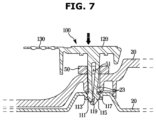
- FIG. 7 is a cross-sectional view illustrating a state in which a pair of fixing pins are elastically deformed by the clamp being inserted into the passing hole of the cable holder and the cable fixing hole of the rear case according to an embodiment of the present disclosure
- FIG. 8 is a cross-sectional view illustrating a state in which a first hook and a second hook are fixed to the cable fixing hole according to an embodiment of the present disclosure
- FIG. 9 is a cross-sectional view illustrating a state in which a force is applied to a handle in order to remove the clamp from the cable fixing hole according to an embodiment of the present disclosure.
- the clamp 100 may include the pair of fixing pins 110 inserted into and fixed to the cable fixing hole 23 , the pressing part 120 to which a force is applied to insert the pair of fixing pins 110 into the cable fixing hole 23 , and the handle 130 to which a force is applied to separate the pair of fixing pins 110 from the cable fixing hole 23 .
- the pair of fixing pins 110 may be provided to be elastically deformable.
- the pair of fixing pins 110 may include a first hook 111 provided at an end of one of the pair of fixing pins 110 , and a second hook 115 provided at an end of the other one of the pair of fixing pins 110 .
- the first hook 111 may include a first protruding portion 113 provided to protrude in a radial direction of the cable fixing hole 23 .
- the first protruding portion 113 may be fixed to the cable fixing hole 23 when the pair of fixing pins 110 are inserted into the cable fixing hole 23 .
- the second hook 115 may include a second protruding portion 117 provided to protrude in the radial direction of the cable fixing hole 23 , and a concave portion 119 provided to be depressed in the radial direction of the cable fixing hole 23 on an opposite surface of the second protruding portion 117 .
- the second protruding portion 117 may be fixed to the cable fixing hole 23 when the pair of fixing pins 110 are inserted into the cable fixing hole 23 .
- the second protruding portion 117 may be provided to protrude further in the radial direction of the cable fixing hole 23 than the first protruding portion 113 .
- a fixing force of the second hook 115 fixed to the cable fixing hole 23 by the second protruding portion 117 may be greater than that of the first hook 111 .
- the fixing force may refer to a force required to release the first hook 111 and the second hook 115 from the cable fixing hole 23 when the first hook 111 and the second hook 115 are fixed to the cable fixing hole 23 .
- first protruding portion 113 of the first hook 111 protrudes relatively smaller than the second protruding portion 117 of the second hook 115 , when the pair of fixing pins 110 are inserted into and fixed to the cable fixing hole 23 , the pair of fixing pins 110 may be easily inserted and fixed.
- the pair of fixing pins 110 may be provided to have an outer diameter equal to or smaller than inner diameters of the passing hole 51 and the cable fixing hole 23 to be easily inserted into the passing hole 51 of the cable holder 50 and the cable fixing hole 23 of the rear case 20 .
- the inner diameter of the passing hole 51 may be larger than or equal to the inner diameter of the cable fixing hole 23 .
- the first hook 111 and the second hook 115 may protrude to have an outer diameter larger than the inner diameter of the cable fixing hole 23 so that the pair of fixing pins 110 may be fixed to the cable fixing hole 23 by being inserted into the passing hole 51 and the cable fixing hole 23 . That is, the first protruding portion 113 and the second protruding portion 117 may protrude to have outer diameters larger than the inner diameter of the cable fixing hole 23 .
- the pair of fixing pins 110 may be elastically deformed so that the outer diameters of the first hook 111 and the second hook 115 decrease.
- the first hook 111 and the second hook 115 may be elastically deformed to return to the original outer diameter.
- the first protruding portion 113 and the second protruding portion 117 may be fixed to the cable fixing hole 23 .
- the pressing part 120 may be provided above the pair of fixing pins 110 .
- a force is applied to an upper end of the pressing part 120 in a direction in which the pair of fixing pins 110 are inserted into the cable fixing hole 23 .
- the handle 130 may be provided to extend from one side of the pressing part 120 adjacent to the first hook 111 in the first hook 111 and the second hook 115 .
- a force is applied to a lower end of the handle 130 in a direction in which the pair of fixing pins 110 are separated from the cable fixing hole 23 .
- the reason that the handle 130 extends from one side of the pressing part 120 adjacent to the first hook 111 is that the first hook 111 may be released from the cable fixing hole 23 with a smaller force than the second hook 115 .
- this is to cause more elastic deformation to occur in the second hook 115 than in the first hook 111 in order to easily release the second hook 115 which requires a great force to be released from the cable fixing hole 23 .
- the clamp 100 may be positioned above the passing hole 51 and the case fixing hole 23 .
- a user may press the upper end of the pressing part 120 .
- the first hook 111 and the second hook 115 may be inserted into the passing hole 51 and the cable fixing hole 23 by being elastically deformed so that the outer diameters thereof decrease.
- the first protruding portion 113 and the second protruding portion 117 may come into contact with inner walls of the passing hole 51 and the cable fixing hole 23 .
- the force applied to the pressing part 120 may be substantially 1 kgf.
- the first hook 111 and the second hook 115 may pass through the cable fixing hole 23 .
- the first protruding portion 113 and the second protruding portion 117 may not be in contact with the inner walls of the passing hole 51 and the cable fixing hole 23 .
- the first protruding portion 113 and the second protruding portion 117 are not in contact with the inner walls of the passing hole 51 and the cable fixing hole 23 , the first hook 111 and the second hook 115 may be elastically deformed so that the outer diameters thereof increase as much as the original outer diameters.
- the first protruding portion 113 and the second protruding portion 117 may be fixed to the cable fixing hole 23 .
- the fixing force of the clamp 100 may increase.
- the fixing force may be substantially 13 kgf.
- the fixing force of the clamp 100 increases, even when the cable 30 is pulled, the clamp 100 may not be easily separated. Accordingly, the cable 30 may be maintained in a state of being fixed to the rear case 20 .
- the user may raise the handle 130 .
- a force may be applied to the lower end of the handle 130 in the direction in which the pair of fixing pins 110 are separated from the cable fixing hole 23 .
- the first protruding portion 113 may be easily released from the cable fixing hole 23 .
- the second hook 115 When the first hook 111 is released from the cable fixing hole 23 by being elastically deformed, the second hook 115 may be elastically deformed so that the concave portion 119 may move to a position for receiving an opposite surface of the first protruding portion 113 of the first hook 111 . When the second hook 115 is elastically deformed, the second protruding portion 117 may be released from the cable fixing hole 23 .
- the clamp 100 may be separated from the cable fixing hole 23 as illustrated in FIG. 6 .
- the force applied to the handle 130 may be substantially 1 kgf.
Landscapes
- Engineering & Computer Science (AREA)
- Microelectronics & Electronic Packaging (AREA)
- General Engineering & Computer Science (AREA)
- Theoretical Computer Science (AREA)
- Signal Processing (AREA)
- Multimedia (AREA)
- Computer Hardware Design (AREA)
- Human Computer Interaction (AREA)
- Physics & Mathematics (AREA)
- General Physics & Mathematics (AREA)
- Insertion, Bundling And Securing Of Wires For Electric Apparatuses (AREA)
- Devices For Indicating Variable Information By Combining Individual Elements (AREA)
- Installation Of Indoor Wiring (AREA)
Abstract
Description
Claims (15)
Applications Claiming Priority (3)
| Application Number | Priority Date | Filing Date | Title |
|---|---|---|---|
| KR10-2019-0097589 | 2019-08-09 | ||
| KR1020190097589A KR20210017789A (en) | 2019-08-09 | 2019-08-09 | Display apparatus |
| PCT/KR2019/015114 WO2021029487A1 (en) | 2019-08-09 | 2019-11-08 | Display device |
Related Parent Applications (1)
| Application Number | Title | Priority Date | Filing Date |
|---|---|---|---|
| PCT/KR2019/015114 Continuation WO2021029487A1 (en) | 2019-08-09 | 2019-11-08 | Display device |
Publications (2)
| Publication Number | Publication Date |
|---|---|
| US20220159855A1 US20220159855A1 (en) | 2022-05-19 |
| US12069824B2 true US12069824B2 (en) | 2024-08-20 |
Family
ID=74569430
Family Applications (1)
| Application Number | Title | Priority Date | Filing Date |
|---|---|---|---|
| US17/667,309 Active 2040-09-30 US12069824B2 (en) | 2019-08-09 | 2022-02-08 | Display apparatus |
Country Status (4)
| Country | Link |
|---|---|
| US (1) | US12069824B2 (en) |
| EP (1) | EP3993581B1 (en) |
| KR (1) | KR20210017789A (en) |
| WO (1) | WO2021029487A1 (en) |
Citations (43)
| Publication number | Priority date | Publication date | Assignee | Title |
|---|---|---|---|---|
| US3345706A (en) | 1965-10-22 | 1967-10-10 | Illinois Tool Works | Clips for mounting rods and the like on panels |
| DE2300731A1 (en) | 1972-01-08 | 1973-07-19 | Hideo Umezu | RIBBED FASTENING TAPE MADE OF PLASTIC |
| FR2259273A1 (en) | 1974-01-24 | 1975-08-22 | Sonofam | Clip for trim attachment to sheet materials - has inclined surfaces of hook engaging edge of hole in sheet |
| GB2090907A (en) | 1980-11-28 | 1982-07-21 | Nissan Motor | Harness clip |
| JPH08294216A (en) | 1995-04-20 | 1996-11-05 | Nec Data Terminal Ltd | Cable clamp and clamping method of cable |
| JP2001007564A (en) | 1999-06-25 | 2001-01-12 | Kitagawa Ind Co Ltd | Fixture and auxiliary fixture |
| US20040047115A1 (en) * | 2002-09-05 | 2004-03-11 | Helot Jacques H. | Display units |
| US20040238199A1 (en) * | 2003-05-27 | 2004-12-02 | Sharp Kabushiki Kaisha | Connecting apparatus, image scanning apparatus, and image forming system |
| US20050141180A1 (en) * | 2003-12-25 | 2005-06-30 | Kouji Umeda | Display unit with cord clamper |
| US20050272297A1 (en) | 2004-06-08 | 2005-12-08 | Bong-Ju Lee | Connector device and display device using the same |
| KR20060002175A (en) | 2004-07-01 | 2006-01-09 | 기아자동차주식회사 | Car hood open device to protect pedestrians |
| US20060016937A1 (en) * | 2004-04-30 | 2006-01-26 | Airbus Deutschland Gmbh | Suspension clamping holder for a support structure |
| US20060021789A1 (en) * | 2004-07-15 | 2006-02-02 | Sachiko Nishikino | External device and electronic apparatus |
| US7088577B2 (en) * | 2004-03-25 | 2006-08-08 | Dell Products L.P. | System and method for managing information handling system adjustable cables |
| US7097047B2 (en) * | 2003-09-30 | 2006-08-29 | Dell Products L.P. | Cable management flip tray assembly |
| US20070018057A1 (en) * | 2005-07-20 | 2007-01-25 | Zdravko Kovac | Hinged clip having a retainer |
| US7201352B2 (en) * | 2003-02-10 | 2007-04-10 | Newfrey Llc | Cable clamp |
| CN200956632Y (en) | 2006-10-13 | 2007-10-03 | 深圳创维-Rgb电子有限公司 | Cable clamp to secure TV power cord |
| US20090149055A1 (en) * | 2005-11-25 | 2009-06-11 | Mitsubishi Electric Corporation | Connector holding clamp and connector retaining structure |
| JP4289495B2 (en) | 2004-06-02 | 2009-07-01 | 矢崎総業株式会社 | Clamp |
| KR20090076243A (en) | 2008-01-08 | 2009-07-13 | 엘지전자 주식회사 | Display device |
| US20110116218A1 (en) * | 2009-11-18 | 2011-05-19 | Samsung Electronics Co., Ltd. | Display apparatus |
| US20120267487A1 (en) * | 2007-08-28 | 2012-10-25 | Sony Corporation | L-character stand |
| US20130194736A1 (en) * | 2012-01-27 | 2013-08-01 | Fujitsu Frontech Limited | Information processing apparatus |
| US20130284238A1 (en) * | 2012-04-25 | 2013-10-31 | Lg Electronic Inc. | Solar cell module |
| US20130284513A1 (en) * | 2011-10-24 | 2013-10-31 | Clo Systems, Llc. | Cable management system |
| KR101488999B1 (en) | 2008-08-06 | 2015-02-02 | 엘지전자 주식회사 | Display Device |
| US9000299B2 (en) | 2011-07-18 | 2015-04-07 | Prysmian Power Cables And Systems Usa, Llc | Cable clamp having winged flanges |
| US9241419B2 (en) | 2011-12-28 | 2016-01-19 | Tdk Corporation | Bracket and electronic device |
| JP2017032017A (en) | 2015-07-30 | 2017-02-09 | キヤノン株式会社 | Cable holding structure |
| US20170127554A1 (en) * | 2015-11-04 | 2017-05-04 | Fujitsu Component Limited | Console drawer |
| US9915281B2 (en) | 2014-01-31 | 2018-03-13 | Reinke Manufacturing Co., Inc. | Theft-resistant cable clamp |
| US20180187798A1 (en) * | 2015-07-22 | 2018-07-05 | Illinois Tool Works Inc. | Routing clip assembly |
| US10051760B2 (en) * | 2014-10-30 | 2018-08-14 | Fujitsu Component Limited | KVM switch, mounting bracket and system |
| US10106303B2 (en) | 2012-05-08 | 2018-10-23 | Thomas & Betts International Llc | Cable tie head |
| US20190017658A1 (en) | 2017-07-12 | 2019-01-17 | Global Navigation Sciences, Inc. | Assembly with computer interface module |
| US10207460B2 (en) * | 2011-06-02 | 2019-02-19 | A. Raymond Et Cie | Method of making hinged fasteners by three-dimensional printing |
| US20190056058A1 (en) * | 2017-08-16 | 2019-02-21 | Facebook, Inc. | Mounting kit for display device |
| US20190075945A1 (en) | 2017-09-12 | 2019-03-14 | B&G Plastics, Inc. | Ring security display hanger |
| US20190089073A1 (en) | 2016-05-31 | 2019-03-21 | Nifco Inc. | Clip for grounding |
| US10291803B2 (en) * | 2016-09-09 | 2019-05-14 | Canon Kabushiki Kaisha | Image forming apparatus |
| US10955873B1 (en) * | 2019-11-06 | 2021-03-23 | Lenovo (Singapore) Pte. Ltd. | Display device |
| US20220360059A1 (en) * | 2021-05-05 | 2022-11-10 | Shoals Technologies Group, Llc | Solar cable retention clips with resilient hooks for structure mounting |
Family Cites Families (1)
| Publication number | Priority date | Publication date | Assignee | Title |
|---|---|---|---|---|
| KR100621105B1 (en) * | 2004-09-02 | 2006-09-19 | 삼성전자주식회사 | Display device |
-
2019
- 2019-08-09 KR KR1020190097589A patent/KR20210017789A/en not_active Ceased
- 2019-11-08 WO PCT/KR2019/015114 patent/WO2021029487A1/en not_active Ceased
- 2019-11-08 EP EP19941466.5A patent/EP3993581B1/en active Active
-
2022
- 2022-02-08 US US17/667,309 patent/US12069824B2/en active Active
Patent Citations (45)
| Publication number | Priority date | Publication date | Assignee | Title |
|---|---|---|---|---|
| US3345706A (en) | 1965-10-22 | 1967-10-10 | Illinois Tool Works | Clips for mounting rods and the like on panels |
| DE2300731A1 (en) | 1972-01-08 | 1973-07-19 | Hideo Umezu | RIBBED FASTENING TAPE MADE OF PLASTIC |
| FR2259273A1 (en) | 1974-01-24 | 1975-08-22 | Sonofam | Clip for trim attachment to sheet materials - has inclined surfaces of hook engaging edge of hole in sheet |
| GB2090907A (en) | 1980-11-28 | 1982-07-21 | Nissan Motor | Harness clip |
| JPH08294216A (en) | 1995-04-20 | 1996-11-05 | Nec Data Terminal Ltd | Cable clamp and clamping method of cable |
| JP4044705B2 (en) | 1999-06-25 | 2008-02-06 | 北川工業株式会社 | Fixture and auxiliary fixture |
| JP2001007564A (en) | 1999-06-25 | 2001-01-12 | Kitagawa Ind Co Ltd | Fixture and auxiliary fixture |
| US20040047115A1 (en) * | 2002-09-05 | 2004-03-11 | Helot Jacques H. | Display units |
| US7201352B2 (en) * | 2003-02-10 | 2007-04-10 | Newfrey Llc | Cable clamp |
| US20040238199A1 (en) * | 2003-05-27 | 2004-12-02 | Sharp Kabushiki Kaisha | Connecting apparatus, image scanning apparatus, and image forming system |
| US7097047B2 (en) * | 2003-09-30 | 2006-08-29 | Dell Products L.P. | Cable management flip tray assembly |
| US20050141180A1 (en) * | 2003-12-25 | 2005-06-30 | Kouji Umeda | Display unit with cord clamper |
| US7088577B2 (en) * | 2004-03-25 | 2006-08-08 | Dell Products L.P. | System and method for managing information handling system adjustable cables |
| US20060016937A1 (en) * | 2004-04-30 | 2006-01-26 | Airbus Deutschland Gmbh | Suspension clamping holder for a support structure |
| JP4289495B2 (en) | 2004-06-02 | 2009-07-01 | 矢崎総業株式会社 | Clamp |
| US20050272297A1 (en) | 2004-06-08 | 2005-12-08 | Bong-Ju Lee | Connector device and display device using the same |
| KR20060002175A (en) | 2004-07-01 | 2006-01-09 | 기아자동차주식회사 | Car hood open device to protect pedestrians |
| US20060021789A1 (en) * | 2004-07-15 | 2006-02-02 | Sachiko Nishikino | External device and electronic apparatus |
| US20070018057A1 (en) * | 2005-07-20 | 2007-01-25 | Zdravko Kovac | Hinged clip having a retainer |
| US20090149055A1 (en) * | 2005-11-25 | 2009-06-11 | Mitsubishi Electric Corporation | Connector holding clamp and connector retaining structure |
| CN200956632Y (en) | 2006-10-13 | 2007-10-03 | 深圳创维-Rgb电子有限公司 | Cable clamp to secure TV power cord |
| US20120267487A1 (en) * | 2007-08-28 | 2012-10-25 | Sony Corporation | L-character stand |
| KR20090076243A (en) | 2008-01-08 | 2009-07-13 | 엘지전자 주식회사 | Display device |
| KR101488999B1 (en) | 2008-08-06 | 2015-02-02 | 엘지전자 주식회사 | Display Device |
| US20110116218A1 (en) * | 2009-11-18 | 2011-05-19 | Samsung Electronics Co., Ltd. | Display apparatus |
| US10207460B2 (en) * | 2011-06-02 | 2019-02-19 | A. Raymond Et Cie | Method of making hinged fasteners by three-dimensional printing |
| US9000299B2 (en) | 2011-07-18 | 2015-04-07 | Prysmian Power Cables And Systems Usa, Llc | Cable clamp having winged flanges |
| US20130284513A1 (en) * | 2011-10-24 | 2013-10-31 | Clo Systems, Llc. | Cable management system |
| US9241419B2 (en) | 2011-12-28 | 2016-01-19 | Tdk Corporation | Bracket and electronic device |
| US8897003B2 (en) * | 2012-01-27 | 2014-11-25 | Fujitsu Frontech Limited | Information processing apparatus |
| US20130194736A1 (en) * | 2012-01-27 | 2013-08-01 | Fujitsu Frontech Limited | Information processing apparatus |
| US20130284238A1 (en) * | 2012-04-25 | 2013-10-31 | Lg Electronic Inc. | Solar cell module |
| US10106303B2 (en) | 2012-05-08 | 2018-10-23 | Thomas & Betts International Llc | Cable tie head |
| US9915281B2 (en) | 2014-01-31 | 2018-03-13 | Reinke Manufacturing Co., Inc. | Theft-resistant cable clamp |
| US10051760B2 (en) * | 2014-10-30 | 2018-08-14 | Fujitsu Component Limited | KVM switch, mounting bracket and system |
| US20180187798A1 (en) * | 2015-07-22 | 2018-07-05 | Illinois Tool Works Inc. | Routing clip assembly |
| JP2017032017A (en) | 2015-07-30 | 2017-02-09 | キヤノン株式会社 | Cable holding structure |
| US20170127554A1 (en) * | 2015-11-04 | 2017-05-04 | Fujitsu Component Limited | Console drawer |
| US20190089073A1 (en) | 2016-05-31 | 2019-03-21 | Nifco Inc. | Clip for grounding |
| US10291803B2 (en) * | 2016-09-09 | 2019-05-14 | Canon Kabushiki Kaisha | Image forming apparatus |
| US20190017658A1 (en) | 2017-07-12 | 2019-01-17 | Global Navigation Sciences, Inc. | Assembly with computer interface module |
| US20190056058A1 (en) * | 2017-08-16 | 2019-02-21 | Facebook, Inc. | Mounting kit for display device |
| US20190075945A1 (en) | 2017-09-12 | 2019-03-14 | B&G Plastics, Inc. | Ring security display hanger |
| US10955873B1 (en) * | 2019-11-06 | 2021-03-23 | Lenovo (Singapore) Pte. Ltd. | Display device |
| US20220360059A1 (en) * | 2021-05-05 | 2022-11-10 | Shoals Technologies Group, Llc | Solar cable retention clips with resilient hooks for structure mounting |
Non-Patent Citations (4)
| Title |
|---|
| European Search Report dated Jul. 27, 2022 issue in European Application No. 19 94 1466. |
| Google Translation of CN 200956632 (Year: 2024). * |
| International Search Report issued in PCT/KR2019/015114 dated May 7, 2020. |
| QLED Q90R user manual. Samsung Electronics Co., Ltd. Jul. 11, 2019 <URL: https://www/samsung.com/ru/support/model/QE55Q90RAUXRU/> english—6, 7. |
Also Published As
| Publication number | Publication date |
|---|---|
| EP3993581A4 (en) | 2022-08-24 |
| EP3993581A1 (en) | 2022-05-04 |
| EP3993581B1 (en) | 2025-01-01 |
| WO2021029487A1 (en) | 2021-02-18 |
| KR20210017789A (en) | 2021-02-17 |
| US20220159855A1 (en) | 2022-05-19 |
Similar Documents
| Publication | Publication Date | Title |
|---|---|---|
| US8506174B2 (en) | Optical connector | |
| US7621676B2 (en) | Optical connector | |
| US8437120B2 (en) | Image display device | |
| US7661887B2 (en) | Shutter assembly | |
| EP2587290A1 (en) | Optical connector | |
| US7648286B2 (en) | Shutter assembly | |
| US8485736B2 (en) | Optical connector | |
| KR20020064196A (en) | Fiber optic connector module | |
| US8905649B2 (en) | Optical fiber terminal fixing member, optical connector, and optical fiber cable with connector | |
| US20190235183A1 (en) | Optical connector | |
| US20170285274A1 (en) | Optical connector and method for connecting optical fiber cables | |
| WO2019130736A1 (en) | Optical connector | |
| JP2014048609A (en) | Fixing member, and display device | |
| US12069824B2 (en) | Display apparatus | |
| WO2020017255A1 (en) | Optical connector and optical connector replacement component unit | |
| JP6992212B1 (en) | Pin clamps for ferrules, pin clamps with guide pins, and optical connectors | |
| US11249259B2 (en) | Outdoor optical fiber connector | |
| JP4112480B2 (en) | Optical component fixing structure, optical fiber tray, optical component holder | |
| US11988876B2 (en) | Fiber optic connector | |
| JP5128716B2 (en) | Optical connector | |
| JP2020013009A (en) | Optical connector and replacement part unit for optical connector | |
| JP6383451B1 (en) | Optical connector and optical connector manufacturing method | |
| JP2002164673A (en) | Fixing structure | |
| CN114628947A (en) | Plug fixing structure and electronic device with plug anti-pulling function | |
| KR200160160Y1 (en) | Housing Fixing Device for Communication Equipment |
Legal Events
| Date | Code | Title | Description |
|---|---|---|---|
| FEPP | Fee payment procedure |
Free format text: ENTITY STATUS SET TO UNDISCOUNTED (ORIGINAL EVENT CODE: BIG.); ENTITY STATUS OF PATENT OWNER: LARGE ENTITY |
|
| AS | Assignment |
Owner name: SAMSUNG ELECTRONICS CO., LTD., KOREA, REPUBLIC OF Free format text: ASSIGNMENT OF ASSIGNORS INTEREST;ASSIGNORS:KIM, KI HUN;KIM, KYOUNG HWAN;KIM, SEONG SOO;AND OTHERS;REEL/FRAME:058936/0120 Effective date: 20220118 |
|
| STPP | Information on status: patent application and granting procedure in general |
Free format text: DOCKETED NEW CASE - READY FOR EXAMINATION |
|
| STPP | Information on status: patent application and granting procedure in general |
Free format text: NON FINAL ACTION MAILED |
|
| STPP | Information on status: patent application and granting procedure in general |
Free format text: RESPONSE TO NON-FINAL OFFICE ACTION ENTERED AND FORWARDED TO EXAMINER |
|
| STPP | Information on status: patent application and granting procedure in general |
Free format text: NOTICE OF ALLOWANCE MAILED -- APPLICATION RECEIVED IN OFFICE OF PUBLICATIONS |
|
| ZAAA | Notice of allowance and fees due |
Free format text: ORIGINAL CODE: NOA |
|
| ZAAB | Notice of allowance mailed |
Free format text: ORIGINAL CODE: MN/=. |
|
| STPP | Information on status: patent application and granting procedure in general |
Free format text: PUBLICATIONS -- ISSUE FEE PAYMENT RECEIVED |
|
| STPP | Information on status: patent application and granting procedure in general |
Free format text: PUBLICATIONS -- ISSUE FEE PAYMENT VERIFIED |
|
| STCF | Information on status: patent grant |
Free format text: PATENTED CASE |