US12066324B2 - Radiation sensor with an integrated mechanical optical modulator and related manufacturing process - Google Patents
Radiation sensor with an integrated mechanical optical modulator and related manufacturing process Download PDFInfo
- Publication number
- US12066324B2 US12066324B2 US17/530,785 US202117530785A US12066324B2 US 12066324 B2 US12066324 B2 US 12066324B2 US 202117530785 A US202117530785 A US 202117530785A US 12066324 B2 US12066324 B2 US 12066324B2
- Authority
- US
- United States
- Prior art keywords
- detection
- cavity
- movable structure
- shield
- suspended movable
- Prior art date
- Legal status (The legal status is an assumption and is not a legal conclusion. Google has not performed a legal analysis and makes no representation as to the accuracy of the status listed.)
- Active, expires
Links
- 230000005855 radiation Effects 0.000 title claims abstract description 82
- 238000004519 manufacturing process Methods 0.000 title claims description 6
- 230000003287 optical effect Effects 0.000 title description 10
- 238000001514 detection method Methods 0.000 claims abstract description 177
- 230000008859 change Effects 0.000 claims abstract description 6
- 239000004020 conductor Substances 0.000 claims abstract description 6
- 239000004065 semiconductor Substances 0.000 claims description 32
- 238000002161 passivation Methods 0.000 claims description 22
- 239000000463 material Substances 0.000 claims description 12
- 229910021420 polycrystalline silicon Inorganic materials 0.000 claims description 12
- 229920005591 polysilicon Polymers 0.000 claims description 12
- 238000000034 method Methods 0.000 claims description 8
- 238000004806 packaging method and process Methods 0.000 claims description 7
- 230000008569 process Effects 0.000 claims description 7
- 230000004308 accommodation Effects 0.000 claims description 6
- 125000006850 spacer group Chemical group 0.000 claims description 4
- 238000010168 coupling process Methods 0.000 claims description 3
- 238000005859 coupling reaction Methods 0.000 claims description 3
- 239000011248 coating agent Substances 0.000 claims description 2
- 238000000576 coating method Methods 0.000 claims description 2
- 230000008878 coupling Effects 0.000 claims description 2
- 230000002093 peripheral effect Effects 0.000 description 34
- 229910052751 metal Inorganic materials 0.000 description 17
- 239000002184 metal Substances 0.000 description 17
- 238000012512 characterization method Methods 0.000 description 5
- XUIMIQQOPSSXEZ-UHFFFAOYSA-N Silicon Chemical compound [Si] XUIMIQQOPSSXEZ-UHFFFAOYSA-N 0.000 description 4
- 230000008901 benefit Effects 0.000 description 4
- 229910052710 silicon Inorganic materials 0.000 description 4
- 239000010703 silicon Substances 0.000 description 4
- 230000003321 amplification Effects 0.000 description 3
- 238000004891 communication Methods 0.000 description 3
- 238000005530 etching Methods 0.000 description 3
- 238000003199 nucleic acid amplification method Methods 0.000 description 3
- 230000000737 periodic effect Effects 0.000 description 3
- BOTDANWDWHJENH-UHFFFAOYSA-N Tetraethyl orthosilicate Chemical compound CCO[Si](OCC)(OCC)OCC BOTDANWDWHJENH-UHFFFAOYSA-N 0.000 description 2
- 229910045601 alloy Inorganic materials 0.000 description 2
- 239000000956 alloy Substances 0.000 description 2
- 229910052782 aluminium Inorganic materials 0.000 description 2
- XAGFODPZIPBFFR-UHFFFAOYSA-N aluminium Chemical compound [Al] XAGFODPZIPBFFR-UHFFFAOYSA-N 0.000 description 2
- -1 aluminum-germanium Chemical compound 0.000 description 2
- 238000005520 cutting process Methods 0.000 description 2
- JVPLOXQKFGYFMN-UHFFFAOYSA-N gold tin Chemical compound [Sn].[Au] JVPLOXQKFGYFMN-UHFFFAOYSA-N 0.000 description 2
- 230000005693 optoelectronics Effects 0.000 description 2
- BASFCYQUMIYNBI-UHFFFAOYSA-N platinum Chemical compound [Pt] BASFCYQUMIYNBI-UHFFFAOYSA-N 0.000 description 2
- KRHYYFGTRYWZRS-UHFFFAOYSA-N Fluorane Chemical compound F KRHYYFGTRYWZRS-UHFFFAOYSA-N 0.000 description 1
- 229910052581 Si3N4 Inorganic materials 0.000 description 1
- 229910000831 Steel Inorganic materials 0.000 description 1
- RTAQQCXQSZGOHL-UHFFFAOYSA-N Titanium Chemical compound [Ti] RTAQQCXQSZGOHL-UHFFFAOYSA-N 0.000 description 1
- NRTOMJZYCJJWKI-UHFFFAOYSA-N Titanium nitride Chemical compound [Ti]#N NRTOMJZYCJJWKI-UHFFFAOYSA-N 0.000 description 1
- 230000015572 biosynthetic process Effects 0.000 description 1
- 239000003990 capacitor Substances 0.000 description 1
- 238000010586 diagram Methods 0.000 description 1
- 239000011521 glass Substances 0.000 description 1
- PCHJSUWPFVWCPO-UHFFFAOYSA-N gold Chemical compound [Au] PCHJSUWPFVWCPO-UHFFFAOYSA-N 0.000 description 1
- 229910052737 gold Inorganic materials 0.000 description 1
- 239000010931 gold Substances 0.000 description 1
- 239000007769 metal material Substances 0.000 description 1
- 238000012986 modification Methods 0.000 description 1
- 230000004048 modification Effects 0.000 description 1
- 239000011368 organic material Substances 0.000 description 1
- 229910052697 platinum Inorganic materials 0.000 description 1
- 230000001681 protective effect Effects 0.000 description 1
- 230000009467 reduction Effects 0.000 description 1
- 230000035945 sensitivity Effects 0.000 description 1
- HQVNEWCFYHHQES-UHFFFAOYSA-N silicon nitride Chemical compound N12[Si]34N5[Si]62N3[Si]51N64 HQVNEWCFYHHQES-UHFFFAOYSA-N 0.000 description 1
- 238000004513 sizing Methods 0.000 description 1
- 239000010959 steel Substances 0.000 description 1
- 239000000725 suspension Substances 0.000 description 1
- LFQCEHFDDXELDD-UHFFFAOYSA-N tetramethyl orthosilicate Chemical compound CO[Si](OC)(OC)OC LFQCEHFDDXELDD-UHFFFAOYSA-N 0.000 description 1
- 239000010936 titanium Substances 0.000 description 1
- 229910052719 titanium Inorganic materials 0.000 description 1
Images


Classifications
-
- G—PHYSICS
- G01—MEASURING; TESTING
- G01J—MEASUREMENT OF INTENSITY, VELOCITY, SPECTRAL CONTENT, POLARISATION, PHASE OR PULSE CHARACTERISTICS OF INFRARED, VISIBLE OR ULTRAVIOLET LIGHT; COLORIMETRY; RADIATION PYROMETRY
- G01J5/00—Radiation pyrometry, e.g. infrared or optical thermometry
- G01J5/02—Constructional details
-
- G—PHYSICS
- G01—MEASURING; TESTING
- G01J—MEASUREMENT OF INTENSITY, VELOCITY, SPECTRAL CONTENT, POLARISATION, PHASE OR PULSE CHARACTERISTICS OF INFRARED, VISIBLE OR ULTRAVIOLET LIGHT; COLORIMETRY; RADIATION PYROMETRY
- G01J3/00—Spectrometry; Spectrophotometry; Monochromators; Measuring colours
- G01J3/02—Details
- G01J3/0205—Optical elements not provided otherwise, e.g. optical manifolds, diffusers, windows
- G01J3/0232—Optical elements not provided otherwise, e.g. optical manifolds, diffusers, windows using shutters
-
- G—PHYSICS
- G01—MEASURING; TESTING
- G01J—MEASUREMENT OF INTENSITY, VELOCITY, SPECTRAL CONTENT, POLARISATION, PHASE OR PULSE CHARACTERISTICS OF INFRARED, VISIBLE OR ULTRAVIOLET LIGHT; COLORIMETRY; RADIATION PYROMETRY
- G01J1/00—Photometry, e.g. photographic exposure meter
- G01J1/10—Photometry, e.g. photographic exposure meter by comparison with reference light or electric value provisionally void
- G01J1/20—Photometry, e.g. photographic exposure meter by comparison with reference light or electric value provisionally void intensity of the measured or reference value being varied to equalise their effects at the detectors, e.g. by varying incidence angle
- G01J1/34—Photometry, e.g. photographic exposure meter by comparison with reference light or electric value provisionally void intensity of the measured or reference value being varied to equalise their effects at the detectors, e.g. by varying incidence angle using separate light paths used alternately or sequentially, e.g. flicker
- G01J1/36—Photometry, e.g. photographic exposure meter by comparison with reference light or electric value provisionally void intensity of the measured or reference value being varied to equalise their effects at the detectors, e.g. by varying incidence angle using separate light paths used alternately or sequentially, e.g. flicker using electric radiation detectors
-
- G—PHYSICS
- G01—MEASURING; TESTING
- G01J—MEASUREMENT OF INTENSITY, VELOCITY, SPECTRAL CONTENT, POLARISATION, PHASE OR PULSE CHARACTERISTICS OF INFRARED, VISIBLE OR ULTRAVIOLET LIGHT; COLORIMETRY; RADIATION PYROMETRY
- G01J3/00—Spectrometry; Spectrophotometry; Monochromators; Measuring colours
- G01J3/02—Details
- G01J3/027—Control of working procedures of a spectrometer; Failure detection; Bandwidth calculation
-
- G—PHYSICS
- G01—MEASURING; TESTING
- G01J—MEASUREMENT OF INTENSITY, VELOCITY, SPECTRAL CONTENT, POLARISATION, PHASE OR PULSE CHARACTERISTICS OF INFRARED, VISIBLE OR ULTRAVIOLET LIGHT; COLORIMETRY; RADIATION PYROMETRY
- G01J3/00—Spectrometry; Spectrophotometry; Monochromators; Measuring colours
- G01J3/12—Generating the spectrum; Monochromators
- G01J3/18—Generating the spectrum; Monochromators using diffraction elements, e.g. grating
- G01J3/1804—Plane gratings
-
- G—PHYSICS
- G01—MEASURING; TESTING
- G01J—MEASUREMENT OF INTENSITY, VELOCITY, SPECTRAL CONTENT, POLARISATION, PHASE OR PULSE CHARACTERISTICS OF INFRARED, VISIBLE OR ULTRAVIOLET LIGHT; COLORIMETRY; RADIATION PYROMETRY
- G01J3/00—Spectrometry; Spectrophotometry; Monochromators; Measuring colours
- G01J3/28—Investigating the spectrum
- G01J3/2803—Investigating the spectrum using photoelectric array detector
-
- G—PHYSICS
- G02—OPTICS
- G02B—OPTICAL ELEMENTS, SYSTEMS OR APPARATUS
- G02B26/00—Optical devices or arrangements for the control of light using movable or deformable optical elements
- G02B26/02—Optical devices or arrangements for the control of light using movable or deformable optical elements for controlling the intensity of light
- G02B26/04—Optical devices or arrangements for the control of light using movable or deformable optical elements for controlling the intensity of light by periodically varying the intensity of light, e.g. using choppers
-
- H01L33/465—
-
- H—ELECTRICITY
- H10—SEMICONDUCTOR DEVICES; ELECTRIC SOLID-STATE DEVICES NOT OTHERWISE PROVIDED FOR
- H10H—INORGANIC LIGHT-EMITTING SEMICONDUCTOR DEVICES HAVING POTENTIAL BARRIERS
- H10H20/00—Individual inorganic light-emitting semiconductor devices having potential barriers, e.g. light-emitting diodes [LED]
- H10H20/80—Constructional details
- H10H20/862—Resonant cavity structures
-
- G—PHYSICS
- G01—MEASURING; TESTING
- G01J—MEASUREMENT OF INTENSITY, VELOCITY, SPECTRAL CONTENT, POLARISATION, PHASE OR PULSE CHARACTERISTICS OF INFRARED, VISIBLE OR ULTRAVIOLET LIGHT; COLORIMETRY; RADIATION PYROMETRY
- G01J1/00—Photometry, e.g. photographic exposure meter
- G01J1/10—Photometry, e.g. photographic exposure meter by comparison with reference light or electric value provisionally void
- G01J1/20—Photometry, e.g. photographic exposure meter by comparison with reference light or electric value provisionally void intensity of the measured or reference value being varied to equalise their effects at the detectors, e.g. by varying incidence angle
- G01J1/34—Photometry, e.g. photographic exposure meter by comparison with reference light or electric value provisionally void intensity of the measured or reference value being varied to equalise their effects at the detectors, e.g. by varying incidence angle using separate light paths used alternately or sequentially, e.g. flicker
- G01J1/36—Photometry, e.g. photographic exposure meter by comparison with reference light or electric value provisionally void intensity of the measured or reference value being varied to equalise their effects at the detectors, e.g. by varying incidence angle using separate light paths used alternately or sequentially, e.g. flicker using electric radiation detectors
- G01J2001/363—Chopper stabilisation
Definitions
- the present disclosure relates to a radiation sensor with an integrated mechanical optical modulator, as well as to a corresponding manufacturing process.
- FIG. 1 shows a sensor 1 and a characterization system 2 , which includes: an optical source 4 which simulates a black body and emits radiation; an optical modulator 6 of mechanical type (i.e., a shutter), which is also known as a chopper 6 and is configured to receive the radiation emitted by the optical source 4 and to transmit a test radiation; an optical circuit 8 , configured to receive the test radiation and to direct it to the sensor 1 , so that the latter generates a corresponding electrical signal; and an amplification and control circuitry 10 , which receives the electrical signal and amplifies it, generating a corresponding output signal which may be used for the characterization, and further controls the chopper 6 , to ensure the correct timing of the chopper 6 .
- the amplification and control circuitry 10 comprises a so-called lock-in amplifier.
- the chopper 6 of mechanical type, allows the intensity of the test radiation to be modulated, in such a way that the electrical signal generated by the sensor 1 is in translated band; in this manner, the output signal generated by the amplification and control circuitry 10 benefits from a greater resilience with respect to, for example, the optical noise.
- Embodiments are directed to a radiation sensor, a device comprising a radiation sensor, and manufacturing processes for forming same.
- FIG. 1 shows a block diagram of a characterization system of known type
- FIGS. 2 and 4 schematically show a cross-section of a radiation sensor, in two different operating conditions
- FIG. 3 schematically shows a top view of a portion of the sensor shown in FIG. 2 ;
- FIGS. 5 , 6 and 8 schematically show cross-sections of radiation sensors
- FIG. 7 shows the trend of the wavelength of the radiation impinged on a detection device, as the position of the detection device varies along an axis
- FIG. 9 schematically shows a cross-section of a package containing a sensor
- FIGS. 10 - 16 schematically show cross-sections of a sensor, during subsequent steps of a manufacturing process.
- FIG. 17 a cross-section of a radiation sensor in accordance with another embodiment.
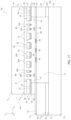
- FIG. 2 shows a sensor 12 , which comprises a first outer body 14 , a second outer body 16 and an intermediate body 18 .
- the first outer body 14 is formed, for example, by a semiconductor material (e.g., silicon) and is delimited at the top and at the bottom by a top surface S 14t and a bottom surface S 14b , respectively.
- the top and bottom surfaces, and other orientation terms used herein, are being used to refer to the orientation of the outer body 14 (or the sensor and device) as presented in the drawing.
- the second outer body 16 is formed, for example, by a semiconductor material (e.g., silicon) and is delimited at the top and at the bottom by a respective top surface S 16t and by a respective bottom surface S 16b .
- the intermediate body 18 is formed, for example, by a semiconductor material (e.g., silicon) and is delimited at the top and at the bottom by a respective top surface S 18t and by a respective bottom surface S 18b .
- the sensor 12 further comprises a dielectric region 20 , which is formed for example by TEOS (Tetraethyl orthosilicate) oxide and extends below the first outer body 14 , in direct contact with the bottom surface S 14b .
- the dielectric region 20 laterally delimits a cavity 21 , which is delimited at the top by the first outer body 14 , and hereinafter referred to as the first actuation half-cavity 21 .
- the sensor 12 further comprises an intermediate region 22 , which is formed for example by polysilicon and extends below the dielectric region 20 , being in direct contact therewith.
- the intermediate region 22 comprises: a peripheral portion 23 , which extends in direct contact with the overlying dielectric region 20 ; an inner portion which forms a corresponding suspended region 24 ; and a first and a second intermediate portion 25 A, 25 B, which are arranged in a symmetrical manner with respect to the suspended region 24 , in such a way that each of the first and the second intermediate portions 25 A, 25 B is interposed between a respective end of the suspended region 24 and the peripheral portion 23 .
- the suspended region 24 extends below the first actuation half-cavity 21 and is surrounded by the peripheral portion 23 , being fixed thereto through the first and the second intermediate portions 25 A, 25 B, which form a first and a second spring M 1 , M 2 , respectively.
- the intermediate region 22 is delimited at the top by a respective top surface S 22t , which contacts the dielectric region 20 , and is delimited at the bottom by a respective bottom surface S 22 b.
- the sensor 12 further comprises an inner metal region 32 , which is formed for example by aluminum, and extends below the intermediate region 22 , being in direct contact therewith.
- the inner metal region 32 comprises: a respective peripheral portion 33 , which extends in direct contact with the overlying peripheral portion 23 of the intermediate region 22 ; a respective inner portion, which forms a corresponding main shield 34 ; a respective first intermediate portion 35 A and a respective second intermediate portion 35 B, which are arranged in a symmetrical manner with respect to the main shield 34 , in such a way that each of the first and the second intermediate portions 35 A, 35 B is interposed between a respective end of the main shield 34 and the peripheral portion 33 .
- the main shield 34 extends below the suspended region 24 , being in direct contact therewith, and is fixed laterally to the peripheral portion 33 of the inner metal region 32 through the first and the second intermediate portions 35 A, 35 B of the inner metal region 32 .
- the main shield 34 has a grating shape, which is holed.
- the main shield 34 has a planar shape and comprises a plurality of bars 34 A, which, without any loss of generality, are elongated along a Y-direction and are arranged in succession along an X-direction, perpendicular with respect to the Y-direction. Furthermore, the main shield 34 comprises first and second elongated portions 34 B, 34 C, which extend in parallel with the X-axis, are offset along the Y-axis, and are arranged so that each bar 34 A has a first end fixed to the first elongated portion 34 B and a second end fixed to the second elongated portion 34 C.
- the suspended region 24 entirely covers the main shield 34 and is traversed by a plurality of holes 37 , which face at the top the first actuation half-cavity 21 .
- the suspended region 24 comprises first and second elongated portions 24 B, 24 C, which extend in parallel with the X-axis, and a plurality of bar portions 24 A.
- the first and the second elongated portions 24 B, 24 C of the suspended region 24 extend above the first and the second elongated portions 34 B, 34 C of the main shield 34 , respectively, while each bar portion 24 A of the suspended region 24 extends above a corresponding bar 34 A of the main shield 34 .
- Each bar 34 A leaves exposed part of the portion of the bottom surface S 22b delimited by the overlying bar portion 24 A; similarly, the first and the second intermediate portions 35 A, 35 B of the inner metal region 32 leave exposed parts of the portions of bottom surface S 22b delimited by the first and the second intermediate portions 25 A, 25 B of the intermediate region 22 , respectively.
- the sensor 12 further comprises a passivation region 42 , which is formed for example by silicon nitride and comprises: a respective peripheral portion 43 , which extends in direct contact with the overlying peripheral portion 33 of the inner metal region 32 ; a respective inner portion 44 , which extends in direct contact with the overlying main shield 34 , to coat the latter and the parts of the portion of the bottom surface S 22b delimited by the bar portions 24 A left exposed by the underlying bars 34 A of the main shield 34 ; a respective first intermediate portion 45 A and a respective second intermediate portion 45 B, which are arranged in a symmetrical manner with respect to the inner portion 44 , in such a way that each of the first and the second intermediate portions 45 A, 45 B is interposed between a respective end of the inner portion 44 and the peripheral portion 43 .
- a passivation region 42 which is formed for example by silicon nitride and comprises: a respective peripheral portion 43 , which extends in direct contact with the overlying peripheral portion 33 of the inner metal region 32
- the first and the second intermediate portions 45 A, 45 B of the passivation region 42 are arranged below the first and the second intermediate portions 35 A, 35 B of the inner metal region 32 , respectively, to also coat the portions of the bottom surface S 22b formed by the first and the second intermediate portions 25 A, 25 B of the intermediate region 22 and left exposed by the first and the second intermediate portions 35 A, 35 B of the inner metal region 32 .
- the first intermediate portion 35 A of the inner metal region 32 forms the first spring M 1 with the first intermediate portion 25 A of the intermediate region 22 and the first intermediate portion 45 A of the passivation region 42 ;
- the second intermediate portion 35 B of the inner metal region 32 forms the second spring M 2 with the second intermediate portion 25 B of the intermediate region 22 and the second intermediate portion 45 B of the passivation region 42 .
- the inner portion 44 of the passivation region 42 and the suspended region 24 encapsulate the main shield 34 . Furthermore, the holes 37 also extend through the inner portion 44 of the passivation region 42 .
- the sensor 12 further comprises a first bonding region 50 , which is formed for example by glassfrit or by an (e.g., gold-tin or aluminum-germanium) alloy and extends below the peripheral portion 43 of the passivation region 42 , being in direct contact therewith. Furthermore, the first bonding region 50 laterally delimits a cavity 51 , hereinafter referred to as the second actuation half-cavity 51 ; the second actuation half-cavity 51 extends below the inner portion 44 and the first and the second intermediate portions 45 A, 45 B of the passivation region 42 .
- the suspended region 24 , the main shield 34 and the inner portion 44 of the passivation region 42 form a suspended movable structure 55 , which is interposed between the first and the second actuation half-cavities 21 , 51 , which are put in fluidic communication with each other by the holes 37 , which face at the bottom the second actuation half-cavity 51 , in such a way that the first and the second actuation half-cavities 21 , 51 form a main cavity 61 ; the suspended movable structure 55 is held in suspension by the first and the second springs M 1 , M 2 , inside the main cavity 61 .
- the suspended movable structure 55 has a periodic shape along the X-axis, that is each section in parallel with the XZ-plane and passing through the bars 34 A has a periodic shape in parallel with the X-axis; in other words, in each of these sections, both the main shield 34 , the bar portions 24 A and the inner portion 44 of the passivation region 42 have a periodic shape.
- the senor 12 further comprises a plurality of movable actuation elements 63 and a plurality of fixed actuation elements 65 , which are formed by the same material as the intermediate region 22 (e.g., polysilicon), being coplanar therewith, have elongated shapes in parallel with the Y-axis and are interdigitated to each other.
- the intermediate region 22 e.g., polysilicon
- the fixed actuation elements 65 extend cantilevered in the direction of the suspended region 24 , from the peripheral portion 23 of the intermediate region 22 , forming a single piece therewith.
- the peripheral portion 23 of the intermediate region 22 has a hollow shape, which surrounds the suspended region 24 and the first and the second intermediate portions 25 A, 25 B of the intermediate region 22 .
- Each fixed actuation element 65 has a respective first end, which is fixed to the peripheral portion 23 of the intermediate region 22 , and a respective second end, which extends towards the suspended region 24 , without contacting the latter.
- the fixed actuation elements 65 are divided into two groups, which are arranged in a symmetrical manner with respect to the suspended movable structure 55 .
- each movable actuation element 63 extend cantilevered in the direction of the peripheral portion 23 of the intermediate region 22 , from the suspended region 24 , forming a single piece therewith.
- each movable actuation element 63 has a respective first end, which is fixed to the suspended region 24 , and a respective second end, which extends towards the peripheral portion 23 of the intermediate region 22 .
- the movable actuation elements 63 are divided into two groups, which are arranged in a symmetrical manner with respect to the suspended movable structure 55 ; the movable actuation elements 63 of the first group are interdigitated with the first group of fixed actuation elements 65 , while the movable actuation elements 63 of the second group are interdigitated with the second group of fixed actuation elements 65 .
- the senor 12 further comprises, for each movable actuation element 63 , a corresponding movable conductive region 67 , which has an elongated shape in parallel with the Y-axis, is arranged below the movable actuation element 63 and forms a single piece with the main shield 34 .
- the sensor 12 further comprises, for each fixed actuation element 65 , a corresponding fixed conductive region 69 , which has an elongated shape in parallel with the Y-axis and is arranged below the fixed actuation element 65 .
- the movable 67 and fixed conductive regions 69 may be formed, for example, by the same material that forms the inner metal region 32 .
- the movable 67 and fixed conductive regions 69 may be coated at the bottom by corresponding protective regions formed by the same material that forms the passivation region 42 .
- the sensor 12 further comprises terminals which allow the movable conductive regions 67 and the fixed conductive regions 69 to be biased with variable voltages, which act as facing plates of a variable capacitor, to apply an electrostatic force that moves the suspended movable structure 55 in parallel with the X-axis; this movement is allowed by the fact that the first and the second springs M 1 , M 2 are yielding along the X-axis.
- the movement of the suspended movable structure 55 entails the movement, in parallel with the X-axis, of the main shield 34 .
- the movable conductive regions 67 and the fixed conductive regions 69 may be biased, for example, through conductive paths that include so-called through silicon vias (TSV) and traverse the first outer body 14 , the dielectric region 20 and the intermediate region 22 .
- TSV through silicon vias
- the movable conductive regions 67 and the fixed conductive regions 69 are electrically separated; to this end, although not shown, at least part of the peripheral portion 23 of the intermediate region 22 may have a reduced doping (e.g., may be of intrinsic type); additionally or alternatively, dielectric separating regions (not shown), arranged to electrically separate the fixed conductive regions 69 from the peripheral portion 33 of the inner metal region 32 , which is in electrical contact with the movable conductive regions 67 , may extend through the peripheral portion 23 of the intermediate region 22 .
- the sensor 12 further comprises a second bonding region 64 , which is formed for example by glassfrit or by an (e.g., gold-tin or aluminum-germanium) alloy and is interposed between the bottom surface S 18b of the intermediate body 18 and the top surface S 16t of the second outer body 16 , being in direct contact therewith.
- a second bonding region 64 which is formed for example by glassfrit or by an (e.g., gold-tin or aluminum-germanium) alloy and is interposed between the bottom surface S 18b of the intermediate body 18 and the top surface S 16t of the second outer body 16 , being in direct contact therewith.
- the intermediate body 18 and the second bonding region 64 are traversed by a further cavity 71 , hereinafter referred to as the detection cavity 71 .
- the detection cavity 71 extends between the top surface S 18t of the intermediate body 18 and the top surface S 16t of the second outer body 16 .
- the sensor 12 further comprises a detection structure 80 , which is interposed between the second actuation half-cavity 51 and the detection cavity 71 .
- the detection structure 80 comprises a bearing structure 90 , which is suspended above the detection cavity 71 , therefore extends between the detection cavity 71 and the second actuation half-cavity 51 , below the suspended movable structure 55 .
- the sensor 12 comprises a peripheral structure 92 , which is interposed between the intermediate body 18 and the first bonding region 50 ; in particular, the peripheral structure 92 surrounds the bearing structure 90 .
- the bearing structure 90 is constrained (e.g., fixed) laterally to the peripheral structure 92 .
- the bearing structure 90 and the peripheral structure 92 are coplanar.
- each of the bearing structure 90 and the peripheral structure 92 may be formed, for example, by one or more dielectric layers, having conductive or semiconductive regions (not shown) also possibly extending therein.
- the senor 12 comprises a number of detection devices 94 (qualitatively shown in FIG. 2 ), which are integrated in the bearing structure 90 .
- the sensor 12 may comprise an array of detection devices 94 , which therefore have a planar arrangement and are photodetectors capable of varying corresponding electrical quantities according to the radiation impinged thereon.
- each detection device 94 is formed, for example, by a device chosen from among: a corresponding thermocouple; a corresponding thermopile (i.e., a plurality of thermocouples connected in series or in parallel); a corresponding TMOS sensor, i.e., a sensor of CMOS-SOI type; a corresponding bolometer.
- a corresponding thermocouple i.e., a thermopile (i.e., a plurality of thermocouples connected in series or in parallel); a corresponding TMOS sensor, i.e., a sensor of CMOS-SOI type; a corresponding bolometer.
- Each detection device 94 therefore comprises a respective active area, which is sensitive to the impinged radiation.
- the arrangement of the detection devices 94 with respect to the bearing structure 90 is such that the following occurs.
- the detection devices 94 are laterally offset with respect to the main shield 34 , that is as a first approximation are arranged in such a way that the respective active areas are vertically aligned to corresponding holes 37 .
- the active areas of the detection devices 94 are laterally offset with respect to the bars 34 A of the main shield 34 ; in other words, the projections along a Z-axis (perpendicular with respect to the X- and Y-axes) of the bars 34 A do not intercept the active areas of the detection devices 94 .
- the first operating mode of the sensor 12 may correspond to the case in which the movable conductive regions 67 and the fixed conductive regions 69 are free of bias, in such a way that the suspended movable structure 55 is in rest position.
- the movable conductive regions 67 and the fixed conductive regions 69 may also be biased in such a way that the sensor 12 operates in a second operating condition, shown in FIG. 4 , wherein, with respect to the rest position, the suspended movable structure 55 is translated along the X-axis, in such a way that, as a first approximation, the active areas of the detection devices 94 are vertically aligned to corresponding bars 34 A of the main shield 34 , which act as electromagnetic shields.
- the bars 34 A of the main shield 34 may entirely shield the corresponding detection devices 94 ; in other words, the projection along the Z-axis of each bar 34 A entirely covers the active area of the corresponding detection device 94 .
- the possibility of switching between the first and the second operating modes causes the sensor 12 to implement a chopper functionality; this chopper is represented by the suspended movable structure 55 and is therefore integrated with the detection devices 94 , allowing to avoid having to resort to an outer chopper during the characterization procedure of the sensor 12 .
- the sensor 12 further comprises a further shield 99 , hereinafter referred to as the secondary shield 99 .
- the secondary shield 99 is optional.
- FIG. 17 shows a sensor 12 a that is structurally and functionally identically to the sensor 12 of FIG. 2 , except that the sensor 12 a of FIG. 17 does not include the secondary shield 99 .
- the secondary shield 99 is formed by metal material (e.g., aluminum or gold or platinum) and extends above the top surface S 14t of the first outer body 14 .
- the secondary shield 99 is formed by a single piece and is holed, that is includes a plurality of openings A 99 , through which the radiation may pass; although not shown, the secondary shield 99 may have, for example, a grating shape.
- the secondary shield 99 is laterally offset with respect to the detection devices 94 , that is the projection along the Z-axis of the secondary shield 99 falls outside the active areas of the detection devices 94 ; correspondingly, the projections along the Z-axis of the openings A 99 fall on corresponding detection devices 94 . Furthermore, when the sensor 12 operates in the first operating mode, the secondary shield 99 overlies, from a distance, the main shield 34 ; in particular, without any loss of generality, the projection along the Z-axis of the secondary screen 99 falls on the main shield 34 .
- the presence of the secondary shield 99 does not modify the behavior of the sensor 12 as regards the radiation having a normal impingement, with respect to what has been described hereinabove.
- the shape and the arrangement of the secondary shield 99 may be chosen according to a different impingement angle of the radiation, for example in order to optimize the shielding of the active areas of the detection devices 94 during the second operating mode, that is integrating the shielding offered by the main shield 34 .
- the movable conductive regions 67 and the fixed conductive regions 69 may be biased in such a way that the sensor 12 operates in an intermediate operating mode between the first and the second operating modes, that is so that the suspended movable structure 55 assumes an intermediate position between the rest position and the position assumed when the sensor 12 operates in the second operating mode; in this case, the active areas of the detection devices 94 may be partially shielded from the projections along the Z-axis of the bars 34 A of the main shield 34 . In practice, the extent of the shielding, by the main shield 34 , of the active areas of the detection devices 94 may be modulated in a gradual manner.
- the main shield 34 may shield part of the detection devices 94 also in the first operating mode, that is the projection of the main shield 34 along the Z-axis may fall partially into the active areas of the detection devices 94 .
- the main shield 34 only partially shields the detection devices 94 in the second operating mode.
- embodiments are also possible wherein the projection of the secondary shield 99 along the Z-axis falls partially into the active areas of the detection devices 94 . More generally, embodiments are possible wherein, even for radiation with normal impingement, the shielding of the detection devices 94 depends on the mutual positioning of the suspended movable structure 55 with respect to the secondary shield 99 ; in this case, the maximum shielding may be obtained for a certain position of the suspended movable structure 55 , comprised between the positions assumed in the first and the second operating conditions.
- shieldings of desired extent may be obtained for the detection devices 94 , against radiation coming from a given impingement angle and for different positions assumed by the suspended movable structure 55 , through a suitable choice of the shapes and arrangements of the main shield 34 and of the secondary shield 99 .
- the chopper assembly 101 has an extension along the X-axis which is smaller with respect to the extension of the second outer body 16 and of the intermediate body 18 , which together with the second bonding region 64 , the detection structure 80 and the peripheral structure 92 , form a detection assembly 102 . Furthermore, as a first approximation (i.e., neglecting the possible movements along the X-axis), the suspended movable structure 55 is vertically aligned with the underlying detection structure 80 . More precisely, the suspended movable structure 55 may assume at least one position wherein the projection along the Z-axis of at least one part of the main shield 34 falls into the active area of a detection device 94 , shielding it from radiation with normal impingement.
- the detection cavity 71 is absent, in which case the bearing structure (here indicated by 190 ) of the detection structure (here indicated by 180 ) is arranged on the intermediate body 18 , being integrated therewith.
- the detection devices here indicated by 194
- the detection structure 180 may form, for example, a charge-coupling device (CCD).
- CCD charge-coupling device
- the second outer body 16 may be absent; furthermore, the detection cavity 71 may not be entirely closed at the top by the detection structure, which may thus have openings (not shown) which put the detection cavity 71 in communication with the second actuation half-cavity 51 .
- the possible presence of the second outer body 16 allows however the detection cavity 71 to be closed at the bottom, in such a way that the cavity formed as a whole by the detection cavity 71 and by the main cavity 61 is hermetically closed, with advantages in terms of detection sensitivity.
- the fact that at least the main cavity 61 , having the suspended movable structure 55 moving therein, is hermetically closed and under vacuum means that the movement of the suspended movable structure 55 is not hindered by the friction with the air.
- FIG. 6 shows a further embodiment, which is now described limitedly to the differences with respect to FIG. 2 ; reference numbers already used in FIG. 2 are maintained, unless otherwise specified.
- the senor here indicated by 212
- the chopper assembly 101 the detection assembly, here indicated by 202
- the secondary shield 99 the suspended movable structure 55 acts as a diffraction grating.
- the detection unit 202 still comprises the intermediate body, here indicated by 218 , whose top surface S 218t is glued to the first bonding region 50 . Furthermore, the peripheral structure (indicated by 292 ) and the detection structure (indicated by 280 ) extend below the bottom surface S 218b of the intermediate body 218 .
- the detection structure 280 extends below the detection cavity, here indicated by 271 .
- the detection cavity 271 still extends through the intermediate body 218 and is open at the top, to communicate with the overlying second actuation half-cavity 51 .
- the main cavity, here indicated by 261 comprises, in addition to the first and the second actuation half-cavities 21 , 51 , also the underlying detection cavity 271 and is closed at the bottom by the detection structure 280 .
- the peripheral structure 292 which surrounds the detection structure 280 , is bonded to the underlying second bonding region 64 , having the second outer body 16 therebelow.
- the second bonding region 64 laterally delimits an additional cavity 275 , which is closed at the top by the detection structure 280 and is closed at the bottom by the second outer body 16 .
- the detection structure 280 is interposed between the main cavity 261 and the additional cavity 275 .
- the detection structure 280 may include openings such that the main cavity 261 and the additional cavity 275 are in fluidic communication with each other.
- the detection structure 280 is laterally offset with respect to the overlying suspended movable structure 55 .
- the detection structure 280 is laterally offset to the left (with reference to the orientation of FIG. 6 ) with respect to the suspended movable structure 55 .
- this distance is increased, with the same sensor size, with respect to what occurs in the embodiment shown in FIG. 2 , because the detection structure 280 extends below the intermediate body 218 .
- the suspended movable structure 55 performs in space a chromatic scattering of the radiation impinged thereon. Furthermore, the main shield 34 continues to act as a chopper. In this manner, the sensor 212 has the following optical behavior.
- the senor 212 may be sized to act as a spectrometer.
- this offset wx may be sized so that the detection device 94 receives radiation with a wavelength that falls into a corresponding wavelength range.
- detection devices 94 they may be of the same type described with reference to FIG. 2 .
- the intensity of the radiation impinged on the detection devices 94 may be modulated through the controlled movement of the suspended movable structure 55 and the resulting variation of the position of the main shield 34 with respect to the secondary shield 99 , as a first approximation without altering the corresponding wavelength bandwidths.
- the wavelength bandwidth associated with each detection device 94 does not vary as the position along the X-axis of the suspended movable structure 55 varies.
- variable alignment between the main shield 34 and the secondary shield 99 allows modulating the intensity of the radiation exiting the suspended movable structure 55 (and therefore modulating the transmissivity of the set formed by the main shield 34 and the secondary shield 99 ) and therefore affects the intensity of the radiation impinged on the detection devices 94 , but not on the wavelength.
- the variable alignment between the main shield 34 and the secondary shield 99 influences the extent of the shielding (attenuation) that the radiation impinged on the secondary shield 99 has undergone, intended as a reduction in intensity between the radiation impinged on the secondary shield 99 and the overall radiation that propagates downstream of the suspended movable structure 55 .
- the Applicant has noted that also in the embodiment shown in FIG. 2 the suspended movable structure 55 may behave like a diffraction grating, but the close position, with respect to the same suspended movable structure 55 , of the detection devices 94 means that there is not enough space to chromatically separate the radiation, before it impinges on the detection devices 94 .
- the detection structure (indicated by 380 ) and the peripheral structure (indicated by 392 ) are integrated on the second outer body 16 .
- the additional cavity 275 is absent, and the bearing structure (indicated by 390 ) and the peripheral structure 392 extend in contact with the underlying second outer body 16 .
- the second bonding region 64 is interposed between the intermediate body, here indicated by 318 , and the peripheral structure 392 .
- the detection devices, here indicated by 194 may be of the same type described with reference to FIG. 5 .
- the detection structure 380 may act as a spectrometer.
- the present sensor may be packaged in a package 500 , which comprises a packaging structure 502 , which delimits an accommodation cavity 504 , having the sensor (for example, FIG. 9 refers, without any loss of generality, to the sensor 12 shown in FIG. 2 ) arranged therein.
- the packaging structure 502 is opaque for the radiation (i.e., does not allow radiation to pass into the accommodation cavity 504 ) and is formed, for example, by FR4 or an organic material or steel.
- the sensor 12 is bonded to the packaging structure 502 through a bonding layer 505 , which is interposed between the second outer body 16 and the packaging structure 502 .
- the packaging structure 502 delimits an opening 507 , which is closed by a lens 510 , which overlies, from a distance, the secondary shield 99 (optional) of the sensor 12 .
- the lens 510 is transparent to the radiation and is for directing the radiation coming from the outside world on the sensor 12 , and in particular on the detection structure 80 , after passing through the main shield 34 which acts as a chopper.
- the presence of the lens 510 allows the numerical aperture of the sensor 12 to be increased.
- the lens 510 is of biconcave type.
- the lens 510 also performs the function of focusing the optical beams on the suspended movable structure 55 .
- the chopper assembly 101 may be manufactured in the following manner.
- an oxide layer 620 is formed above a semiconductor wafer 614 .
- the oxide layer 620 and the semiconductor wafer 614 are intended to form the dielectric region 20 and the first outer body 14 , respectively.
- a polysilicon layer 622 intended to form the intermediate region 22 , is formed above the oxide layer 620 ; furthermore, a first conductive layer 632 is formed above the polysilicon layer 622 .
- an etching is performed, to selectively remove portions of the first conductive layer 632 and expose first portions of the polysilicon layer 622 .
- the remaining portions of the first conductive layer 632 form the inner metal region 32 , and in particular form the peripheral portion 33 , the first and the second intermediate portions 35 A, 35 B of the inner metal region 32 and the main shield 34 .
- a passivation layer 642 intended to form the passivation region 42 , is formed on the inner metal region 32 and on the first exposed portions of the polysilicon layer 622 .
- portions of the passivation layer 642 arranged in contact with the underlying polysilicon layer 622 are selectively removed, in such a way to expose second portions of the polysilicon layer 622 .
- the remaining part of passivation layer 642 forms the passivation region 42 .
- an etching is performed, using the passivation region 42 as a mask, in order to selectively remove the aforementioned second portions of the polysilicon layer 622 , to expose underlying portions of the oxide layer 620 .
- the holes 37 which are temporarily closed at the bottom by the underlying oxide layer 620 , are formed; furthermore, the remaining portion of the polysilicon layer 622 forms the intermediate region 22 . In this manner, the suspended movable structure 55 is formed.
- the portion of the oxide layer 620 arranged below the first and the second intermediate portions 25 A, 25 B of the intermediate region 22 and of the suspended region 24 is selectively removed, to form the first actuation half-cavity 21 and release the suspended movable structure 55 and the first and the second springs M 1 , M 2 .
- the remaining portion of the oxide layer 620 forms the dielectric region 20 .
- the chopper assembly 101 is formed, except for the secondary shield 99 (optional).
- an etching through hydrogen fluoride (HF) is performed, from the exposed portions of the oxide layer 620 , in order to release the suspended movable structure 55 .
- the chopper assembly 101 is flipped over and bonded to the detection assembly 102 , which has been previously formed in a per se known manner and therefore not shown. Following this operation, the chopper assembly 101 entirely overlies the peripheral structure 92 .
- a portion of the peripheral structure 92 laterally offset with respect to the main cavity 61 is subsequently exposed, by performing a cutting operation (not shown) of a portion of the chopper assembly 101 laterally offset with respect to the main cavity 61 ; the remaining portion of the semiconductive wafer 614 forms the first outer body 14 .
- the secondary shield 99 if any, may be formed prior to performing the aforementioned cutting operation of a portion of the chopper assembly 101 laterally offset with respect to the main cavity 61 .
- the present sensor allows a chopper to be integrated in an optoelectronic device.
- Some embodiments also allow a diffraction grating and a chopper to be integrated, in a same optoelectronic device, in order to form, for example, a spectrometer with an integrated chopper.
- the main shield 34 may have a shape different from what has been described.
- the secondary shield 99 may be replaced by a plurality of physically disjoint shielding portions (not shown), in such a way that the set of these shielding portions has an optical behavior that is in any case partially transmissive towards the radiation which impinges thereon.
- the inner metal region 32 may be formed by a multilayer structure, for example of titanium and titanium nitride.
- the first and the second outer bodies and the intermediate body may be formed by materials different from what has been described.
- the first outer body 14 is formed by a material transparent to the radiation in the so-called near-infrared (for example, a glass).
- a radiation sensor may be summarized as including a detection assembly ( 102 ; 202 ) and a chopper assembly ( 101 ), which are mechanically coupled to delimit a main cavity, ( 61 ; 216 ); and wherein the chopper assembly ( 101 ) includes: a suspended movable structure ( 55 ), which extends in the main cavity ( 61 ; 261 ); and an actuation structure ( 63 , 65 ), which is electrically controllable to cause a change of position of the suspended movable structure, ( 55 ); and wherein the detection assembly ( 102 ; 202 ) includes a detection structure ( 80 ; 180 ; 280 ; 380 ), which faces the main cavity ( 61 ; 261 ) and includes a number of detection devices, ( 94 ; 194 ); and wherein the suspended movable structure ( 55 ) includes a first shield ( 34 ) of conductive material, which is configured to shield the detection devices ( 94 ) from the radiation, the shielding of the detection devices
- the chopper assembly ( 101 ) may include a respective fixed body ( 14 ) and a deformable structure (M 1 , M 2 ), the suspended movable structure ( 55 ) being coupled to the fixed body ( 14 ) of the chopper assembly ( 101 ) through interposition of the deformable structure, (M 1 , M 2 ); and the actuation structure ( 63 , 65 ) may be electrically controllable to cause a movement of the suspended movable structure ( 55 ) with respect to the fixed body ( 14 ) of the chopper assembly ( 101 ) and a resulting deformation of the deformable structure (M 1 , M 2 ).
- the detection devices ( 94 ) may have a planar arrangement; and the actuation structure ( 63 , 65 ) may be configured to move the suspended movable structure ( 55 ) in parallel with said planar arrangement.
- the detection assembly ( 102 ) may include a main semiconductor body ( 18 ), which laterally delimits an additional cavity ( 71 ), and an outer body ( 16 ), which may be fixed to the main semiconductor body, ( 18 ); and the detection structure ( 80 ) may be fixed to the main semiconductor body ( 18 ) and is suspended on the additional cavity ( 71 ), said additional cavity ( 71 ) being closed at the bottom by the outer body ( 16 ).
- the detection assembly ( 102 ) may include a main semiconductor body, ( 18 ); and the detection structure ( 180 ) may be integrated on the main semiconductor body ( 18 ).
- the chopper assembly ( 101 ) may further include a partially transmissive second shield ( 99 ), which may be fixed on the fixed body ( 14 ) of the chopper assembly ( 101 ) and has a shape such that said shielding of the detection devices ( 94 ) depends on the position of the suspended movable structure ( 55 ) with respect to the detection structure ( 80 ; 180 ; 280 ; 380 ) and on the position of the suspended movable structure ( 55 ) with respect to the second shield ( 99 ).
- a partially transmissive second shield ( 99 ) which may be fixed on the fixed body ( 14 ) of the chopper assembly ( 101 ) and has a shape such that said shielding of the detection devices ( 94 ) depends on the position of the suspended movable structure ( 55 ) with respect to the detection structure ( 80 ; 180 ; 280 ; 380 ) and on the position of the suspended movable structure ( 55 ) with respect to the second shield ( 99 ).
- the suspended movable structure ( 55 ) may extend below the fixed body ( 14 ) of the chopper assembly, ( 101 ); and the chopper assembly ( 101 ) may further include a second shield ( 99 ), which is arranged on top of the fixed body ( 14 ) of the chopper assembly ( 101 ) and is partially transmissive; and wherein the detection structure ( 280 ; 380 ) may be laterally offset with respect to the suspended movable structure ( 55 ), which may be configured in such a way to receive radiation after said radiation has impinged on the second shield ( 99 ) and has passed through the second shield ( 99 ) and the fixed body ( 14 ) of the chopper assembly ( 101 ); said suspended movable structure ( 55 ) being further configured to chromatically scatter the received radiation, to direct towards each detection device ( 94 ) radiation having a wavelength that depends on the lateral offset of the detection device ( 94 ) with respect to the suspended movable structure ( 55 ); and wherein the first and the second shields ( 34 ,
- the detection assembly ( 202 ) may include a main semiconductor body ( 218 ), which laterally delimits a part of the main cavity, ( 261 ); and the main cavity ( 261 ) may be closed at the bottom by the detection structure ( 280 ), which may be bonded under the main semiconductor body ( 218 ).
- the detection assembly ( 202 ) may include a main semiconductor body ( 16 ) and a spacer, ( 318 ); and wherein the spacer ( 318 ) may be interposed between the fixed body ( 14 ) of the chopper assembly ( 101 ) and the main semiconductor body ( 16 ) of the detection assembly ( 202 ) and laterally delimits part of the main cavity ( 261 ), which may be closed at the bottom by the detection structure ( 380 ), which may be integrated on the main semiconductor body ( 16 ) of the detection assembly ( 202 ).
- a device may be summarized as including: a sensor ( 12 ; 212 ) according to any of the preceding claims; and a package ( 500 ) including a packaging structure ( 502 ), which is optically opaque and delimits an accommodation cavity ( 504 ) overlaid by an opening ( 507 ); and a lens ( 510 ) which closes said opening, ( 507 ); wherein the sensor ( 12 ; 212 ) is arranged inside the accommodation cavity ( 504 ), below the lens ( 510 ), which is configured to focus the radiation on the sensor ( 12 ; 212 ).
- a process of manufacturing a radiation sensor ( 12 ; 212 ), may be summarized as including the steps of forming a detection assembly ( 102 ; 202 ) and a chopper assembly ( 101 ); and mechanically coupling the detection assembly ( 102 ; 202 ) and the chopper assembly ( 101 ) so that the detection assembly ( 102 ; 202 ) and the chopper assembly ( 101 ) delimit a main cavity, ( 61 ; 216 ); wherein said step of forming a chopper assembly ( 101 ) comprises:
- the step of forming a detection assembly ( 102 ; 202 ) comprises forming a detection structure ( 80 ; 180 ; 280 ; 380 ) including a number of detection devices ( 94 ), so that it faces the main cavity ( 61 ; 261 ); and wherein the step of forming a suspended movable structure ( 55 ) includes forming a first shield ( 34 ) of conductive material, configured to shield the detection devices ( 94 ) from the radiation, the shielding of the detection devices ( 94 ) being a function of the position of the suspended movable structure ( 55 ).
- the step of forming a chopper assembly ( 101 ) may include: forming a fixed body ( 14 ) and a deformable structure, (M 1 , M 2 ); and the step of forming a suspended movable structure ( 55 ) may be such that the suspended movable structure ( 55 ) may be coupled to the fixed body ( 14 ) of the chopper assembly ( 101 ) through interposition of the deformable structure (M 1 , M 2 ).
- the step of forming a chopper assembly ( 101 ) may include: on a wafer ( 614 ), forming a dielectric layer ( 620 ); on the dielectric layer ( 620 ), forming an intermediate layer ( 622 ) of a material different from the material of the dielectric layer ( 620 ); on the intermediate layer ( 622 ), forming a conductive layer ( 632 ) and subsequently selectively removing portions of the conductive layer ( 632 ) to expose first portions of the intermediate layer ( 622 ), and in such a way that the remaining portions of the conductive layer ( 632 ) form the first shield ( 34 ); coating the first shield ( 34 ) and said first exposed portions of the intermediate layer ( 622 ) with a passivation layer ( 642 ); selectively removing portions of the passivation layer ( 642 ) arranged on the intermediate layer ( 622 ), to expose second portions of the intermediate layer ( 622 ); selectively removing said second portions of the intermediate layer ( 622 ), to expose underlying portions of
- the dielectric layer ( 620 ) may be formed by oxide; and the intermediate layer ( 622 ) is of polysilicon.
Landscapes
- Physics & Mathematics (AREA)
- Spectroscopy & Molecular Physics (AREA)
- General Physics & Mathematics (AREA)
- Optics & Photonics (AREA)
- Photometry And Measurement Of Optical Pulse Characteristics (AREA)
- Investigating, Analyzing Materials By Fluorescence Or Luminescence (AREA)
Abstract
Description
A*[sin(ϑm)−sin(ϑi)]=m*λ;
wx=hz*tg(ϑm)
wherein λ indicates the wavelength of the radiation, while m=0, 1, 2 . . . indicates the so-called diffraction order. Consequently, once the distance hz and the spatial periodicity A have been fixed, and considering for example the diffraction order m=1, the wavelength λ of the radiation impinged on a
Claims (20)
Priority Applications (2)
| Application Number | Priority Date | Filing Date | Title |
|---|---|---|---|
| CN202111385981.2A CN114593825B (en) | 2020-11-20 | 2021-11-22 | Radiation sensor with integrated mechanical-optical modulator and related manufacturing process |
| CN202122865595.5U CN217687527U (en) | 2020-11-20 | 2021-11-22 | Radiation sensors and electronic equipment |
Applications Claiming Priority (2)
| Application Number | Priority Date | Filing Date | Title |
|---|---|---|---|
| IT102020000027912 | 2020-11-20 | ||
| IT202000027912 | 2020-11-20 |
Publications (2)
| Publication Number | Publication Date |
|---|---|
| US20220163383A1 US20220163383A1 (en) | 2022-05-26 |
| US12066324B2 true US12066324B2 (en) | 2024-08-20 |
Family
ID=74347634
Family Applications (1)
| Application Number | Title | Priority Date | Filing Date |
|---|---|---|---|
| US17/530,785 Active 2042-08-02 US12066324B2 (en) | 2020-11-20 | 2021-11-19 | Radiation sensor with an integrated mechanical optical modulator and related manufacturing process |
Country Status (3)
| Country | Link |
|---|---|
| US (1) | US12066324B2 (en) |
| EP (1) | EP4001866A1 (en) |
| CN (2) | CN217687527U (en) |
Families Citing this family (1)
| Publication number | Priority date | Publication date | Assignee | Title |
|---|---|---|---|---|
| EP4001866A1 (en) * | 2020-11-20 | 2022-05-25 | STMicroelectronics S.r.l. | Radiation sensor with an integrated mechanical optical modulator and related manufacturing process |
Citations (6)
| Publication number | Priority date | Publication date | Assignee | Title |
|---|---|---|---|---|
| US20040238600A1 (en) * | 2003-05-22 | 2004-12-02 | Terry Tarn | Novel packaging method for microstructure and semiconductor devices |
| US20060237751A1 (en) * | 2005-04-26 | 2006-10-26 | Konica Minolta Holdings, Inc. | Image pickup device, image pickup unit and image pickup apparatus |
| WO2007115357A1 (en) | 2006-04-10 | 2007-10-18 | Mycrolab Pty Ltd | Imaging apparatus with a plurality of shutter elements |
| US20090244678A1 (en) * | 2005-02-23 | 2009-10-01 | Pixtronix, Inc. | Display apparatus and methods for manufacture thereof |
| US20160140693A1 (en) * | 2014-11-18 | 2016-05-19 | Pixtronix, Inc. | Systems and methods for obstructing inoperable pixels in a display device |
| US20170289524A1 (en) * | 2015-09-24 | 2017-10-05 | Ouster, Inc. | Optical System for Collecting Distance Information Within a Field |
Family Cites Families (6)
| Publication number | Priority date | Publication date | Assignee | Title |
|---|---|---|---|---|
| US7807972B2 (en) * | 2005-01-26 | 2010-10-05 | Analog Devices, Inc. | Radiation sensor with cap and optical elements |
| US8487260B2 (en) * | 2005-01-26 | 2013-07-16 | Analog Devices, Inc. | Sensor |
| US8805302B2 (en) * | 2011-05-19 | 2014-08-12 | Apple Inc. | Proximity and ambient light sensor with improved smudge rejection |
| IT201900000917A1 (en) * | 2019-01-22 | 2020-07-22 | St Microelectronics Srl | MANUFACTURING METHOD OF AN INTEGRATED COMPONENT WITH IMPROVED SPACE EMPLOYMENT, AND INTEGRATED COMPONENT |
| DE102019107338A1 (en) * | 2019-04-03 | 2020-10-08 | Valeo Schalter Und Sensoren Gmbh | Sensor device, method of manufacturing a sensor device and vehicle |
| EP4001866A1 (en) * | 2020-11-20 | 2022-05-25 | STMicroelectronics S.r.l. | Radiation sensor with an integrated mechanical optical modulator and related manufacturing process |
-
2021
- 2021-11-18 EP EP21209147.4A patent/EP4001866A1/en not_active Withdrawn
- 2021-11-19 US US17/530,785 patent/US12066324B2/en active Active
- 2021-11-22 CN CN202122865595.5U patent/CN217687527U/en active Active
- 2021-11-22 CN CN202111385981.2A patent/CN114593825B/en active Active
Patent Citations (6)
| Publication number | Priority date | Publication date | Assignee | Title |
|---|---|---|---|---|
| US20040238600A1 (en) * | 2003-05-22 | 2004-12-02 | Terry Tarn | Novel packaging method for microstructure and semiconductor devices |
| US20090244678A1 (en) * | 2005-02-23 | 2009-10-01 | Pixtronix, Inc. | Display apparatus and methods for manufacture thereof |
| US20060237751A1 (en) * | 2005-04-26 | 2006-10-26 | Konica Minolta Holdings, Inc. | Image pickup device, image pickup unit and image pickup apparatus |
| WO2007115357A1 (en) | 2006-04-10 | 2007-10-18 | Mycrolab Pty Ltd | Imaging apparatus with a plurality of shutter elements |
| US20160140693A1 (en) * | 2014-11-18 | 2016-05-19 | Pixtronix, Inc. | Systems and methods for obstructing inoperable pixels in a display device |
| US20170289524A1 (en) * | 2015-09-24 | 2017-10-05 | Ouster, Inc. | Optical System for Collecting Distance Information Within a Field |
Non-Patent Citations (2)
| Title |
|---|
| Huang et al., "Miniaturized NIR Spectrometer Based on Novel MOEMS Scanning Tilted Grating," Micromachines, 9(478), Sep. 20, 2018, 9 pages. |
| Muttikulangara et al., "MEMS Tunable Diffraction Grating for Spaceborne Imaging Spectroscopic Applications," Sensors, 17(10), Oct. 17, 2017, 13 pages. |
Also Published As
| Publication number | Publication date |
|---|---|
| CN114593825B (en) | 2025-07-11 |
| CN114593825A (en) | 2022-06-07 |
| CN217687527U (en) | 2022-10-28 |
| US20220163383A1 (en) | 2022-05-26 |
| EP4001866A1 (en) | 2022-05-25 |
Similar Documents
| Publication | Publication Date | Title |
|---|---|---|
| US20080035846A1 (en) | Tunable finesse infrared cavity thermal detectors | |
| JP7047161B2 (en) | Photodetector | |
| US20240230405A1 (en) | Spectroscopic unit and spectroscopic module | |
| US20140268138A1 (en) | Spectroscope | |
| EP3351912B1 (en) | Spectrometer, and production method thereof | |
| EP3591358B1 (en) | Light detection device | |
| EP3875930B1 (en) | Spectroscope and method for producing spectroscope | |
| US12066324B2 (en) | Radiation sensor with an integrated mechanical optical modulator and related manufacturing process | |
| JP7628209B2 (en) | Photodetector | |
| TWI825876B (en) | wafer | |
| US20220244101A1 (en) | Compact material analyzer | |
| JP2024025075A (en) | Photodetector and aperture section | |
| US20240369410A1 (en) | Light detection system and voltage determination method | |
| JP6524281B2 (en) | Spectrometer | |
| JP6293967B2 (en) | Spectrometer and method of manufacturing the spectrometer | |
| CN117501099A (en) | Compact material analyzer | |
| JP2019144267A (en) | Spectroscope |
Legal Events
| Date | Code | Title | Description |
|---|---|---|---|
| AS | Assignment |
Owner name: STMICROELECTRONICS S.R.L., ITALY Free format text: ASSIGNMENT OF ASSIGNORS INTEREST;ASSIGNORS:VAIANA, MICHELE;DUQI, ENRI;CASTAGNA, MARIA ELOISA;SIGNING DATES FROM 20210921 TO 20210922;REEL/FRAME:058168/0121 |
|
| FEPP | Fee payment procedure |
Free format text: ENTITY STATUS SET TO UNDISCOUNTED (ORIGINAL EVENT CODE: BIG.); ENTITY STATUS OF PATENT OWNER: LARGE ENTITY |
|
| STPP | Information on status: patent application and granting procedure in general |
Free format text: DOCKETED NEW CASE - READY FOR EXAMINATION |
|
| STPP | Information on status: patent application and granting procedure in general |
Free format text: NON FINAL ACTION MAILED |
|
| STPP | Information on status: patent application and granting procedure in general |
Free format text: RESPONSE TO NON-FINAL OFFICE ACTION ENTERED AND FORWARDED TO EXAMINER |
|
| STPP | Information on status: patent application and granting procedure in general |
Free format text: NOTICE OF ALLOWANCE MAILED -- APPLICATION RECEIVED IN OFFICE OF PUBLICATIONS |
|
| ZAAA | Notice of allowance and fees due |
Free format text: ORIGINAL CODE: NOA |
|
| ZAAB | Notice of allowance mailed |
Free format text: ORIGINAL CODE: MN/=. |
|
| STPP | Information on status: patent application and granting procedure in general |
Free format text: AWAITING TC RESP, ISSUE FEE PAYMENT VERIFIED |
|
| STPP | Information on status: patent application and granting procedure in general |
Free format text: PUBLICATIONS -- ISSUE FEE PAYMENT VERIFIED |
|
| STCF | Information on status: patent grant |
Free format text: PATENTED CASE |