US12065844B2 - Large area slab panel formwork system - Google Patents
Large area slab panel formwork system Download PDFInfo
- Publication number
- US12065844B2 US12065844B2 US16/699,531 US201916699531A US12065844B2 US 12065844 B2 US12065844 B2 US 12065844B2 US 201916699531 A US201916699531 A US 201916699531A US 12065844 B2 US12065844 B2 US 12065844B2
- Authority
- US
- United States
- Prior art keywords
- drophead
- formwork
- corner
- formwork panel
- corner element
- Prior art date
- Legal status (The legal status is an assumption and is not a legal conclusion. Google has not performed a legal analysis and makes no representation as to the accuracy of the status listed.)
- Active
Links
Images


Classifications
-
- E—FIXED CONSTRUCTIONS
- E04—BUILDING
- E04G—SCAFFOLDING; FORMS; SHUTTERING; BUILDING IMPLEMENTS OR AIDS, OR THEIR USE; HANDLING BUILDING MATERIALS ON THE SITE; REPAIRING, BREAKING-UP OR OTHER WORK ON EXISTING BUILDINGS
- E04G11/00—Forms, shutterings, or falsework for making walls, floors, ceilings, or roofs
- E04G11/36—Forms, shutterings, or falsework for making walls, floors, ceilings, or roofs for floors, ceilings, or roofs of plane or curved surfaces end formpanels for floor shutterings
- E04G11/38—Forms, shutterings, or falsework for making walls, floors, ceilings, or roofs for floors, ceilings, or roofs of plane or curved surfaces end formpanels for floor shutterings for plane ceilings of concrete
-
- E—FIXED CONSTRUCTIONS
- E04—BUILDING
- E04G—SCAFFOLDING; FORMS; SHUTTERING; BUILDING IMPLEMENTS OR AIDS, OR THEIR USE; HANDLING BUILDING MATERIALS ON THE SITE; REPAIRING, BREAKING-UP OR OTHER WORK ON EXISTING BUILDINGS
- E04G11/00—Forms, shutterings, or falsework for making walls, floors, ceilings, or roofs
- E04G11/36—Forms, shutterings, or falsework for making walls, floors, ceilings, or roofs for floors, ceilings, or roofs of plane or curved surfaces end formpanels for floor shutterings
- E04G11/48—Supporting structures for shutterings or frames for floors or roofs
- E04G11/483—Supporting heads
-
- E—FIXED CONSTRUCTIONS
- E04—BUILDING
- E04G—SCAFFOLDING; FORMS; SHUTTERING; BUILDING IMPLEMENTS OR AIDS, OR THEIR USE; HANDLING BUILDING MATERIALS ON THE SITE; REPAIRING, BREAKING-UP OR OTHER WORK ON EXISTING BUILDINGS
- E04G11/00—Forms, shutterings, or falsework for making walls, floors, ceilings, or roofs
- E04G11/36—Forms, shutterings, or falsework for making walls, floors, ceilings, or roofs for floors, ceilings, or roofs of plane or curved surfaces end formpanels for floor shutterings
- E04G11/48—Supporting structures for shutterings or frames for floors or roofs
- E04G11/486—Dropheads supporting the concrete after removal of the shuttering; Connecting means on beams specially adapted for dropheads
-
- E—FIXED CONSTRUCTIONS
- E04—BUILDING
- E04G—SCAFFOLDING; FORMS; SHUTTERING; BUILDING IMPLEMENTS OR AIDS, OR THEIR USE; HANDLING BUILDING MATERIALS ON THE SITE; REPAIRING, BREAKING-UP OR OTHER WORK ON EXISTING BUILDINGS
- E04G9/00—Forming or shuttering elements for general use
- E04G9/02—Forming boards or similar elements
Definitions
- the present invention generally relates to a construction device and system and particularly relates to a slab formwork system with modular assembly having panels covering larger areas with multidirectional erection possibilities, fast efficient and highly productive.
- a slab formwork system for casting ceilings has panel support beams underlying and supporting formwork panels; and shores supporting the panel support beams.
- the panel support beams have upwardly facing top surfaces with upwardly open, longitudinally extending recesses and resiliently deformable strips of elastomeric material extending along the recesses.
- the formwork panels having marginal edge under surface portions mounted on the panel support surfaces and downwardly protruding panel retainer projections embedded in the resiliently deformable strips.
- the formwork panels each have a pair of parallel, elongate intermediate members extending between and interconnecting parallel elongate side members and a sheet of material supported on the side and intermediate members, and the side members have undersides formed with a longitudinally extending, downwardly open recesses. Connecting clips retained in the downwardly open recesses are engaged with the support beams to secure the formwork panels to the support beams.
- the panel support beams are telescopically longitudinally adjustable to allow corresponding variation of the spacings of the shores which have dropheads each having a first component forming a prop head extending between an adjacent pair of the formwork panels and a second component in supporting engagement with the formwork panels.
- the first and second components have mutually engaged screw threads allowing the second component to be lowered relative to the first component for releasing the formwork panels.
- a primary objective of the embodiments in the present invention is to provide a modular slab formwork system with a quick shuttering and de-shuttering assembly.
- Another objective of the embodiments in the present invention is to provide a slab formwork system with rigid and shock-resistant panel and a drop head adapted to enable stable and fast installation of the formwork.
- Yet another objective of the present invention is to provide a slab formwork system with multiple side shuttering that allows faster installation.
- the various embodiments of the present invention provide a modular slab formwork system with easy shuttering and de-shuttering assembly.
- the formwork system comprises a formwork panel, a drophead and a prop.
- the formwork panel comprises a plurality of side connectors, a base frame, and a form-lining.
- the base frame comprises a corner element on each corner.
- the base frame has a chamfered corner with a slotted window and a bottom rim.
- the drophead is hooked to a slotted window of each corner element.
- the corner element facilitates locking of formwork panel with the drophead.
- the prop creates a vertical support to the formwork panel through the drophead over a ground surface.
- the drophead comprises a top plate, a fly plate, a wedge, a stem, a bottom plate and a locking bolt.
- the bottom rim of the corner element along with the drophead facilitates self-aligning of the formwork panel with the drophead.
- a base plate of the prop is connected to the bottom plate through the locking bolt.
- the stem is fixed at a central axis of the bottom plate and further connected vertically to the top plate respectively.
- the base frame is chamfered at an angle range of 40°-50° and at a preferable angle of 45° leading to a connection with a top plate of the drophead.
- the corner element slides into a fly plate of the drophead creating a locking action.
- the wedge has dual action of successive detachment of formwork panel by releasing the locking followed by gravity-based dropping of fly plate.
- the wedge comprises a side guiding and an inner sloping level.
- the fly plate is interlocked with the wedge through the side guiding.
- the fly pate comprises a fly plate pin hinged to the corner element.
- the fly plate pin is unhinged by applying a lateral force on the wedge leading to an angular movement of the fly plate through the inner sloping level.
- FIG. 1 illustrates a top perspective of an erected slab formwork, according to one embodiment of the present invention.
- FIGS. 2 a and 2 b illustrates a side view and a top view respectively of a formwork panel, according to one embodiment of the present invention.
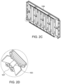
- FIGS. 2 c and 2 d illustrates a bottom perspective view of the formwork panel and a view of a corner element, according to one embodiment of the present invention.
- FIG. 2 e illustrate a top perspective view of the formwork panel according to one embodiment of the present invention.
- FIGS. 3 a , 3 b , 3 c and 3 d illustrates a side view, a top perspective view of a drophead, a fly plate and a plurality of pins and a wedge respectively, according to one embodiment of the present invention.
- FIG. 1 illustrates a top perspective of an erected slab formwork, according to one embodiment of the present invention.
- the formwork comprises a formwork panel 101 , a drophead 102 , and a prop 108 .
- the formwork panel 101 comprises a plurality of slotted windows 103 , a base frame 104 , and a form-lining 105 as shown in FIG. 2 a - 2 e .
- the base frame 104 comprises a corner element 106 on each corner.
- the base frame 104 has a chamfered corner with the slotted window 103 and a bottom rim 107 .
- the bottom rim 107 together with the drophead 102 and the fly plate pin 308 (shown in FIG.
- the drophead 102 is hooked to a slotted window 103 of each corner element 106 .
- the corner element 106 facilitates locking of at least two formwork panels 101 with the drophead 102 through the corner element 106 .
- the drophead 102 is connected to each corner of the formwork panel 101 through the corner element 106 .
- the drophead 102 comprises a top plate 301 , a fly plate 302 , a fly plate pin 308 , a wedge 303 , a stem 304 , a bottom plate 305 , a hole provision 306 for locking mechanism to the prop and a locking bolt 307 .
- a base plate of the prop 108 is connected to the bottom plate 305 through the locking bolt 307 .
- the stem 304 is fixed at a central axis of the bottom plate 305 and further connected vertically to the wedge and the top plate 301 respectively.
- the base frame 104 is chamfered at 45° leading to a connection with a top plate 301 of the drophead 102 .
- the corner element 106 slides into a fly plate 302 of the drophead creating a locking action.
- the wedge 303 comprises a side guiding 309 and an inner sloping level 310 .
- the fly plate 302 is interlocked with the wedge 303 through the side guiding 309 .
- the fly pate 302 comprises a fly plate pin 308 to lock the fly plate in position by tightening of the wedge.
- the wedge has dual action i.e. if hammered in an opposite direction, the wedge releases the locking of the corner element from the fly plate pin followed by the gravity based dropping of panel and fly plate along with the wedge.
- a shuttering method of the slab formwork comprises the steps of:
- a de-shuttering method of the slab formwork comprises the steps of:
- the props remain in place during the formwork stripping process thereby ensures faster slab cycle.
- the props having ground clearance of up to 5 m is possible using PERI props while the present prop is also compatible with various locally developed props if designed as per the PERI loading charts.
- the present slab formwork allows a rapid shuttering and de-shuttering process using a less quantity of labour.
- the chamfered corner of the formwork panel and the corner element allows self-centering and locking of the formwork panel into the dropheads without requirement of hammering, thus reducing a labour cost and complexity in assembly.
- the flyplate and wedge of the drophead provides locking of the corner element in position during the shuttering process and also, the dual action wedge ensures the release of corner element providing a safe deshuttering process ensuring detachment of panel during gravity drop of the fly-plate.
- the slab formwork facilitates re-usability for upto 500 times due to rigid metallic base frame and minimum requirement of infills leading to less rupturing of the formwork panels.
Landscapes
- Engineering & Computer Science (AREA)
- Architecture (AREA)
- Mechanical Engineering (AREA)
- Civil Engineering (AREA)
- Structural Engineering (AREA)
- Forms Removed On Construction Sites Or Auxiliary Members Thereof (AREA)
Abstract
Description
-
- a) Install first 3 props in length and width direction of the formwork panel and connect the bracing frames for lateral stability. The installation of the first 3 props creates the first bay. The props are preformed structure providing a vertical support to the erected formwork panel through dropheads.
- b) Hang the first formwork panel on two sides of the installed props.
- c) Use an erection aid and lift the panel, place it on the 3rd prop and keep it supported with the erection aid until the 4th prop is installed in the bay.
- d) Continue and complete the next bay in similar sequence as provided in Steps a-c. The formwork panels can be erection in both length and width direction.
- e) Fix the braces at regular intervals for providing lateral stability.
- f) Once all the bays are completed, ensure that the infills are filled using a plurality of filler beams and a shuttering plywood.
- g) Ensure that all the props are levelled once all the bays are completed and checked before reinforcement & concreting activities.
-
- a) Hammer the dropheads connected to the formwork panel. The wedge action of drophead ensures a panel-drop of 13 cm from the concreted surface.
- b) Slowly lift up, tilt the first formwork panel and then lower the formwork panel. At least two persons are required for the de-shuttering process.
- c) Slowly remove the subsequent panels in as explained in Steps (a) and (b).
- d) Ensure that no prop is disturbed and is intact with the concreted surface during the de-shuttering.
Claims (7)
Applications Claiming Priority (2)
| Application Number | Priority Date | Filing Date | Title |
|---|---|---|---|
| IN201841045177 | 2018-11-29 | ||
| IN201841045177 | 2018-11-29 |
Publications (2)
| Publication Number | Publication Date |
|---|---|
| US20200173183A1 US20200173183A1 (en) | 2020-06-04 |
| US12065844B2 true US12065844B2 (en) | 2024-08-20 |
Family
ID=68581755
Family Applications (1)
| Application Number | Title | Priority Date | Filing Date |
|---|---|---|---|
| US16/699,531 Active US12065844B2 (en) | 2018-11-29 | 2019-11-29 | Large area slab panel formwork system |
Country Status (7)
| Country | Link |
|---|---|
| US (1) | US12065844B2 (en) |
| EP (1) | EP3887617B1 (en) |
| CN (1) | CN113015833B (en) |
| MA (1) | MA54272B1 (en) |
| PT (1) | PT3887617T (en) |
| WO (1) | WO2020108935A1 (en) |
| ZA (1) | ZA201907705B (en) |
Families Citing this family (6)
| Publication number | Priority date | Publication date | Assignee | Title |
|---|---|---|---|---|
| EP3438365A1 (en) * | 2017-08-02 | 2019-02-06 | DOKA GmbH | Ceiling formwork and method for producing a ceiling element |
| DE102020200318A1 (en) * | 2020-01-13 | 2021-07-15 | Peri Gmbh | Connection of a ceiling formwork to a scaffolding |
| CA3202162A1 (en) * | 2020-12-17 | 2022-06-23 | Giacomo DALLA FONTANA | Supporting head for providing formwork units for floor slabs, and beam and panel for use with the supporting head |
| KR20240042008A (en) * | 2021-08-03 | 2024-04-01 | 페리 에스이 | Lattice beam system for slab formwork |
| CA3198522A1 (en) * | 2022-05-02 | 2023-11-02 | Titan Formwork Systems, Llc | Wedge for a shoring system and related methods |
| CN115233562A (en) * | 2022-08-22 | 2022-10-25 | 中国十九冶集团有限公司 | Formwork support system and construction method for covering beam pouring in highway bridge engineering |
Citations (37)
| Publication number | Priority date | Publication date | Assignee | Title |
|---|---|---|---|---|
| FR680981A (en) * | 1929-04-01 | 1930-05-08 | Apparatus for pouring concrete floors | |
| US1907877A (en) * | 1929-04-01 | 1933-05-09 | Henry W Roos | Apparatus for laying concrete floors |
| GB1191578A (en) * | 1968-06-19 | 1970-05-13 | Scaffolding Great Britain Ltd | Prop Attachment or Head for Supporting Shuttering Elements in the Construction of Floors, Ceilings and Roofs. |
| US3771756A (en) * | 1970-01-15 | 1973-11-13 | Symons Corp | Dome-supporting shore assembly for a concrete ceiling slab form |
| US3784151A (en) * | 1971-04-28 | 1974-01-08 | Kwikform Ltd | Formwork for use in supporting shuttering |
| US4147321A (en) * | 1976-10-07 | 1979-04-03 | C. Evans & Sons Limited | Drop-head support assembly |
| DE3147081A1 (en) * | 1981-05-30 | 1982-12-30 | Udo 4836 Herzebrock Rose | Supporting framework for concrete shutterings |
| GB2107776A (en) * | 1981-09-23 | 1983-05-05 | Rapid Metal Developments Ltd | Formwork support device for use in a construction system |
| EP0380149A1 (en) * | 1989-01-27 | 1990-08-01 | Matab B.V. | Floor shuttering system for erecting the formwork of a concrete floor |
| DE3921064A1 (en) * | 1989-06-28 | 1991-01-10 | Udo Rose | Supporting beam for concrete shuttering - has end plates with flanges joined to sidewalls forming U=shaped connectors |
| DE29705696U1 (en) | 1997-02-11 | 1997-05-22 | Meffert, Burkhard, 57641 Oberlahr | Device for simplifying the formwork of ceiling surfaces in building and civil engineering |
| DE19629321A1 (en) * | 1996-07-20 | 1998-01-22 | Thyssen Huennebeck Gmbh | Shuttering used for floor in building |
| WO2002084050A1 (en) * | 2001-04-03 | 2002-10-24 | Ulma C Y E, S. Coop. | Slab formwork system |
| US20040075042A1 (en) * | 2001-04-03 | 2004-04-22 | Alberto Arozena Bergaretxe | Floor and roof formwork system |
| DE102004004883A1 (en) * | 2003-08-04 | 2005-03-10 | Ischebeck Friedrich Gmbh | Covering panel for a system covering shell comprises support devices held in a position-adjusting manner on a frame so that the outer longitudinal distance can be varied between the support devices |
| WO2006100694A1 (en) * | 2005-03-21 | 2006-09-28 | Faresin Building Division S.P.A. | Falling head support device for supporting beams of formworks for floors |
| CA2698537A1 (en) * | 2006-09-06 | 2008-03-13 | Vittorio Spera | Modular shoring assembly with length adjustable support |
| CN101591973A (en) * | 2009-06-25 | 2009-12-02 | 李斌 | A kind of floor that is used for contains the early-dismantling formwork system that beam, plate and rod structure are built |
| CN201416268Y (en) | 2009-06-25 | 2010-03-03 | 李斌 | Early-dismantling template system for building provided with floor slab with beam, plate and column structure |
| DE102010001042A1 (en) * | 2010-01-20 | 2011-07-21 | Doka Industrie Gmbh | Drop head for a slab formwork system and slab formwork system |
| FR2957957A1 (en) * | 2010-03-26 | 2011-09-30 | Deko | Frame support for casing structure of concrete slabs in building construction site, has four spacers maintaining four frames, where frames are placed on frame support in separate manner, and projections engaged in angle part of one frame |
| US20120042600A1 (en) * | 2010-08-23 | 2012-02-23 | Bacon David L | Shoring post with supplemental beam support |
| EP2570568A2 (en) | 2011-09-16 | 2013-03-20 | DOKA Industrie GmbH | Drop head for a ceiling formwork system and method for removing ceiling formwork elements |
| EP2749713A1 (en) * | 2012-12-28 | 2014-07-02 | Faresin Building Division S.p.A. | Formwork structure for the execution of horizontal castings for the provision of floor slabs |
| CA2803424A1 (en) * | 2013-01-24 | 2014-07-24 | Faresin Building Division S.P.A. | Apparatus for performing horizontal castings to provide floor slabs |
| EP2759658A1 (en) * | 2013-01-24 | 2014-07-30 | Faresin Building Division S.p.A. | Apparatus for performing horizontal castings to provide floor slabs |
| WO2014124695A1 (en) * | 2013-02-18 | 2014-08-21 | Doka Industrie Gmbh | Stripping head and formwork system |
| US20140263941A1 (en) * | 2012-03-19 | 2014-09-18 | Jianhua Zhang | Early-removal formwork system for concreting of constructions comprising beams, plates and columns |
| CN204126259U (en) * | 2014-08-04 | 2015-01-28 | 广东信海建筑有限公司 | A kind of novel morning tears adjustable supporting footstock open |
| US20160060882A1 (en) * | 2014-09-02 | 2016-03-03 | Concrete Support Systems of Houston, LLC | Construction Prop Assembly |
| CN106337559A (en) | 2016-10-13 | 2017-01-18 | 中国建筑股份有限公司 | Early dismantling support system of mold plate support frame and application method of early dismantling support system |
| WO2017093233A1 (en) * | 2015-11-30 | 2017-06-08 | Peri Gmbh | Support head, ceiling support having such a support head, and ceiling boarding having such a ceiling support |
| CA3037043A1 (en) * | 2016-09-19 | 2018-03-22 | Michael L. LENKIN | Adjustable support device and shoring system |
| CN108385969A (en) * | 2018-04-09 | 2018-08-10 | 北京依德伟力建筑模板有限公司 | Early dismantling head and early stripping formwork system support system |
| US10053875B1 (en) * | 2017-07-10 | 2018-08-21 | Doka Gmbh | Formwork support system and formwork support prop |
| US20190010717A1 (en) * | 2017-07-10 | 2019-01-10 | Doka Gmbh | Formwork support system and method of installing a formwork support system |
| CA2988166A1 (en) * | 2017-09-06 | 2019-03-06 | Faresin Building S.P.A. | Support device for supporting beams of formwork for floor slabs |
Family Cites Families (2)
| Publication number | Priority date | Publication date | Assignee | Title |
|---|---|---|---|---|
| KR101073513B1 (en) * | 2009-09-22 | 2011-10-17 | 금강공업 주식회사 | Slab panel and system for constructing the panel and method for assembling and disassembling the panel |
| CN204920199U (en) * | 2015-06-23 | 2015-12-30 | 宋英飞 | A early tear formwork support system open for building building |
-
2019
- 2019-11-06 WO PCT/EP2019/080360 patent/WO2020108935A1/en not_active Ceased
- 2019-11-06 CN CN201980075028.2A patent/CN113015833B/en active Active
- 2019-11-06 EP EP19804650.0A patent/EP3887617B1/en active Active
- 2019-11-06 PT PT198046500T patent/PT3887617T/en unknown
- 2019-11-06 MA MA54272A patent/MA54272B1/en unknown
- 2019-11-21 ZA ZA2019/07705A patent/ZA201907705B/en unknown
- 2019-11-29 US US16/699,531 patent/US12065844B2/en active Active
Patent Citations (42)
| Publication number | Priority date | Publication date | Assignee | Title |
|---|---|---|---|---|
| US1907877A (en) * | 1929-04-01 | 1933-05-09 | Henry W Roos | Apparatus for laying concrete floors |
| FR680981A (en) * | 1929-04-01 | 1930-05-08 | Apparatus for pouring concrete floors | |
| GB1191578A (en) * | 1968-06-19 | 1970-05-13 | Scaffolding Great Britain Ltd | Prop Attachment or Head for Supporting Shuttering Elements in the Construction of Floors, Ceilings and Roofs. |
| US3771756A (en) * | 1970-01-15 | 1973-11-13 | Symons Corp | Dome-supporting shore assembly for a concrete ceiling slab form |
| US3784151A (en) * | 1971-04-28 | 1974-01-08 | Kwikform Ltd | Formwork for use in supporting shuttering |
| US4147321A (en) * | 1976-10-07 | 1979-04-03 | C. Evans & Sons Limited | Drop-head support assembly |
| DE3147081A1 (en) * | 1981-05-30 | 1982-12-30 | Udo 4836 Herzebrock Rose | Supporting framework for concrete shutterings |
| GB2107776A (en) * | 1981-09-23 | 1983-05-05 | Rapid Metal Developments Ltd | Formwork support device for use in a construction system |
| EP0380149A1 (en) * | 1989-01-27 | 1990-08-01 | Matab B.V. | Floor shuttering system for erecting the formwork of a concrete floor |
| DE3921064A1 (en) * | 1989-06-28 | 1991-01-10 | Udo Rose | Supporting beam for concrete shuttering - has end plates with flanges joined to sidewalls forming U=shaped connectors |
| DE19629321A1 (en) * | 1996-07-20 | 1998-01-22 | Thyssen Huennebeck Gmbh | Shuttering used for floor in building |
| DE29705696U1 (en) | 1997-02-11 | 1997-05-22 | Meffert, Burkhard, 57641 Oberlahr | Device for simplifying the formwork of ceiling surfaces in building and civil engineering |
| WO2002084050A1 (en) * | 2001-04-03 | 2002-10-24 | Ulma C Y E, S. Coop. | Slab formwork system |
| US20040075042A1 (en) * | 2001-04-03 | 2004-04-22 | Alberto Arozena Bergaretxe | Floor and roof formwork system |
| US7640871B2 (en) * | 2001-04-03 | 2010-01-05 | Ulma Cye., S. Coop. | Slab formwork system |
| DE102004004883A1 (en) * | 2003-08-04 | 2005-03-10 | Ischebeck Friedrich Gmbh | Covering panel for a system covering shell comprises support devices held in a position-adjusting manner on a frame so that the outer longitudinal distance can be varied between the support devices |
| WO2006100694A1 (en) * | 2005-03-21 | 2006-09-28 | Faresin Building Division S.P.A. | Falling head support device for supporting beams of formworks for floors |
| CA2698537A1 (en) * | 2006-09-06 | 2008-03-13 | Vittorio Spera | Modular shoring assembly with length adjustable support |
| CN101591973A (en) * | 2009-06-25 | 2009-12-02 | 李斌 | A kind of floor that is used for contains the early-dismantling formwork system that beam, plate and rod structure are built |
| CN201416268Y (en) | 2009-06-25 | 2010-03-03 | 李斌 | Early-dismantling template system for building provided with floor slab with beam, plate and column structure |
| DE102010001042A1 (en) * | 2010-01-20 | 2011-07-21 | Doka Industrie Gmbh | Drop head for a slab formwork system and slab formwork system |
| WO2011089148A1 (en) * | 2010-01-20 | 2011-07-28 | Doka Industrie Gmbh | Drophead for a ceiling formwork system and ceiling formwork system |
| FR2957957A1 (en) * | 2010-03-26 | 2011-09-30 | Deko | Frame support for casing structure of concrete slabs in building construction site, has four spacers maintaining four frames, where frames are placed on frame support in separate manner, and projections engaged in angle part of one frame |
| US20120042600A1 (en) * | 2010-08-23 | 2012-02-23 | Bacon David L | Shoring post with supplemental beam support |
| EP2570568A2 (en) | 2011-09-16 | 2013-03-20 | DOKA Industrie GmbH | Drop head for a ceiling formwork system and method for removing ceiling formwork elements |
| US20140263941A1 (en) * | 2012-03-19 | 2014-09-18 | Jianhua Zhang | Early-removal formwork system for concreting of constructions comprising beams, plates and columns |
| US9004443B2 (en) * | 2012-03-19 | 2015-04-14 | Shandong Prima Formwork Co., Ltd. | Early-stripping formwork system for concreting of constructions comprising beams, slab and columns |
| EP2749713A1 (en) * | 2012-12-28 | 2014-07-02 | Faresin Building Division S.p.A. | Formwork structure for the execution of horizontal castings for the provision of floor slabs |
| CA2803424A1 (en) * | 2013-01-24 | 2014-07-24 | Faresin Building Division S.P.A. | Apparatus for performing horizontal castings to provide floor slabs |
| EP2759658A1 (en) * | 2013-01-24 | 2014-07-30 | Faresin Building Division S.p.A. | Apparatus for performing horizontal castings to provide floor slabs |
| WO2014124695A1 (en) * | 2013-02-18 | 2014-08-21 | Doka Industrie Gmbh | Stripping head and formwork system |
| CN204126259U (en) * | 2014-08-04 | 2015-01-28 | 广东信海建筑有限公司 | A kind of novel morning tears adjustable supporting footstock open |
| US20160060882A1 (en) * | 2014-09-02 | 2016-03-03 | Concrete Support Systems of Houston, LLC | Construction Prop Assembly |
| WO2017093233A1 (en) * | 2015-11-30 | 2017-06-08 | Peri Gmbh | Support head, ceiling support having such a support head, and ceiling boarding having such a ceiling support |
| CA3037043A1 (en) * | 2016-09-19 | 2018-03-22 | Michael L. LENKIN | Adjustable support device and shoring system |
| US10053877B2 (en) * | 2016-09-19 | 2018-08-21 | Michael L. Lenkin | Adjustable support device and shoring system |
| US20180334818A1 (en) * | 2016-09-19 | 2018-11-22 | Michael L. Lenkin | Adjustable support device and shoring system |
| CN106337559A (en) | 2016-10-13 | 2017-01-18 | 中国建筑股份有限公司 | Early dismantling support system of mold plate support frame and application method of early dismantling support system |
| US10053875B1 (en) * | 2017-07-10 | 2018-08-21 | Doka Gmbh | Formwork support system and formwork support prop |
| US20190010717A1 (en) * | 2017-07-10 | 2019-01-10 | Doka Gmbh | Formwork support system and method of installing a formwork support system |
| CA2988166A1 (en) * | 2017-09-06 | 2019-03-06 | Faresin Building S.P.A. | Support device for supporting beams of formwork for floor slabs |
| CN108385969A (en) * | 2018-04-09 | 2018-08-10 | 北京依德伟力建筑模板有限公司 | Early dismantling head and early stripping formwork system support system |
Non-Patent Citations (3)
| Title |
|---|
| "Elememt-Deckenschalung Dokadek 30", Sep. 1, 2012 (Sep. 1, 2012), pp. 1-16, XP055078191, Malsach (DE), Retrieved from the Internet: URL:http://www.doka.com/web/media/files/Dokadek_30_Sales_Handout_DE.pdf, retrieved on Sep. 9, 2013. |
| Translation of CN 101591973 A. (Year: 2009). * |
| Translation of CN 108385969 A. (Year: 2018). * |
Also Published As
| Publication number | Publication date |
|---|---|
| ZA201907705B (en) | 2020-12-23 |
| MA54272B1 (en) | 2026-01-30 |
| EP3887617B1 (en) | 2025-10-29 |
| CN113015833A (en) | 2021-06-22 |
| EP3887617A1 (en) | 2021-10-06 |
| US20200173183A1 (en) | 2020-06-04 |
| WO2020108935A1 (en) | 2020-06-04 |
| PT3887617T (en) | 2026-01-28 |
| CN113015833B (en) | 2023-09-22 |
| MA54272A (en) | 2022-03-09 |
Similar Documents
| Publication | Publication Date | Title |
|---|---|---|
| US12065844B2 (en) | Large area slab panel formwork system | |
| US7681366B2 (en) | Curtain wall anchor system | |
| US7921616B2 (en) | Method and apparatus for setting support columns within a foundation | |
| US11898342B2 (en) | Stair installation bracket | |
| US5906076A (en) | Removable support for concrete slab construction and method | |
| US20190071885A1 (en) | Support device for supporting beams of formwork for floor slabs | |
| US4584813A (en) | Method for installing a hanger for a structural member | |
| EP3443171B1 (en) | Construction assembly | |
| GB2243863A (en) | Formwork | |
| US20070266659A1 (en) | Perimeter foundation panel, and method of use | |
| US2859503A (en) | Concrete form tie-tensioning means | |
| US20100005736A1 (en) | Method of concrete building construction and adjustable brace system therefor | |
| US20100037538A1 (en) | Temporary adjustable support brace | |
| US1963983A (en) | Method of building floor and roof structures | |
| US11105104B2 (en) | Formwork apparatus and method for producing vertical wall sections that include connection reinforcement elements for a floor | |
| RU2803440C2 (en) | Large area floor slab panel formworking system | |
| JP3180246B2 (en) | Construction method and construction member for reinforced concrete structure | |
| EP3828364A1 (en) | Assembly kit and method for assembling a safety railing, as well as such a safety railing | |
| KR20240042008A (en) | Lattice beam system for slab formwork | |
| KR101636407B1 (en) | Embeded bracket assembly for lintel brick and construction method thereof | |
| KR102600523B1 (en) | combined wall support device and combined wall construction method using the butt wall support device | |
| JP7599712B2 (en) | Method for constructing slab foundation and partition panel used therefor | |
| KR102905007B1 (en) | Thickness adjustable formwork panel set and method of constructing an opening in the wall using it | |
| KR102827166B1 (en) | Form system for wall expansion | |
| GB2056538A (en) | Shuttering system |
Legal Events
| Date | Code | Title | Description |
|---|---|---|---|
| FEPP | Fee payment procedure |
Free format text: ENTITY STATUS SET TO UNDISCOUNTED (ORIGINAL EVENT CODE: BIG.); ENTITY STATUS OF PATENT OWNER: LARGE ENTITY |
|
| STPP | Information on status: patent application and granting procedure in general |
Free format text: RESPONSE TO NON-FINAL OFFICE ACTION ENTERED AND FORWARDED TO EXAMINER |
|
| STPP | Information on status: patent application and granting procedure in general |
Free format text: FINAL REJECTION MAILED |
|
| STCV | Information on status: appeal procedure |
Free format text: NOTICE OF APPEAL FILED |
|
| STPP | Information on status: patent application and granting procedure in general |
Free format text: DOCKETED NEW CASE - READY FOR EXAMINATION |
|
| STPP | Information on status: patent application and granting procedure in general |
Free format text: NON FINAL ACTION MAILED |
|
| STPP | Information on status: patent application and granting procedure in general |
Free format text: NON FINAL ACTION MAILED |
|
| STPP | Information on status: patent application and granting procedure in general |
Free format text: FINAL REJECTION MAILED |
|
| STPP | Information on status: patent application and granting procedure in general |
Free format text: DOCKETED NEW CASE - READY FOR EXAMINATION |
|
| STPP | Information on status: patent application and granting procedure in general |
Free format text: NON FINAL ACTION MAILED |
|
| STPP | Information on status: patent application and granting procedure in general |
Free format text: RESPONSE TO NON-FINAL OFFICE ACTION ENTERED AND FORWARDED TO EXAMINER |
|
| STPP | Information on status: patent application and granting procedure in general |
Free format text: NOTICE OF ALLOWANCE MAILED -- APPLICATION RECEIVED IN OFFICE OF PUBLICATIONS |
|
| ZAAA | Notice of allowance and fees due |
Free format text: ORIGINAL CODE: NOA |
|
| ZAAB | Notice of allowance mailed |
Free format text: ORIGINAL CODE: MN/=. |
|
| STPP | Information on status: patent application and granting procedure in general |
Free format text: NOTICE OF ALLOWANCE MAILED -- APPLICATION RECEIVED IN OFFICE OF PUBLICATIONS |
|
| AS | Assignment |
Owner name: PERI SE, GERMANY Free format text: CHANGE OF NAME;ASSIGNOR:PERI AG;REEL/FRAME:068377/0101 Effective date: 20211215 Owner name: PERI AG, GERMANY Free format text: CHANGE OF NAME;ASSIGNOR:PERI GMBH;REEL/FRAME:068377/0092 Effective date: 20210520 |
|
| STPP | Information on status: patent application and granting procedure in general |
Free format text: PUBLICATIONS -- ISSUE FEE PAYMENT VERIFIED |
|
| STCF | Information on status: patent grant |
Free format text: PATENTED CASE |