US12062893B2 - Cable support brackets - Google Patents
Cable support brackets Download PDFInfo
- Publication number
- US12062893B2 US12062893B2 US17/415,098 US202017415098A US12062893B2 US 12062893 B2 US12062893 B2 US 12062893B2 US 202017415098 A US202017415098 A US 202017415098A US 12062893 B2 US12062893 B2 US 12062893B2
- Authority
- US
- United States
- Prior art keywords
- cable
- base
- bridge
- support bracket
- antenna
- Prior art date
- Legal status (The legal status is an assumption and is not a legal conclusion. Google has not performed a legal analysis and makes no representation as to the accuracy of the status listed.)
- Active, expires
Links
Images


Classifications
-
- H—ELECTRICITY
- H01—ELECTRIC ELEMENTS
- H01Q—ANTENNAS, i.e. RADIO AERIALS
- H01Q1/00—Details of, or arrangements associated with, antennas
- H01Q1/12—Supports; Mounting means
-
- H—ELECTRICITY
- H01—ELECTRIC ELEMENTS
- H01Q—ANTENNAS, i.e. RADIO AERIALS
- H01Q1/00—Details of, or arrangements associated with, antennas
- H01Q1/12—Supports; Mounting means
- H01Q1/22—Supports; Mounting means by structural association with other equipment or articles
- H01Q1/24—Supports; Mounting means by structural association with other equipment or articles with receiving set
- H01Q1/241—Supports; Mounting means by structural association with other equipment or articles with receiving set used in mobile communications, e.g. GSM
- H01Q1/246—Supports; Mounting means by structural association with other equipment or articles with receiving set used in mobile communications, e.g. GSM specially adapted for base stations
-
- H—ELECTRICITY
- H01—ELECTRIC ELEMENTS
- H01R—ELECTRICALLY-CONDUCTIVE CONNECTIONS; STRUCTURAL ASSOCIATIONS OF A PLURALITY OF MUTUALLY-INSULATED ELECTRICAL CONNECTING ELEMENTS; COUPLING DEVICES; CURRENT COLLECTORS
- H01R13/00—Details of coupling devices of the kinds covered by groups H01R12/70 or H01R24/00 - H01R33/00
- H01R13/58—Means for relieving strain on wire connection, e.g. cord grip, for avoiding loosening of connections between wires and terminals within a coupling device terminating a cable
-
- H—ELECTRICITY
- H01—ELECTRIC ELEMENTS
- H01R—ELECTRICALLY-CONDUCTIVE CONNECTIONS; STRUCTURAL ASSOCIATIONS OF A PLURALITY OF MUTUALLY-INSULATED ELECTRICAL CONNECTING ELEMENTS; COUPLING DEVICES; CURRENT COLLECTORS
- H01R24/00—Two-part coupling devices, or either of their cooperating parts, characterised by their overall structure
- H01R24/38—Two-part coupling devices, or either of their cooperating parts, characterised by their overall structure having concentrically or coaxially arranged contacts
- H01R24/40—Two-part coupling devices, or either of their cooperating parts, characterised by their overall structure having concentrically or coaxially arranged contacts specially adapted for high frequency
- H01R24/54—Intermediate parts, e.g. adapters, splitters or elbows
- H01R24/542—Adapters
-
- H—ELECTRICITY
- H02—GENERATION; CONVERSION OR DISTRIBUTION OF ELECTRIC POWER
- H02G—INSTALLATION OF ELECTRIC CABLES OR LINES, OR OF COMBINED OPTICAL AND ELECTRIC CABLES OR LINES
- H02G3/00—Installations of electric cables or lines or protective tubing therefor in or on buildings, equivalent structures or vehicles
- H02G3/02—Details
- H02G3/04—Protective tubing or conduits, e.g. cable ladders or cable troughs
- H02G3/0456—Ladders or other supports
Definitions
- the present invention is directed generally toward telecommunications equipment, and more particularly, support brackets for coaxial cable connections with an antenna.
- New towers will need to be designed to support greater numbers of antenna and radio units, while existing towers are retrofitted to support more units, and effort is made to fully utilize space available on the towers.
- the cables attaching the radio to the antenna typically protrude from the bottom of the antenna for some unsupported length. It is typically desirable to secure these cables to maintain a sense of organization and to prevent swaying in the wind.
- a system of cable support brackets is commonly used to hold these cables in place.
- Those support systems usually also mount to the same mounting structure to which the antenna is mounted (e.g., an individual pole of an antenna mount or a monopole).
- Areas near cellular antennas can be (relatively) high radio frequency (RF) energy environments.
- Conductive items in these areas can generate undesirable passive intermodulation (PIM).
- PIM passive intermodulation
- Typical examples of potential PIM-generating conditions include the combination of steel-on-steel contact (between two or more components), plus low contact pressure and/or relative movement between the steel components at the joint. As such, it may be desirable to provide solutions near an antenna with reduced (or eliminated) likelihood of PIM generation.
- a first aspect of the present invention is directed to a cable support bracket.
- the cable support bracket may comprise a base configured to be mounted to an antenna, the base comprising a plurality of apertures, each aperture configured to receive a cable hanger; a cable guide having a generally arced outer profile, wherein the cable guide is coupled to or integral with the base and extends outwardly from one end of the base; and a plurality of cable hangers, each cable hanger secured in a respective aperture in the base.
- the cable support bracket may comprise a base configured to be mounted to an antenna and configured to receive and secure a first plurality of cable hangers; a bridge removably attached to the base, the bridge configured to receive and secure a second plurality of cable hangers; and a cable guide having a generally arced outer profile, wherein the cable guide is coupled to or integral with the base and extends outwardly from one end of the base.
- the antenna assembly may comprise an antenna; and a cable support bracket, the cable support bracket comprising: a base configured to be mounted to the antenna, the base comprising a plurality of apertures, each aperture configured to receive a cable hanger; a cable guide having a generally arced outer profile, wherein the cable guide is coupled to or integral with the base and extends outwardly from one end of the base; and a plurality of cable hangers, each cable hanger secured in a respective aperture in the base, wherein the cable support bracket is mounted to the antenna.
- the antenna assembly may comprise an antenna; and a cable support bracket, the support bracket comprising: a base configured to be mounted to an antenna, the base comprising a plurality of apertures, each aperture configured to receive a cable hanger; a cable guide having a generally arced outer profile, wherein the cable guide is coupled to or integral with the base and extends outwardly from one end of the base; and a plurality of cable hangers, each cable hanger secured in a respective aperture in the base, wherein the cable support bracket is mounted to the antenna, and wherein at least one of the plurality of cables is secured within at least one of the plurality of cable hangers.
- the method may comprise providing a cable support bracket, the support bracket comprising: a base configured to be mounted to an antenna, the base comprising a plurality of apertures, each aperture configured to receive a cable hanger; a cable guide having a generally arced outer surface, wherein the cable guide is coupled to or integral with the base and extends outwardly from one end of the base; and a plurality of cable hangers, each cable hanger secured in a respective aperture in the base; mounting the cable support bracket to an antenna having a plurality of connection ports such that each cable hanger aligns with a respective connection port; connecting a plurality of coaxial cables to the plurality of connection ports, wherein each coaxial cable is connected to a respective connection port; and securing each coaxial cable to a respective cable hanger.
- the method may comprise providing a cable support bracket, the support bracket comprising: a base configured to be mounted to an antenna and configured to receive and secure a first plurality of cable hangers; a bridge removably attached to the base, the bridge configured to receive and secure a second plurality of cable hangers; and a cable guide having a generally arced outer profile, wherein the cable guide is coupled to or integral with the base and extends outwardly from one end of the base; mounting the cable support bracket to an antenna having a plurality of connection ports such that each cable hanger aligns with a respective connection port; connecting a plurality of coaxial cables to the plurality of connection ports, wherein each coaxial cable is connected to a respective connection port; and securing each coaxial cable to a respective cable hanger.
- FIG. 1 is a side perspective view of a cable support bracket according to embodiments of the present invention.
- FIG. 2 is a side perspective exploded view of the cable support bracket of FIG. 1 .
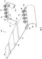
- FIG. 3 is a front perspective view of a cable support bracket according to alternative embodiments of the present invention.
- FIG. 4 is a side perspective view of the cable support bracket of FIG. 1 attached to an antenna to form an antenna assembly.
- FIG. 5 is a rear perspective view of the antenna assembly of FIG. 4 .
- FIG. 6 is a bottom view of the antenna assembly of FIG. 4 .
- FIG. 7 is a front view of the antenna assembly of FIG. 4 .
- FIG. 8 is a rear view of the antenna assembly of FIG. 4 .
- FIG. 9 is a side view of the cable support bracket of FIG. 1 .
- FIG. 10 is a side perspective view of the antenna assembly utilizing the cable support bracket of FIG. 3 in combination with coaxial cables according to embodiments of the present invention.
- FIG. 11 is a side perspective view of the antenna assembly and cables of FIG. 10 .
- FIG. 12 is a bottom view of the antenna assembly and cables of FIG. 10 .
- FIG. 13 is a side perspective view of a cable support bracket according to alternative embodiments of the present invention.
- first, second, etc. may be used herein to describe various elements, components, regions, layers and/or sections, these elements, components, regions, layers and/or sections should not be limited by these terms. These terms are only used to distinguish one element, component, region, layer or section from another region, layer or section. Thus, a first element, component, region, layer or section discussed below could be termed a second element, component, region, layer or section without departing from the teachings of the present invention.
- the sequence of operations (or steps) is not limited to the order presented in the claims or figures unless specifically indicated otherwise.
- phrases such as “between X and Y” and “between about X and Y” should be interpreted to include X and Y.
- phrases such as “between about X and Y” mean “between about X and about Y.”
- phrases such as “from about X to Y” mean “from about X to about Y.”
- Embodiments of the present invention are directed to cable support brackets and assemblies which may greatly reduce passive intermodulation (PIM) and provide for easy identification of coaxial cables connected to an antenna.
- a cable support bracket of the present invention may provide optimized and predetermined coaxial support locations for coaxial cable connections at a base station antenna.
- a cable support bracket of the present invention may mitigate PIM caused by bends in a coaxial cable that are that are too close to the connector body.
- a cable support bracket of the present invention may provide an integrated cable bend radius guide that helps maintain the minimum bend radius requirements of a coaxial cable.
- a cable support bracket of the present invention may be fabricated from a non-conductive polymer-based material which may help to mitigate PIM.
- a cable support bracket of the present invention may provide for easy identification of organized coaxial cables attached to an antenna.
- a cable support bracket of the present invention may be integrated into an existing antenna structure or as a separate accessory.
- a cable support bracket of the present invention may be integrated for use with polymer-based cable hangers.
- a cable support bracket of the present invention may be slotted or provided with holes to help reduce exposure to wind drag.
- the cable support bracket 100 of the present invention may comprise a base 102 and a cable guide 106 .
- the base 102 of the cable support bracket 100 may be configured to receive and secure a plurality of cable hangers 114 .
- the cable support bracket 100 may further comprise a bridge 112 .
- the cable support bracket 100 of the present invention comprises a base 102 .
- the base 102 is configured to be mounted to an antenna 150 (see, e.g., FIG. 5 ).
- the base 102 may comprise a mounting plate 104 to assist in mounting the cable support bracket 100 to the antenna 150 .
- the mounting plate 104 may be coupled to or integral with the base 102 .
- the base 102 (and/or mounting plate 104 ) may be configured such that it can be secured to a pre-existing mounting bracket 154 on an antenna 150 (see, e.g., FIG. 5 ).
- the antenna 150 is a base station antenna. Other methods may be employed to secure or provide additional support to a bracket 100 being mounted to an antenna 150 , such as, for example, elastomeric bands, adhesives, or the like.
- the cable support bracket 100 is formed of a non-metallic and/or polymeric material.
- the cable support bracket 100 comprises acetal, nylon, polypropylene, polyvinyl chloride, and/or fiberglass.
- the base 102 of the cable support bracket 100 may comprise one or more ridges 116 .
- the ridge(s) 116 may provide additional structural support and/or stiffness to the cable support bracket 100 when the bracket 100 is mounted to an antenna 150 .
- the cable support bracket 100 further comprises a plurality of cable hangers 114 .
- the cable support bracket 100 may comprise 1, 2, 3, 4 or more cable hangers 114 .
- typically the number of cable hangers 114 is equal to the number of connection ports 152 at the bottom 150 b of an antenna 150 .
- the cable support bracket 100 may comprise ten (10) cable hangers 114 .
- Each cable hanger 114 is configured to hold and secure a respective coaxial cable 250 when the cable 250 is connected to an antenna 150 (see, e.g., FIGS. 10 - 12 ).
- the cable hangers 114 may be attached to the base 102 of the cable support bracket 100 .
- the base 102 may comprise a plurality of apertures 107 .
- Each aperture 107 may be configured to receive and secure a respective cable hanger 114 to the base 102 (see, e.g., FIG. 5 ).
- the apertures 107 have a diameter in the range of 0.5 inches to 1 inch.
- the apertures 107 have a nominal diameter of 0.75 inches.
- the cable hangers 114 have a height (H ch ) in a range of about 0.5 inches to about 1.5 inches (see, e.g., FIG. 9 ).
- H ch height
- Exemplary types of cable hangers 114 that may be used with a cable support bracket 100 of the present invention include, but are not limited to, SSH-114-1 and SSH-1014-1 available from CommScope, Inc. (Joliet, Illinois). See also, e.g., United States Patent Application Publication No. 2018/0045336 to Vaccaro, which is incorporated herein by reference in its entirety.
- the base 102 of the cable support bracket 100 may comprise a plurality of base support platforms 108 .
- Each base support platform 108 may be configured to receive and secure a cable hanger 114 .
- each aperture 107 may configured to receive and secure a respective base support platform 108 to the base 102 .
- the base support platforms 108 may be attached to the base 102 of the cable support bracket 100 via the apertures 107 and each cable hanger 114 is attached to a respective base support platform 108 .
- Exemplary types of base support platforms 108 that may be used with a cable support bracket 100 of the present invention include, but are not limited to, SA-1C-1F and SA-1TR available from CommScope, Inc.
- the base support platforms 108 assist with aligning each of the cable hangers 114 with a respective connection port 152 located at the bottom 150 b of an antenna 150 (see, e.g., FIG. 6 ).
- the plurality of base support platforms 108 are formed of a non-metallic and/or polymeric material, such as, for example, nylon, acetal, polypropylene, or polyethylene.
- each base standoff platform 108 has a height (H b1 ) in a range of about 0.5 inches to about 1.5 inches. The height (H b1 ) of the base standoff platform 108 has the potential of being increased depending on the antenna type and connector locations on the antenna.
- the cable support bracket 100 further comprises a cable guide 106 .
- the cable guide (or cable bend radius guide) 106 may be coupled to or integral with the base 102 of the bracket 100 and extends outwardly from one end of the base 102 .
- the base 102 and the cable guide 106 may be a unitary member.
- the cable guide 106 may have a generally arced outer profile (see also, e.g., FIG. 9 ).
- the cable guide 106 has a radius (R) of about 2 inches or greater, and may extend over an arc distance of at least 90 degrees, and in some cases, at least 120 degrees.
- Coaxial cables 250 have minimum bend radius requirements.
- Bends in a coaxial cable 250 may damage the cable and/or cause unwanted passive intermodulation (PIM).
- the cable guide 106 of the present invention helps to maintain the minimum bend radius requirements of a coaxial cable 250 when the cable 250 is connected to an antenna 150 , thereby helping to reduce unwanted PIM near the antenna 150 (see, e.g., FIGS. 10 - 12 ).
- the cable support bracket 100 of the present invention has a length (L) and a width (W).
- the length (L) and width (W) of the bracket 100 may vary depending on the type of antenna 150 that the bracket 100 is being mounted and/or the number of connection ports 152 at the bottom 150 b of the antenna 150 (see, e.g., FIG. 8 ).
- the cable support bracket 100 has a length (L) in a range of about 20 inches to about 30 inches and a width (W) in a range of about 10 inches to about 36 inches.
- the cable guide 106 may have greater width (W) than the base 102 of the cable support bracket 100 (see, e.g., FIG. 7 and FIG. 8 ).
- the bracket 100 of the present invention may be sized to fit an antenna 150 having two (2) connection ports 152 to an antenna 150 having fifty (50) or more connection ports 152 .
- the cable support bracket 100 may further comprise a bridge 112 .
- the bridge 112 may be removably attached to the base 102 .
- the bridge 112 may comprise one or more latching members 118 .
- the base 102 of the bracket 100 may comprise slots 120 configured to receive the latching members 118 of the bridge 112 . When inserted into the slots 120 , the latching members 118 secure the bridge 112 to the base 102 .
- the bridge 112 may be integral with the base 102 , such that the bridge 112 and the base 102 comprise a unitary member.
- the bridge 112 may comprise a plurality of bridge standoff platforms 110 .
- the bridge standoff platforms 110 may be coupled to or integral with the bridge 112 .
- Each bridge standoff platform 110 has a height (H b2 ) and is configured to receive a cable hanger 114 (see also, e.g., FIG. 9 ).
- a cable hanger 114 is secured in a respective bridge standoff platform 110 .
- each bridge standoff platform 110 has a height (H b2 ) in a range of about 0.5 inches to about 1.5 inches.
- the height (H b2 ) of the bridge standoff platform 110 has the potential of being increased based on antenna connector layouts.
- the bridge 112 may comprise a plurality of apertures 109 configured to receive and secure a respective cable hanger 114 to the bridge 102 (see, e.g., FIG. 3 ).
- each bridge standoff platform 110 may be adjustable to allow the proper alignment of a cable hanger 114 with a connection port 152 of an antenna 150 .
- each bridge standoff platform 110 may comprise threads where turning the platform 110 clockwise or counterclockwise will raise or lower the platform 110 to a desirable height (H b2 ) above the top of the bridge 112 .
- the bridge 112 is attached to the base 102 such that the bridge standoff platforms 110 (and cable hangers 114 attached to the bridge standoff platforms 110 ) reside above the base standoff platforms 108 (and the cable hangers 114 attached to the base standoff platforms 108 ).
- the cable hangers 114 attached to the bridge 112 reside directly above the cable hangers 114 attached to the base 102 .
- the bridge 112 should have a sufficient height (H b ) such that the cable hangers 114 attached to the bridge 112 align with an upper row of connection ports 152 .
- the bridge 112 should also have a sufficient height (H b ) above the cable hangers 114 secured to the base 102 (or in a base standoff platform 108 ) such that the bridge 112 does not contact the cable hangers 114 secured to the base 102 (or base standoff platforms 108 ).
- a sufficient height (H b ) of the bridge 112 also allows for enough space for easy installation and identification of coaxial cables 250 by a technician (see also, e.g., FIG. 12 ).
- the bridge 112 has a height (H b ) relative to the base 102 in the range of about 3 inches to about 6 inches.
- the height (H b ) of the bridge 112 can vary based on antenna design and has the potential to be increased based on the type of antenna.
- the height (H b ) of the bridge 112 may be adjustable.
- each side of the bridge 112 may comprise a telescoping member that allows the bridge 112 to be raised and lowered to a desirable height (H b ).
- one or more cable hangers 114 may be stacked on top of one another to align one or more cable hangers 114 with one or more connection ports 152 .
- three cable hangers 114 may be stacked on top of one another such that the bottom and top cable hangers 114 in the stack each align with a respective connection port 152 .
- the base 102 of the cable support bracket 100 may further comprise slots (or holes) 122 .
- the slots 122 may be included to reduce the exposure area of the cable support bracket 100 , thereby mitigating wind drag on the cable support bracket 100 .
- the slots 122 may vary in number, shape and/or size.
- FIGS. 4 - 8 an antenna assembly 200 according to some embodiments of the present invention is illustrated.
- a cable support bracket 100 as described herein is mounted to an antenna 150 .
- the base 102 of the cable support bracket 100 is secured to the antenna 150 by a mounting plate 104 (see, e.g., FIG. 5 ).
- the mounting plate 104 is configured such that it can be secured to a pre-existing mounting bracket 154 on the antenna 150 .
- the cable support bracket 100 aligns the cable hangers 114 with the connection ports 152 of the antenna 150 . Aligning the cable hangers 114 with the connection ports 152 helps to prevent or reduce bending the coaxial cables 250 when secured within the cable hangers 114 . Thus, the cable support bracket 100 helps to mitigate PIM caused by bends of the coaxial cable that are that are too close to the connector body that terminates the cable. In some embodiments, the cable support bracket 100 may be color-coded to match with the connection ports 152 of an antenna 150 allowing for easy installation and organization of the cables 250 by a technician (see also, e.g., FIGS. 10 - 12 ).
- the cable support bracket 100 has ten cable hangers 114 to match the ten connection ports 152 of the antenna 150 (see, e.g., four cable hangers 114 are attached to the base 102 and six cable hangers 114 are attached to the bridge 112 ). Note that two of the cable hangers 114 are attached to the bottom of the bridge 112 in order to properly align with two of the connection ports 152 on the antenna 150 .
- the arrangement of cable hangers 114 on the base 102 and/or bridge 112 may vary depending on how the connection ports 152 are arranged on an antenna 150 .
- the cable support brackets 100 of the present invention can be modified to match different arrangements of connection ports 152 on different antennas 150 .
- the cable support bracket 100 of the present invention is attached to an antenna 150 such that the cable guide 106 and cable hangers 114 are a sufficient distance (D) from the bottom 150 b (and connection ports 152 ) of the antenna 150 .
- the cable hangers 114 (and cable guide 106 ) are not too far from the bottom 150 b and connection ports 152 of the antenna 150 .
- the farther away the cable hangers 114 are from the connection ports 152 the greater the length of cable 250 extending between the connection ports 152 and cable hangers 114 that is exposed to wind. This could lead to damage to and/or loosening of the connection between the cables 250 and the antenna 150 , and/or can add to the wind load of the antenna assembly 200 .
- the cable hangers 114 and/or cable guide 106 are at distance from the bottom 150 b of an antenna 150 in a range of about 9 inches to about 13 inches.
- FIGS. 10 - 12 illustrated is an antenna assembly 200 , in combination with a plurality of coaxial cables 250 , according to embodiments of the present invention.
- Each of the cables 250 are connected to a respective connection port 152 located at the bottom 150 b of an antenna 150 .
- the cable support bracket 100 of the present invention aligns the cable hangers 114 with the connection ports 152 to provide optimized and predetermined coaxial support for the coaxial cable connections at the antenna 150 .
- the cable support bracket 100 helps keep the coaxial cables 250 straight near the connection ports 152 . Reducing bends in the coaxial cables 250 that are too close to the connector body help to mitigate PIM.
- the cable guide 106 helps to maintain the minimum bend radius requirements of the coaxial cables 250 , thereby also helping to reduce unwanted PIM near the antenna 150 .
- the cable support bracket 100 of the present invention may provide for easy identification of organized coaxial cables 250 attached to the antenna 150 .
- the cable support bracket 300 may comprise a shroud 220 .
- the shroud 220 may be coupled to or integral with the base 102 and have one or more walls 220 w .
- the walls 220 w of the shroud 220 may be configured to receive and secure a plurality of cable hangers 114 .
- the cable support bracket 300 is configured to align the cable hangers 114 with the connection ports 152 of the antenna 150 .
- a plurality of cable hangers 114 may be secured to an interior of one or more walls 220 w of the shroud 220 .
- the cable hangers 114 may be attached to and hang down from the interior of a top wall 220 w of the shroud 220 such that the cable hangers 114 may align with an upper row of connection ports 152 .
- the shroud 220 may be configured to meet or overlap with the lower edge of the antenna 150 to cover cable connections at the bottom 150 b of the antenna 150 .
- the shroud 220 may also have a length such that the shroud covers the length of cable 250 extending between the connection ports 152 at the bottom 150 b of an antenna 150 and the cable hangers 114 , thereby protecting the cables 250 (and cable connection(s) to the antenna 150 ) from harsh environmental conditions (e.g., wind, rain, snow, etc.).
- the shroud 220 may be configured to fit around the radome of an antenna 150 (or in some embodiments may be integral with the radome) and may assist in mounting the cable support bracket 300 to the antenna 150 or may be used as additional support when the bracket 100 is mounted to an antenna 150 .
- a method may comprise providing a cable support bracket, the support bracket comprising: a base configured to be mounted to an antenna, the base comprising a plurality of base standoff platforms, each standoff platform configured to receive a cable hanger; a cable guide having a generally arced outer surface, wherein the cable guide is coupled to or integral with the base and extends outwardly from one end of the base; and a plurality of cable hangers, each cable hanger secured in a respective base standoff platform; mounting the cable support bracket to an antenna having a plurality of connection ports such that each cable hanger aligns with a respective connection port; connecting a plurality of coaxial cables to the plurality of connection ports, wherein each coaxial cable is connected to a respective connection port; and securing each coaxial cable to a respective cable hanger.
- the method may comprise providing a cable support bracket, the support bracket comprising: a base configured to be mounted to an antenna and configured to receive and secure a first plurality of cable hangers; a bridge removably attached to the base, the bridge configured to receive and secure a second plurality of cable hangers; and a cable guide having a generally arced outer profile, wherein the cable guide is coupled to or integral with the base and extends outwardly from one end of the base; mounting the cable support bracket to an antenna having a plurality of connection ports such that each cable hanger aligns with a respective connection port; connecting a plurality of coaxial cables to the plurality of connection ports, wherein each coaxial cable is connected to a respective connection port; and securing each coaxial cable to a respective cable hanger
Landscapes
- Engineering & Computer Science (AREA)
- Computer Networks & Wireless Communication (AREA)
- Architecture (AREA)
- Civil Engineering (AREA)
- Structural Engineering (AREA)
- Support Of Aerials (AREA)
Abstract
Description
Claims (20)
Priority Applications (1)
| Application Number | Priority Date | Filing Date | Title |
|---|---|---|---|
| US17/415,098 US12062893B2 (en) | 2019-01-11 | 2020-01-09 | Cable support brackets |
Applications Claiming Priority (3)
| Application Number | Priority Date | Filing Date | Title |
|---|---|---|---|
| US201962791104P | 2019-01-11 | 2019-01-11 | |
| PCT/US2020/012864 WO2020146584A1 (en) | 2019-01-11 | 2020-01-09 | Cable support brackets |
| US17/415,098 US12062893B2 (en) | 2019-01-11 | 2020-01-09 | Cable support brackets |
Publications (2)
| Publication Number | Publication Date |
|---|---|
| US20220045493A1 US20220045493A1 (en) | 2022-02-10 |
| US12062893B2 true US12062893B2 (en) | 2024-08-13 |
Family
ID=71520625
Family Applications (1)
| Application Number | Title | Priority Date | Filing Date |
|---|---|---|---|
| US17/415,098 Active 2041-06-09 US12062893B2 (en) | 2019-01-11 | 2020-01-09 | Cable support brackets |
Country Status (2)
| Country | Link |
|---|---|
| US (1) | US12062893B2 (en) |
| WO (1) | WO2020146584A1 (en) |
Citations (16)
| Publication number | Priority date | Publication date | Assignee | Title |
|---|---|---|---|---|
| US20030178535A1 (en) * | 2002-03-04 | 2003-09-25 | Roger Jette | Cable tray apparatus and method |
| JP2004073000A (en) | 2002-08-08 | 2004-03-04 | Ortho Clinical Diagnostics Inc | Support device for ribbon cable |
| US20070021095A1 (en) * | 2005-07-22 | 2007-01-25 | Tci International, Inc. | Apparatus and method for local broadcasting in the twenty-six megahertz short wave band |
| KR100772839B1 (en) | 2007-04-13 | 2007-11-02 | 주식회사 엘스콤 | Low Voltage Cable Support for Switchgear |
| US20090231794A1 (en) * | 2008-03-17 | 2009-09-17 | Dell Products L.P. | Removable Display Cover |
| JP2010255760A (en) | 2009-04-24 | 2010-11-11 | Three M Innovative Properties Co | Cable support device |
| US20110075646A1 (en) * | 2003-05-20 | 2011-03-31 | Belair Networks Inc. | Wireless system for communication |
| CN202797276U (en) | 2012-08-27 | 2013-03-13 | 苏州市大富通信技术有限公司 | Antenna device and cable connection structure |
| JP6116518B2 (en) | 2014-04-30 | 2017-04-19 | 富士通フロンテック株式会社 | Cable guide operation restriction device |
| US9841123B1 (en) * | 2015-06-05 | 2017-12-12 | James C. White Company, Inc. | Cable tray system |
| US20190006827A1 (en) * | 2015-05-14 | 2019-01-03 | Sticnstac Llc | Panel wire support brackets |
| US20200119425A1 (en) * | 2018-10-11 | 2020-04-16 | ConcealFab Corporation | Low-PIM Universal Antenna Equipment Mount |
| US20220263304A1 (en) * | 2021-02-15 | 2022-08-18 | ConcealFab Corporation | Low-PIM Multi-Function Mounting System |
| US20220360059A1 (en) * | 2021-05-05 | 2022-11-10 | Shoals Technologies Group, Llc | Solar cable retention clips with resilient hooks for structure mounting |
| US20220359102A1 (en) * | 2021-05-05 | 2022-11-10 | Shoals Technologies Group, Llc | Solar cable retention clips and systems |
| US20230291188A1 (en) * | 2022-03-09 | 2023-09-14 | Eaton Intelligent Power Limited | Cable tray splice plate assembly |
-
2020
- 2020-01-09 US US17/415,098 patent/US12062893B2/en active Active
- 2020-01-09 WO PCT/US2020/012864 patent/WO2020146584A1/en not_active Ceased
Patent Citations (16)
| Publication number | Priority date | Publication date | Assignee | Title |
|---|---|---|---|---|
| US20030178535A1 (en) * | 2002-03-04 | 2003-09-25 | Roger Jette | Cable tray apparatus and method |
| JP2004073000A (en) | 2002-08-08 | 2004-03-04 | Ortho Clinical Diagnostics Inc | Support device for ribbon cable |
| US20110075646A1 (en) * | 2003-05-20 | 2011-03-31 | Belair Networks Inc. | Wireless system for communication |
| US20070021095A1 (en) * | 2005-07-22 | 2007-01-25 | Tci International, Inc. | Apparatus and method for local broadcasting in the twenty-six megahertz short wave band |
| KR100772839B1 (en) | 2007-04-13 | 2007-11-02 | 주식회사 엘스콤 | Low Voltage Cable Support for Switchgear |
| US20090231794A1 (en) * | 2008-03-17 | 2009-09-17 | Dell Products L.P. | Removable Display Cover |
| JP2010255760A (en) | 2009-04-24 | 2010-11-11 | Three M Innovative Properties Co | Cable support device |
| CN202797276U (en) | 2012-08-27 | 2013-03-13 | 苏州市大富通信技术有限公司 | Antenna device and cable connection structure |
| JP6116518B2 (en) | 2014-04-30 | 2017-04-19 | 富士通フロンテック株式会社 | Cable guide operation restriction device |
| US20190006827A1 (en) * | 2015-05-14 | 2019-01-03 | Sticnstac Llc | Panel wire support brackets |
| US9841123B1 (en) * | 2015-06-05 | 2017-12-12 | James C. White Company, Inc. | Cable tray system |
| US20200119425A1 (en) * | 2018-10-11 | 2020-04-16 | ConcealFab Corporation | Low-PIM Universal Antenna Equipment Mount |
| US20220263304A1 (en) * | 2021-02-15 | 2022-08-18 | ConcealFab Corporation | Low-PIM Multi-Function Mounting System |
| US20220360059A1 (en) * | 2021-05-05 | 2022-11-10 | Shoals Technologies Group, Llc | Solar cable retention clips with resilient hooks for structure mounting |
| US20220359102A1 (en) * | 2021-05-05 | 2022-11-10 | Shoals Technologies Group, Llc | Solar cable retention clips and systems |
| US20230291188A1 (en) * | 2022-03-09 | 2023-09-14 | Eaton Intelligent Power Limited | Cable tray splice plate assembly |
Non-Patent Citations (2)
Also Published As
| Publication number | Publication date |
|---|---|
| WO2020146584A1 (en) | 2020-07-16 |
| US20220045493A1 (en) | 2022-02-10 |
Similar Documents
| Publication | Publication Date | Title |
|---|---|---|
| US10415723B2 (en) | Adapter for mounting cable hangers | |
| US12107317B2 (en) | Universal small cell antenna mounts and antenna mount assemblies | |
| US11555559B2 (en) | Adapter for mounting cable hangers | |
| KR101638798B1 (en) | Apparatus for multiple antennas in wireless communication system | |
| EP3793025B1 (en) | Base station antenna | |
| EP2521218A2 (en) | Antenna array arrangement and a multi band antenna | |
| US20180083368A1 (en) | Donor panel antenna | |
| US11888220B2 (en) | Base station antennas having bottom end caps with angled connector ports | |
| US20240213650A1 (en) | Base station antennas having an active antenna module(s) and related mounting systems and methods | |
| US11936095B2 (en) | Telecommunications antenna mounts and associated transition covers | |
| US11362502B2 (en) | Adapter for cable hanger | |
| US20250033925A1 (en) | Devices for cable management | |
| US12463315B2 (en) | Telecommunications equipment mounting pipe for a monopole platform assembly and related platform assemblies | |
| US12062893B2 (en) | Cable support brackets | |
| EP2472670A1 (en) | Antenna device | |
| WO2021080759A1 (en) | Cable management system for base station antennas | |
| US12542376B2 (en) | Radiator assembly | |
| CN120435801A (en) | Antenna and sector frame mounting systems | |
| US20250309517A1 (en) | Sector frame antenna mount assemblies | |
| US20250374467A1 (en) | Mounting assemblies for remote radio units | |
| US12457002B2 (en) | Cable bracket and guide system for an electronic device | |
| KR101619750B1 (en) | Lightweight antenna assembly and support for an antenna assembly | |
| US20210305797A1 (en) | Adapter assemblies and arrangements for mounting cables |
Legal Events
| Date | Code | Title | Description |
|---|---|---|---|
| FEPP | Fee payment procedure |
Free format text: ENTITY STATUS SET TO UNDISCOUNTED (ORIGINAL EVENT CODE: BIG.); ENTITY STATUS OF PATENT OWNER: LARGE ENTITY |
|
| AS | Assignment |
Owner name: JPMORGAN CHASE BANK, N.A., NEW YORK Free format text: ABL SECURITY AGREEMENT;ASSIGNORS:ARRIS ENTERPRISES LLC;COMMSCOPE TECHNOLOGIES LLC;COMMSCOPE, INC. OF NORTH CAROLINA;REEL/FRAME:058843/0712 Effective date: 20211112 Owner name: JPMORGAN CHASE BANK, N.A., NEW YORK Free format text: TERM LOAN SECURITY AGREEMENT;ASSIGNORS:ARRIS ENTERPRISES LLC;COMMSCOPE TECHNOLOGIES LLC;COMMSCOPE, INC. OF NORTH CAROLINA;REEL/FRAME:058875/0449 Effective date: 20211112 |
|
| AS | Assignment |
Owner name: WILMINGTON TRUST, DELAWARE Free format text: SECURITY INTEREST;ASSIGNORS:ARRIS SOLUTIONS, INC.;ARRIS ENTERPRISES LLC;COMMSCOPE TECHNOLOGIES LLC;AND OTHERS;REEL/FRAME:060752/0001 Effective date: 20211115 |
|
| STPP | Information on status: patent application and granting procedure in general |
Free format text: DOCKETED NEW CASE - READY FOR EXAMINATION |
|
| AS | Assignment |
Owner name: COMMSCOPE TECHNOLOGIES LLC, NORTH CAROLINA Free format text: CONFIRMATORY ASSIGNMENT;ASSIGNOR:SCHNEIDER, JAMES LEONARD;REEL/FRAME:062747/0405 Effective date: 20230209 Owner name: COMMSCOPE TECHNOLOGIES LLC, NORTH CAROLINA Free format text: ASSIGNMENT OF ASSIGNORS INTEREST;ASSIGNOR:BIANCHI, RONALD J.;REEL/FRAME:062686/0858 Effective date: 20220627 |
|
| STPP | Information on status: patent application and granting procedure in general |
Free format text: NON FINAL ACTION MAILED |
|
| STPP | Information on status: patent application and granting procedure in general |
Free format text: RESPONSE TO NON-FINAL OFFICE ACTION ENTERED AND FORWARDED TO EXAMINER |
|
| STPP | Information on status: patent application and granting procedure in general |
Free format text: NOTICE OF ALLOWANCE MAILED -- APPLICATION RECEIVED IN OFFICE OF PUBLICATIONS |
|
| ZAAA | Notice of allowance and fees due |
Free format text: ORIGINAL CODE: NOA |
|
| ZAAB | Notice of allowance mailed |
Free format text: ORIGINAL CODE: MN/=. |
|
| STPP | Information on status: patent application and granting procedure in general |
Free format text: NOTICE OF ALLOWANCE MAILED -- APPLICATION RECEIVED IN OFFICE OF PUBLICATIONS |
|
| ZAAA | Notice of allowance and fees due |
Free format text: ORIGINAL CODE: NOA |
|
| AS | Assignment |
Owner name: OUTDOOR WIRELESS NETWORKS LLC, NORTH CAROLINA Free format text: ASSIGNMENT OF ASSIGNORS INTEREST;ASSIGNOR:COMMSCOPE TECHNOLOGIES LLC;REEL/FRAME:068107/0089 Effective date: 20240701 |
|
| STPP | Information on status: patent application and granting procedure in general |
Free format text: PUBLICATIONS -- ISSUE FEE PAYMENT VERIFIED |
|
| STCF | Information on status: patent grant |
Free format text: PATENTED CASE |
|
| AS | Assignment |
Owner name: JPMORGAN CHASE BANK, N.A., AS COLLATERAL AGENT, NEW YORK Free format text: PATENT SECURITY AGREEMENT (TERM);ASSIGNOR:OUTDOOR WIRELESS NETWORKS LLC;REEL/FRAME:068770/0632 Effective date: 20240813 Owner name: JPMORGAN CHASE BANK, N.A., AS COLLATERAL AGENT, NEW YORK Free format text: PATENT SECURITY AGREEMENT (ABL);ASSIGNOR:OUTDOOR WIRELESS NETWORKS LLC;REEL/FRAME:068770/0460 Effective date: 20240813 |
|
| AS | Assignment |
Owner name: APOLLO ADMINISTRATIVE AGENCY LLC, NEW YORK Free format text: SECURITY INTEREST;ASSIGNORS:ARRIS ENTERPRISES LLC;COMMSCOPE TECHNOLOGIES LLC;COMMSCOPE INC., OF NORTH CAROLINA;AND OTHERS;REEL/FRAME:069889/0114 Effective date: 20241217 |
|
| AS | Assignment |
Owner name: OUTDOOR WIRELESS NETWORKS LLC, NORTH CAROLINA Free format text: RELEASE OF SECURITY INTEREST AT REEL/FRAME 068770/0632;ASSIGNOR:JPMORGAN CHASE BANK, N.A., AS COLLATERAL AGENT;REEL/FRAME:069743/0264 Effective date: 20241217 Owner name: COMMSCOPE TECHNOLOGIES LLC, NORTH CAROLINA Free format text: RELEASE OF SECURITY INTEREST AT REEL/FRAME 058875/0449;ASSIGNOR:JPMORGAN CHASE BANK, N.A., AS COLLATERAL AGENT;REEL/FRAME:069743/0057 Effective date: 20241217 Owner name: COMMSCOPE, INC. OF NORTH CAROLINA, NORTH CAROLINA Free format text: RELEASE OF SECURITY INTEREST AT REEL/FRAME 058875/0449;ASSIGNOR:JPMORGAN CHASE BANK, N.A., AS COLLATERAL AGENT;REEL/FRAME:069743/0057 Effective date: 20241217 Owner name: ARRIS ENTERPRISES LLC (F/K/A ARRIS ENTERPRISES, INC.), NORTH CAROLINA Free format text: RELEASE OF SECURITY INTEREST AT REEL/FRAME 058875/0449;ASSIGNOR:JPMORGAN CHASE BANK, N.A., AS COLLATERAL AGENT;REEL/FRAME:069743/0057 Effective date: 20241217 |
|
| AS | Assignment |
Owner name: OUTDOOR WIRELESS NETWORKS LLC, NORTH CAROLINA Free format text: PARTIAL TERMINATION AND RELEASE OF SECURITY INTEREST IN PATENTS RECORDED AT REEL 069889/FRAME 0114;ASSIGNOR:APOLLO ADMINISTRATIVE AGENCY LLC;REEL/FRAME:070154/0341 Effective date: 20250131 Owner name: OUTDOOR WIRELESS NETWORKS LLC, NORTH CAROLINA Free format text: PARTIAL TERMINATION AND RELEASE OF SECURITY INTEREST IN PATENTS;ASSIGNOR:U.S. BANK TRUST COMPANY, NATIONAL ASSOCIATION;REEL/FRAME:070154/0183 Effective date: 20250131 Owner name: OUTDOOR WIRELESS NETWORKS LLC, NORTH CAROLINA Free format text: RELEASE (REEL 068770 / FRAME 0460);ASSIGNOR:JPMORGAN CHASE BANK, N.A.;REEL/FRAME:070149/0432 Effective date: 20250131 |