US12061239B2 - Battery system, vehicle including the same, and method for monitoring secondary battery - Google Patents
Battery system, vehicle including the same, and method for monitoring secondary battery Download PDFInfo
- Publication number
- US12061239B2 US12061239B2 US17/987,955 US202217987955A US12061239B2 US 12061239 B2 US12061239 B2 US 12061239B2 US 202217987955 A US202217987955 A US 202217987955A US 12061239 B2 US12061239 B2 US 12061239B2
- Authority
- US
- United States
- Prior art keywords
- secondary battery
- battery
- voltage
- polarization
- resistance
- Prior art date
- Legal status (The legal status is an assumption and is not a legal conclusion. Google has not performed a legal analysis and makes no representation as to the accuracy of the status listed.)
- Active, expires
Links
Images


Classifications
-
- G—PHYSICS
- G01—MEASURING; TESTING
- G01R—MEASURING ELECTRIC VARIABLES; MEASURING MAGNETIC VARIABLES
- G01R31/00—Arrangements for testing electric properties; Arrangements for locating electric faults; Arrangements for electrical testing characterised by what is being tested not provided for elsewhere
- G01R31/36—Arrangements for testing, measuring or monitoring the electrical condition of accumulators or electric batteries, e.g. capacity or state of charge [SoC]
- G01R31/389—Measuring internal impedance, internal conductance or related variables
-
- G—PHYSICS
- G01—MEASURING; TESTING
- G01R—MEASURING ELECTRIC VARIABLES; MEASURING MAGNETIC VARIABLES
- G01R31/00—Arrangements for testing electric properties; Arrangements for locating electric faults; Arrangements for electrical testing characterised by what is being tested not provided for elsewhere
- G01R31/36—Arrangements for testing, measuring or monitoring the electrical condition of accumulators or electric batteries, e.g. capacity or state of charge [SoC]
- G01R31/3644—Constructional arrangements
- G01R31/3646—Constructional arrangements for indicating electrical conditions or variables, e.g. visual or audible indicators
-
- G—PHYSICS
- G01—MEASURING; TESTING
- G01R—MEASURING ELECTRIC VARIABLES; MEASURING MAGNETIC VARIABLES
- G01R31/00—Arrangements for testing electric properties; Arrangements for locating electric faults; Arrangements for electrical testing characterised by what is being tested not provided for elsewhere
- G01R31/36—Arrangements for testing, measuring or monitoring the electrical condition of accumulators or electric batteries, e.g. capacity or state of charge [SoC]
- G01R31/382—Arrangements for monitoring battery or accumulator variables, e.g. SoC
- G01R31/3842—Arrangements for monitoring battery or accumulator variables, e.g. SoC combining voltage and current measurements
-
- G—PHYSICS
- G01—MEASURING; TESTING
- G01R—MEASURING ELECTRIC VARIABLES; MEASURING MAGNETIC VARIABLES
- G01R31/00—Arrangements for testing electric properties; Arrangements for locating electric faults; Arrangements for electrical testing characterised by what is being tested not provided for elsewhere
- G01R31/36—Arrangements for testing, measuring or monitoring the electrical condition of accumulators or electric batteries, e.g. capacity or state of charge [SoC]
- G01R31/385—Arrangements for measuring battery or accumulator variables
- G01R31/387—Determining ampere-hour charge capacity or SoC
- G01R31/388—Determining ampere-hour charge capacity or SoC involving voltage measurements
-
- H—ELECTRICITY
- H01—ELECTRIC ELEMENTS
- H01M—PROCESSES OR MEANS, e.g. BATTERIES, FOR THE DIRECT CONVERSION OF CHEMICAL ENERGY INTO ELECTRICAL ENERGY
- H01M10/00—Secondary cells; Manufacture thereof
- H01M10/42—Methods or arrangements for servicing or maintenance of secondary cells or secondary half-cells
- H01M10/425—Structural combination with electronic components, e.g. electronic circuits integrated to the outside of the casing
-
- H—ELECTRICITY
- H01—ELECTRIC ELEMENTS
- H01M—PROCESSES OR MEANS, e.g. BATTERIES, FOR THE DIRECT CONVERSION OF CHEMICAL ENERGY INTO ELECTRICAL ENERGY
- H01M10/00—Secondary cells; Manufacture thereof
- H01M10/42—Methods or arrangements for servicing or maintenance of secondary cells or secondary half-cells
- H01M10/44—Methods for charging or discharging
-
- H—ELECTRICITY
- H01—ELECTRIC ELEMENTS
- H01M—PROCESSES OR MEANS, e.g. BATTERIES, FOR THE DIRECT CONVERSION OF CHEMICAL ENERGY INTO ELECTRICAL ENERGY
- H01M10/00—Secondary cells; Manufacture thereof
- H01M10/42—Methods or arrangements for servicing or maintenance of secondary cells or secondary half-cells
- H01M10/48—Accumulators combined with arrangements for measuring, testing or indicating the condition of cells, e.g. the level or density of the electrolyte
- H01M10/486—Accumulators combined with arrangements for measuring, testing or indicating the condition of cells, e.g. the level or density of the electrolyte for measuring temperature
-
- H02J7/0048—
-
- H02J7/005—
-
- H02J7/007182—
-
- H—ELECTRICITY
- H02—GENERATION; CONVERSION OR DISTRIBUTION OF ELECTRIC POWER
- H02J—ELECTRIC POWER NETWORKS; CIRCUIT ARRANGEMENTS OR SYSTEMS FOR SUPPLYING OR DISTRIBUTING ELECTRIC POWER; SYSTEMS FOR STORING ELECTRIC ENERGY
- H02J7/00—Circuit arrangements for charging or discharging batteries or for supplying loads from batteries
- H02J7/80—Circuit arrangements for charging or discharging batteries or for supplying loads from batteries including monitoring or indicating arrangements
- H02J7/82—Control of state of charge [SOC]
-
- H—ELECTRICITY
- H02—GENERATION; CONVERSION OR DISTRIBUTION OF ELECTRIC POWER
- H02J—ELECTRIC POWER NETWORKS; CIRCUIT ARRANGEMENTS OR SYSTEMS FOR SUPPLYING OR DISTRIBUTING ELECTRIC POWER; SYSTEMS FOR STORING ELECTRIC ENERGY
- H02J7/00—Circuit arrangements for charging or discharging batteries or for supplying loads from batteries
- H02J7/80—Circuit arrangements for charging or discharging batteries or for supplying loads from batteries including monitoring or indicating arrangements
- H02J7/84—Control of state of health [SOH]
-
- H—ELECTRICITY
- H02—GENERATION; CONVERSION OR DISTRIBUTION OF ELECTRIC POWER
- H02J—ELECTRIC POWER NETWORKS; CIRCUIT ARRANGEMENTS OR SYSTEMS FOR SUPPLYING OR DISTRIBUTING ELECTRIC POWER; SYSTEMS FOR STORING ELECTRIC ENERGY
- H02J7/00—Circuit arrangements for charging or discharging batteries or for supplying loads from batteries
- H02J7/90—Regulation of charging or discharging current or voltage
- H02J7/96—Regulation of charging or discharging current or voltage in response to battery voltage
-
- H—ELECTRICITY
- H01—ELECTRIC ELEMENTS
- H01M—PROCESSES OR MEANS, e.g. BATTERIES, FOR THE DIRECT CONVERSION OF CHEMICAL ENERGY INTO ELECTRICAL ENERGY
- H01M10/00—Secondary cells; Manufacture thereof
- H01M10/42—Methods or arrangements for servicing or maintenance of secondary cells or secondary half-cells
- H01M10/425—Structural combination with electronic components, e.g. electronic circuits integrated to the outside of the casing
- H01M2010/4271—Battery management systems including electronic circuits, e.g. control of current or voltage to keep battery in healthy state, cell balancing
-
- H—ELECTRICITY
- H01—ELECTRIC ELEMENTS
- H01M—PROCESSES OR MEANS, e.g. BATTERIES, FOR THE DIRECT CONVERSION OF CHEMICAL ENERGY INTO ELECTRICAL ENERGY
- H01M2220/00—Batteries for particular applications
- H01M2220/20—Batteries in motive systems, e.g. vehicle, ship, plane
-
- H—ELECTRICITY
- H02—GENERATION; CONVERSION OR DISTRIBUTION OF ELECTRIC POWER
- H02J—ELECTRIC POWER NETWORKS; CIRCUIT ARRANGEMENTS OR SYSTEMS FOR SUPPLYING OR DISTRIBUTING ELECTRIC POWER; SYSTEMS FOR STORING ELECTRIC ENERGY
- H02J2105/00—Networks for supplying or distributing electric power characterised by their spatial reach or by the load
- H02J2105/30—Networks for supplying or distributing electric power characterised by their spatial reach or by the load the load networks being external to vehicles, i.e. exchanging power with vehicles
- H02J2105/33—Networks for supplying or distributing electric power characterised by their spatial reach or by the load the load networks being external to vehicles, i.e. exchanging power with vehicles exchanging power with road vehicles
- H02J2105/37—Networks for supplying or distributing electric power characterised by their spatial reach or by the load the load networks being external to vehicles, i.e. exchanging power with vehicles exchanging power with road vehicles exchanging power with electric vehicles [EV] or with hybrid electric vehicles [HEV]
-
- H—ELECTRICITY
- H02—GENERATION; CONVERSION OR DISTRIBUTION OF ELECTRIC POWER
- H02J—ELECTRIC POWER NETWORKS; CIRCUIT ARRANGEMENTS OR SYSTEMS FOR SUPPLYING OR DISTRIBUTING ELECTRIC POWER; SYSTEMS FOR STORING ELECTRIC ENERGY
- H02J2207/00—Details of circuit arrangements for charging or discharging batteries or supplying loads from batteries
- H02J2207/20—Charging or discharging characterised by the power electronics converter
Definitions
- the present disclosure relates to a battery system, a vehicle including the same, and a method of monitoring a secondary battery.
- polarization of the secondary battery can occur when the secondary battery is discharged with a large current or when the secondary battery is continuously discharged.
- the amount of decrease in the voltage (closed circuit voltage) of the secondary battery increases by the amount of voltage drop due to polarization.
- the secondary battery cannot be properly protected, such as when the secondary battery is overdischarged. Therefore, there is always a demand to accurately calculate the voltage drop amount due to polarization of the secondary battery.
- the present disclosure has been made to solve the above problem, and an object of the present disclosure is to accurately calculate a voltage drop amount due to polarization caused by discharge of a secondary battery.
- a battery system includes: a secondary battery; a voltage sensor for detecting a closed circuit voltage of the secondary battery; a current sensor for detecting a discharge current from the secondary battery; a temperature sensor for detecting a temperature of the secondary battery; and a processor for calculating a polarization overvoltage due to discharge of the secondary battery, based on a detection result of the voltage sensor, the current sensor, and the temperature sensor.
- the processor is configured to calculate the polarization overvoltage by subtracting a voltage drop amount caused by a direct current resistance and a reactive resistance of the secondary battery determined in accordance with a temperature and a state of charge of the secondary battery from a voltage difference between an open circuit voltage of the secondary battery and the closed circuit voltage detected by the voltage sensor.
- the correlation is defined using the sum when the discharge current from the secondary battery changes over a time period longer than a predetermined time period, and the predetermined time period is longer than a time period in which the direct current resistance and the reactive resistance of the secondary battery are able to follow a change in the discharge current from the secondary battery, and is shorter than a time period in which a diffusion resistance of the secondary battery is able to follow a change in the discharge current from the secondary battery.
- the correlation is defined for each deterioration index indicating a degree of deterioration of the secondary battery
- the processor is configured to calculate the sum based on the deterioration index in addition to the temperature detected by the temperature sensor and the state of charge of the secondary battery by referring to the correlation.
- a vehicle includes: the battery system described above; and a power conversion device configured to discharge the secondary battery.
- the processor is configured to subtract the polarization overvoltage from the open circuit voltage of the secondary battery to calculate a surface voltage of the secondary battery, the surface voltage being a voltage that decreases as polarization of the secondary battery progresses, and control the power conversion device so as to suppress discharge power from the secondary battery in accordance with the surface voltage.
- the processor calculates a surface state of charge based on the surface voltage, and controls the power conversion device so as to suppress the discharge power from the secondary battery based on the surface state of charge.
- the surface state of charge is a parameter representing the state of charge in a polarization state of the secondary battery by the state of charge in an unloaded state with an equivalent discharging capability.
- the vehicle according to the second aspect further includes a display device.
- the processor is configured to control the display device to cause the display device to display a polarization level of the secondary battery in accordance with the polarization overvoltage.
- the vehicle according to the second aspect further includes a display device.
- the processor is configured to control the display device to display the surface state of charge.
- the vehicle according to the second aspect further includes a display device.
- the processor is configured to control the display device to cause the display device to display an upper limit discharge power from the secondary battery, the upper limit discharge power being set in accordance with the surface state of charge.
- the vehicle according to the second aspect further includes a display device.
- the processor is configured to calculate a travel time during which the vehicle is able to maintain a current vehicle speed, and to control the display device to cause the display device to display a calculated result.
- a method for monitoring a secondary battery by a computer includes: calculating, by the computer, a difference between an open circuit voltage and a closed circuit voltage of the secondary battery; calculating, by the computer, a voltage drop amount caused by a direct current resistance and a reactive resistance of the secondary battery determined in accordance with a temperature and a state of charge of the secondary battery; and calculating, by the computer, a polarization overvoltage that is a voltage drop amount due to polarization caused by discharge of the secondary battery, by subtracting the voltage drop amount from the difference.
- FIG. 1 is a diagram schematically showing an overall configuration of a vehicle in which a battery system according to a first embodiment of the present disclosure is mounted;
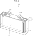
- FIG. 2 is a diagram illustrating an example of a configuration of a cell that is a lithium-ion battery
- FIG. 3 is a diagram schematically illustrating a discharging mechanism of a battery
- FIG. 4 is a diagram for explaining the distribution of lithium ions in the positive electrode active material
- FIG. 5 is a diagram illustrating an example of a change in OCV and CCV of a battery during discharging
- FIG. 6 is a diagram for explaining a resistance component of an internal resistance of a battery
- FIG. 7 is a diagram for explaining a voltage drop of a battery
- FIG. 8 is a diagram for explaining a voltage drop of a battery when the battery is intermittently discharged
- FIG. 9 is a diagram for explaining an outline of a method of calculating a polarization overvoltage
- FIG. 10 is a flowchart illustrating a processing procedure of a polarization overvoltage calculation process according to Embodiment 1;
- FIG. 11 is a conceptual diagram of a map used for calculating a sum of a DC resistance and a reactive resistance
- FIG. 12 is a diagram for explaining responsiveness of impedance of a battery
- FIG. 13 is a diagram for explaining uneven distribution of lithium ions in a positive electrode active material
- FIG. 14 is a flowchart illustrating a processing procedure of discharge power suppression processing in Embodiment 2;
- FIG. 15 is a diagram for explaining the relationship between the actual SOC and the surface SOC
- FIG. 16 is a diagram illustrating an example of a process of calculating a surface SOC from a surface voltage
- FIG. 17 is a diagram for explaining suppression of discharge power according to the surface SOC
- FIG. 18 is a flowchart illustrating a processing procedure of the display processing according to the third embodiment.
- FIG. 19 is a diagram illustrating an example of a display mode of the surface SOC of the battery in the HMI.
- FIG. 20 is a diagram illustrating an example of a display mode of the polarization level of the battery in the HMI.
- the use of the battery system according to the present disclosure is not limited to a vehicle, and may be another use such as a stationary use.
- the vehicle 1 includes a battery pack 2 , a drive system 3 , a charging system 4 , a Human Machine Interface (HMI) 5 , and an Electric Vehicle Electronic Control Unit (EV ECU) 6 .
- the battery pack 2 includes a battery 21 , a monitoring unit 22 , a system main relay (SMR) 23 , and a battery ECU 24 .
- the drive system 3 includes a power control unit (PCU) 31 , motor generators 32 , power transmission gears 33 , and drive wheels 34 .
- the charging system 4 includes an inlet 41 , a power conversion device 42 , and a charging relay 43 .
- the monitoring unit 22 includes various sensors for monitoring the battery 21 .
- the monitoring unit 22 includes a voltage sensor 221 , a current sensor 222 , and a temperature sensor 223 .
- the voltage sensor 221 detects the voltage V B of the cells 211 .
- the current sensor 222 detects a current I B charged to and discharged from the battery 21 . In the present embodiment, the discharge current is set to a positive value.
- the temperature sensor 223 detects a temperature T B of the battery 21 .
- the sensor outputs a signal indicating the detection result to the battery ECU 24 .
- the charge relays 43 are electrically connected to a power line connecting SMR 23 and PCU 31 .
- the charge-relay 43 is opened and closed in accordance with a command from EV ECU 6 .
- the negative electrode is a belt-shaped sheet.
- the negative electrode includes a negative electrode current collector and a negative electrode mixture layer.
- the negative electrode current collector is electrically connected to the negative electrode terminal 712 B.
- the negative electrode current collector is, for example, a copper (Cu) foil.
- the negative electrode mixture layer is formed on the surface of the negative electrode current collector.
- the negative electrode mixture layer may be formed on both surfaces of the front surface and the back surface of the negative electrode current collector.
- the negative electrode mixture layer includes a negative electrode active material and a binder.
- the separator is a strip of film.
- the separator is disposed between the positive electrode and the negative electrode, and electrically insulates the positive electrode and the negative electrode.
- the material of the separator is a porous material, for example polyethylene (PE), polypropylene (PP).
- the specific configuration (the number of cells, the manner of connecting the cells, and the like) of the battery 21 is not particularly limited. Therefore, for the sake of simplicity of explanation, the control target of charging and discharging by the battery ECU 24 and the monitoring target by the monitoring unit 22 will be simply referred to as “battery 21 ” hereinafter.
- FIG. 3 is a diagram schematically illustrating a discharging mechanism of the battery 21 .
- lithium ions deorbed from the negative electrode, while lithium ions are inserted into the positive electrode.
- a description will be given using a “one-particle model” in which a positive electrode active material included in a positive electrode is schematically represented by one particle.
- FIG. 4 is a diagram for explaining the distribution of lithium ions in the positive electrode active material.
- the lithium ions are uniformly distributed in the positive electrode active material.
- the battery 21 is discharged, lithium ions are inserted into the positive electrode active material from a specific direction (a direction from the negative electrode toward the positive electrode). Therefore, lithium ions are unevenly distributed in the positive electrode active material (polarization state). More specifically, the lithium ions become dense in a region near the insertion point of the lithium ions into the positive electrode active material. On the other hand, the lithium ions become sparse in the region away from the insertion point of the lithium ions into the positive electrode active material.
- the OCV of the battery 21 monotonically decreases as the discharge proceeds.
- the CCV of the battery 21 may vary depending on the discharge current. As the uneven distribution of lithium ions progresses, the internal resistance R increases and the amount of voltage drop increases. The CCV then deviates from the OCV. When the CCV falls below a lower limit voltage determined in accordance with characteristics of the negative electrode material or the like, the battery 21 is brought into an over-discharge state. As a result, there is a possibility that copper ions are eluted from the copper foil of the negative electrode current collector or the SEI film is decomposed.
- FIG. 6 is a diagram for explaining an impedance component of an internal resistance of the battery 21 .
- FIG. 6 shows an example of an equivalent circuit diagram of a positive electrode, a negative electrode, and a separator of the battery 21 (each cell 211 ).
- the impedance components of the battery 21 can be classified into DC resistances R DC , reactive resistances Rc, and diffusion resistances Rd.
- the DC resistance R DC is an impedance-component associated with the transfer of lithium-ions and electrons between the positive and negative electrodes.
- the DC resistance R DC is increased due to a deviation such as a salt concentration distribution of the electrolyte solution when a high load is applied to the battery 21 (when a high voltage is applied or a large current flows).
- the DC resistance R DC is represented in the equivalent circuit diagram as the active material resistance Ra 1 of the positive electrode, the active material resistance Ra 2 of the negative electrode, and the electrolyte resistance R 3 of the separator.
- the reactive resistance Rc is an impedance component related to transfer of charge (charge transfer) at the interface between the electrolyte and the active material interface (the surfaces of the positive electrode active material and the negative electrode active material).
- the reactive resistance Rc increases due to, for example, growth of a coating film at an active material/electrolyte interface when the battery 21 in a high SOC state is in a high-temperature environment.
- the reactive resistance Rc is represented as a resistance component Rc 1 of the positive electrode and a resistance component Rc 2 of the negative electrode.
- the diffusion resistance Rd is an impedance component related to diffusion of a salt in an electrolytic solution or a charge transport material in an active material.
- the diffusion resistance Rd increases due to cracking of the active material when a high load is applied.
- the diffusion resistance Rd is determined from the balanced voltage Veq 1 generated in the positive electrode, the balanced voltage Veq 2 generated in the negative electrode, and the salt concentration overvoltage Vov 3 generated in the cell (the overvoltage caused by the salt concentration distribution of the active material occurring in the separators).
- each impedance component is divided into a positive electrode side and a negative electrode side.
- the positive electrode side and the negative electrode side are not particularly distinguished from each other. That is, an impedance component in which the impedance component on the positive electrode side and the impedance component on the negative electrode side are integrated is used.
- FIG. 7 is a diagram for explaining a voltage drop of the battery 21 .
- the horizontal axis represents the elapsed time from the start of discharge.
- the vertical axis represents voltage. The same applies to FIG. 8 described later.
- the battery 21 is discharged continuously with a large current of several hundred amperes (A) in a period from the time t 10 to the time t 11 (for example, several minutes to several tens of minutes).
- the voltage drop amount during the discharging period can be classified into an OCV drop amount ⁇ OCV, a voltage drop amount ⁇ V DC caused by the DC resistance R DC , a voltage drop amount ⁇ Vc caused by the reactive resistance Rc, and a voltage drop amount ⁇ Vd caused by the diffusion resistance Rd.
- the voltage drop amount during discharging is the sum of the OCV drop amount, the voltage drop amount ⁇ V DC , ⁇ Vc, ⁇ Vd caused by the three impedance components.
- ⁇ OCV, ⁇ V DC , and ⁇ Vc and ⁇ Vd are both positive values.
- FIG. 8 is a diagram for explaining a voltage drop of the battery 21 when the battery 21 is intermittently discharged.
- the battery 21 is discharged with a large current during a period from the time t 20 to the time t 21 .
- This discharge is referred to as “first discharge”.
- the discharge is stopped.
- the battery 21 is discharged again with a large current.
- This discharge is referred to as “second discharge”.
- the index (1) of the parameter indicates that the parameter relates to the first discharge.
- the parameter index (2) indicates that the parameter relates to the second discharge.
- the voltage drop amount accompanying the first discharge is the sum of the OCV drop amount ⁇ OCV(1), the voltage drop amount ⁇ V DC (1) caused by the DC resistance R DC , the voltage drop amount ⁇ Vc(1) caused by the reactive resistance Rc, and the voltage drop amount ⁇ Vd(1) caused by the diffusion resistance Rd, as described in FIG. 7 .
- the voltage drop amount due to the second discharge is the sum of the OCV drop amount ⁇ OCV(2), the voltage drop amount ⁇ V DC (2) due to the DC resistance R DC , the voltage drop amount ⁇ Vc(2) due to the reactive resistance Rc, and the voltage drop amount due to the diffusion resistance Rd.
- the voltage drop amount ⁇ Vd(1) caused by the diffusion resistance Rd generated in association with the first discharge is also taken over by the second discharge.
- the voltage drop amount ⁇ Vd(1) caused by the diffusion resistance Rd is accumulated. Therefore, the voltage drop amount caused by the diffusion resistance Rd in the second discharge is the sum of the voltage drop amount ⁇ Vd(1) caused by the diffusion resistance Rd taken over from the first discharge and the voltage drop amount ⁇ Vd(2) caused by the diffusion resistance Rd newly generated in the second discharge.
- the voltage drop amount ( ⁇ Vd(1)+ ⁇ Vd(2)) caused by the diffusion resistance Rd at the time of the second discharge reflects the polarization level (the degree of generation/elimination of polarization) in the battery 21 , that is, the degree of polarization generated in accordance with the first discharge, the degree of polarization relaxed in accordance with the discharge stop between the first discharge and the second discharge, and the degree of polarization generated in accordance with the second discharge. Therefore, the amount of voltage drop caused by the diffusion resistance Rd is hereinafter referred to as “polarization overvoltage ⁇ Vp”.
- the polarization overvoltage ⁇ Vp can be indirectly calculated using a voltage drop amount caused by another impedance component, as described below.
- FIG. 9 is a diagram for explaining an outline of a calculation method of the polarization overvoltage Vp.
- the horizontal axis represents the SOC of the battery 21 .
- the vertical axis represents voltage.
- OCV-SOC curve is indicated by a broken line
- CCV-SOC curve is indicated by a solid line when the battery 21 is discharged from a state close to a state of being fully charged.
- the voltage differential between OCV and CCV (OCV ⁇ V B ) is the sum of the voltage drop caused by the DC resistance R DC and the reactive resistance Rc ( ⁇ V DC + ⁇ Vc) and the polarization overvoltage ⁇ Vp. Therefore, the polarization overvoltage Vp is calculated by returning (subtracting) the current drop ( ⁇ V DC + ⁇ Vc) caused by the DC resistance R DC and the reactive resistance Rc from the voltage difference (OCV ⁇ V B ) between the OCV and the CCV (see Equation (1) below).
- ⁇ Vp (OCV ⁇ V B ) ⁇ ( ⁇ V DC + ⁇ Vc ) (1)
- the OCV can be calculated based on the SOC at the start of discharge of the battery 21 and the integrated value ⁇ Ah of the discharge current (details will be described later).
- the voltage drop amounts ( ⁇ V DC + ⁇ Vc) caused by the DC resistance R DC and the reactive resistance Rc can also be calculated using a map MP 1 (see FIG. 11 ) described later. Therefore, the polarization overvoltage ⁇ Vp can be calculated according to the above equation (1).
- FIG. 10 is a flowchart illustrating a processing procedure of a calculation process of the polarization overvoltage ⁇ Vp according to the first embodiment. This flowchart is executed when a predetermined condition is satisfied (for example, every predetermined cycle). The steps are implemented by software-processing by a battery ECU 24 (processor 241 ), but may also be implemented by hardware (electric circuitry) disposed in a battery ECU 24 .
- the term “step” is abbreviated as S. The same applies to other flowcharts described later.
- the battery ECU 24 determines whether the battery 21 is discharging. While the battery is being charged (NO in S 101 ), another flow (not shown) for charging is executed. When the battery 21 is discharging (YES in S 101 ), the battery ECU 24 acquires the voltage V B from the voltage sensor 221 , acquires the current I B from the current sensor 222 , and acquires the temperature T B from the temperature sensor 223 (S 102 ).
- the battery ECU 24 acquires the SOCs of the battery 21 calculated in accordance with another flow chart (not shown). More specifically, the cell ECU 24 performs the following process. When the battery 21 is not charged or discharged and a certain period of time (for example, several tens of minutes) elapses, the polarization is sufficiently relaxed (i.e., eliminated). The battery ECU 24 calculates the SOC (initial SOC) of the battery 21 from the OCV by referring to OCV-SOC curve stored in advance in the memory 242 with the detected value of the voltage sensor 221 in the depolarized state as the OCV. The full charge capacity of the battery 21 is known.
- the battery ECU 24 can calculate the capacity (Ah) of the battery 21 in the depolarized state from the initial-SOC and the full-charge capacity.
- the battery ECU 24 integrates the discharge current from the depolarized state (the time point at which the initial-SOC is calculated).
- the battery ECU 24 can calculate the current capacity of the battery 21 by subtracting the integrated value ⁇ Ah of the discharging current from the capacity in the depolarized state. Further, the battery ECU 24 can calculate the SOCs of the battery 21 at the present time from the ratio of the current capacity to the full charge capacity.
- the cell ECU 24 calculates the OCVs of the current battery 21 .
- the cell ECU 24 can calculate the OCV from the current SOC acquired by S 103 by referring to OCV-SOC curve.
- the cell ECU 24 calculates a “deterioration index” which is an index indicating the degree of progress of deterioration of the battery 21 .
- the deterioration index is the number of years elapsed since the time of manufacture of the battery 21 .
- the deterioration index is not limited to this, and may be the total travel distance of the vehicle 1 .
- the deterioration index may be a value determined according to both the number of years elapsed since the time of manufacture of the battery 21 and the total travel distance of the vehicle 1 .
- the battery ECU 24 calculates the sum (R DC +R c ) of the DC resistance R DC of the battery 21 and the reactive resistance Rc based on the temperature T B , the SOC, and the degradation index of the battery 21 .
- the following map MP 1 can be used to calculate the sum (R DC +Rc). Note that a table, a function, or a conversion formula may be used instead of the map. The same applies to other map MP 2 ,MP 3 (see FIGS. 16 and 17 ) shown later.
- FIG. 11 is a conceptual diagram of a map MP 1 used for calculating a sum (R DC +Rc) of a DC resistance R DC and a reactive resistance Rc.
- the map MP 1 has a data format in which the correlation between the temperature T B and the SOC and the above sum (R DC +Rc) is defined for each degradation index (e.g., one year after manufacture of the battery 21 , two years, three years, etc.).
- the degradation index e.g., one year after manufacture of the battery 21 , two years, three years, etc.
- the lower the SOCs and the lower the T B the higher the sum of the DC resistance R DC and the reactive resistance Rc (R DC +Rc).
- the map MP 1 corresponds to a “correlation” according to the present disclosure.
- a method of creating a map MP 1 will be described.
- a plurality of batteries (batteries of the same type as the battery 21 ) having different deterioration indices are prepared. Then, for each of the plurality of batteries, a voltage response after a predetermined time when a current is applied to the battery is measured. The current response at the time of voltage application may be measured. The impedance is calculated from the ratio between the voltage and the current.
- FIG. 12 is a diagram for explaining responsiveness of impedance of a battery.
- an alternating current is applied to the battery.
- the horizontal axis represents the frequency of the alternating current applied to the battery.
- the vertical axis represents the impedance of the battery.
- the internal resistance of the battery includes various impedance components.
- a time (response time) required for a response to an applied current is different.
- the impedance component having a relatively short response time can also follow changes in the alternating current at high frequencies.
- an impedance component having a relatively long response time cannot follow a change in an alternating current at a high frequency. Therefore, when the frequency range is divided into a low frequency range, a middle frequency range, and a high frequency range, the dominant impedance component can be divided in each frequency range.
- a frequency range of 5 Hz or more and 100 kHz or less (a response time of 10 microseconds or more and less than 0.2 seconds) is referred to as a “high frequency range”.
- a frequency range of 1 Hz or more and 5 Hz or less (response time 0.2 seconds or more and less than 1 second) is referred to as a “medium frequency range”.
- a frequency range of more than 10 mHz and 1 Hz or less (response time of 1 second or more and less than 100 seconds) is referred to as a “low frequency range”.
- the impedance components measured when the frequency of the alternating current is in the high frequency range mainly include a DC resistance R DC of the battery.
- the impedance components measured when the frequency of the alternating current is in the mid-frequency range mainly include a DC resistance R DC and a reactive resistance Rc.
- the impedance components measured when the frequency of the alternating current is within the low frequency range include both the DC resistance R DC , the response resistance Rc, and the diffusion resistance Rd. Therefore, the sum of the DC resistance R DC and the reactive resistance Rc (R DC +Rc) can be obtained from the measured impedance of the battery in the mid-frequency range.
- the response time (0.2 seconds or more and less than 1 second) in the mid-frequency range is longer than the time when the DC resistance R DC and the reactive resistance Rc of the battery can follow the change in the AC current, and the diffusion resistance Rd of the battery is shorter than the time when the diffusion resistance Rd of the battery can follow the change in the AC current.
- Map MP 1 can be created by performing impedance-measurements under various combinations of temperature-SOC conditions for each battery with differing degradation indices. By referring to the map MP 1 , it is possible to calculate the sum (R DC +Rc) of the DC resistance R DC of the battery 21 and the reactive resistance Rc from the temperature T B of the battery 21 , the SOC, and the degradation index.
- the degradation index is not a parameter for the map MP 1 .
- the map MP 1 includes the deterioration index, the degree of progress of the deterioration of the battery 21 (increased resistance due to deterioration) is reflected in the sum (R DC +Rc), so that it is possible to improve the calculation accuracy of the sum (R DC +Rc).
- the cell ECU 24 calculates the diffusion resistance Rd based on the polarization overvoltage ⁇ Vp.
- Rd ⁇ (OCV ⁇ V B )— I B ⁇ ( R DC ⁇ Rc ) ⁇ / I B (2)
- the detected value (I B ) of the current sensor 222 can be easily converted from one to the other.
- the calculation of the polarization overvoltage Vp corresponds to displaying the polarization level (the degree of generation/elimination of polarization) of the battery 21 as a voltage.
- the calculation of the diffusion resistance Rd corresponds to displaying the polarization level of the battery 21 as a resistance.
- the “calculation of the polarization overvoltage” in the present disclosure is not limited to the configuration in which the polarization overvoltage ⁇ Vp is calculated according to Equation (1), but also includes a configuration in which the diffusion resistance Rd is calculated according to Equation (2).
- JP 2013-221790 A the internal resistance is divided into a DC resistance component and a polarization resistance component (see paragraphs [0042] to [0044] of JP 2013-221790 A).
- the polarization resistance component is considered to include both the reactive resistance component and the diffusion resistance component.
- the voltage drop caused by the DC resistance and the voltage drop caused by the reactive resistance are always generated while the discharge current is flowing, regardless of whether the polarization is generated or eliminated. That is, in the disclosure disclosed in JP 2013-221790 A, there is room for improvement in the calculation accuracy of the voltage drop amount due to polarization by an amount including the voltage drop amount caused by the reactive resistance irrelevant to polarization.
- the reactive resistance Rc is more temperature-dependent than the DC resistance R DC .
- DC resistance R DC does not increase much under normal temperature conditions and under low temperature conditions, whereas reactive resistance Rc increases significantly under normal temperature conditions compared to under low temperature conditions.
- the reactive resistance Rc tends to increase over time by an amount that is more susceptible to thermal changes than the DC resistance R DC (so-called aging degradation). Therefore, when the polarization resistance component is included in the reactive resistance component as in JP 2013-221790 A, errors due to temperature change and/or aging deterioration are likely to occur.
- the polarization overvoltage Vp is calculated by subtracting the voltage drop ( ⁇ V DC + ⁇ Vc) caused by the DC resistance R DC and the response resistance Rc from the voltage difference (OCV ⁇ V B ) between the OCV and the CCV.
- the polarization overvoltage ⁇ Vp does not include not only the voltage drop amount ⁇ Vc caused by the DC resistance R DC but also the voltage drop amount ⁇ Vc caused by the response resistance Rc.
- the voltage drop amount ⁇ Vc caused by the reactive resistance Rc is excluded from the polarization overvoltage ⁇ Vp.
- the first embodiment it is possible to accurately calculate the amount of voltage drop due to polarization during discharge of the battery 21 .
- FIG. 13 is a diagram for explaining uneven distribution of lithium ions in the positive electrode active material.
- FIG. 4 when the battery 21 is discharged at a large current, lithium ions are unevenly distributed in the positive electrode active material (polarization state). When the discharge is stopped, the diffusion of lithium ions in the positive electrode active material proceeds, and the polarization is relaxed. When a certain period of time elapses, the distribution of lithium ions in the positive electrode active material becomes uniform, and the polarization is eliminated (unloaded state).
- the SOC is represented by the number of white circles representing lithium ions.
- the SOC is high, the total amount of lithium ions (the number of circles) is smaller than when the SOC is low.
- the region in which the lithium ions are unevenly distributed even in the high SOC includes the lithium ions having the same density as the region in which the lithium ions are uniformly distributed in the low SOC. Therefore, when these two regions are compared, the amount of lithium ions that can be newly received (inserted) is also comparable. This means that the discharge capacity of the battery 21 (electric power dischargeable from the battery 21 ) is equivalent between the high SOC and the polarization state and the low SOC and the no-load state.
- the SOC in the polarization state is represented by the SOC in the unloaded state in which the discharging capability is the same. Whether lithium ions can be newly accepted depends on the amount of lithium ions present on the surface of the active material. Therefore, in the following, the SOC in the polarization state is also referred to as “surface SOC”.
- FIG. 14 is a flowchart illustrating a processing procedure of discharge power suppression processing according to Embodiment 2.
- a series of processes executed by the battery ECU 24 is shown on the left, and a series of processes executed by EV ECU 6 is shown on the right.
- S 201 to S 207 process is the same as S 101 to S 107 process (see FIG. 10 ) in Embodiment 1, and therefore will not be described again.
- the cell ECU 24 calculates the “surface voltage Vs” defined by using the polarization overvoltage ⁇ Vp calculated by S 207 .
- the surface voltage Vs is a voltage obtained by subtracting the polarization overvoltage ⁇ Vp from the OCV as shown in the following equation (3).
- the surface voltage Vs coincides with the OCV.
- the polarization overvoltage ⁇ Vp increases, the deviation of the surface voltage Vs from the OCV proceeds. That is, as the polarization proceeds, the surface voltage Vs decreases.
- Vs OCV ⁇ Vp (3)
- the cell ECU 24 calculates the surface SOCs based on the surface voltages Vs. A method of calculating the surface SOC will be described below. In order to distinguish it from the surface SOC, the commonly used SOC (SOC determined according to the total amount of lithium ions in the positive electrode active material) is also referred to as “actual SOC”.
- FIG. 15 is a diagram for explaining the relationship between the actual SOC and the surface SOC.
- the horizontal axis represents actual SOC.
- the vertical axis represents voltage.
- Two curve L 1 ,L 2 are shown in FIG. 15 .
- the rate of change of the curve L 1 and the rate of change of the curve L 2 are approximately equal.
- the rate of change is the amount of voltage drop per unit SOC corresponding to the slope of the tangent line (not shown).
- the rate of change is approximately equal because the polarization overvoltage ⁇ Vp is approximately equal between curve L 1 and curve L 2 .
- the battery 21 can be discharged only at a level equivalent to the actual SOC in the unloaded state of 10%. Therefore, in the second embodiment, when the actual SOC is 50%, the discharge power from the battery 21 is suppressed as if the actual SOC is 10%.
- the surface SOC is introduced in order to suppress the discharge power.
- the surface SOC is a parameter representing the SOC in the polarization state of the battery 21 by the SOC in the unloaded state in which the discharging capability is equivalent.
- the surface SOC is calculated from the actual SOC by using the “shift amount ⁇ SOC” as shown in the following Expression (4).
- the actual SOC is 50%, and the shift amount ⁇ SOC is calculated to be 40% from the surface voltage Vs at that time.
- FIG. 16 is a diagram illustrating an example of a process of calculating the surface SOC from the surface voltage Vs.
- the horizontal axis represents the surface voltage Vs.
- the vertical axis represents the shift amount ⁇ SOC.
- the relation between the surface-voltage Vs and the shift amount ⁇ SOC as shown in FIG. 16 is stored in the memory 242 of the battery ECU 24 as a map MP 2 , for example.
- the cell ECU 24 can calculate the shift amount ⁇ SOC from the surface-voltage Vs by referring to the map MP 2 .
- the cell ECU 24 sets the upper-limit discharging power Wout according to the surface-SOC.
- the battery ECU 24 outputs the set upper limit discharging power Wout to EV ECU 6 .
- EV ECU 6 suppresses the discharge power from the battery 21 in accordance with the upper limit discharge power Wout received from the battery ECU 24 (S 301 ).
- FIG. 17 is a diagram for explaining suppression of discharge power according to the surface SOC.
- the horizontal axis represents the actual SOC or surface SOC.
- the vertical axis represents the upper limit discharging power Wout.
- the relation between the upper limit discharging power Wout and the SOC (actual SOC or surface SOC) as shown in FIG. 17 is stored in the memories 242 of the cell ECU 24 as a map MP 3 , for example.
- the cell ECU 24 reads the horizontal axis of the map MP 3 as the actual SOC or the surface SOC, only one type of map MP 3 needs to be prepared. That is, it is not necessary to prepare the map for the actual SOC and the map for the surface SOC separately. Therefore, the calculation process of the cell ECU 24 can be simplified.
- the surface voltage Vs is calculated in accordance with the polarization overvoltage Vp (see Equation (3)). Further, the surface SOC is calculated from the shift amount ⁇ SOC corresponding to the surface voltage Vs (see FIG. 16 ). As described in detail with reference to FIG. 13 , the surface SOC is determined in accordance with the local density of lithium ions in the portion where the deviation occurs when the deviation of lithium ions occurs in the positive electrode active material. On the other hand, the actual SOC is determined in accordance with the density of lithium ions in the case of being uniformly distributed in the positive electrode active material. In the present embodiment, the surface SOC in the polarization state and the actual SOC in the no-load state are associated with each other by the method described in FIGS.
- the upper limit discharging power Wout is set in accordance with the surface SOC instead of the actual SOC (see FIG. 17 ). Therefore, according to the second embodiment, the discharge power can be suppressed according to the degree of occurrence of the actual polarization of the battery 21 .
- the third embodiment a configuration for displaying parameters related to the polarization level of the battery 21 , such as the surface SOC of the battery 21 and the polarization overvoltage ⁇ Vp, will be described.
- the overall configuration of the vehicle on which the battery system according to the third embodiment is mounted is the same as the overall configuration of the vehicle 1 on which the battery pack 2 according to the first embodiment is mounted (see FIG. 1 ).
- FIG. 18 is a flowchart illustrating a processing procedure of the display processing according to the third embodiment.
- Processing of S 401 to S 405 is the same as the processing (see FIG. 14 ) of S 201 to S 210 in Embodiment 2.
- the process of S 202 to S 207 in the second embodiment is typically illustrated by the process of S 402 for convenience of the paper.
- the cell ECU 24 outputs the polarization overvoltage ⁇ Vp calculated by S 402 process to EV ECU 6 .
- the cell ECU 24 outputs the surface-SOC calculated by S 404 process to EV ECU 6 .
- the cell ECU 24 outputs the upper limit discharging power Wout calculated by S 405 process to EV ECU 6 .
- the cell ECU 24 can calculate the OCV(n) after n seconds from the actual SOC(n) after n seconds by referring to SOC-OCV curve.
- V B For a voltage V B , it can be assumed, for example, that the voltage drops at a constant rate equal to the drop rate of the present voltage V B . It can also be assumed that (R DC +Rc) is maintained at present. Then, the cell ECU 24 can calculate the polarization overvoltage ⁇ Vp(n) after n seconds according to the above equation (1).
- Vs(n) after n seconds is calculated by substituting OCV(n) after n seconds and the polarization overvoltage ⁇ Vp(n) after n seconds into Equation (3) (described again).
- Vs ( n ) ⁇ OCV( n ) ⁇ Vp ( n ) (3)
- the cell ECU 24 calculates the surface SOC(n) after n seconds from the surface voltage Vs(n) after n seconds using the map MP 2 (see FIG. 16 ) (see Equation (4)). Subsequently, the cell ECU 24 calculates the upper limit discharging power Wout after n seconds from the surface-SOC(n) after n seconds using the map MP 3 (see FIG. 17 ). Accordingly, the battery ECU 24 can calculate the time at which the discharge power reaches the upper limit discharge power Wout for the first time when the discharge power from the battery 21 is maintained at the present value. The time from the present time until the time when the discharge power reaches the upper limit discharge power Wout for the first time can be set as the vehicle speed maintenance time. The cell ECU 24 outputs the calculated vehicle speed maintenance times to EV ECU 6 .
- EV ECU 6 controls HMI 5 (e.g., the instrument panel) to indicate the surface-SOC of the battery 21 . Further, in S 503 , EV ECU 6 controls HMI 5 to indicate the polarization level of the battery 21 in response to the polarization overvoltage ⁇ Vp.
- HMI 5 e.g., the instrument panel
- three icons are used. If the polarization overvoltage ⁇ Vp is greater than the first reference value, a left icon is displayed indicating that the lithium ions are unevenly distributed, assuming that a large polarization has occurred. When the polarization overvoltage ⁇ Vp is smaller than the second reference value ( ⁇ the first reference value), the right icon indicating that the polarization has been eliminated is displayed, indicating that the lithium ions are uniformly distributed. If the polarization overvoltage ⁇ Vp is greater than the second reference value and within a range smaller than the first reference value, a central icon indicating that the lithium ions are diffusing is displayed assuming that the polarization is being relaxed.
- the driver of the vehicle 1 can understand that the polarization of the battery 21 is occurring with discharging at a high current or with continuous discharging. Conversely, the driver can understand that the polarization of the battery 21 is relaxed over time during the period in which the discharge of the battery 21 is stopped.
- EV ECU 6 controls HMI 5 to indicate the upper limit discharging power Wout.
- EV ECU 6 may also display the actual discharge power on HMI 5 , or may display the difference between the upper limit discharge power Wout and the actual discharge power on HMI 5 .
- EV ECU 6 controls HMI 5 to indicate the vehicle speed maintenance times (S 505 ).
- EV ECU 6 may simultaneously display the four parameters of the surface-SOC, the polarization-level, the upper-limit discharging power Wout, and the vehicle-speed maintenance-time on HMI 5 or may display them in order.
- EV ECU 6 may display some of the four parameters, e.g., on the instrument panel, and the rest, e.g., on the HUDs.
- EV ECU 6 may not display all of the four parameters in HMI 5 , and may display only any one, only two, or only three of the four parameters in HMI 5 .
- the third embodiment at least one of the surface-SOC, the polarization-level, the upper-limit discharging power Wout, and the vehicle-speed maintenance-time of the battery 21 is displayed on HMI 5 .
- the driver can understand the polarization state of the battery 21 .
- the upper limit discharge power Wout the driver can understand the possibility that the discharge power is suppressed.
- the vehicle speed maintenance time the driver can recognize the timing at which the discharge power is suppressed. Therefore, according to the third embodiment, it is possible to prevent the driver from erroneously recognizing that a defect has occurred in the vehicle 1 .
- the driver can operate the vehicle according to the polarization level of the battery 21 .
Landscapes
- Engineering & Computer Science (AREA)
- General Chemical & Material Sciences (AREA)
- Power Engineering (AREA)
- Manufacturing & Machinery (AREA)
- Chemical & Material Sciences (AREA)
- Chemical Kinetics & Catalysis (AREA)
- Electrochemistry (AREA)
- Physics & Mathematics (AREA)
- General Physics & Mathematics (AREA)
- Microelectronics & Electronic Packaging (AREA)
- Secondary Cells (AREA)
- Health & Medical Sciences (AREA)
- General Health & Medical Sciences (AREA)
- Medical Informatics (AREA)
- Electric Propulsion And Braking For Vehicles (AREA)
- Tests Of Electric Status Of Batteries (AREA)
- Charge And Discharge Circuits For Batteries Or The Like (AREA)
Abstract
Description
ΔVp=(OCV−V B)−(ΔV DC +ΔVc) (1)
ΔVp=(OCV−V B)—I B×(R DC +Rc) (1)
Rd={(OCV−V B)—I B×(R DC ±Rc)}/I B (2)
Vs=OCV−ΔVp (3)
Surface SOC=actual SOC-ΔSOC= (4)
ΔVp=(OCV−V B)−I B×(R DC +Rc) (1)
Vs(n)Δ=OCV(n)−ΔVp(n) (3)
Claims (11)
Applications Claiming Priority (2)
| Application Number | Priority Date | Filing Date | Title |
|---|---|---|---|
| JP2021-206078 | 2021-12-20 | ||
| JP2021206078A JP7571720B2 (en) | 2021-12-20 | 2021-12-20 | Battery system, vehicle equipped with same, and method for monitoring secondary battery |
Publications (2)
| Publication Number | Publication Date |
|---|---|
| US20230194619A1 US20230194619A1 (en) | 2023-06-22 |
| US12061239B2 true US12061239B2 (en) | 2024-08-13 |
Family
ID=86767760
Family Applications (1)
| Application Number | Title | Priority Date | Filing Date |
|---|---|---|---|
| US17/987,955 Active 2043-03-29 US12061239B2 (en) | 2021-12-20 | 2022-11-16 | Battery system, vehicle including the same, and method for monitoring secondary battery |
Country Status (2)
| Country | Link |
|---|---|
| US (1) | US12061239B2 (en) |
| JP (1) | JP7571720B2 (en) |
Families Citing this family (2)
| Publication number | Priority date | Publication date | Assignee | Title |
|---|---|---|---|---|
| WO2026048525A1 (en) * | 2024-08-29 | 2026-03-05 | パナソニックIpマネジメント株式会社 | Battery analysis system, battery analysis method, and battery analysis program |
| WO2026048524A1 (en) * | 2024-08-29 | 2026-03-05 | パナソニックIpマネジメント株式会社 | Battery cell analysis system, battery cell analysis method, and battery cell analysis program |
Citations (4)
| Publication number | Priority date | Publication date | Assignee | Title |
|---|---|---|---|---|
| US20110084702A1 (en) | 2009-10-14 | 2011-04-14 | Sony Corporation | Battery pack and method for detecting degradation of battery |
| US20110279088A1 (en) * | 2009-12-16 | 2011-11-17 | Taisuke Yamamoto | Battery pack, discharge system, charge and discharge system, and discharge control method of lithium ion secondary battery |
| JP2013221790A (en) | 2012-04-13 | 2013-10-28 | Toyota Industries Corp | Battery internal state estimating device mounted on vehicle |
| JP2015121449A (en) | 2013-12-24 | 2015-07-02 | 株式会社デンソー | Charge state estimation device |
Family Cites Families (10)
| Publication number | Priority date | Publication date | Assignee | Title |
|---|---|---|---|---|
| JP2013208034A (en) | 2012-03-29 | 2013-10-07 | Honda Motor Co Ltd | Open-circuit voltage estimation device |
| JP6239241B2 (en) | 2013-02-04 | 2017-11-29 | 株式会社東芝 | Battery performance estimation method and battery performance estimation apparatus |
| JP6376091B2 (en) | 2014-12-26 | 2018-08-22 | 株式会社デンソー | Battery power prediction device |
| CN107066722B (en) | 2017-04-06 | 2020-07-07 | 北京理工大学 | A joint estimation method for the state of charge and state of health of a power battery system based on an electrochemical model |
| JP6863054B2 (en) | 2017-04-28 | 2021-04-21 | トヨタ自動車株式会社 | Rechargeable battery system |
| JP7024448B2 (en) | 2018-01-29 | 2022-02-24 | トヨタ自動車株式会社 | Electric vehicle |
| JP7070251B2 (en) * | 2018-08-29 | 2022-05-18 | トヨタ自動車株式会社 | Rechargeable battery system |
| KR20220039249A (en) | 2020-09-22 | 2022-03-29 | 주식회사 엘지에너지솔루션 | Battery apparatus and method for estimating battery state |
| KR20220045358A (en) | 2020-10-05 | 2022-04-12 | 주식회사 엘지에너지솔루션 | Battery apparatus and method for predicting battery output |
| CN113176503B (en) | 2021-04-23 | 2022-07-12 | 哈尔滨工业大学(威海) | Equivalent Model of Li-ion Battery with Full SOC Range Based on Electrochemical Process |
-
2021
- 2021-12-20 JP JP2021206078A patent/JP7571720B2/en active Active
-
2022
- 2022-11-16 US US17/987,955 patent/US12061239B2/en active Active
Patent Citations (5)
| Publication number | Priority date | Publication date | Assignee | Title |
|---|---|---|---|---|
| US20110084702A1 (en) | 2009-10-14 | 2011-04-14 | Sony Corporation | Battery pack and method for detecting degradation of battery |
| JP2011103291A (en) | 2009-10-14 | 2011-05-26 | Sony Corp | Battery pack and method for detecting degree of battery deterioration |
| US20110279088A1 (en) * | 2009-12-16 | 2011-11-17 | Taisuke Yamamoto | Battery pack, discharge system, charge and discharge system, and discharge control method of lithium ion secondary battery |
| JP2013221790A (en) | 2012-04-13 | 2013-10-28 | Toyota Industries Corp | Battery internal state estimating device mounted on vehicle |
| JP2015121449A (en) | 2013-12-24 | 2015-07-02 | 株式会社デンソー | Charge state estimation device |
Also Published As
| Publication number | Publication date |
|---|---|
| US20230194619A1 (en) | 2023-06-22 |
| JP7571720B2 (en) | 2024-10-23 |
| JP2023091369A (en) | 2023-06-30 |
Similar Documents
| Publication | Publication Date | Title |
|---|---|---|
| CN111542759B (en) | Abnormality detection device for secondary battery, abnormality detection method, and program | |
| US10569660B2 (en) | Systems and methods for battery state-of-health monitoring | |
| CN102369627B (en) | Secondary battery system | |
| JP6192738B2 (en) | Battery module and battery pack | |
| KR101273727B1 (en) | Cell controller and voltage abnormality detecting method | |
| US9496742B2 (en) | Secondary battery control device | |
| US12306260B2 (en) | Battery system and method for evaluating lithium-ion battery degradation | |
| EP3823065A1 (en) | Method for charging battery and charging system | |
| JP2013092398A (en) | Secondary battery deterioration determination system and deterioration determination method | |
| US12061239B2 (en) | Battery system, vehicle including the same, and method for monitoring secondary battery | |
| CN112820957B (en) | Battery charging method and charging system | |
| CN113809412A (en) | battery system | |
| CN110098436A (en) | The deterioration state of secondary battery system and secondary battery system estimates method | |
| JP2020092047A (en) | Secondary battery deterioration degree estimation device and secondary battery deterioration degree estimation method | |
| JP7582273B2 (en) | Battery diagnostic system, vehicle equipped with same, and battery diagnostic method | |
| CN113178625A (en) | Secondary battery diagnosis device and SOC unevenness detection method | |
| JP2015190815A (en) | Lithium ion secondary battery state detection system and lithium ion secondary battery state detection method | |
| EP4481888A2 (en) | Method of managing lithium ion secondary battery and battery management system | |
| JP7409025B2 (en) | Estimation system | |
| JP2020087772A (en) | Charging system | |
| JP7409026B2 (en) | Estimation system | |
| US12282066B2 (en) | Battery diagnosis system, vehicle equipped with the same, and battery diagnosis method | |
| JP7605182B2 (en) | Power Supplies | |
| JP2013055005A (en) | Secondary battery device, and control method of secondary battery device | |
| CN120357061A (en) | Method for controlling charge and discharge of secondary battery |
Legal Events
| Date | Code | Title | Description |
|---|---|---|---|
| FEPP | Fee payment procedure |
Free format text: ENTITY STATUS SET TO UNDISCOUNTED (ORIGINAL EVENT CODE: BIG.); ENTITY STATUS OF PATENT OWNER: LARGE ENTITY |
|
| AS | Assignment |
Owner name: TOYOTA JIDOSHA KABUSHIKI KAISHA, JAPAN Free format text: ASSIGNMENT OF ASSIGNORS INTEREST;ASSIGNORS:SUZUKI, KENTARO;OKANISHI, DAISUKE;NAGAI, HIROKI;AND OTHERS;SIGNING DATES FROM 20220915 TO 20221003;REEL/FRAME:061828/0575 |
|
| STPP | Information on status: patent application and granting procedure in general |
Free format text: DOCKETED NEW CASE - READY FOR EXAMINATION |
|
| STPP | Information on status: patent application and granting procedure in general |
Free format text: NOTICE OF ALLOWANCE MAILED -- APPLICATION RECEIVED IN OFFICE OF PUBLICATIONS |
|
| STPP | Information on status: patent application and granting procedure in general |
Free format text: PUBLICATIONS -- ISSUE FEE PAYMENT RECEIVED |
|
| STPP | Information on status: patent application and granting procedure in general |
Free format text: PUBLICATIONS -- ISSUE FEE PAYMENT VERIFIED |
|
| STCF | Information on status: patent grant |
Free format text: PATENTED CASE |