US12057381B2 - Circuit board having laminated build-up layers - Google Patents
Circuit board having laminated build-up layers Download PDFInfo
- Publication number
- US12057381B2 US12057381B2 US17/498,757 US202117498757A US12057381B2 US 12057381 B2 US12057381 B2 US 12057381B2 US 202117498757 A US202117498757 A US 202117498757A US 12057381 B2 US12057381 B2 US 12057381B2
- Authority
- US
- United States
- Prior art keywords
- layer
- substrate
- conductive
- external circuit
- circuit layer
- Prior art date
- Legal status (The legal status is an assumption and is not a legal conclusion. Google has not performed a legal analysis and makes no representation as to the accuracy of the status listed.)
- Active, expires
Links
Images


Classifications
-
- H01L23/49827—
-
- H—ELECTRICITY
- H05—ELECTRIC TECHNIQUES NOT OTHERWISE PROVIDED FOR
- H05K—PRINTED CIRCUITS; CASINGS OR CONSTRUCTIONAL DETAILS OF ELECTRIC APPARATUS; MANUFACTURE OF ASSEMBLAGES OF ELECTRICAL COMPONENTS
- H05K1/00—Printed circuits
- H05K1/02—Details
- H05K1/11—Printed elements for providing electric connections to or between printed circuits
- H05K1/115—Via connections; Lands around holes or via connections
-
- H01L21/4857—
-
- H01L21/486—
-
- H01L23/49822—
-
- H—ELECTRICITY
- H05—ELECTRIC TECHNIQUES NOT OTHERWISE PROVIDED FOR
- H05K—PRINTED CIRCUITS; CASINGS OR CONSTRUCTIONAL DETAILS OF ELECTRIC APPARATUS; MANUFACTURE OF ASSEMBLAGES OF ELECTRICAL COMPONENTS
- H05K1/00—Printed circuits
- H05K1/02—Details
- H05K1/0213—Electrical arrangements not otherwise provided for
- H05K1/0216—Reduction of cross-talk, noise or electromagnetic interference
- H05K1/0218—Reduction of cross-talk, noise or electromagnetic interference by printed shielding conductors, ground planes or power plane
- H05K1/0219—Printed shielding conductors for shielding around or between signal conductors, e.g. coplanar or coaxial printed shielding conductors
- H05K1/0222—Printed shielding conductors for shielding around or between signal conductors, e.g. coplanar or coaxial printed shielding conductors for shielding around a single via or around a group of vias, e.g. coaxial vias or vias surrounded by a grounded via fence
-
- H—ELECTRICITY
- H05—ELECTRIC TECHNIQUES NOT OTHERWISE PROVIDED FOR
- H05K—PRINTED CIRCUITS; CASINGS OR CONSTRUCTIONAL DETAILS OF ELECTRIC APPARATUS; MANUFACTURE OF ASSEMBLAGES OF ELECTRICAL COMPONENTS
- H05K3/00—Apparatus or processes for manufacturing printed circuits
- H05K3/0094—Filling or covering plated through-holes or blind plated vias, e.g. for masking or for mechanical reinforcement
-
- H—ELECTRICITY
- H05—ELECTRIC TECHNIQUES NOT OTHERWISE PROVIDED FOR
- H05K—PRINTED CIRCUITS; CASINGS OR CONSTRUCTIONAL DETAILS OF ELECTRIC APPARATUS; MANUFACTURE OF ASSEMBLAGES OF ELECTRICAL COMPONENTS
- H05K3/00—Apparatus or processes for manufacturing printed circuits
- H05K3/40—Forming printed elements for providing electric connections to or between printed circuits
- H05K3/42—Plated through-holes or plated via connections
- H05K3/429—Plated through-holes specially for multilayer circuits, e.g. having connections to inner circuit layers
-
- H—ELECTRICITY
- H05—ELECTRIC TECHNIQUES NOT OTHERWISE PROVIDED FOR
- H05K—PRINTED CIRCUITS; CASINGS OR CONSTRUCTIONAL DETAILS OF ELECTRIC APPARATUS; MANUFACTURE OF ASSEMBLAGES OF ELECTRICAL COMPONENTS
- H05K3/00—Apparatus or processes for manufacturing printed circuits
- H05K3/46—Manufacturing multilayer circuits
- H05K3/4611—Manufacturing multilayer circuits by laminating two or more circuit boards
- H05K3/4614—Manufacturing multilayer circuits by laminating two or more circuit boards the electrical connections between the circuit boards being made during lamination
-
- H—ELECTRICITY
- H05—ELECTRIC TECHNIQUES NOT OTHERWISE PROVIDED FOR
- H05K—PRINTED CIRCUITS; CASINGS OR CONSTRUCTIONAL DETAILS OF ELECTRIC APPARATUS; MANUFACTURE OF ASSEMBLAGES OF ELECTRICAL COMPONENTS
- H05K3/00—Apparatus or processes for manufacturing printed circuits
- H05K3/46—Manufacturing multilayer circuits
- H05K3/4611—Manufacturing multilayer circuits by laminating two or more circuit boards
- H05K3/4623—Manufacturing multilayer circuits by laminating two or more circuit boards the circuit boards having internal via connections between two or more circuit layers before lamination, e.g. double-sided circuit boards
-
- H—ELECTRICITY
- H10—SEMICONDUCTOR DEVICES; ELECTRIC SOLID-STATE DEVICES NOT OTHERWISE PROVIDED FOR
- H10W—GENERIC PACKAGES, INTERCONNECTIONS, CONNECTORS OR OTHER CONSTRUCTIONAL DETAILS OF DEVICES COVERED BY CLASS H10
- H10W70/00—Package substrates; Interposers; Redistribution layers [RDL]
- H10W70/01—Manufacture or treatment
- H10W70/05—Manufacture or treatment of insulating or insulated package substrates, or of interposers, or of redistribution layers
- H10W70/095—Manufacture or treatment of insulating or insulated package substrates, or of interposers, or of redistribution layers of vias therein
-
- H—ELECTRICITY
- H10—SEMICONDUCTOR DEVICES; ELECTRIC SOLID-STATE DEVICES NOT OTHERWISE PROVIDED FOR
- H10W—GENERIC PACKAGES, INTERCONNECTIONS, CONNECTORS OR OTHER CONSTRUCTIONAL DETAILS OF DEVICES COVERED BY CLASS H10
- H10W70/00—Package substrates; Interposers; Redistribution layers [RDL]
- H10W70/60—Insulating or insulated package substrates; Interposers; Redistribution layers
- H10W70/62—Insulating or insulated package substrates; Interposers; Redistribution layers characterised by their interconnections
- H10W70/63—Vias, e.g. via plugs
- H10W70/635—Through-vias
-
- H01L2224/16227—
-
- H01L24/16—
-
- H—ELECTRICITY
- H05—ELECTRIC TECHNIQUES NOT OTHERWISE PROVIDED FOR
- H05K—PRINTED CIRCUITS; CASINGS OR CONSTRUCTIONAL DETAILS OF ELECTRIC APPARATUS; MANUFACTURE OF ASSEMBLAGES OF ELECTRICAL COMPONENTS
- H05K1/00—Printed circuits
- H05K1/02—Details
- H05K1/0213—Electrical arrangements not otherwise provided for
- H05K1/0216—Reduction of cross-talk, noise or electromagnetic interference
- H05K1/0218—Reduction of cross-talk, noise or electromagnetic interference by printed shielding conductors, ground planes or power plane
- H05K1/0219—Printed shielding conductors for shielding around or between signal conductors, e.g. coplanar or coaxial printed shielding conductors
-
- H—ELECTRICITY
- H05—ELECTRIC TECHNIQUES NOT OTHERWISE PROVIDED FOR
- H05K—PRINTED CIRCUITS; CASINGS OR CONSTRUCTIONAL DETAILS OF ELECTRIC APPARATUS; MANUFACTURE OF ASSEMBLAGES OF ELECTRICAL COMPONENTS
- H05K1/00—Printed circuits
- H05K1/02—Details
- H05K1/0213—Electrical arrangements not otherwise provided for
- H05K1/0237—High frequency adaptations
- H05K1/024—Dielectric details, e.g. changing the dielectric material around a transmission line
-
- H—ELECTRICITY
- H05—ELECTRIC TECHNIQUES NOT OTHERWISE PROVIDED FOR
- H05K—PRINTED CIRCUITS; CASINGS OR CONSTRUCTIONAL DETAILS OF ELECTRIC APPARATUS; MANUFACTURE OF ASSEMBLAGES OF ELECTRICAL COMPONENTS
- H05K1/00—Printed circuits
- H05K1/02—Details
- H05K1/11—Printed elements for providing electric connections to or between printed circuits
- H05K1/111—Pads for surface mounting, e.g. lay-out
- H05K1/112—Pads for surface mounting, e.g. lay-out directly combined with via connections
- H05K1/113—Via provided in pad; Pad over filled via
-
- H—ELECTRICITY
- H05—ELECTRIC TECHNIQUES NOT OTHERWISE PROVIDED FOR
- H05K—PRINTED CIRCUITS; CASINGS OR CONSTRUCTIONAL DETAILS OF ELECTRIC APPARATUS; MANUFACTURE OF ASSEMBLAGES OF ELECTRICAL COMPONENTS
- H05K2201/00—Indexing scheme relating to printed circuits covered by H05K1/00
- H05K2201/01—Dielectrics
- H05K2201/0183—Dielectric layers
- H05K2201/0187—Dielectric layers with regions of different dielectrics in the same layer, e.g. in a printed capacitor for locally changing the dielectric properties
-
- H—ELECTRICITY
- H05—ELECTRIC TECHNIQUES NOT OTHERWISE PROVIDED FOR
- H05K—PRINTED CIRCUITS; CASINGS OR CONSTRUCTIONAL DETAILS OF ELECTRIC APPARATUS; MANUFACTURE OF ASSEMBLAGES OF ELECTRICAL COMPONENTS
- H05K2201/00—Indexing scheme relating to printed circuits covered by H05K1/00
- H05K2201/09—Shape and layout
- H05K2201/09209—Shape and layout details of conductors
- H05K2201/095—Conductive through-holes or vias
- H05K2201/09509—Blind vias, i.e. vias having one side closed
-
- H—ELECTRICITY
- H05—ELECTRIC TECHNIQUES NOT OTHERWISE PROVIDED FOR
- H05K—PRINTED CIRCUITS; CASINGS OR CONSTRUCTIONAL DETAILS OF ELECTRIC APPARATUS; MANUFACTURE OF ASSEMBLAGES OF ELECTRICAL COMPONENTS
- H05K2201/00—Indexing scheme relating to printed circuits covered by H05K1/00
- H05K2201/09—Shape and layout
- H05K2201/09209—Shape and layout details of conductors
- H05K2201/095—Conductive through-holes or vias
- H05K2201/0959—Plated through-holes or plated blind vias filled with insulating material
-
- H—ELECTRICITY
- H05—ELECTRIC TECHNIQUES NOT OTHERWISE PROVIDED FOR
- H05K—PRINTED CIRCUITS; CASINGS OR CONSTRUCTIONAL DETAILS OF ELECTRIC APPARATUS; MANUFACTURE OF ASSEMBLAGES OF ELECTRICAL COMPONENTS
- H05K2201/00—Indexing scheme relating to printed circuits covered by H05K1/00
- H05K2201/09—Shape and layout
- H05K2201/09209—Shape and layout details of conductors
- H05K2201/095—Conductive through-holes or vias
- H05K2201/09618—Via fence, i.e. one-dimensional array of vias
-
- H—ELECTRICITY
- H05—ELECTRIC TECHNIQUES NOT OTHERWISE PROVIDED FOR
- H05K—PRINTED CIRCUITS; CASINGS OR CONSTRUCTIONAL DETAILS OF ELECTRIC APPARATUS; MANUFACTURE OF ASSEMBLAGES OF ELECTRICAL COMPONENTS
- H05K2203/00—Indexing scheme relating to apparatus or processes for manufacturing printed circuits covered by H05K3/00
- H05K2203/06—Lamination
- H05K2203/061—Lamination of previously made multilayered subassemblies
-
- H—ELECTRICITY
- H10—SEMICONDUCTOR DEVICES; ELECTRIC SOLID-STATE DEVICES NOT OTHERWISE PROVIDED FOR
- H10W—GENERIC PACKAGES, INTERCONNECTIONS, CONNECTORS OR OTHER CONSTRUCTIONAL DETAILS OF DEVICES COVERED BY CLASS H10
- H10W70/00—Package substrates; Interposers; Redistribution layers [RDL]
- H10W70/60—Insulating or insulated package substrates; Interposers; Redistribution layers
- H10W70/67—Insulating or insulated package substrates; Interposers; Redistribution layers characterised by their insulating layers or insulating parts
- H10W70/68—Shapes or dispositions thereof
- H10W70/685—Shapes or dispositions thereof comprising multiple insulating layers
-
- H—ELECTRICITY
- H10—SEMICONDUCTOR DEVICES; ELECTRIC SOLID-STATE DEVICES NOT OTHERWISE PROVIDED FOR
- H10W—GENERIC PACKAGES, INTERCONNECTIONS, CONNECTORS OR OTHER CONSTRUCTIONAL DETAILS OF DEVICES COVERED BY CLASS H10
- H10W90/00—Package configurations
- H10W90/701—Package configurations characterised by the relative positions of pads or connectors relative to package parts
- H10W90/721—Package configurations characterised by the relative positions of pads or connectors relative to package parts of bump connectors
- H10W90/724—Package configurations characterised by the relative positions of pads or connectors relative to package parts of bump connectors between a chip and a stacked insulating package substrate, interposer or RDL
Definitions
- the disclosure relates to a substrate structure and a manufacturing method thereof, and more particularly, to a circuit board and a manufacturing method thereof, and an electronic device using the circuit board.
- the design of the coaxial via requires one or more insulating layers between the inner conductive layer and the external conductive layer for blocking, and the method of forming the insulating layer is achieved by laminating the build-up layer. Therefore, there will be an impedance mismatch at both ends of the coaxial via, and there will be an electromagnetic interference (EMI) shielding gap, which affects the integrity of high-frequency signals.
- EMI electromagnetic interference
- two ends of the signal path and two ends of the ground path are located on different planes, and the noise interference may not be reduced.
- the disclosure provides a circuit board, which has a good signal loop and may have better signal integrity.
- the disclosure further provides a manufacturing method of a circuit board, which is configured to manufacture the above circuit board.
- the disclosure further provides an electronic device, which includes the above circuit board and has better reliability of signal transmission.
- the circuit board in the disclosure includes a first external circuit layer, a first substrate, a second substrate, a third substrate, and a conductive through hole structure.
- the first substrate is disposed between the first external circuit layer and the second substrate.
- the first substrate includes multiple conductive pillars, and the conductive pillars electrically connect the first external circuit layer and the second substrate.
- the second substrate has an opening and includes a first dielectric layer. The opening penetrates the second substrate, and the first dielectric layer fills the opening.
- the second substrate is disposed between the first substrate and the third substrate.
- the third substrate includes an insulating layer, a second external circuit layer located on the insulating layer, and multiple conductive holes penetrating the insulating layer and electrically connecting the second substrate and the second external circuit layer.
- the conductive through hole structure includes a through hole and a conductive material layer.
- the through hole penetrates the first substrate, the first dielectric layer of the second substrate, and the third substrate.
- the conductive material layer covers an inner wall of the through hole and electrically connects the first external circuit layer and the second external circuit layer to define a signal path.
- the first external circuit layer, the conductive pillars, the second substrate, the conductive holes, and the second external circuit layer are electrically connected to define a ground path.
- the ground path surrounds the signal path.
- the first substrate further includes a base, and the conductive pillars penetrate the base.
- the second substrate further includes a core layer, a first circuit layer, a second circuit layer, and a conductive connection layer.
- the first circuit layer and the second circuit layer are respectively disposed on two opposite sides of the core layer.
- the core layer has the opening, and the conductive connection layer is disposed on an inner wall of the opening and located between the first dielectric layer and the core layer.
- the conductive connection layer electrically connects the first circuit layer and the second circuit layer.
- the conductive pillars electrically connect the first external circuit layer and the first circuit layer.
- the first substrate further includes a dielectric material bulk penetrating the base and located between the conductive pillars. A peripheral surface of the dielectric material bulk directly contacts the conductive pillars.
- the first external circuit layer includes a first signal trace and a first ground trace.
- the second external circuit layer includes a second signal trace and a second ground trace.
- the first signal trace, the conductive material layer, and the second signal trace define the signal path.
- the first ground signal path, the conductive pillars, the first circuit layer, the conductive connection layer, the second circuit layer, the conductive holes, and the second ground trace define the ground path.
- the conductive through hole structure further includes a second dielectric layer filling the through hole.
- a first surface and a second surface of the second dielectric layer opposite to each other are respectively flush with an upper surface of the first external circuit layer and a lower surface of the second external circuit layer.
- the conductive through hole structure further includes a second dielectric layer filling the through hole.
- the first external circuit layer and the second external circuit layer respectively cover a first surface and a second surface of the second dielectric layer opposite to each other.
- the manufacturing method of the circuit board in the disclosure includes the following steps.
- a metal layer, a first substrate, a second substrate, and a third substrate are laminated, so that the first substrate is located between the metal layer and the second substrate, and the second substrate is located between the first substrate and the third substrate.
- the first substrate includes multiple conductive pillars.
- the second substrate has an opening and includes a first dielectric layer. The opening penetrates the second substrate, and the first dielectric layer fills the opening.
- the third substrate includes an insulating layer and a conductive layer located on the insulating layer. Multiple blind holes and a through hole are formed. The blind holes extend from the third substrate to the second substrate.
- the through hole penetrates the metal layer, the first substrate, the first dielectric layer of the second substrate, and the insulating layer and the conductive layer of the third substrate.
- a conductive material layer is formed, which covers the metal layer, the conductive layer of the third substrate, and an inner wall of the through hole, and fills the blind holes to define multiple conductive holes.
- the conductive material layer, the metal layer, and the conductive layer are patterned to form a first external circuit layer located on the first substrate and electrically connected to the conductive pillars, and a second external circuit layer located on the insulating layer and electrically connected to the conductive holes, and define a conductive through hole structure connecting the first external circuit layer and the second external circuit layer and located in the through hole.
- the conductive through hole structure electrically connects the first external circuit layer and the second external circuit layer to define a signal path.
- the first external circuit layer, the conductive pillars, the second substrate, the conductive holes, and the second external circuit layer are electrically connected to define a ground path.
- the ground path surrounds the signal path.
- laminating the metal layer, the first substrate, the second substrate, and the third substrate includes the following steps.
- the metal layer is provided.
- the first substrate is provided.
- the first substrate further includes a base, and the conductive pillars penetrates the base.
- the second substrate is provided.
- the second substrate further includes a core layer, a first circuit layer, a second circuit layer, and a conductive connection layer.
- the first circuit layer and the second circuit layer are respectively disposed on two opposite sides of the core layer.
- the core layer has the opening, and the conductive connection layer is disposed on an inner wall of the opening and located between the first dielectric layer and the core layer.
- the conductive connection layer electrically connects the first circuit layer and the second circuit layer.
- the third substrate is provided.
- the first substrate and the second substrate are located between the metal layer and the third substrate.
- the first substrate are located between the metal layer and the second substrate, and the second substrate are located between the first substrate and the third substrate.
- a thermal lamination process is performed to laminate the metal layer, the first substrate, the second substrate, and the third substrate, so that the metal layer directly covers the base of the first substrate and one side of the conductive pillars.
- the conductive pillars connect the metal layer and the first circuit layer of the second substrate, and the insulating layer of the third substrate connects the second circuit layer of the second substrate.
- the manufacturing method of the circuit board further includes that after the conductive material layer is formed, and before the conductive material layer, the metal layer, and the conductive layer are patterned, a second dielectric layer is stuffed in the through hole.
- the second dielectric layer fills the through hole, and a first surface and a second surface of the second dielectric layer opposite to each other are respectively flush with an upper surface and a lower surface of the conductive material layer.
- the manufacturing method of the circuit board further includes that after the second dielectric layer is stuffed in the through hole, and before the conductive material layer, the metal layer, and the conductive layer are patterned, a capping layer is formed on the conductive material layer.
- the capping layer covers the conductive material layer and the first surface and the second surface of the second dielectric layer.
- the capping layer, the conductive material layer, the metal layer, and the conductive layer are patterned to form the first external circuit layer and the second external circuit layer.
- the first external circuit layer is located on the base of the first substrate and on the first surface of the second dielectric layer.
- the second external circuit layer is located on the insulating layer of the third substrate and on the second surface of the second dielectric layer.
- the first external circuit layer includes a first signal trace and a first ground trace.
- the second external circuit layer includes a second signal trace and a second ground trace.
- the first signal trace, the conductive material layer, and the second signal trace define the signal path.
- the first ground signal path, the conductive pillars, the first circuit layer, the conductive connection layer, the second circuit layer, the conductive holes, and the second ground trace define the ground path.
- laminating the metal layer, the first substrate, the second substrate, and the third substrate includes the following steps.
- the metal layer is provided.
- the first substrate is provided.
- the first substrate further includes the base and a dielectric material bulk penetrating the base.
- the dielectric material bulk is located between the conductive pillars, and a peripheral surface of the dielectric material bulk directly contacts the conductive pillars.
- the second substrate is provided.
- the second substrate further includes a core layer, a first circuit layer, a second circuit layer, and a conductive connection layer.
- the first circuit layer and the second circuit layer are respectively disposed on two opposite sides of the core layer.
- the core layer has the opening, and the conductive connection layer is disposed on an inner wall of the opening and located between the first dielectric layer and the core layer.
- the conductive connection layer electrically connects the first circuit layer and the second circuit layer.
- the third substrate is provided.
- the first substrate and the second substrate are located between the metal layer and the third substrate.
- the first substrate are located between the metal layer and the second substrate.
- the second substrate are located between the first substrate and the third substrate.
- a thermal lamination process is performed to laminate the metal layer, the first substrate, the second substrate, and the third substrate, so that the metal layer directly covers the base of the first substrate, one side of the conductive pillars, and a surface of the dielectric material bulk.
- the conductive pillars connect the metal layer and the first circuit layer of the second substrate.
- An another surface of the dielectric material bulk directly contacts the first dielectric layer and the first circuit layer of the second substrate.
- the insulating layer of the third substrate connects the second circuit layer of the second substrate.
- the through hole when the through hole is formed, the through hole penetrates the dielectric material bulk at the same time.
- the manufacturing method of the circuit board further includes that after the conductive material layer is formed, and before the conductive material layer, the metal layer, and the conductive layer are patterned, a second dielectric layer is stuffed in the through hole.
- the second dielectric layer fills the through hole, and a first surface and a second surface of the second dielectric layer opposite to each other are respectively flush with an upper surface and a lower surface of the conductive material layer.
- the manufacturing method of the circuit board further includes that after the second dielectric layer is stuffed in the through hole, and before the conductive material layer, the metal layer, and the conductive layer are patterned, a capping layer is formed on the conductive material layer.
- the capping layer covers the conductive material layer and the first surface and the second surface of the second dielectric layer.
- the capping layer, the conductive material layer, the metal layer, and the conductive layer are patterned to form the first external circuit layer and the second external circuit layer.
- the first external circuit layer is located on the base of the first substrate and on the first surface of the second dielectric layer.
- the second external circuit layer is located on the insulating layer of the third substrate and on the second surface of the second dielectric layer.
- the first external circuit layer includes a first signal trace and a first ground trace.
- the second external circuit layer includes a second signal trace and a second ground trace.
- the first signal trace, the conductive material layer, and the second signal trace define the signal path.
- the first ground signal path, the conductive pillars, the first circuit layer, the conductive connection layer, the second circuit layer, the conductive holes, and the second ground trace define the ground path.
- a dissipation factor (Df) of the dielectric material bulk is greater than 0 and less than 0.016.
- the electronic device in the present invention includes a circuit board and an electronic element.
- the circuit board includes a first external circuit layer, a first substrate, a second substrate, a third substrate, and a conductive through hole structure.
- the first substrate is disposed between the first external circuit layer and the second substrate.
- the first substrate includes multiple conductive pillars, and the conductive pillars electrically connect the first external circuit layer and the second substrate.
- the second substrate has an opening and includes a first dielectric layer. The opening penetrates the second substrate, and the first dielectric layer fills the opening.
- the second substrate is disposed between the first substrate and the third substrate.
- the third substrate includes an insulating layer, a second external circuit layer located on the insulating layer, and multiple conductive holes penetrating the insulating layer and electrically connecting the second substrate and the second external circuit layer.
- the conductive through hole structure includes a through hole and a conductive material layer. The through hole penetrates the first substrate, the first dielectric layer of the second substrate, and the third substrate.
- the conductive material layer covers an inner wall of the through hole and electrically connects the first external circuit layer and the second external circuit layer to define a signal path.
- the first external circuit layer, the conductive pillars, the second substrate, the conductive holes, and the second external circuit layer are electrically connected to define a ground path.
- the ground path surrounds the signal path.
- the electronic element is electrically connected to the circuit board.
- the electronic device further includes multiple connecting members disposed between the third substrate of the circuit board and the electronic element.
- the electronic element is electrically connected to the circuit board through the connecting members.
- the connecting members include multiple solder balls.
- the conductive material layer of the conductive through hole structure electrically connects the first external circuit layer and the second external circuit layer to define the signal path
- the first external circuit layer, the conductive pillars, the second substrate, the conductive holes, and the second external circuit layer are electrically connected to define the ground path.
- the ground path surrounds the signal path.
- FIGS. 1 A to 1 E are schematic cross-sectional views of a manufacturing method of a circuit board according to an embodiment of the disclosure.
- FIG. 1 F is a schematic top view of the circuit board of FIG. 1 E .
- FIGS. 2 A to 2 B are schematic cross-sectional views of partial steps of a manufacturing method of another circuit board according to another embodiment of the disclosure.
- FIGS. 3 A to 3 B are schematic cross-sectional views of partial steps of a manufacturing method of another circuit board according to another embodiment of the disclosure.
- FIGS. 4 A to 4 E are schematic cross-sectional views of a manufacturing method of another circuit board according to another embodiment of the disclosure.
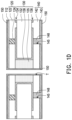
- FIGS. 5 A to 5 B are schematic cross-sectional views of partial steps of a manufacturing method of another circuit board according to another embodiment of the disclosure.
- FIGS. 6 A to 6 B are schematic cross-sectional views of partial steps of a manufacturing method of another circuit board according to another embodiment of the disclosure.
- FIG. 7 is a schematic cross-sectional view of an electronic device according to an embodiment of the disclosure.
- FIG. 8 is a schematic cross-sectional view of an electronic device according to another embodiment of the disclosure.
- FIGS. 1 A to 1 E are schematic cross-sectional views of a manufacturing method of a circuit board according to an embodiment of the disclosure.
- FIG. 1 F is a schematic top view of the circuit board of FIG. 1 E .
- a metal layer 112 a metal layer 112 , a first substrate 120 , a second substrate 130 , and a third substrate 140 are provided.
- the first substrate 120 includes a base 122 and multiple conductive pillars 124 penetrating the base 122 .
- Providing the first substrate 120 includes the following steps. First, the base 122 is provided, and the base 122 is in a B-stage state at this time, which means that the base 122 has not been completely cured. Then, a release film may be attached to two opposite sides of the base 122 , and a material of the release film is, for example, polyester polymer (PET). Afterwards, a drilling process is performed on the base 122 to form a through hole. The drilling process is, for example, laser drilling or mechanical drilling, but the disclosure is not limited thereto.
- PET polyester polymer
- a conductive adhesive is stuffed in the through hole by printing or injection to form the conductive pillars 124 .
- the release film attached to the two opposite sides of the base 122 are removed, so that two opposite surfaces of the conductive pillars 124 respectively protrude from two opposite surfaces of the base 122 , to complete the manufacture of the first base 120 .
- the second substrate 130 includes a core layer 132 , a first circuit layer 134 , a first dielectric layer 135 , a second circuit layer 136 , and a conductive connection layer 138 .
- the core layer 132 has an opening 133 .
- the opening 133 penetrates the second substrate 130 , and the first dielectric layer 135 fills the opening 133 .
- two opposite sides of the first dielectric layer 135 are substantially flush with two opposite ends of the opening 133 .
- the first circuit layer 134 and the second circuit layer 136 are respectively disposed on two opposite sides of the core layer 132 .
- the conductive connection layer 138 covers an inner wall of the opening 133 , and is located between the first dielectric layer 135 and the core layer 132 .
- the conductive connection layer 138 electrically connects the first circuit layer 134 and the second circuit layer 136 .
- the third substrate 140 includes an insulating layer 142 and a conductive layer 143 located on the insulating layer 142 .
- the first substrate 120 and the second substrate 130 are located between the metal layer 112 and the third substrate 140 .
- the first substrate 120 is located between the metal layer 112 and the second substrate 130
- the second substrate 130 is located between the first substrate 120 and the third substrate 140 .
- a thermal lamination process is performed to laminate the metal layer 112 , the first substrate 120 , the second substrate 130 , and the third substrate 140 , so that the metal layer 112 directly covers the base 122 of the first substrate 120 and one side of the conductive pillars 124 .
- the base 122 of the first substrate 120 changes from the original B-stage state to a C-stage state, which means that the base 122 of the first substrate 120 is in a completely cured state, so that the metal layer 112 and the second substrate 130 are respectively connected to the first substrate 120 .
- the conductive pillars 124 of the first substrate 120 are deformed by leaning against the metal layer 112 and the first circuit layer 134 , and the conductive pillars 124 electrically connect the metal layer 112 and the first circuit layer 134 of the second substrate 130 .
- the base 122 of the first substrate 120 covers the core layer 132 , the first circuit layer 134 , and the first dielectric layer 135 of the second substrate 130 .
- the insulating layer 142 of the third substrate 140 is connected to the second circuit layer 136 and covers the core layer 132 , the first dielectric layer 135 , and the second circuit layer 136 of the second substrate 130 .
- multiple blind holes 145 and a through hole T are formed.
- the blind holes 145 extend from the third substrate 140 to the second substrate 130 , and expose the second circuit layer 136 .
- the through hole T penetrates the metal layer 112 , the first substrate 120 , the first dielectric layer 135 of the second substrate 130 , and the insulating layer 142 and the conductive layer 143 of the third substrate 140 .
- a method of forming the blind holes 145 is, for example, laser drilling, and a method of forming the through hole T is, for example, mechanical drilling.
- the disclosure is not limited thereto.
- a conductive material layer 150 is formed, which covers the metal layer 112 , the conductive layer 143 of the third substrate 140 , and an inner wall of the through hole T, and fills the blind holes 145 to define multiple conductive holes 148 .
- a method of forming the conductive material layer 150 is, for example, plating, and the conductive material layer 150 is, for example, copper.
- the disclosure is not limited thereto.
- the conductive material layer 150 , the metal layer 112 , and the conductive layer 143 are patterned through a lithography process to form a first external circuit layer 110 a located on the first substrate 120 and electrically connected to the conductive pillars 124 and a second external circuit layer 144 a located on the insulating layer 142 and electrically connected to the conductive holes 148 , and define a conductive through hole structure 160 a connecting the first external circuit layer 110 a and the second external circuit layer 144 a and located in the through hole T.
- the conductive through hole structure 160 a electrically connects the first external circuit layer 110 a and the second external circuit layer 144 a to define a signal path L 1 .
- the first external circuit layer 110 a , the conductive pillars 124 , the second substrate 130 , the conductive holes 148 , and the second external circuit layer 144 a are electrically connected to define a ground path L 2 .
- the ground path L 2 surrounds the signal path L 1 , and two sides of the signal path L 1 and two sides of the ground path L 2 are respectively located on the same plane. So far, the manufacture of a circuit board 100 a has been completed.
- the circuit board 100 a includes the first external circuit layer 110 a , the first substrate 120 , the second substrate 130 , the third substrate 140 , and the conductive through hole structure 160 a .
- the first substrate 120 is disposed between the first external circuit layer 110 a and the second substrate 130 .
- the first substrate 120 includes the conductive pillars 124 , and the conductive pillars 124 electrically connects the first external circuit layer 110 a and the second substrate 130 .
- the second substrate 130 has the opening 133 and includes the first dielectric layer 135 .
- the opening 133 penetrates the second substrate 130 , and the first dielectric layer 135 fills the opening 133 .
- the second substrate 130 is disposed between the first substrate 120 and the third substrate 140 .
- the third substrate 140 includes the insulating layer 142 , the second external circuit layer 144 a located on the insulating layer 142 , and the conductive holes 148 penetrating the insulating layer 142 and electrically connecting the second substrate 130 and the second external circuit layer 144 a .
- the conductive through hole structure 160 a includes the through hole T and the conductive material layer 150 . The through hole T penetrates the first substrate 120 , the first dielectric layer 135 of the second substrate 130 , and the third substrate 140 .
- the conductive material layer 150 covers the inner wall of the through hole T and electrically connects the first external circuit layer 110 a and the second external circuit layer 144 a to define the signal path L 1 .
- the first external circuit layer 110 a , the conductive pillars 124 , the second substrate 130 , the conductive holes 148 , and the second external circuit layer 144 a are electrically connected to define the ground path L 2 .
- the ground path L 2 surrounds the signal path L 1 .
- the first substrate 120 further includes the base 122 , and the conductive pillars 124 penetrate the base 122 .
- the second substrate 130 further includes the core layer 132 , the first circuit layer 134 , the second circuit layer 136 , and the conductive connection layer 138 .
- the first circuit layer 134 and the second circuit layer 136 are respectively disposed on the two opposite sides of the core layer 132 .
- the core layer 132 has the opening 133
- the conductive connection layer 138 is disposed on the inner wall of the opening 133 and located between the first dielectric layer 135 and the core layer 132 .
- the conductive connection layer 138 electrically connects the first circuit layer 134 and the second circuit layer 136 .
- the conductive pillars 124 electrically connect the first external circuit layer 110 a and the first circuit layer 134 .
- the first external circuit layer 110 a in this embodiment includes a first signal trace 114 a 1 and a first ground trace 114 a 2 .
- the second external circuit layer 144 a includes a second signal trace 144 a 1 and a second ground trace 144 a 2 .
- the first signal trace 114 a 1 , the conductive material layer 150 , and the second signal trace 144 a 1 define the signal path L 1 .
- the first ground trace 114 a 2 , the conductive pillars 124 , the first circuit layer 134 , the conductive connection layer 138 , the second circuit layer 136 , the conductive holes 148 , and the second ground trace 144 a 2 define the ground path L 2 .
- the signal path L 1 Since the signal path L 1 is surrounded by the ground path L 2 and is enclosed in a closed manner, the signal path L 1 may form a good high-frequency and high-speed loop. In addition, the two sides of the signal path L 1 and the two sides of the ground path L 2 are respectively located on the same plane. Since the circuit board 100 a in this embodiment is provided with the conductive pillars 124 and the conductive holes 148 , a shielding gap may be filled to form a complete shield, which may effectively reduce the signal energy loss and reduce the noise interference. As a result, the reliability of signal transmission may be improved.
- the signal path L 1 defined by the first signal trace 114 a 1 , the conductive material layer 150 , and the second signal trace 144 a 1 is surrounded by the ground path L 2 defined by the first ground trace 114 a 2 , the conductive pillars 124 , the first circuit layer 134 , the conductive connection layer 138 , the second circuit layer 136 , the conductive holes 148 , and the second ground trace 144 a 2 .
- the ground path L 2 with a good closure property is disposed around the signal path L 1 that may transmit a high-frequency and high-speed signal such as 5G.
- the good high-frequency and high-speed loop may be formed, so that the circuit board 100 a in this embodiment may have better signal integrity.
- the high frequency refers to a frequency greater than 1 GHz; and the high speed refers to a data transmission speed greater than 100 Mbps.
- first substrate 120 and the second substrate 130 provided in this embodiment are finished products of the circuit boards, while the metal layer 112 and the third substrate 140 are semi-finished products, and the metal layer 112 , the first substrate 120 , the second substrate 130 , and the third substrate 140 are integrated by laminating.
- the conductive through hole structure 160 a, the conductive connection layer 138 of the second substrate 130 , and the first dielectric layer 135 define a coaxial via.
- the first dielectric layer 135 is located between the conductive through hole structure 160 a and the conductive connection layer 138 .
- a manufacturing method of the circuit board 100 a in this embodiment may avoid an impedance mismatch that affects the integrity of the high-frequency signal.
- the manufacturing method of the circuit board 100 a in this embodiment may not only overcome an energy loss of the conductive holes, but also avoid an issue of poor reliability of thermal stress of the stacking holes.
- FIGS. 2 A to 2 B are schematic cross-sectional views of partial steps of a manufacturing method of another circuit board according to another embodiment of the disclosure.
- the manufacturing method of the circuit board in this embodiment is similar to that of the above circuit board.
- a difference between the two is that after forming the conductive material layer 150 in FIG. 1 D , referring to FIG. 2 A , a plugging process is performed to stuff a second dielectric layer 162 in the through hole T, and the second dielectric layer 162 fills the through hole T.
- a first surface 163 and a second surface 165 of the second dielectric layer 162 opposite to each other are respectively flush with an upper surface Si and a lower surface S 2 of the conductive material layer 150 .
- the first surface 163 and the second surface 165 of the second dielectric layer 162 may be respectively flush with the conductive material by selectively grinding, thereby maintaining better flatness.
- a material of the second dielectric layer 162 is, for example, resin, which may be regarded as a plugging agent.
- the lithography process is performed to pattern the conductive material layer 150 , the metal layer 112 , and the conductive layer 143 , so as to form a first external circuit layer 110 b and a second external circuit layer 144 b.
- the first external circuit layer 110 b is located on the base 122 of the first substrate 120
- the second external circuit layer 144 a is located on the insulating layer 142 of a third substrate 140 b.
- a conductive through hole structure 160 b includes the through hole T, the conductive material layer 150 , and the second dielectric layer 162 located in the through hole T. So far, the manufacture of a circuit board 100 b has been completed.
- FIGS. 3 A to 3 B are schematic cross-sectional views of partial steps of a manufacturing method of another circuit board according to another embodiment of the disclosure.
- the manufacturing method of the circuit board in this embodiment is similar to that of the above circuit board.
- a difference between the two is that after stuffing the second dielectric layer 162 in the through hole T in FIG. 2 A , referring to FIG. 3 A , a capping layer 155 is formed on the conductive material layer 150 .
- the capping layer 155 covers the conductive material layer 150 , and the first surface 163 and the second surface 165 of the second dielectric layer 162 .
- a material of the capping layer 155 is, for example, copper, but the disclosure is not limited thereto.
- the lithography process is performed to pattern the capping layer 155 , the conductive material layer 150 , the metal layer 112 , and the conductive layer 143 , so as to form a first external circuit layer 110 c and a second external circuit layer 144 c.
- the first external circuit layer 110 c is located on the base 122 of the first substrate 120 and on the first surface 163 of the second dielectric layer 162 .
- the second external circuit layer 144 c is located on the insulating layer 142 of a third substrate 140 c and on the second surface 165 of the second dielectric layer 162 . So far, the manufacture of a circuit board 100 c has been completed.
- FIGS. 4 A to 4 E are schematic cross-sectional views of a manufacturing method of another circuit board according to another embodiment of the disclosure. Referring to both FIGS. 1 A and 4 A , the manufacturing method of the circuit board in this embodiment is similar to that of the above circuit board. A difference between the two is that a first substrate 120 d in this embodiment is different from the first substrate 120 .
- the first substrate 120 d in this embodiment further includes a dielectric material bulk 126 penetrating the base 122 .
- the dielectric material bulk 126 is located between the conductive pillars 124 , and a peripheral surface of the dielectric material bulk 126 directly contacts the conductive pillars 124 .
- the base 122 is provided.
- the base 122 is in the B-stage state at this time, which means that the base 122 has not been completely cured.
- a material of the base 122 is, for example, epoxy, PTFE, polyphenylene ether (PPE), polyimide (PI), BT (bismaleimide triazine) resin, phenolic novolac (PN) resin, and hydrocarbon.
- the release film may be attached to the two opposite sides of the base 122 , and the material of the release film is, for example, polyester polymer (PET).
- PET polyester polymer
- the drilling process is performed on the base 122 to form the through hole and the opening.
- the drilling process is, for example, laser drilling or mechanical punching, but the disclosure is not limited thereto.
- the conductive adhesive is stuffed in the through hole by printing or injection to form the conductive pillars 124 .
- a dielectric material with a low dielectric constant (Dk) and a low dissipation factor (Df) are printed in the opening and pre-baked to form the dielectric material bulk 126 .
- a dissipation factor of the dielectric material bulk 126 is between 0.0002 and 0.006.
- a high-frequency circuit emphasizes the speed and quality of a transmission signal, and a main factor affecting the two is an electrical characteristic of a transmission material, that is, the dielectric constant (Dk) and the dissipation factor (Df) of the material.
- Dk dielectric constant
- Df dissipation factor
- the thermal lamination process is performed to laminate the metal layer 112 , the first substrate 120 d, the second substrate 130 , and the third substrate 140 , so that the metal layer 112 directly covers the base 122 of the first substrate 120 d, one side of the conductive pillars 124 , and a surface 126 a of the dielectric material bulk 126 .
- the conductive pillars 124 connect the metal layer 112 and the first circuit layer 134 of the second substrate 130 .
- An another surface 126 b of the dielectric material bulk 126 directly contacts the first dielectric layer 135 and the first circuit layer 134 of the second substrate 130 .
- the insulating layer 142 of the third substrate 140 is connected to the second circuit layer 136 of the second substrate 130 , and covers the core layer 132 , the first dielectric layer 135 , and the second circuit layer 136 .
- the blind holes 145 and a through hole T′ are formed.
- the blind holes 145 extend from the third substrate 140 to the second substrate 130 , and expose the second circuit layer 136 .
- the through hole T′ penetrates the metal layer 112 , the dielectric material bulk 126 of the first substrate 120 d , the first dielectric layer 135 of the second substrate 130 , and the insulating layer 142 and the conductive layer 143 of the third substrate 140 .
- the method of forming the blind holes 145 is, for example, laser drilling, and a method of forming the through hole T′ is, for example, mechanical drilling.
- the disclosure is not limited thereto.
- a conductive material layer 150 ′ is formed, which covers the metal layer 112 , the conductive layer 143 of the third substrate 140 , and an inner wall of the through hole T′, and fills the blind holes 145 to define multiple conductive holes 148 ′.
- a method of forming the conductive material layer 150 ′ is, for example, plating, and the conductive material layer 150 ′ is, for example, copper.
- the disclosure is not limited thereto.
- the conductive material layer 150 ′, the metal layer 112 , and the conductive layer 143 are patterned through the lithography process to form a first external circuit layer 110 d located on the first substrate 120 d and electrically connected to the conductive pillars 124 and a second external circuit layer 144 d located on the insulating layer 142 and electrically connected to the conductive holes 148 ′, and define a conductive through hole structure 160 d connecting the first external circuit layer 110 d and the second external circuit layer 144 d and located in the through hole T′.
- the conductive through hole structure 160 d electrically connects the first external circuit layer 110 d and the second external circuit layer 144 d to define a signal path L 1 ′.
- the first external circuit layer 110 d , the conductive pillars 124 , the second substrate 130 , the conductive holes 148 ′, and the second external circuit layer 144 d are electrically connected to define a ground path L 2 ′.
- the ground path L 2 ′ surrounds the signal path L 1 ′, and two sides of the signal path L 1 ′ and two sides of the ground path L 2 ′ are respectively located on the same plane. So far, the manufacture of a circuit board 100 d has been completed.
- the circuit board 100 d in this embodiment is similar to the circuit board 100 a .
- the first substrate 120 d further includes the dielectric material bulk 126 , which penetrates the base 122 and is located between the conductive pillars 124 .
- the peripheral surface of the dielectric material bulk 126 directly contacts the conductive pillars 124 .
- the first external circuit layer 110 d in this embodiment includes a first signal trace 114 d 1 and a first ground trace 114 d 2 .
- the second external circuit layer 144 d includes a second signal trace 144 d 1 and a second ground trace 144 d 2 .
- the first signal trace 114 d 1 , the conductive material layer 150 ′, and the second signal trace 144 d 1 define the signal path L 1 ′.
- the first ground trace 114 d 2 , the conductive pillars 124 , the first circuit layer 134 , the conductive connection layer 138 , the second circuit layer 136 , the conductive holes 148 ′, and the second ground trace 144 d 2 define the ground path L 2 ′.
- the signal path L 1 ′ defined by the first signal trace 114 d 1 , the conductive material layer 150 ′, and the second signal trace 144 d 1 is surrounded by the ground path L 2 ′ defined by the first ground trace 114 d 2 , the conductive pillars 124 , the first circuit layer 134 , the conductive connection layer 138 , the second circuit layer 136 , the conductive holes 148 ′, and the second ground trace 144 d 2 .
- the ground path L 2 ′ with a good closure property is disposed around the signal path L 1 ′ that may transmit the high-frequency and high-speed signal such as 5G. In this way, the good high-frequency and high-speed loop may be formed, so that the circuit board 100 d in this embodiment may have better signal integrity.
- FIGS. 5 A to 5 B are schematic cross-sectional views of partial steps of a manufacturing method of another circuit board according to another embodiment of the disclosure.
- the manufacturing method of the circuit board in this embodiment is similar to that of the above circuit board.
- a difference between the two is that after forming the conductive material layer 150 ′ in FIG. 4 D , referring to FIG. 5 A , the plugging process is performed to stuff the second dielectric layer 162 in the through hole T′, and the second dielectric layer 162 fills the through hole T′.
- the first surface 163 and the second surface 165 of the second dielectric layer 162 opposite to each other are respectively flush with an upper surface S 1 ′ and a lower surface S 2 ′ of the conductive material layer 150 ′.
- the second dielectric layer 162 is higher than the upper surface S 1 ′ and the lower surface S 2 ′ of the conductive material layer 150 ′, the first surface 163 and the second surface 165 of the second dielectric layer 162 are respectively flush with the conductive material layer 150 ′ by selectively grinding.
- the material of the second dielectric layer 162 is, for example, resin, which may be regarded as the plugging agent.
- the lithography process is performed to pattern the conductive material layer 150 ′, the metal layer 112 , and the conductive layer 143 , so as to form a first external circuit layer 110 e and a second external circuit layer 144 e.
- the first external circuit layer 110 e is located on the base 122 of the first substrate 120 d
- the second external circuit layer 144 e is located on the insulating layer 142 of a third substrate 140 e.
- a conductive through hole structure 160 e includes the through hole T′, the conductive material layer 150 ′, and the second dielectric layer 162 located in the through hole T′. So far, the manufacture of a circuit board 100 e has been completed.
- FIGS. 6 A to 6 B are schematic cross-sectional views of partial steps of a manufacturing method of another circuit board according to another embodiment of the disclosure.
- the manufacturing method of the circuit board in this embodiment is similar to that of the above circuit board.
- a difference between the two is that after stuffing the second dielectric layer 162 in the through hole T′ in FIG. 5 A , referring to FIG. 6 A , a capping layer 155 ′ is formed on the conductive material layer 150 ′.
- the capping layer 155 ′ covers the conductive material layer 150 ′, and the first surface 163 and the second surface 165 of the second dielectric layer 162 .
- a material of the capping layer 155 ′ is, for example, copper, but the disclosure is not limited thereto.
- the lithography process is performed to pattern capping layer 155 ′, the conductive material layer 150 ′, the metal layer 112 , and the conductive layer 143 , so as to form a first external circuit layer 110 f and a second external circuit layer 144 f .
- the first external circuit layer 110 f is located on the base 122 of the first substrate 120 d and on the first surface 163 of the second dielectric layer 162 .
- the second external circuit layer 144 f is located on the insulating layer 142 of the third substrate 140 f and on the second surface 165 of the second dielectric layer 162 . So far, the manufacture of a circuit board 100 f has been completed.
- FIG. 7 is a schematic cross-sectional view of an electronic device according to an embodiment of the disclosure.
- an electronic device 10 a includes, for example, the circuit board 100 c as shown in FIG. 3 B and an electronic element 200 .
- the electronic element 200 is electrically connected to the circuit board 100 c, and the electronic element 200 includes multiple pads 210 .
- the electronic device 10 a in this embodiment further includes multiple connecting members 300 , which are disposed between the third substrate 140 c of the circuit board 100 c and the electronic element 200 .
- the electronic element 200 is electrically connected to the circuit board 100 c through the connecting members 300 .
- the connecting members 300 are, for example, multiple solder balls, but the disclosure is not limited thereto.
- an antenna structure may be disposed on the other side of the circuit board 100 c relative to the electronic element 200 , and the antenna structure may be electrically connected to the circuit board 100 c .
- the circuit board 100 c in this embodiment may solve an issue of signal interference on the same plane, reduce the signal energy loss, and reduce the noise interference. As a result, the reliability of signal transmission may be improved.
- FIG. 8 is a schematic cross-sectional view of an electronic device according to another embodiment of the disclosure.
- an electronic device 10 b includes, for example, the circuit board 100 f as shown in FIG. 6 B and the electronic element 200 .
- the electronic element 200 is electrically connected to the circuit board 100 f
- the electronic element 200 includes the pads 210 .
- the electronic device 10 b in this embodiment further includes the connecting members 300 , which are disposed between the third substrate 140 f of the circuit board 100 f and the electronic element 200 .
- the electronic element 200 is electrically connected to the circuit board 100 f through the connecting members 300 .
- the connecting members 300 are, for example, the solder balls, but the disclosure is not limited thereto.
- the antenna structure may be disposed on the other side of the circuit board 100 f relative to the electronic element 200 , and the antenna structure may be electrically connected to the circuit board 100 f.
- the circuit board 100 f in this embodiment may solve the issue of signal interference on the same plane, reduce the signal energy loss, and reduce the noise interference. As a result, the reliability of signal transmission may be improved.
- the conductive aterial layer of the conductive through hole structure electrically connects the first external circuit layer and the second external circuit layer to define the signal path
- the first external circuit layer, the conductive pillars, the second substrate, the conductive holes, and the second external circuit layer are electrically connected to define the ground path.
- the ground path surrounds the signal path.
Landscapes
- Engineering & Computer Science (AREA)
- Microelectronics & Electronic Packaging (AREA)
- Manufacturing & Machinery (AREA)
- Physics & Mathematics (AREA)
- Electromagnetism (AREA)
- Printing Elements For Providing Electric Connections Between Printed Circuits (AREA)
Abstract
Description
Claims (9)
Priority Applications (6)
| Application Number | Priority Date | Filing Date | Title |
|---|---|---|---|
| US17/498,757 US12057381B2 (en) | 2021-01-21 | 2021-10-12 | Circuit board having laminated build-up layers |
| CN202210164117.8A CN115708396A (en) | 2021-08-19 | 2022-02-22 | Circuit board, manufacturing method thereof and electronic device |
| TW111106293A TWI835074B (en) | 2021-08-19 | 2022-02-22 | Circuit board and manufacturing method thereof and electronic device |
| US17/711,027 US12177964B2 (en) | 2021-01-21 | 2022-04-01 | Circuit board and manufacturing method thereof and electronic device |
| US18/650,005 US20240282687A1 (en) | 2021-01-21 | 2024-04-29 | Manufacturing method of circuit board |
| US18/930,988 US20250056712A1 (en) | 2021-01-21 | 2024-10-29 | Manufacturing method of circuit board |
Applications Claiming Priority (5)
| Application Number | Priority Date | Filing Date | Title |
|---|---|---|---|
| US202163139795P | 2021-01-21 | 2021-01-21 | |
| US202163235105P | 2021-08-19 | 2021-08-19 | |
| TW110134179A TWI777768B (en) | 2021-01-21 | 2021-09-14 | Circuit board and manufacturing method thereof and electronic device |
| TW110134179 | 2021-09-14 | ||
| US17/498,757 US12057381B2 (en) | 2021-01-21 | 2021-10-12 | Circuit board having laminated build-up layers |
Related Child Applications (2)
| Application Number | Title | Priority Date | Filing Date |
|---|---|---|---|
| US17/711,027 Continuation-In-Part US12177964B2 (en) | 2021-01-21 | 2022-04-01 | Circuit board and manufacturing method thereof and electronic device |
| US18/650,005 Division US20240282687A1 (en) | 2021-01-21 | 2024-04-29 | Manufacturing method of circuit board |
Publications (2)
| Publication Number | Publication Date |
|---|---|
| US20220230949A1 US20220230949A1 (en) | 2022-07-21 |
| US12057381B2 true US12057381B2 (en) | 2024-08-06 |
Family
ID=82405334
Family Applications (2)
| Application Number | Title | Priority Date | Filing Date |
|---|---|---|---|
| US17/498,757 Active 2042-11-12 US12057381B2 (en) | 2021-01-21 | 2021-10-12 | Circuit board having laminated build-up layers |
| US18/650,005 Pending US20240282687A1 (en) | 2021-01-21 | 2024-04-29 | Manufacturing method of circuit board |
Family Applications After (1)
| Application Number | Title | Priority Date | Filing Date |
|---|---|---|---|
| US18/650,005 Pending US20240282687A1 (en) | 2021-01-21 | 2024-04-29 | Manufacturing method of circuit board |
Country Status (1)
| Country | Link |
|---|---|
| US (2) | US12057381B2 (en) |
Families Citing this family (3)
| Publication number | Priority date | Publication date | Assignee | Title |
|---|---|---|---|---|
| CN115966511B (en) * | 2022-12-05 | 2025-10-14 | 武汉新芯集成电路股份有限公司 | Semiconductor device and method for manufacturing the same |
| CN219627975U (en) * | 2023-02-28 | 2023-09-01 | 瑞声光电科技(常州)有限公司 | Flexible circuit board |
| CN119342680B (en) * | 2023-07-20 | 2025-10-28 | 宏启胜精密电子(秦皇岛)有限公司 | Flexible circuit board and manufacturing method thereof |
Citations (7)
| Publication number | Priority date | Publication date | Assignee | Title |
|---|---|---|---|---|
| US20080218985A1 (en) * | 2007-03-07 | 2008-09-11 | Tsutomu Takeda | Multilayer printed circuit board and method of manufacturing same |
| US20110203842A1 (en) | 2010-02-25 | 2011-08-25 | Russell James V | Method and structure for coaxial via routing in printed circuit boards for improved signal integrity |
| US20130098669A1 (en) | 2011-10-21 | 2013-04-25 | Fujitsu Limited | Wiring substrate and manufacturing method for wiring substrate |
| US20150014045A1 (en) | 2013-07-15 | 2015-01-15 | Massachusetts Institute Of Technology | Sleeved Coaxial Printed Circuit Board Vias |
| US20180184522A1 (en) * | 2016-12-28 | 2018-06-28 | Intel Corporation | Internal to internal coaxial via transition structures in package substrates |
| TW201918134A (en) | 2017-10-20 | 2019-05-01 | 南韓商三星電機股份有限公司 | Printed circuit board |
| TW201933562A (en) | 2018-01-29 | 2019-08-16 | 巴貝多商馬維爾世界貿易股份有限公司 | Coaxial interconnect structure of semiconductor components |
-
2021
- 2021-10-12 US US17/498,757 patent/US12057381B2/en active Active
-
2024
- 2024-04-29 US US18/650,005 patent/US20240282687A1/en active Pending
Patent Citations (8)
| Publication number | Priority date | Publication date | Assignee | Title |
|---|---|---|---|---|
| US20080218985A1 (en) * | 2007-03-07 | 2008-09-11 | Tsutomu Takeda | Multilayer printed circuit board and method of manufacturing same |
| US20110203842A1 (en) | 2010-02-25 | 2011-08-25 | Russell James V | Method and structure for coaxial via routing in printed circuit boards for improved signal integrity |
| TW201220967A (en) | 2010-02-25 | 2012-05-16 | R & Amp D Circuits Inc | Method and structure for coaxial via routing in printed circuit boards for improved signal integrity |
| US20130098669A1 (en) | 2011-10-21 | 2013-04-25 | Fujitsu Limited | Wiring substrate and manufacturing method for wiring substrate |
| US20150014045A1 (en) | 2013-07-15 | 2015-01-15 | Massachusetts Institute Of Technology | Sleeved Coaxial Printed Circuit Board Vias |
| US20180184522A1 (en) * | 2016-12-28 | 2018-06-28 | Intel Corporation | Internal to internal coaxial via transition structures in package substrates |
| TW201918134A (en) | 2017-10-20 | 2019-05-01 | 南韓商三星電機股份有限公司 | Printed circuit board |
| TW201933562A (en) | 2018-01-29 | 2019-08-16 | 巴貝多商馬維爾世界貿易股份有限公司 | Coaxial interconnect structure of semiconductor components |
Non-Patent Citations (2)
| Title |
|---|
| "Office Action of Taiwan Related Application, Application No. 111106293", issued on May 19, 2023, p. 1-p. 12. |
| "Office Action of U.S. Appl. No. 17/711,027", issued on May 23, 2024, p. 1-p. 17. |
Also Published As
| Publication number | Publication date |
|---|---|
| US20220230949A1 (en) | 2022-07-21 |
| US20240282687A1 (en) | 2024-08-22 |
Similar Documents
| Publication | Publication Date | Title |
|---|---|---|
| US20240282687A1 (en) | Manufacturing method of circuit board | |
| US11057996B2 (en) | Circuit board, method of manufacturing circuit board, and electronic device | |
| TWI835074B (en) | Circuit board and manufacturing method thereof and electronic device | |
| US9331030B1 (en) | Integrated antenna package and manufacturing method thereof | |
| US8633395B2 (en) | Multilayer wiring board | |
| CN108966478B (en) | Flexible circuit board and manufacturing method thereof | |
| US20120292085A1 (en) | Flexible printed circuit and method of manufacturing the same | |
| US20100308941A1 (en) | High-frequency line structure on resin substrate and method of manufacturing the same | |
| JP2017215197A (en) | Radio-frequency substrate | |
| CN114828384B (en) | Circuit board, manufacturing method thereof and electronic device | |
| US20250056712A1 (en) | Manufacturing method of circuit board | |
| US12052815B2 (en) | Manufacturing method of circuit board | |
| US11564313B2 (en) | Wiring body and method for manufacturing same | |
| CN114128410B (en) | High-frequency transmission circuit board and manufacturing method thereof | |
| CN115776760B (en) | Circuit board, manufacturing method thereof and electronic device | |
| CN114828385B (en) | Circuit board and manufacturing method thereof and electronic device | |
| US11737209B2 (en) | Circuit board and manufacturing method thereof and electronic device | |
| US12563668B2 (en) | Circuit board, manufacturing method thereof, and electronic device | |
| CN115411510A (en) | Manufacturing method of antenna package and antenna package | |
| US12144113B2 (en) | Circuit board structure | |
| US11737206B2 (en) | Circuit board structure | |
| KR102186150B1 (en) | Printed circuit board using the insulating film and method for manufacturing the same | |
| JP7449655B2 (en) | multilayer printed wiring board | |
| Areias et al. | Additively Manufactured 3-D Printed Shielded Interconnects for Enhanced Immunity to EMI | |
| CN114449736A (en) | High-frequency circuit board and manufacturing method thereof |
Legal Events
| Date | Code | Title | Description |
|---|---|---|---|
| FEPP | Fee payment procedure |
Free format text: ENTITY STATUS SET TO UNDISCOUNTED (ORIGINAL EVENT CODE: BIG.); ENTITY STATUS OF PATENT OWNER: LARGE ENTITY |
|
| AS | Assignment |
Owner name: UNIMICRON TECHNOLOGY CORP., TAIWAN Free format text: ASSIGNMENT OF ASSIGNORS INTEREST;ASSIGNORS:LU, CHIH-CHIANG;LIU, HSIN-NING;HUANG, JUN-RUI;AND OTHERS;SIGNING DATES FROM 20211001 TO 20211011;REEL/FRAME:057840/0597 |
|
| STPP | Information on status: patent application and granting procedure in general |
Free format text: DOCKETED NEW CASE - READY FOR EXAMINATION |
|
| STPP | Information on status: patent application and granting procedure in general |
Free format text: NON FINAL ACTION MAILED |
|
| STPP | Information on status: patent application and granting procedure in general |
Free format text: RESPONSE TO NON-FINAL OFFICE ACTION ENTERED AND FORWARDED TO EXAMINER |
|
| STPP | Information on status: patent application and granting procedure in general |
Free format text: NOTICE OF ALLOWANCE MAILED -- APPLICATION RECEIVED IN OFFICE OF PUBLICATIONS |
|
| ZAAA | Notice of allowance and fees due |
Free format text: ORIGINAL CODE: NOA |
|
| ZAAB | Notice of allowance mailed |
Free format text: ORIGINAL CODE: MN/=. |
|
| STPP | Information on status: patent application and granting procedure in general |
Free format text: AWAITING TC RESP., ISSUE FEE NOT PAID |
|
| STPP | Information on status: patent application and granting procedure in general |
Free format text: AWAITING TC RESP, ISSUE FEE PAYMENT VERIFIED |
|
| STCF | Information on status: patent grant |
Free format text: PATENTED CASE |