US12042850B2 - Detection and removal of continuous caster-related defects on slabs - Google Patents
Detection and removal of continuous caster-related defects on slabs Download PDFInfo
- Publication number
- US12042850B2 US12042850B2 US17/186,239 US202117186239A US12042850B2 US 12042850 B2 US12042850 B2 US 12042850B2 US 202117186239 A US202117186239 A US 202117186239A US 12042850 B2 US12042850 B2 US 12042850B2
- Authority
- US
- United States
- Prior art keywords
- defect
- cast metal
- remediation
- detection
- signal
- Prior art date
- Legal status (The legal status is an assumption and is not a legal conclusion. Google has not performed a legal analysis and makes no representation as to the accuracy of the status listed.)
- Active, expires
Links
- 230000007547 defect Effects 0.000 title claims abstract description 166
- 238000001514 detection method Methods 0.000 title claims abstract description 118
- 239000002184 metal Substances 0.000 claims abstract description 152
- 229910052751 metal Inorganic materials 0.000 claims abstract description 152
- 238000005067 remediation Methods 0.000 claims abstract description 79
- 238000009749 continuous casting Methods 0.000 claims abstract description 17
- 238000000034 method Methods 0.000 claims description 32
- 238000002844 melting Methods 0.000 claims description 9
- 230000008018 melting Effects 0.000 claims description 9
- 238000000227 grinding Methods 0.000 claims description 8
- 238000002679 ablation Methods 0.000 claims description 7
- 230000008878 coupling Effects 0.000 claims description 5
- 238000010168 coupling process Methods 0.000 claims description 5
- 238000005859 coupling reaction Methods 0.000 claims description 5
- 229910000831 Steel Inorganic materials 0.000 claims description 4
- 239000010959 steel Substances 0.000 claims description 4
- 239000000463 material Substances 0.000 description 7
- 238000012360 testing method Methods 0.000 description 3
- 238000010521 absorption reaction Methods 0.000 description 2
- 230000002238 attenuated effect Effects 0.000 description 2
- 239000011248 coating agent Substances 0.000 description 2
- 238000000576 coating method Methods 0.000 description 2
- 238000003475 lamination Methods 0.000 description 2
- 239000003607 modifier Substances 0.000 description 2
- 230000000717 retained effect Effects 0.000 description 2
- 238000005096 rolling process Methods 0.000 description 2
- 230000001052 transient effect Effects 0.000 description 2
- 230000003321 amplification Effects 0.000 description 1
- 230000005674 electromagnetic induction Effects 0.000 description 1
- 238000009499 grossing Methods 0.000 description 1
- 238000013101 initial test Methods 0.000 description 1
- 230000003993 interaction Effects 0.000 description 1
- 229910001338 liquidmetal Inorganic materials 0.000 description 1
- 150000002739 metals Chemical class 0.000 description 1
- 238000003199 nucleic acid amplification method Methods 0.000 description 1
- 230000003287 optical effect Effects 0.000 description 1
- 239000000843 powder Substances 0.000 description 1
- 238000007493 shaping process Methods 0.000 description 1
- 238000001228 spectrum Methods 0.000 description 1
- 238000002604 ultrasonography Methods 0.000 description 1
Images


Classifications
-
- B—PERFORMING OPERATIONS; TRANSPORTING
- B22—CASTING; POWDER METALLURGY
- B22D—CASTING OF METALS; CASTING OF OTHER SUBSTANCES BY THE SAME PROCESSES OR DEVICES
- B22D11/00—Continuous casting of metals, i.e. casting in indefinite lengths
- B22D11/12—Accessories for subsequent treating or working cast stock in situ
- B22D11/122—Accessories for subsequent treating or working cast stock in situ using magnetic fields
-
- B—PERFORMING OPERATIONS; TRANSPORTING
- B22—CASTING; POWDER METALLURGY
- B22D—CASTING OF METALS; CASTING OF OTHER SUBSTANCES BY THE SAME PROCESSES OR DEVICES
- B22D11/00—Continuous casting of metals, i.e. casting in indefinite lengths
- B22D11/16—Controlling or regulating processes or operations
- B22D11/20—Controlling or regulating processes or operations for removing cast stock
- B22D11/201—Controlling or regulating processes or operations for removing cast stock responsive to molten metal level or slag level
- B22D11/205—Controlling or regulating processes or operations for removing cast stock responsive to molten metal level or slag level by using electric, magnetic, sonic or ultrasonic means
-
- G—PHYSICS
- G01—MEASURING; TESTING
- G01N—INVESTIGATING OR ANALYSING MATERIALS BY DETERMINING THEIR CHEMICAL OR PHYSICAL PROPERTIES
- G01N29/00—Investigating or analysing materials by the use of ultrasonic, sonic or infrasonic waves; Visualisation of the interior of objects by transmitting ultrasonic or sonic waves through the object
- G01N29/04—Analysing solids
- G01N29/043—Analysing solids in the interior, e.g. by shear waves
-
- G—PHYSICS
- G01—MEASURING; TESTING
- G01N—INVESTIGATING OR ANALYSING MATERIALS BY DETERMINING THEIR CHEMICAL OR PHYSICAL PROPERTIES
- G01N29/00—Investigating or analysing materials by the use of ultrasonic, sonic or infrasonic waves; Visualisation of the interior of objects by transmitting ultrasonic or sonic waves through the object
- G01N29/22—Details, e.g. general constructional or apparatus details
- G01N29/24—Probes
- G01N29/2412—Probes using the magnetostrictive properties of the material to be examined, e.g. electromagnetic acoustic transducers [EMAT]
-
- G—PHYSICS
- G01—MEASURING; TESTING
- G01N—INVESTIGATING OR ANALYSING MATERIALS BY DETERMINING THEIR CHEMICAL OR PHYSICAL PROPERTIES
- G01N2291/00—Indexing codes associated with group G01N29/00
- G01N2291/02—Indexing codes associated with the analysed material
- G01N2291/028—Material parameters
- G01N2291/0289—Internal structure, e.g. defects, grain size, texture
-
- G—PHYSICS
- G01—MEASURING; TESTING
- G01N—INVESTIGATING OR ANALYSING MATERIALS BY DETERMINING THEIR CHEMICAL OR PHYSICAL PROPERTIES
- G01N2291/00—Indexing codes associated with group G01N29/00
- G01N2291/04—Wave modes and trajectories
- G01N2291/044—Internal reflections (echoes), e.g. on walls or defects
Definitions
- liquid metal such as steel is solidified into a cast metal that can be cut into a semifinished slab for subsequent finishing (e.g., rolling, coiling, coating, etc.)
- caster-related defects e.g., laminations, cracks, pin holes, etc.
- These near sub-surface defects typically manifest themselves downstream, after the continuous casting process, making such defects difficult to detect and/or remediate. This can result in all or a portion of the cast metal being subjected to surface scarfing and/or rejection, creating additional costs.
- This can decrease the number of near sub-surface caster-related defects in a finished product, which can decrease costs and/or increase efficiency of the continuous casting process.
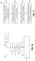
- FIG. 1 is a perspective view of an exemplary defect detection and remediation system for use on continuously cast metal.
- FIG. 2 is a side elevational view of a detection unit of the defect detection and remediation system of FIG. 1 .
- FIG. 3 is a side elevational view of a first exemplary signal generator for use with the detection unit of FIG. 2 .
- FIG. 4 is a side elevational view of a second exemplary signal generator for use with the detection unit of FIG. 2 .
- FIG. 5 is a side elevational view of an exemplary receiver for use with the detection unit of FIG. 2 .
- FIG. 6 is a side elevational view of the detection unit of FIG. 2 , showing a continuously cast metal containing a defect being translated relative to the detection unit.
- FIG. 7 is a top plan view of the detection unit of FIG. 6 .
- FIG. 8 is a side elevational view of the detection unit of FIG. 6 , showing the defect positioned within the detection unit.
- FIG. 9 is a graph showing a signal detected by the detection unit of FIG. 6 .
- FIG. 10 is a side elevational view of a remediation unit of the defect detection and remediation system of FIG. 1 .
- FIG. 11 is a flowchart of an exemplary method of detecting and remediating a defect in a cast metal with the defect detection and remediation system of FIG. 1 .
- FIG. 12 is a graph of a signal received of by a detection unit on a test block of cast metal having a simulated sub-surface defect.
- FIG. 13 is a graph of a signal of raw data received by another detection unit on the test block of cast metal having the simulated sub-surface defect.
- FIG. 14 is a graph of the signal of FIG. 13 that has been modified by a polynomial trend.
- FIG. 15 is a graph of the signal of FIG. 14 that has been modified by a Fast Fourier Transform.
- a defect detection and remediation system can be used to remediate near sub-surface, caster related defects detected within a cast metal during the continuous casting stage, prior to subsequent finishing.
- the system comprises a detection device for detecting whether a defect is present within the cast metal and a remediation device for remediating the defect detected by the detection device in a target area containing the defect.
- the detection device comprises one or more signal generators configured to generate a pulse directed toward the surface of the cast metal to thereby generate one or more ultrasonic waves within the cast metal and one or more receivers spaced a distance away from the one or more signal generators that are configured to receive a signal caused by the one or more ultrasonic waves within the cast metal.
- the system can then detect the presence of the defect based on one or more characteristics (e.g., amplitude, frequency, wavelength, etc.) of the signal received by the receiver.
- the system can then determine whether the detected defect can be remediated, such as based on a size and/or position of the detected defect.
- the remediation device comprises one or more remediation units having a laser configured to generate a beam directed toward the surface of the cast metal in the target area containing the defect.
- the remediation unit can thereby smooth the detected defect by one or more of ablation, melting, grinding, and scarfing in the target area. This spot remediation of detected sub-surface defects in cast metal can reduce the amount of cast metal subjected surface scarfing and/or rejection to thereby improve costs and/or efficiency of the continuous casting process. Because the system is not physically coupled with the cast metal, the system is operable in a high temperature and/or contaminated environment.
- System 10 for use on continuously cast metal 2 such as steel to reduce the number and/or extent of near sub-surface defects 4 within cast metal 2 .
- System 10 comprises a detection device 20 having one or more detection units 22 and a remediation device 30 having one or more remediation units 32 .
- Detection units 22 of detection device 20 are configured to detect defects 4 , such as caster-related defects (e.g., laminations, cracks, pin holes, etc.), at a surface 8 and/or near sub-surface to surface 8 of cast metal 2 .
- detection device 20 can detect one or more defects 4 having a depth of about 10 millimeters or less, such as about 5 millimeters or less.
- remediation units 32 of remediation device 30 are configured to remediate defects 4 detected by detection device 20 by removing and/or improving the number and/or extent of detected defects 4 by forming a remediated area 6 that is more continuous than when the area contained defect 4 .
- remediation device 30 can sufficiently improve and/or remediate a defect 4 at and/or near a surface 8 of cast metal 2 at a desired area of cast metal 2 .
- system 10 is configured to remediate a defect 4 detected on cast metal 2 during the continuous casting stage, such as when the cast metal 2 has retained thermal energy from the continuous casting process, prior to subsequent finishing (e.g., rolling, coiling, coating, etc.).
- System 10 can operate in high temperatures of up to about 1,000° C., such as up to about 700° C. Additionally or alternatively, system 10 can remediate defects 4 on cast metal 2 after cast metal 2 is cooled, prior to subsequent finishing.
- System 10 is further configured to operate while cast metal 2 is translated relative to system 10 , as shown by arrow 40 in FIG. 1 .
- system 10 can be installed at a caster run-out table, where cast metal 2 is cut into slabs such that system 10 can remediate defects before and/or after cast metal 2 is cut into slabs.
- system 10 can operate while cast metal 2 is moved at a speed between about 0.5 meters per second and about 5 meters per second relative to system 10 , though other suitable speeds can be used such that system 10 can sufficiently detect and/or remediate a defect 4 on cast metal 2 .
- remediation units 32 can be spaced in an array and/or movable along remediation device 30 such that remediation units 32 can remediate a defect 4 in a select area of cast metal 2 , such as along a portion or an entire surface 8 of cast metal 2 .
- a distance between detection device 20 and remediation device 30 can be adjusted.
- remediation device 30 is moveable longitudinally along the direction of translation of cast metal 2 relative to detection device 20 such that remediation device 30 is moveable closer to and/or farther from detection device 20 , as shown by arrow 46 .
- This can also allow remediation device 30 to translate with cast metal 2 as remediation device 30 remediates a defect 4 .
- detection device 20 can be movable longitudinally. Still other suitable configurations for system 10 will be apparent to one with ordinary skill in the art in view of the teachings herein.
- detection device 20 and/or remediation device 30 can be water-cooled.
- a detection unit 22 of detection device 20 comprises one or signal generators 24 and one or more receivers 26 .
- Signal generator 24 is configured to generate an ultrasonic pulse 21 that is directed toward a surface 8 of cast metal 2 .
- Signal generator 24 can be coupled with a control 28 such that control 28 can be configured to control pulse 21 of signal generator 24 (e.g., a pulse rate, a pulse energy, a wavelength, frequency, etc.).
- Pulse 21 generated by signal generator 24 is at least partially absorbed by cast metal 2 such that pulse 21 forms one or more ultrasonic waves 23 that travel through cast metal 2 .
- Receiver 26 is spaced away from signal generator 24 at a select distance x and is configured to detect a signal 25 caused by waves 23 .
- Receiver 26 can be coupled with control 28 such that control 28 can be configured to receive signal 25 detected by receiver 26 .
- Control 28 can be configured to analyze characteristics (e.g., a pulse rate, a pulse energy, an amplitude, a wavelength, frequency, etc.) of signal 25 to determine whether a defect is present near surface 8 within cast metal 2 based on signal 25 .
- control 28 can determine whether the characteristics of signal 25 have been altered relative to pulse 21 and/or whether the characteristics fail to meet a predetermined level to determine that a defect is present within cast metal 2 .
- Detection device 20 is thereby configured to detect whether a defect is present below a desired surface 8 of cast metal 2 .
- detection device 20 can further be configured to determine the position and/or size of the detected defect based on the received signal 25 . Because signal generator 24 and receiver 26 are spaced away from surface 8 of cast metal 2 without a physical coupling with cast metal 2 , detection unit 22 is operable at high temperatures and/or in a contaminated environment such as when surface 8 contains residue from the continuous casting process.
- Signal generator 24 can comprise a laser, an electromagnetic acoustic transducer (EMAT), and/or other suitable signal generator that is configured to generate pulse 21 .
- a first exemplary signal generator 124 comprises a laser 120 , such as a pulsed laser, that provides a beam to generate pulse 21 .
- Pulse 21 thereby forms one or more ultrasonic waves 23 , such as a Rayleigh wave that includes a surface wave 23 a and/or a bulk wave 23 b , as pulse 21 contacts cast metal 2 .
- surface waves 25 a travel along a surface 8 of cast metal 2 and bulk waves 25 b travel within a thickness t of cast metal 2 .
- the beam generated by laser 120 is redirected toward a surface 8 of cast metal 2 by a beam guide 122 , such as a prism or other suitable beam guide 122 that is configured to redirect the beam toward cast metal 2 .
- a second exemplary signal generator 224 comprises an EMAT 220 .
- EMAT 220 comprises an electric coil 222 and a magnet 223 .
- Magnet 223 can be a permanent magnet and/or an electromagnet.
- EMAT 220 is configured to operate by a combination of electromagnetic induction and Lorentz forces. For instance, a short duration of high intensity current is pulsed through coil 222 and a transient magnetic field from the current pulse in coil 222 induces an opposed current 228 in cast metal 2 . This current is subjected to Lorentz forces 230 due to the presence of both the transient magnetic field and a fixed magnetic field 226 created by the presence of magnet 223 .
- the Lorentz forces 230 thereby create one or more ultrasonic waves 23 , such as Rayleigh waves, in cast metal 2 .
- the direction of forces 230 and/or wave 23 generated by EMAT 220 can be controlled.
- An example of an EMAT 220 that can be used as a signal generator 224 is a RPR4000 toneburst generator manufactured by RITEC Inc. in Warwick, RI.
- EMAT 220 can operate at ultrasonic frequencies above 20 kilohertz, such as about 750 kilohertz.
- coil 222 of EMAT 220 is spaced a distance d away from a surface 8 of cast metal 2 . In some versions, coil 222 is spaced about 5 millimeters away from surface 8 , though other suitable dimensions can be used such that EMAT 220 is configured to sufficiently generate one or more waves 23 within cast metal 2 .
- FIG. 5 shows an exemplary receiver 126 for use in a detection unit 22 that comprises EMAT 220 for detecting and/or receiving a signal 25 caused by waves 23 .
- EMAT 220 comprises an electric coil 222 and a magnet 223 .
- Magnet 223 can be a permanent magnet and/or an electromagnet.
- the interaction of waves 23 in the presence of a fixed magnetic field 226 from magnet 223 induces currents 228 in the receiving coil 222 to form signal 25 .
- EMAT 220 can be configured to detect a wide range of frequencies, such as about 50 kilohertz to about 1050 kilohertz, to allow EMAT 220 to detect a variety of wave types.
- Control 28 can then analyze characteristics (e.g., amplitude, wavelength, frequency etc.) of the received signal 25 to determine whether a defect 4 is present.
- detection unit 22 can be configured to detect a near sub-surface defect 4 along a portion and/or an entire select surface 8 of cast metal 2 .
- cast metal 2 can be translated relative to detection unit 22 , as shown by arrow 40 in FIG. 6 .
- signal generator 24 of detection unit 22 generates pulse 21 that creates one or more ultrasonic waves 23 , such as Rayleigh waves, along surface 8 and/or within cast metal 2 that travel at least a distance x to receiver 26 .
- Receiver 26 can then detect a signal 25 generated by waves 23 at receiver 26 .
- Rayleigh waves can be more intense at surface 8 and have energy content that penetrates down into cast metal 2 to a depth proportional to the wavelength of the Rayleigh wave.
- Signal 25 received by receiver 26 can indicate whether such Rayleigh waves are being blocked and/or reflected due to defects 4 .
- the wavelengths of the portion of the Rayleigh waves that are being blocked and/or reflected by a defect 4 are proportional to a size and/or depth of such defect 4 .
- a defect 4 within cast metal 2 is outside of signal generator 24 and receiver 26 . Accordingly, receiver 26 can directly detect wave 23 generated by signal generator 24 , which can have a relatively large amplitude. A first portion 27 of wave 23 can then be by blocked and/or reflected by defect 4 back towards receiver 26 and a second portion 29 of the wave 23 can continue to travel past defect 4 . The reflected portion 27 of wave 23 can arrive progressively earlier as defect 4 moves toward detection unit 22 . Referring to FIG. 9 , an example of a signal 25 received by receiver 26 for the illustrated version is shown in a broken line. For instance, the directly received wave 23 is shown at region r and the reflected received portion 27 of wave 23 is shown at region r 1 , which has a smaller amplitude relative to the directly received wave 23 .
- defect 4 of cast metal 2 has been translated to within detection unit 22 between signal generator 24 and receiver 26 . Accordingly, the direct wave 23 generated by signal generator 24 cannot fully travel distance x to receiver 26 because defect 4 at least partially blocks and/or reflects wave 23 . The first portion 27 of wave 23 blocked and/or reflected by defect 4 can travel away from receiver 26 and the second portion 29 of wave 23 can continue to travel past defect 4 to receiver 26 . In some versions, higher frequencies can be blocked by defect 4 , while lower frequencies can pass through defect 4 . This can cause the second portion 29 of wave 23 received by receiver 26 to be attenuated, not detectable, and/or have a smaller amplitude relative to wave 23 .
- an example of a signal 25 received by receiver 26 for the illustrated version is shown in a solid line.
- the portion 29 of wave 23 received is shown at region r having a smaller amplitude relative to the directly received wave 23 of the previous version where defect 4 was positioned outside of signal generator 24 and receiver 26 .
- the reflected portion 27 of wave 23 was also not detectable by receiver 26 due to defect 4 being positioned within signal generator 24 and receiver 26 .
- the amount that wave 23 is attenuated by defect 4 can indicate a size and/or position of defect 4 .
- a signal 25 received by receiver 26 having a significantly smaller amplitude and/or lower frequency than wave 23 can indicate a larger defect 4 than a signal 25 having a slightly smaller amplitude and/or lower frequency than wave 23 .
- Still other suitable configurations and methods for detecting a near sub-surface defect 4 within cast metal 2 will be apparent to one with ordinary skill in the art in view of the teachings herein.
- remediation device 30 comprises one or more lasers 34 configured to generate a beam 31 toward casted metal 2 .
- Laser 34 can include a pulsed laser, an intense continuous-wave laser, and/or any other suitable laser for remediating defects as will be discussed in more detail below.
- laser 34 is coupled with a control 28 such that control 28 can be configured to control the output of laser 34 (e.g., a pulse rate, a pulse energy, a wavelength, frequency etc. of beam 31 ).
- Control 28 can also be configured to control a position of laser 34 such that beam 31 of laser 34 is targeted to a targeted area of cast metal 2 containing defect 4 detected by detection unit 20 .
- remediation unit 32 can be aimed at the targeted area, while traveling with cast metal 2 , to remediate the targeted area.
- beam 31 generated by laser 34 is directed through a modifier 36 that is configured to modify a direction and/or intensity of beam 31 to form a modified beam 33 .
- Methods of forming modified beam 33 with modifier 36 can include beam steering by fixed or galvanometric scanning mirrors, beam focusing through telescoping or converging optics, and/or beam shaping with homogenizers, amplitude masks, refractive elements, and/or diffractive optical elements.
- spatial light modulators, deformable mirrors, and/or tunable acoustic gradient index lenses can allow real-time modulation of an intensity of modified beam 33 .
- remediation unit 32 is configured to accurately deliver a large amount of energy generated by laser 34 into a targeted region of cast metal 2 .
- remediation unit 30 can be configured to remediate a near sub-surface defect 4 by smoothing and/or removing such defect 4 from the targeted area at and/or near a surface 8 of cast metal 2 such that the targeted area is smoother or more continuous after such defect 4 has been remediated.
- Laser 34 can be configured to remediate a defect by ablation, grinding, melting, scarfing and/or other suitable method to smooth the defect.
- ablation is the removal of material by direct absorption of laser energy.
- Onset of ablation occurs above a threshold fluence, which can depend on an absorption mechanism, material properties, and/or laser parameters (e.g., wavelength, pulse duration, pulse amplitude, etc.).
- a typical threshold fluence for metals is between about 1 and about 10 Joules per square centimeter.
- melting can occur when the absorbed laser energy is above a threshold of melting to thereby melt a select area of cast metal 2 .
- a pool of molten metal can be formed in the select area such that the molten metal resolidifies in a smoother configuration.
- laser 34 and/or other suitable device can be configured to provide grinding in a targeted area of cast metal 2 having a defect.
- remediation unit 32 Accordingly, other suitable configurations for remediation unit 32 will be apparent to one with ordinary skill in the art in view of the teachings herein.
- a method 50 of detecting and/or remediating a defect 4 in a cast metal 2 comprises a step 52 of translating a cast metal 2 relative to a defect detection and remediation system 10 . Such translation can occur when cast metal 2 is at a high and/or cooled temperature, before and/or after cast metal 2 is cut into a slab.
- Method 50 further comprises a step 54 of detecting whether a defect 4 is present at and/or near a surface 8 of cast metal 2 .
- receiver 26 of detection unit 22 can receive a signal 25 caused by one or more ultrasonic waves 23 generated by a pulse 21 of signal generator 24 that has traveled a distance x through cast metal 2 .
- Method 50 further comprises a step 56 of determining whether a detected defect 4 can be remediated. For instance, based on the analyzed characteristics of signal 25 received by receiver 26 , system 10 can determine whether it is more cost-effective and/or efficient to remediate the detected defect 4 or reject a portion of cast metal 2 without remediating defect 4 . If system 10 determined that defect 4 can be remediated, method 50 further comprises a step 58 of remediating the detected defect 4 to form a remediated area 6 .
- laser 34 of remediation unit 32 can generate a beam 31 that can be at least partially absorbed by cast metal 2 at a targeted area to remediate defect 4 , such as by ablation, grinding, melting, scarfing, etc., to form a remediated area 6 at and/or near a surface 8 of cast metal 2 that has a smoother and/or more continuous finish than prior to remediation.
- system 10 can provide targeted remediation of defects 4 within cast metal 2 prior to subsequent finishing, before such defects 4 become more serious and/or are found in a more finished product. This can reduce the amount of cast metal 2 that is redirected for surface scarfing and/or rejection to thereby decrease the amount of costs and/or increase the efficiency of the continuous casting process. Still other suitable methods for detecting and/or remediating a defect 4 within cast metal 2 will be apparent to one with ordinary skill in view of the teachings herein.
- each block included one smooth face of as-cast material and five remaining faces of rough, cut material.
- Six holes were then drilled into the smaller faces, below the larger faces, which included the as-cast surface as well as the opposed cut surface.
- the holes included a length of about 40 millimeters, varying diameters of about 1 millimeter, about 2 millimeters, and about 3 millimeters, and were buried at varying depths of about 1 millimeter, about 2 millimeters, and about 3 millimeters to simulate near sub-surface defects 4 in cast metal 2 , as described above.
- the holes were then filled with fused mold powder, which is a typical material found inside near sub-surface defects.
- a detection device having a similar structure to detection device 20 described above was used to detect the simulated near sub-surface defects.
- the detection device was tested with a first signal generator including a laser and a second signal generator including an EMAT.
- the detection device further included a receiver including an EMAT.
- the detection device was moved along the larger faces of each block.
- the results of the signal received by the receiver was analyzed in both frequency and amplitude, with the frequency spectrum of the received signal being split into bands each of about 100 kilohertz bandwidth between about 50 and about 1050 kilohertz in order to observe relative amplitudes of different frequencies received.
- FIG. 12 An analyzed signal is shown in FIG. 12 for one of the tested blocks having a hole with a diameter of about 3 millimeters and buried about 1 millimeter within the smooth, as-cast surface of the block.
- an amplitude of the signal is shown versus a distance to an edge of the block for both the laser-EMAT and EMAT-EMAT detection device configurations.
- the hole was positioned from about 0 centimeters to about 3 centimeters along the x-axis.
- the amplitude of the received signal for both of the laser-EMAT and EMAT-EMAT configurations of the detection device is smaller in the region containing the hole relative to the amplitude of the received signal in the region without the hole. Accordingly, it was determined that both of the laser-EMAT and EMAT-EMAT configurations were capable of detecting near sub-surface defects within a cast metal.
- the detection device included a broadband high-power pulsar EMAT (Sonemat HPP2000) as a signal generator and another EMAT (Sonemat SAA1000) was included in connection with an amplifier as a receiver to provide sufficient amplification of the ultrasound signals received.
- the detection device was then positioned above a smooth, as-cast surface of a block at various regions along the surface of the block. For instance, the detection device was positioned above a region having no sub-surface holes and other regions having sub-surface holes with varying diameters of about 1 millimeter, about 2 millimeters, and about 3 millimeters.
- Raw data of the signal received by the receiving EMAT was recorded and is shown in FIG. 13 .
- a polynomial trend was then fitted and removed from the raw data, as shown in FIG. 14 .
- a Fast Fourier Transform was then applied to analyze the signal in the frequency domain, as shown in FIG. 15 .
- the signals received in the regions containing holes had lower frequencies relative to the signal received in the region without a hole. Accordingly, it was determined that the detection device was capable of detecting near sub-surface defects within a cast metal.
- each detection unit comprises: one or more signal generators configured to generate a pulse directed toward the surface of the cast metal to thereby generate one or more ultrasonic waves within the cast metal; and one or more receivers spaced a distance away from the one or more signal generators, wherein the one or more receivers are configured to receive a signal caused by the one or more ultrasonic waves within the cast metal.
- the one or more characteristics of the signal includes a select one or both of an amplitude and a frequency of the received signal.
- each remediation unit comprises one or more lasers configured to generate beam toward the surface of the casted metal in the target area.
- each remediation unit is configured to remediate the detected defect in the target area by a select one or more of ablation, melting, grinding, and scarfing.
- a defect detection and remediation system for use on a cast metal comprising: a detection device comprising one or more detection units, wherein the detection device is configured to detect a sub-surface defect within the cast metal, wherein each detection unit comprises: a signal generator configured to generate a pulse directed toward a surface of the cast metal to thereby generate one or more ultrasonic waves within the cast metal, and a receiver spaced a distance away from the signal generator, wherein the receiver is configured to receive a signal caused by the one or more ultrasonic waves, wherein the detection device is configured to detect the sub-surface defect based on the received signal; and a remediation device comprising one or more remediation units, wherein each remediation unit comprises a laser configured to produce a beam directed toward the surface of the cast metal in a target area containing the detected defect, wherein the beam is configured to remediate the detected defect in the target area.
- a method of operating a defect detection and remediation system to remediate a sub-surface defect in a cast metal wherein the defect detection and remediation system comprises a detection device having one or more detection units and a remediation device having one or more remediation units, the method comprising the steps of: translating a cast metal relative to the defect detection and remediation system; detecting whether a defect is present near a surface of the cast metal with the one or more detection units of the detection device; determining whether the defect can be remediated when the defect is detected by the detection device; and remediating the detected defect in a target area containing the detected defect with the one or more remediation units of the remediation device when the defect is determined to be remediated to form a remediated area.
- any one or more of examples 18 through 19, wherein the step of detecting whether a defect is present near the surface of the cast metal comprises: generating an ultrasonic wave within the cast metal; and receiving a signal caused by the ultrasonic wave within the cast metal.
- remediating the detected defect comprises one or more of ablating, melting, grinding, and scarfing the target area.
Landscapes
- Physics & Mathematics (AREA)
- Mechanical Engineering (AREA)
- Engineering & Computer Science (AREA)
- Chemical & Material Sciences (AREA)
- Pathology (AREA)
- Analytical Chemistry (AREA)
- Biochemistry (AREA)
- General Health & Medical Sciences (AREA)
- General Physics & Mathematics (AREA)
- Immunology (AREA)
- Life Sciences & Earth Sciences (AREA)
- Health & Medical Sciences (AREA)
- Acoustics & Sound (AREA)
- Electromagnetism (AREA)
- Investigating Or Analyzing Materials By The Use Of Ultrasonic Waves (AREA)
- Continuous Casting (AREA)
- Investigating Or Analyzing Materials By The Use Of Magnetic Means (AREA)
Abstract
Description
Claims (16)
Priority Applications (2)
| Application Number | Priority Date | Filing Date | Title |
|---|---|---|---|
| US17/186,239 US12042850B2 (en) | 2020-02-27 | 2021-02-26 | Detection and removal of continuous caster-related defects on slabs |
| US18/778,927 US20240367222A1 (en) | 2020-02-27 | 2024-07-20 | Detection and Removal of Continuous Caster-Related Defects on Slabs |
Applications Claiming Priority (2)
| Application Number | Priority Date | Filing Date | Title |
|---|---|---|---|
| US202062982200P | 2020-02-27 | 2020-02-27 | |
| US17/186,239 US12042850B2 (en) | 2020-02-27 | 2021-02-26 | Detection and removal of continuous caster-related defects on slabs |
Related Child Applications (1)
| Application Number | Title | Priority Date | Filing Date |
|---|---|---|---|
| US18/778,927 Continuation US20240367222A1 (en) | 2020-02-27 | 2024-07-20 | Detection and Removal of Continuous Caster-Related Defects on Slabs |
Publications (2)
| Publication Number | Publication Date |
|---|---|
| US20210268574A1 US20210268574A1 (en) | 2021-09-02 |
| US12042850B2 true US12042850B2 (en) | 2024-07-23 |
Family
ID=75108886
Family Applications (2)
| Application Number | Title | Priority Date | Filing Date |
|---|---|---|---|
| US17/186,239 Active 2042-03-17 US12042850B2 (en) | 2020-02-27 | 2021-02-26 | Detection and removal of continuous caster-related defects on slabs |
| US18/778,927 Pending US20240367222A1 (en) | 2020-02-27 | 2024-07-20 | Detection and Removal of Continuous Caster-Related Defects on Slabs |
Family Applications After (1)
| Application Number | Title | Priority Date | Filing Date |
|---|---|---|---|
| US18/778,927 Pending US20240367222A1 (en) | 2020-02-27 | 2024-07-20 | Detection and Removal of Continuous Caster-Related Defects on Slabs |
Country Status (6)
| Country | Link |
|---|---|
| US (2) | US12042850B2 (en) |
| EP (1) | EP4110537A1 (en) |
| JP (1) | JP7507868B2 (en) |
| KR (2) | KR102766042B1 (en) |
| CN (1) | CN115210016A (en) |
| WO (1) | WO2021173927A1 (en) |
Families Citing this family (3)
| Publication number | Priority date | Publication date | Assignee | Title |
|---|---|---|---|---|
| EP3925729A1 (en) * | 2020-06-16 | 2021-12-22 | ABB Schweiz AG | Method and arrangement for crack removal |
| KR102769113B1 (en) * | 2023-09-21 | 2025-02-19 | 주식회사 이베리타임 | Vehicle ultrasonic detection system and method for broken parts of rail |
| CN120244193A (en) * | 2025-06-04 | 2025-07-04 | 南方海洋科学与工程广东省实验室(珠海) | A method for repairing interface defects of titanium/steel composite materials |
Citations (27)
| Publication number | Priority date | Publication date | Assignee | Title |
|---|---|---|---|---|
| JPS5340636A (en) | 1976-09-28 | 1978-04-13 | Nippon Steel Corp | Defect removing method on surface of metal material |
| US4131490A (en) | 1974-07-01 | 1978-12-26 | Nippon Steel Corporation | Method for scarfing surface defects of a metal piece |
| JPS54109031A (en) | 1978-02-16 | 1979-08-27 | Hiyuutetsuku Kk | Detection of surface scratches for continuously cast steel strips |
| US4318439A (en) | 1978-11-29 | 1982-03-09 | Sumitomo Metal Industries, Ltd. | Hot steel cutting apparatus |
| JPH04274892A (en) | 1991-03-01 | 1992-09-30 | Nippon Steel Corp | Method and device for surface partially scarfing processing for running billet by laser beam |
| JPH0890226A (en) | 1994-09-16 | 1996-04-09 | Nippon Steel Corp | How to care for metal pieces |
| JP2001208730A (en) | 2000-01-28 | 2001-08-03 | Nkk Corp | Non-contact ultrasonic device |
| JP2005305534A (en) | 2004-04-26 | 2005-11-04 | Nippon Steel Corp | Surface care method and apparatus for continuous cast slab |
| JP2007017297A (en) | 2005-07-07 | 2007-01-25 | Toshiba Corp | Laser ultrasonic inspection apparatus and system including the same |
| JP2007222884A (en) | 2006-02-22 | 2007-09-06 | Jfe Steel Kk | A method for producing a continuous cast slab of steel and a surface defect repair system for the slab. |
| US7278315B1 (en) * | 2005-10-04 | 2007-10-09 | Op Tech Ventures Llc | Laser-ultrasonic detection of subsurface defects in processed metals |
| WO2008079100A1 (en) | 2006-12-25 | 2008-07-03 | Tovarystvo Z Obmezhenoyu Vidpovidalnistyu 'lazerna Magnito-Akustyka' | Method and apparatus for detecting and assessing parameters of discontinuities in the surface layer of metal products |
| JP2008238259A (en) | 2007-03-29 | 2008-10-09 | Jfe Steel Kk | How to clean hot slab surface |
| JP2012163406A (en) | 2011-02-04 | 2012-08-30 | Toshiba Corp | Material inspection/repair device and material inspection/repair method |
| CN102798667A (en) | 2012-08-16 | 2012-11-28 | 山东省科学院激光研究所 | Metal defect detection method of laser-electromagnetic ultrasonic nondestructive testing system |
| WO2014102051A1 (en) | 2012-12-27 | 2014-07-03 | Sms Siemag Ag | Continuous casting device with detecting device for detecting surface defects in cast metallurgical products, and method |
| US20150064059A1 (en) * | 2012-04-25 | 2015-03-05 | Bridgestone Corporation | Process for producing cast-metal object, and cast-metal object |
| US8976017B1 (en) * | 2010-04-13 | 2015-03-10 | Osnel de la Cruz Rodriguez | Method for inspecting down hole drilling systems for flaws using ultrasonics |
| EP3069133A1 (en) | 2013-11-13 | 2016-09-21 | SMS group GmbH | Method and device for contactless testing of the quality of a metallurgical casting product |
| JP2016191573A (en) | 2015-03-31 | 2016-11-10 | Jfeスチール株式会社 | Ultrasonic flaw detector, ultrasonic flaw detection method, and steel material manufacturing method |
| US9617617B2 (en) * | 2010-04-09 | 2017-04-11 | Southwire Company, Llc | Ultrasonic degassing of molten metals |
| KR20170055205A (en) | 2015-11-11 | 2017-05-19 | 주식회사 포스코 | Device for Removing Defect of Slab, Casting Apparatus having the same, and Casting Method |
| KR20170067935A (en) | 2015-12-08 | 2017-06-19 | 목포해양대학교 산학협력단 | Apparatus and method for controlling multiple tap based on an arduino |
| US10233515B1 (en) * | 2015-08-14 | 2019-03-19 | Southwire Company, Llc | Metal treatment station for use with ultrasonic degassing system |
| CN110653494A (en) | 2018-06-29 | 2020-01-07 | 上海微电子装备(集团)股份有限公司 | Laser repair device and repair method |
| CN110779990A (en) | 2019-10-10 | 2020-02-11 | 中国工程物理研究院机械制造工艺研究所 | Laser ultrasonic three-dimensional positioning quantitative detection method for multiple defects in material |
| US11360039B2 (en) * | 2019-01-28 | 2022-06-14 | Colorado School Of Mines | Identification of variations or defects in a slab material, made from a continuous casting process |
-
2021
- 2021-02-26 US US17/186,239 patent/US12042850B2/en active Active
- 2021-02-26 KR KR1020247035421A patent/KR102766042B1/en active Active
- 2021-02-26 CN CN202180016771.8A patent/CN115210016A/en active Pending
- 2021-02-26 WO PCT/US2021/019810 patent/WO2021173927A1/en not_active Ceased
- 2021-02-26 EP EP21713291.9A patent/EP4110537A1/en active Pending
- 2021-02-26 KR KR1020227029701A patent/KR102729401B1/en active Active
- 2021-02-26 JP JP2022551234A patent/JP7507868B2/en active Active
-
2024
- 2024-07-20 US US18/778,927 patent/US20240367222A1/en active Pending
Patent Citations (28)
| Publication number | Priority date | Publication date | Assignee | Title |
|---|---|---|---|---|
| US4131490A (en) | 1974-07-01 | 1978-12-26 | Nippon Steel Corporation | Method for scarfing surface defects of a metal piece |
| JPS5340636A (en) | 1976-09-28 | 1978-04-13 | Nippon Steel Corp | Defect removing method on surface of metal material |
| JPS54109031A (en) | 1978-02-16 | 1979-08-27 | Hiyuutetsuku Kk | Detection of surface scratches for continuously cast steel strips |
| US4318439A (en) | 1978-11-29 | 1982-03-09 | Sumitomo Metal Industries, Ltd. | Hot steel cutting apparatus |
| JPH04274892A (en) | 1991-03-01 | 1992-09-30 | Nippon Steel Corp | Method and device for surface partially scarfing processing for running billet by laser beam |
| JPH0890226A (en) | 1994-09-16 | 1996-04-09 | Nippon Steel Corp | How to care for metal pieces |
| JP2001208730A (en) | 2000-01-28 | 2001-08-03 | Nkk Corp | Non-contact ultrasonic device |
| JP2005305534A (en) | 2004-04-26 | 2005-11-04 | Nippon Steel Corp | Surface care method and apparatus for continuous cast slab |
| JP2007017297A (en) | 2005-07-07 | 2007-01-25 | Toshiba Corp | Laser ultrasonic inspection apparatus and system including the same |
| US7278315B1 (en) * | 2005-10-04 | 2007-10-09 | Op Tech Ventures Llc | Laser-ultrasonic detection of subsurface defects in processed metals |
| JP2007222884A (en) | 2006-02-22 | 2007-09-06 | Jfe Steel Kk | A method for producing a continuous cast slab of steel and a surface defect repair system for the slab. |
| WO2008079100A1 (en) | 2006-12-25 | 2008-07-03 | Tovarystvo Z Obmezhenoyu Vidpovidalnistyu 'lazerna Magnito-Akustyka' | Method and apparatus for detecting and assessing parameters of discontinuities in the surface layer of metal products |
| JP2008238259A (en) | 2007-03-29 | 2008-10-09 | Jfe Steel Kk | How to clean hot slab surface |
| US9617617B2 (en) * | 2010-04-09 | 2017-04-11 | Southwire Company, Llc | Ultrasonic degassing of molten metals |
| US8976017B1 (en) * | 2010-04-13 | 2015-03-10 | Osnel de la Cruz Rodriguez | Method for inspecting down hole drilling systems for flaws using ultrasonics |
| JP2012163406A (en) | 2011-02-04 | 2012-08-30 | Toshiba Corp | Material inspection/repair device and material inspection/repair method |
| US20150064059A1 (en) * | 2012-04-25 | 2015-03-05 | Bridgestone Corporation | Process for producing cast-metal object, and cast-metal object |
| CN102798667A (en) | 2012-08-16 | 2012-11-28 | 山东省科学院激光研究所 | Metal defect detection method of laser-electromagnetic ultrasonic nondestructive testing system |
| WO2014102051A1 (en) | 2012-12-27 | 2014-07-03 | Sms Siemag Ag | Continuous casting device with detecting device for detecting surface defects in cast metallurgical products, and method |
| EP3069133A1 (en) | 2013-11-13 | 2016-09-21 | SMS group GmbH | Method and device for contactless testing of the quality of a metallurgical casting product |
| JP2016191573A (en) | 2015-03-31 | 2016-11-10 | Jfeスチール株式会社 | Ultrasonic flaw detector, ultrasonic flaw detection method, and steel material manufacturing method |
| US10233515B1 (en) * | 2015-08-14 | 2019-03-19 | Southwire Company, Llc | Metal treatment station for use with ultrasonic degassing system |
| KR20170055205A (en) | 2015-11-11 | 2017-05-19 | 주식회사 포스코 | Device for Removing Defect of Slab, Casting Apparatus having the same, and Casting Method |
| KR101767935B1 (en) * | 2015-11-11 | 2017-08-14 | 주식회사 포스코 | Device for Removing Defect of Slab, Casting Apparatus having the same, and Casting Method |
| KR20170067935A (en) | 2015-12-08 | 2017-06-19 | 목포해양대학교 산학협력단 | Apparatus and method for controlling multiple tap based on an arduino |
| CN110653494A (en) | 2018-06-29 | 2020-01-07 | 上海微电子装备(集团)股份有限公司 | Laser repair device and repair method |
| US11360039B2 (en) * | 2019-01-28 | 2022-06-14 | Colorado School Of Mines | Identification of variations or defects in a slab material, made from a continuous casting process |
| CN110779990A (en) | 2019-10-10 | 2020-02-11 | 中国工程物理研究院机械制造工艺研究所 | Laser ultrasonic three-dimensional positioning quantitative detection method for multiple defects in material |
Non-Patent Citations (3)
| Title |
|---|
| Baillie, I. et al., "Implementing an ultrasonic inspection system to find surface and internal defects in hot, moving steel using EMATs", Insight vol. 49, No. 2, pp. 87-95 Feb. 2007. |
| Brown, Matthew S. et al., "Fundamentals of Laser-Material Interaction and Application to Multiscale Surface Modification," Chapter 4, in K. Sugioka et al.(eds.), Laser Precision Microfabrication, Springer Series in Materials Science 135, Springer-Verlag Berlin Heidelberg 2010, pp. 91-120. |
| International Search Report and Written Opinion dated May 3, 2021 for Application No. PCT/2021/019810, 14 pages. |
Also Published As
| Publication number | Publication date |
|---|---|
| KR102729401B1 (en) | 2024-11-14 |
| EP4110537A1 (en) | 2023-01-04 |
| WO2021173927A1 (en) | 2021-09-02 |
| JP7507868B2 (en) | 2024-06-28 |
| KR20240159637A (en) | 2024-11-05 |
| US20240367222A1 (en) | 2024-11-07 |
| KR102766042B1 (en) | 2025-02-12 |
| KR20220131327A (en) | 2022-09-27 |
| US20210268574A1 (en) | 2021-09-02 |
| CN115210016A (en) | 2022-10-18 |
| JP2023514860A (en) | 2023-04-11 |
Similar Documents
| Publication | Publication Date | Title |
|---|---|---|
| US20240367222A1 (en) | Detection and Removal of Continuous Caster-Related Defects on Slabs | |
| US7278315B1 (en) | Laser-ultrasonic detection of subsurface defects in processed metals | |
| Vogel et al. | Acoustic transient generation by laser‐produced cavitation bubbles near solid boundaries | |
| JP5397451B2 (en) | Tissue material measurement system | |
| Zhang et al. | Coaxial monitoring of the fibre laser lap welding of Zn-coated steel sheets using an auxiliary illuminant | |
| JPH07509184A (en) | Welding quality monitoring method and device | |
| Katayama et al. | Fundamental research of 100 kW fiber laser welding technology | |
| JP2019076945A (en) | Lase welding device and laser welding method | |
| CN110702686A (en) | Nondestructive testing equipment and method for directed energy deposition process based on coherent imaging | |
| Matsumoto et al. | Comparison of the overall temporal behavior of the bubbles produced by short-and long-pulse nanosecond laser ablations in water using a laser-beam-transmission probe | |
| KR102262247B1 (en) | Apparatus for measuring ultrasonic based on femtosecond laser in 3D printing process and 3D printing system having the same | |
| DE60312962D1 (en) | Laser spot welding method and apparatus for effectively checking the quality of welding | |
| JPWO2008084538A1 (en) | Metallic tissue material measuring device | |
| KR100946550B1 (en) | Generator of Laser Ultrasound by Multi-beam Irradiation | |
| JP2022183746A (en) | Defect detection device and defect detection method | |
| Subasi et al. | Real-time measurement of laser beam characteristics for a waterjet-guided laser machine | |
| JP4027261B2 (en) | Laser ultrasonic generator using multiple beam irradiation | |
| Hopko et al. | Laser ultrasonics: Simultaneous generation by means of thermoelastic expansion and material ablation | |
| RU2273671C1 (en) | Method of repair of defects in surfaces of metals | |
| US12005523B2 (en) | Process for nanostructuring the surface of a material by laser | |
| JP3323874B2 (en) | Laser processing equipment | |
| Lutz et al. | Layer detection in ultrashort pulsed multilayer laser ablation by analyzing ultrasonic process emission | |
| JP6308733B2 (en) | Laser processing apparatus and manufacturing method | |
| JPH08285822A (en) | Ultrasonic inspection equipment | |
| KR20250145819A (en) | Laser welding monitoring system |
Legal Events
| Date | Code | Title | Description |
|---|---|---|---|
| FEPP | Fee payment procedure |
Free format text: ENTITY STATUS SET TO UNDISCOUNTED (ORIGINAL EVENT CODE: BIG.); ENTITY STATUS OF PATENT OWNER: LARGE ENTITY |
|
| AS | Assignment |
Owner name: AK STEEL PROPERTIES, INC., OHIO Free format text: ASSIGNMENT OF ASSIGNORS INTEREST;ASSIGNORS:RADZILOWSKI, RONALD H.;KING, WILLIAM L.;SIGNING DATES FROM 20210305 TO 20210318;REEL/FRAME:056153/0225 |
|
| AS | Assignment |
Owner name: CLEVELAND-CLIFFS STEEL PROPERTIES INC., OHIO Free format text: CHANGE OF NAME;ASSIGNOR:AK STEEL PROPERTIES, INC.;REEL/FRAME:056228/0566 Effective date: 20210202 |
|
| AS | Assignment |
Owner name: CLEVELAND-CLIFFS STEEL PROPERTIES, OHIO Free format text: CORRECTIVE ASSIGNMENT TO CORRECT THE RECEIVING PARTY DATA PREVIOUSLY RECORDED AT REEL: 056228 FRAME: 0566. ASSIGNOR(S) HEREBY CONFIRMS THE ASSIGNMENT;ASSIGNOR:AK STEEL PROPERTIES, INC.;REEL/FRAME:056313/0443 Effective date: 20210202 |
|
| AS | Assignment |
Owner name: CLEVELAND-CLIFFS STEEL PROPERTIES INC., OHIO Free format text: CORRECTIVE ASSIGNMENT TO CORRECT THE RECEIVING PARTY DATA FROM CLEVELAND-CLIFFS STEEL PROPERTIES TO CLEVELAND-CLIFFS STEEL PROPERTIES INC. PREVIOUSLY RECORDED AT REEL: 056313 FRAME: 0443. ASSIGNOR(S) HEREBY CONFIRMS THE CHANGE OF NAME;ASSIGNOR:AK STEEL PROPERTIES, INC.;REEL/FRAME:057941/0376 Effective date: 20210202 |
|
| STPP | Information on status: patent application and granting procedure in general |
Free format text: DOCKETED NEW CASE - READY FOR EXAMINATION |
|
| STPP | Information on status: patent application and granting procedure in general |
Free format text: NON FINAL ACTION MAILED |
|
| STPP | Information on status: patent application and granting procedure in general |
Free format text: RESPONSE TO NON-FINAL OFFICE ACTION ENTERED AND FORWARDED TO EXAMINER |
|
| STPP | Information on status: patent application and granting procedure in general |
Free format text: NOTICE OF ALLOWANCE MAILED -- APPLICATION RECEIVED IN OFFICE OF PUBLICATIONS |
|
| STPP | Information on status: patent application and granting procedure in general |
Free format text: NOTICE OF ALLOWANCE MAILED -- APPLICATION RECEIVED IN OFFICE OF PUBLICATIONS |
|
| STPP | Information on status: patent application and granting procedure in general |
Free format text: PUBLICATIONS -- ISSUE FEE PAYMENT VERIFIED |
|
| STCF | Information on status: patent grant |
Free format text: PATENTED CASE |