US12033242B2 - Observation system and observation support method - Google Patents
Observation system and observation support method Download PDFInfo
- Publication number
- US12033242B2 US12033242B2 US17/724,688 US202217724688A US12033242B2 US 12033242 B2 US12033242 B2 US 12033242B2 US 202217724688 A US202217724688 A US 202217724688A US 12033242 B2 US12033242 B2 US 12033242B2
- Authority
- US
- United States
- Prior art keywords
- observation
- image
- auxiliary device
- relative position
- auxiliary
- Prior art date
- Legal status (The legal status is an assumption and is not a legal conclusion. Google has not performed a legal analysis and makes no representation as to the accuracy of the status listed.)
- Active, expires
Links
Images


Classifications
-
- G—PHYSICS
- G06—COMPUTING OR CALCULATING; COUNTING
- G06T—IMAGE DATA PROCESSING OR GENERATION, IN GENERAL
- G06T11/00—Two-dimensional [2D] image generation
-
- G—PHYSICS
- G01—MEASURING; TESTING
- G01S—RADIO DIRECTION-FINDING; RADIO NAVIGATION; DETERMINING DISTANCE OR VELOCITY BY USE OF RADIO WAVES; LOCATING OR PRESENCE-DETECTING BY USE OF THE REFLECTION OR RERADIATION OF RADIO WAVES; ANALOGOUS ARRANGEMENTS USING OTHER WAVES
- G01S11/00—Systems for determining distance or velocity not using reflection or reradiation
- G01S11/12—Systems for determining distance or velocity not using reflection or reradiation using electromagnetic waves other than radio waves
-
- G—PHYSICS
- G01—MEASURING; TESTING
- G01S—RADIO DIRECTION-FINDING; RADIO NAVIGATION; DETERMINING DISTANCE OR VELOCITY BY USE OF RADIO WAVES; LOCATING OR PRESENCE-DETECTING BY USE OF THE REFLECTION OR RERADIATION OF RADIO WAVES; ANALOGOUS ARRANGEMENTS USING OTHER WAVES
- G01S11/00—Systems for determining distance or velocity not using reflection or reradiation
- G01S11/14—Systems for determining distance or velocity not using reflection or reradiation using ultrasonic, sonic or infrasonic waves
-
- G—PHYSICS
- G02—OPTICS
- G02B—OPTICAL ELEMENTS, SYSTEMS OR APPARATUS
- G02B25/00—Eyepieces; Magnifying glasses
- G02B25/001—Eyepieces
-
- G—PHYSICS
- G02—OPTICS
- G02B—OPTICAL ELEMENTS, SYSTEMS OR APPARATUS
- G02B27/00—Optical systems or apparatus not provided for by any of the groups G02B1/00 - G02B26/00, G02B30/00
- G02B27/01—Head-up displays
- G02B27/017—Head mounted
- G02B27/0172—Head mounted characterised by optical features
-
- G—PHYSICS
- G06—COMPUTING OR CALCULATING; COUNTING
- G06T—IMAGE DATA PROCESSING OR GENERATION, IN GENERAL
- G06T11/00—Two-dimensional [2D] image generation
- G06T11/60—Creating or editing images; Combining images with text
-
- G—PHYSICS
- G06—COMPUTING OR CALCULATING; COUNTING
- G06V—IMAGE OR VIDEO RECOGNITION OR UNDERSTANDING
- G06V10/00—Arrangements for image or video recognition or understanding
- G06V10/20—Image preprocessing
- G06V10/24—Aligning, centring, orientation detection or correction of the image
-
- G—PHYSICS
- G06—COMPUTING OR CALCULATING; COUNTING
- G06V—IMAGE OR VIDEO RECOGNITION OR UNDERSTANDING
- G06V20/00—Scenes; Scene-specific elements
- G06V20/60—Type of objects
- G06V20/69—Microscopic objects, e.g. biological cells or cellular parts
-
- G—PHYSICS
- G06—COMPUTING OR CALCULATING; COUNTING
- G06V—IMAGE OR VIDEO RECOGNITION OR UNDERSTANDING
- G06V40/00—Recognition of biometric, human-related or animal-related patterns in image or video data
- G06V40/10—Human or animal bodies, e.g. vehicle occupants or pedestrians; Body parts, e.g. hands
- G06V40/18—Eye characteristics, e.g. of the iris
-
- G—PHYSICS
- G02—OPTICS
- G02B—OPTICAL ELEMENTS, SYSTEMS OR APPARATUS
- G02B21/00—Microscopes
- G02B21/36—Microscopes arranged for photographic purposes or projection purposes or digital imaging or video purposes including associated control and data processing arrangements
- G02B21/361—Optical details, e.g. image relay to the camera or image sensor
-
- G—PHYSICS
- G02—OPTICS
- G02B—OPTICAL ELEMENTS, SYSTEMS OR APPARATUS
- G02B21/00—Microscopes
- G02B21/36—Microscopes arranged for photographic purposes or projection purposes or digital imaging or video purposes including associated control and data processing arrangements
- G02B21/368—Microscopes arranged for photographic purposes or projection purposes or digital imaging or video purposes including associated control and data processing arrangements details of associated display arrangements, e.g. mounting of LCD monitor
-
- G—PHYSICS
- G02—OPTICS
- G02B—OPTICAL ELEMENTS, SYSTEMS OR APPARATUS
- G02B27/00—Optical systems or apparatus not provided for by any of the groups G02B1/00 - G02B26/00, G02B30/00
- G02B27/0093—Optical systems or apparatus not provided for by any of the groups G02B1/00 - G02B26/00, G02B30/00 with means for monitoring data relating to the user, e.g. head-tracking, eye-tracking
Definitions
- WO 2018/231204 A A technique related to such a problem is described in, for example, WO 2018/231204 A.
- the auxiliary information is superimposed and displayed on the optical image by using the technique described in WO 2018/231204 A, so that a user can obtain necessary support by the auxiliary information while observing the sample with the optical image.
- An observation system includes: an observation device that includes an eyepiece lens and an objective and forms a real image of a sample on an optical path between the eyepiece lens and the objective; and an observation auxiliary device that is worn by a user and outputs auxiliary information to the user, the observation auxiliary device superimposing the auxiliary information on a virtual image of the sample to be observed by the user via the eyepiece lens on the basis of a relative position of the observation auxiliary device with respect to the observation device.
- An observation support method includes: by an observation device including an eyepiece lens and an objective, forming a real image of a sample on an optical path between the eyepiece lens and the objective; and by an observation auxiliary device worn by a user, outputting auxiliary information to the user and superimposing the auxiliary information on a virtual image of the sample to be observed by the user via the eyepiece lens on the basis of a relative position of the observation auxiliary device with respect to the observation device.
- FIG. 1 is a diagram for explaining a configuration of a system 1000 according to a first embodiment
- FIG. 2 is a diagram for explaining a configuration of a superimposed image to be provided to a user
- FIG. 3 is a flowchart illustrating an example of processing to be performed by the system 1000 ;
- FIG. 6 is a flowchart illustrating an example of auxiliary information output processing to be performed by the system 1000 ;
- FIG. 8 is a flowchart illustrating another example of the auxiliary information output processing to be performed by the system 1000 ;
- FIG. 9 is a diagram illustrating an adjustment example of an output position of auxiliary information 3 by the auxiliary information output processing illustrated in FIG. 8 ;
- FIG. 10 is a diagram for explaining a functional configuration of the system 1000 according to the first embodiment
- FIG. 11 is a diagram for explaining an example of a configuration of an output unit 220 ;
- FIG. 12 is a diagram for explaining another example of the configuration of the output unit 220 ;
- FIG. 13 is a diagram for explaining still another example of the configuration of the output unit 220 ;
- FIG. 14 is a diagram for explaining a functional configuration of a system according to a second embodiment
- FIG. 15 is a diagram for explaining a functional configuration of a system according to a third embodiment.
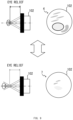
- FIG. 16 is a diagram for explaining an example of configurations of an output unit 260 and an imaging unit 270 ;
- FIG. 17 is a diagram illustrating an example of an image captured by the imaging unit 270 ;
- FIG. 18 is a diagram for explaining a functional configuration of a system according to a fourth embodiment.
- FIG. 19 is a diagram illustrating an output example of auxiliary information in an observation auxiliary device 200 c;
- FIG. 20 is a diagram for explaining a functional configuration of a system according to a fifth embodiment
- FIG. 21 is a diagram illustrating an output example of auxiliary information in an observation auxiliary device 200 d;
- FIG. 22 is a diagram illustrating another example of the superimposed image.
- FIG. 23 is a diagram illustrating still another example of the superimposed image.
- a projection device needs to be incorporated in an existing observation device. It is therefore necessary to significantly change a configuration of the existing observation device.
- FIG. 1 is a diagram for explaining a configuration of a system 1000 according to the present embodiment.
- FIG. 2 is a diagram for explaining a configuration of a superimposed image to be provided to a user.
- the configuration of the system 1000 will be described with reference to FIG. 1 and FIG. 2 .
- the system 1000 includes an observation device 100 and an observation auxiliary device 200 capable of communicating with the observation device 100 .
- an observation device 100 and an observation auxiliary device 200 capable of communicating with the observation device 100 .
- communication between the observation device 100 and the observation auxiliary device 200 is achieved by wireless communication will be described as an example, but the communication between the observation device 100 and the observation auxiliary device 200 may be achieved by wired communication.
- the observation device 100 is, for example, a microscope device.
- the observation device 100 includes an objective 101 and an eyepiece lens 102 .
- the observation device 100 forms an optical image (real image) of a sample on an optical path between the objective 101 and the eyepiece lens 102 .
- the user of the observation device 100 observes, through the eyepiece lens 102 , an optical image 1 (virtual image) obtained by magnifying the optical image (real image) formed by the observation device 100 .
- the control device 105 may generate auxiliary information 3 on the basis of a result of image analysis performed on the digital image 2 .
- the auxiliary information 3 may be information for displaying an outline of a specific target (for example, cells, cell nuclei, etc.) included in the sample as illustrated in FIG. 2 and may be generated on the basis of, for example, an object detection result performed on the digital image 2 .
- the observation device 100 may further include a transmitter 104 for position detection.
- the transmitter 104 may be used to detect a relative position of the observation auxiliary device 200 with respect to the observation device 100 by being used in combination with a receiver 201 which will be described later.
- the relative position of the observation auxiliary device 200 with respect to the observation device 100 will be simply referred to as a relative position.
- the transmitter 104 is preferably provided at the eyepiece lens 102 or near the eyepiece lens 102 as illustrated in FIG. 1 .
- the transmitter 104 preferably transmits a signal that is not perceived by the user, and for example, preferably transmits at least one of an electromagnetic wave outside a visible range or an ultrasonic wave.
- the transmitter 104 may be a magnetic field generator that generates a magnetic field.
- the observation auxiliary device 200 is, for example, smart glasses.
- the observation auxiliary device 200 is a wearable device worn by the user of the observation device 100 and outputs auxiliary information to the user when the user uses the observation device 100 .
- the observation auxiliary device 200 only requires to output the auxiliary information in a mode that allows the user to visually recognize the auxiliary information. More specifically, the observation auxiliary device 200 only requires to output the auxiliary information in such a manner that the user can visually recognize the auxiliary information while observing the optical image of the sample through the eyepiece lens 102 .
- the observation auxiliary device 200 is not limited to the smart glasses and may include, for example, a see-through type head mounted display, may include a contact lens type device (smart contact lens) directly attached to the eyeball, or may include at least one of these.
- a method of outputting the auxiliary information to the user is not particularly limited.
- the observation auxiliary device 200 may include, for example, a device using at least one of a retinal projection method, a retinal scanning method, a hologram method, or a micro LED method and may output the auxiliary information to the user using each method.
- the observation auxiliary device 200 superimposes the auxiliary information 3 on an optical image 1 (virtual image) to be observed by the user through the eyepiece lens 102 on the basis of the relative position.
- the user observes a superimposed image 4 in which the auxiliary information 3 is superimposed on the optical image 1 .
- the auxiliary information 3 By arranging the auxiliary information 3 at an appropriate position of the optical image 1 using the relative position, the user can obtain appropriate information from the auxiliary information 3 included in the superimposed image 4 .
- the observation auxiliary device 200 may include the receiver 201 for position detection.
- the receiver 201 may be used to detect the relative position by being used in combination with the transmitter 104 described above.
- the method of position detection by the transmitter 104 and the receiver 201 is not particularly limited.
- three or more transmitters 104 may be provided in the observation device 100 , and three-point positioning in which positioning is performed by signals from the transmitters 104 may be used as a positioning method.
- three or more receivers 201 may be provided in the observation auxiliary device 200 , and three-point positioning in which positioning is performed by signals received by the receivers 201 may be used as a positioning method.
- the observation device 100 and the observation auxiliary device 200 may detect the relative position by three-point positioning.
- FIG. 3 is a flowchart illustrating an example of processing to be performed by the system 1000 .
- FIG. 4 is a flowchart illustrating an example of auxiliary information acquisition processing to be performed by the system 1000 .
- FIG. 5 is a flowchart illustrating an example of relative position detection processing to be performed by the system 1000 .
- FIG. 6 is a flowchart illustrating an example of auxiliary information output processing to be performed by the system 1000 .
- FIG. 7 is a diagram illustrating an adjustment example of an output position of the auxiliary information 3 by the auxiliary information output processing illustrated in FIG. 6 .
- An observation support method to be performed by the system 1000 will be described with reference to FIGS. 3 to 7 .
- the observation device 100 forms an optical image of the sample placed on a stage (step S 10 ).
- the observation devices 100 collects light from the sample by the objective 101 and a tube lens (not illustrated) to form an optical image of the sample.
- the optical image is formed, for example, on each of the optical paths branching in the trinocular tube and leading to the eyepiece lens 102 and an imaging surface of the digital camera 103 .
- the optical image formed on the optical path to the eyepiece lens 102 is observed by the user through the eyepiece lens 102 .
- the system 1000 acquires auxiliary information (step S 20 ).
- the system 1000 may acquire the auxiliary information by performing the auxiliary information acquisition processing illustrated in FIG. 4 .
- the observation device 100 acquires a digital image (step S 21 ).
- the digital camera 103 converts the optical image formed on the imaging surface into a digital image and outputs the digital image to the control device 105 , so that the observation device 100 acquires the digital image.
- the observation device 100 analyzes the digital image (step S 22 ).
- the control device 105 performs object detection on the digital image to detect a position of a predetermined object in the digital image.
- the observation device 100 generates auxiliary information (step S 23 ).
- the control device 105 generates auxiliary information that draws an outline of the predetermined object on the basis of position information of the predetermined object detected by the object detection, for example.
- the generated auxiliary information is transmitted from the observation device 100 to the observation auxiliary device 200 .
- FIG. 4 illustrates an example where the observation device 100 generates the auxiliary information and the observation auxiliary device 200 acquires the auxiliary information from the observation device 100 as an example of the auxiliary information acquisition processing
- the auxiliary information may be generated by the observation auxiliary device 200 .
- the observation auxiliary device 200 may acquire information (for example, a digital image) different from the auxiliary information from the observation device 100 and generate the auxiliary information on the basis of the acquired information.
- the system 1000 detects the relative position (step S 30 ).
- the system 1000 may detect the relative position by performing the relative position detection processing illustrated in FIG. 5 .
- the observation device 100 transmits a signal (step S 31 ), and the observation auxiliary device 200 receives the signal (step S 32 ).
- the transmitter 104 transmits a signal for position detection (hereinafter, referred to as a position signal), and the receiver 201 receives the position signal.
- the observation auxiliary device 200 calculates the relative position on the basis of the position signal detected by the receiver 201 (step S 33 ).
- the relative position can be calculated using any known method.
- the relative position may be calculated by the observation device 100 .
- a transmitter may be provided in the observation auxiliary device 200
- a receiver may be provided in the observation device 100
- the observation device 100 may calculate the relative position on the basis of the signal received from the observation auxiliary device 200 .
- the calculated information on the relative position is transmitted from the observation device 100 to the observation auxiliary device 200 .
- step S 10 to step S 30 When the processing from step S 10 to step S 30 ends, the system 1000 outputs the auxiliary information and superimposes the auxiliary information on the optical image (step S 40 ).
- the order of the processing from step S 10 to step S 30 is not limited to this example.
- the processing from step S 10 to step S 30 only requires to be performed before the processing of step S 40 .
- the processing from step S 10 to step S 30 may be performed in order different from the order of the processing illustrated in FIG. 3 , or one or more pieces of processing may be performed temporally in parallel.
- step S 40 the system 1000 may superimpose the auxiliary information on the optical image, for example, by performing the auxiliary information output processing illustrated in FIG. 6 .
- the observation auxiliary device 200 calculates a distance and a direction from an optical axis of the eyepiece lens 102 to the observation auxiliary device 200 on the basis of the relative position calculated in step S 33 (step S 41 ) and determines the output position of the auxiliary information on the basis of the calculated distance and direction (step S 42 ).
- the observation auxiliary device 200 outputs the auxiliary information acquired in step S 23 in accordance with the output position determined in step S 42 (step S 43 ).
- the output position of the auxiliary information is appropriately changed on the basis of the distance and the direction calculated in step S 41 , so that the auxiliary information can be output to a position corresponding to the position of the observation auxiliary device 200 with respect to the optical axis of the eyepiece lens 102 .
- the system 1000 can display the auxiliary information 3 at an appropriate position on the optical image 1 by performing the processing illustrated in FIG. 3 described above. This point will be described with reference to FIG. 7 .
- a case where the output position of the auxiliary information 3 from the observation auxiliary device 200 does not change will be considered.
- the observation auxiliary device 200 also moves with respect to the eyepiece lens 102 together with the user, which results in moving the auxiliary information 3 with respect to the optical image 1 .
- the user observes the superimposed image 5 in which the auxiliary information 3 is superimposed at a position shifted from an appropriate position on the optical image 1 .
- the output position of the auxiliary information 3 from the observation auxiliary device 200 changes on the basis of the distance and the direction from the eyepiece lens 102 , so that the shift occurring in the superimposed image 5 described above is eliminated.
- the user can observe the superimposed image 6 in which the auxiliary information 3 is superimposed at an appropriate position on the optical image 1 as illustrated in FIG. 7 .
- the observation device 100 can be configured without making a significant change to the existing observation device. Specifically, the observation device 100 can be configured only by adding the transmitter 104 to an existing observation device, for example. Other necessary changes can be achieved by software processing to be performed by the control device 105 .
- the system 1000 it is possible to provide the user with the auxiliary information together with the optical image without significantly changing the configuration of the existing observation device.
- the auxiliary information can be superimposed and displayed at an appropriate position on the optical image, so that the user can correctly recognize the auxiliary information.
- observation auxiliary device 200 can be configured by, for example, only adding the receiver 201 to existing smart glasses. Other necessary changes can be achieved by software processing to be performed by a processor included in the observation auxiliary device 200 .
- existing smart glasses used for other applications can be used as the observation auxiliary device 200 included in the system 1000 with necessary modifications added.
- the user can use one pair of smart glasses in a plurality of systems including the system 1000 , so that it is possible to avoid inconvenience such as having to replace the smart glasses in accordance with the system to be used.
- FIG. 8 is a flowchart illustrating another example of the auxiliary information output processing to be performed by the system 1000 .
- FIG. 9 is a diagram illustrating an adjustment example of the output position of the auxiliary information 3 by the auxiliary information output processing illustrated in FIG. 8 .
- the system 1000 may perform the auxiliary information output processing illustrated in FIG. 8 instead of the auxiliary information output processing illustrated in FIG. 6 .
- the observation auxiliary device 200 calculates a distance (hereinafter, referred to as a first distance) from the observation device 100 to the observation auxiliary device 200 on the basis of the relative position calculated in step S 33 (step S 51 ) and determines whether or not the calculated first distance is equal to or longer than a predetermined distance (step S 52 ).
- the predetermined distance only requires to be a distance indicating that the user (observation auxiliary device 200 ) is away from the observation device 100 to such an extent that it can be determined that the user is not looking into the eyepiece lens 102 . More specifically, the predetermined distance is determined in advance on the basis of, for example, an eye relief that is a distance from the eyepiece lens 102 to the eye point. In other words, in step S 52 , the observation auxiliary device 200 determines whether or not the distance from the eyepiece lens 102 to the user's eye (for example, the pupil) is sufficiently longer than the eye relief.
- the observation auxiliary device 200 outputs the auxiliary information in accordance with the output position determined in step S 56 (step S 59 ) without performing step S 58 and then ends the auxiliary information output processing.
- the observation auxiliary device 200 stops output of the auxiliary information 3 on the basis of the distance from the observation device 100 to the observation auxiliary device 200 and starts outputting the auxiliary information 3 on the basis of the distance from the observation device 100 to the observation auxiliary device 200 .
- the output unit 220 includes a display element 287 , a lens 288 , and a diffractive light guide element 289 .
- the display element 287 is, for example, a liquid crystal display (LCD).
- Light from the display element 287 is incident on the diffractive light guide element 289 through the lens 288 .
- the diffractive light guide element 289 includes, for example, a transparent flat plate and a diffractive optical element. The light incident on the diffractive light guide element 289 travels while being repeatedly diffracted and reflected to reach a diffractive optical element located in front of the eye 300 , and thereby an image (auxiliary information 8 ) is reproduced.
- the device illustrated in FIG. 13 is an example of a device using a hologram method.
- the observation auxiliary device 200 may include the device using the hologram method.
- the imaging unit 270 includes an imaging element 282 , a half mirror 283 , the lens 284 , and the concave mirror 285 .
- the light from the retina passes through the pupil and is incident on the half mirror 283 via the concave mirror 285 and the lens 284 .
- the imaging element 282 is irradiated with the light reflected by the half mirror 283 , whereby the image of the retina is projected on the imaging element 282 .
Landscapes
- Physics & Mathematics (AREA)
- Engineering & Computer Science (AREA)
- General Physics & Mathematics (AREA)
- Theoretical Computer Science (AREA)
- Remote Sensing (AREA)
- Radar, Positioning & Navigation (AREA)
- Multimedia (AREA)
- Optics & Photonics (AREA)
- General Health & Medical Sciences (AREA)
- Health & Medical Sciences (AREA)
- Electromagnetism (AREA)
- Ophthalmology & Optometry (AREA)
- Human Computer Interaction (AREA)
- Molecular Biology (AREA)
- Biomedical Technology (AREA)
- Life Sciences & Earth Sciences (AREA)
- Microscoopes, Condenser (AREA)
Abstract
Description
Claims (21)
Applications Claiming Priority (2)
| Application Number | Priority Date | Filing Date | Title |
|---|---|---|---|
| JP2021073573A JP7640354B2 (en) | 2021-04-23 | 2021-04-23 | Observation system and observation support method |
| JP2021-073573 | 2021-04-23 |
Publications (2)
| Publication Number | Publication Date |
|---|---|
| US20220343560A1 US20220343560A1 (en) | 2022-10-27 |
| US12033242B2 true US12033242B2 (en) | 2024-07-09 |
Family
ID=83694407
Family Applications (1)
| Application Number | Title | Priority Date | Filing Date |
|---|---|---|---|
| US17/724,688 Active 2042-09-24 US12033242B2 (en) | 2021-04-23 | 2022-04-20 | Observation system and observation support method |
Country Status (2)
| Country | Link |
|---|---|
| US (1) | US12033242B2 (en) |
| JP (1) | JP7640354B2 (en) |
Families Citing this family (2)
| Publication number | Priority date | Publication date | Assignee | Title |
|---|---|---|---|---|
| CN120077770A (en) | 2022-10-19 | 2025-05-30 | 佳能株式会社 | Photoelectric conversion element |
| WO2024096762A1 (en) * | 2022-10-31 | 2024-05-10 | Telefonaktiebolaget Lm Ericsson (Publ) | Eye-worn device for displaying information to an observer |
Citations (4)
| Publication number | Priority date | Publication date | Assignee | Title |
|---|---|---|---|---|
| WO2018231204A1 (en) | 2017-06-13 | 2018-12-20 | Google Llc | Augmented reality microscope for pathology |
| US20200310540A1 (en) * | 2019-03-29 | 2020-10-01 | Facebook Technologies, Llc | Methods and apparatuses for low latency body state prediction based on neuromuscular data |
| US20220350146A1 (en) * | 2019-09-13 | 2022-11-03 | Arizona Board Of Regents On Behalf Of The University Of Arizona | Pupil matched occlusion-capable optical see-through head-mounted display |
| US20230105799A1 (en) * | 2020-06-08 | 2023-04-06 | Hoya Corporation | Program, information processing method, and information processing device |
Family Cites Families (11)
| Publication number | Priority date | Publication date | Assignee | Title |
|---|---|---|---|---|
| JPH05341210A (en) * | 1992-06-09 | 1993-12-24 | Olympus Optical Co Ltd | Stereoscopic endoscope device |
| JP3429529B2 (en) * | 1993-06-15 | 2003-07-22 | オリンパス光学工業株式会社 | Surgical microscope |
| JP4002621B2 (en) * | 1995-09-06 | 2007-11-07 | オリンパス株式会社 | Surgical observation device |
| JP2001056446A (en) * | 1999-08-18 | 2001-02-27 | Sharp Corp | Head mounted display device |
| JP4121845B2 (en) * | 2002-12-13 | 2008-07-23 | オリンパス株式会社 | Surgical microscope |
| JP2014197776A (en) * | 2013-03-29 | 2014-10-16 | 株式会社ニコン | Display device and program |
| JP2015007722A (en) * | 2013-06-25 | 2015-01-15 | キヤノン株式会社 | Image display device |
| JP2015192697A (en) * | 2014-03-31 | 2015-11-05 | ソニー株式会社 | Control device and control method, and photographing control system |
| JP2016158911A (en) * | 2015-03-03 | 2016-09-05 | 株式会社クレッセント | Surgical operation method using image display device, and device using in surgical operation |
| IL252582A0 (en) * | 2017-05-29 | 2017-08-31 | Eyeway Vision Ltd | A method and system for registering between external scenery and a virtual image |
| JP2019022121A (en) * | 2017-07-19 | 2019-02-07 | ソニー株式会社 | Image processing apparatus and method for controlling image processing apparatus |
-
2021
- 2021-04-23 JP JP2021073573A patent/JP7640354B2/en active Active
-
2022
- 2022-04-20 US US17/724,688 patent/US12033242B2/en active Active
Patent Citations (4)
| Publication number | Priority date | Publication date | Assignee | Title |
|---|---|---|---|---|
| WO2018231204A1 (en) | 2017-06-13 | 2018-12-20 | Google Llc | Augmented reality microscope for pathology |
| US20200310540A1 (en) * | 2019-03-29 | 2020-10-01 | Facebook Technologies, Llc | Methods and apparatuses for low latency body state prediction based on neuromuscular data |
| US20220350146A1 (en) * | 2019-09-13 | 2022-11-03 | Arizona Board Of Regents On Behalf Of The University Of Arizona | Pupil matched occlusion-capable optical see-through head-mounted display |
| US20230105799A1 (en) * | 2020-06-08 | 2023-04-06 | Hoya Corporation | Program, information processing method, and information processing device |
Also Published As
| Publication number | Publication date |
|---|---|
| US20220343560A1 (en) | 2022-10-27 |
| JP7640354B2 (en) | 2025-03-05 |
| JP2022167637A (en) | 2022-11-04 |
Similar Documents
| Publication | Publication Date | Title |
|---|---|---|
| US10989911B2 (en) | Method for operating a medical-optical display system | |
| US20130194244A1 (en) | Methods and apparatuses of eye adaptation support | |
| US12239379B2 (en) | Ophthalmic apparatus, method for controlling ophthalmic apparatus, and storage medium | |
| US12033242B2 (en) | Observation system and observation support method | |
| EP3385911B1 (en) | Line of sight detection device and line of sight detection method | |
| EP2422691A1 (en) | Ophthalmologic device | |
| US20260069140A1 (en) | Ophthalmic observation apparatus | |
| US20160206198A1 (en) | Surgical microscope and method for highlighting eye lens pieces | |
| EP3649913A1 (en) | Medical observation device | |
| JP2006308674A (en) | Image display device | |
| EP2556792A1 (en) | A microscope for ophtalmologic surgery | |
| JP3143553B2 (en) | Finder device | |
| EP4027198B1 (en) | Electronic apparatus, electronic apparatus control method, program, and storage medium | |
| US20250380869A1 (en) | Retina imaging apparatus | |
| JP5199009B2 (en) | Fundus camera | |
| JP6293299B2 (en) | Observation apparatus, observation method, and computer program | |
| JPH10307314A (en) | Observation optical device | |
| JPWO2014129522A1 (en) | Fundus imaging apparatus and retinal tissue feature amount measuring method | |
| JP5484505B2 (en) | Ophthalmic imaging equipment | |
| JP2017055233A (en) | Display device, display system, and display device control method | |
| JP2017023416A (en) | Ophthalmologic photographing apparatus, control method therefor, and program | |
| EP4339681A1 (en) | Device for an imaging system, ocular, display apparatus, imaging system, method and computer program | |
| JP2003088502A (en) | Ophthalmic imaging equipment | |
| JP2023128820A (en) | Image processing apparatus, control method thereof, image capturing apparatus, and program | |
| JP2000050313A (en) | Head-mounted display device |
Legal Events
| Date | Code | Title | Description |
|---|---|---|---|
| FEPP | Fee payment procedure |
Free format text: ENTITY STATUS SET TO UNDISCOUNTED (ORIGINAL EVENT CODE: BIG.); ENTITY STATUS OF PATENT OWNER: LARGE ENTITY |
|
| AS | Assignment |
Owner name: OLYMPUS CORPORATION, JAPAN Free format text: ASSIGNMENT OF ASSIGNORS INTEREST;ASSIGNOR:YAMAZAKI, KENTARO;REEL/FRAME:059816/0131 Effective date: 20220419 |
|
| STPP | Information on status: patent application and granting procedure in general |
Free format text: DOCKETED NEW CASE - READY FOR EXAMINATION |
|
| AS | Assignment |
Owner name: EVIDENT CORPORATION, JAPAN Free format text: ASSIGNMENT OF ASSIGNORS INTEREST;ASSIGNOR:OLYMPUS CORPORATION;REEL/FRAME:061008/0214 Effective date: 20220907 |
|
| STPP | Information on status: patent application and granting procedure in general |
Free format text: NON FINAL ACTION MAILED |
|
| STPP | Information on status: patent application and granting procedure in general |
Free format text: RESPONSE TO NON-FINAL OFFICE ACTION ENTERED AND FORWARDED TO EXAMINER |
|
| STPP | Information on status: patent application and granting procedure in general |
Free format text: NOTICE OF ALLOWANCE MAILED -- APPLICATION RECEIVED IN OFFICE OF PUBLICATIONS |
|
| STPP | Information on status: patent application and granting procedure in general |
Free format text: PUBLICATIONS -- ISSUE FEE PAYMENT VERIFIED |
|
| STCF | Information on status: patent grant |
Free format text: PATENTED CASE |