JP2010148586A - Fundus camera - Google Patents
Fundus camera Download PDFInfo
- Publication number
- JP2010148586A JP2010148586A JP2008327916A JP2008327916A JP2010148586A JP 2010148586 A JP2010148586 A JP 2010148586A JP 2008327916 A JP2008327916 A JP 2008327916A JP 2008327916 A JP2008327916 A JP 2008327916A JP 2010148586 A JP2010148586 A JP 2010148586A
- Authority
- JP
- Japan
- Prior art keywords
- image
- fundus
- eye
- index
- focus
- Prior art date
- Legal status (The legal status is an assumption and is not a legal conclusion. Google has not performed a legal analysis and makes no representation as to the accuracy of the status listed.)
- Pending
Links
Images


Classifications
-
- A—HUMAN NECESSITIES
- A61—MEDICAL OR VETERINARY SCIENCE; HYGIENE
- A61B—DIAGNOSIS; SURGERY; IDENTIFICATION
- A61B3/00—Apparatus for testing the eyes; Instruments for examining the eyes
- A61B3/10—Objective types, i.e. instruments for examining the eyes independent of the patients' perceptions or reactions
- A61B3/12—Objective types, i.e. instruments for examining the eyes independent of the patients' perceptions or reactions for looking at the eye fundus, e.g. ophthalmoscopes
Abstract
Description
本発明は、フォーカス指標をモニタ観察しながら撮影を行う眼底カメラに関するものである。 The present invention relates to a fundus camera that performs imaging while observing a focus index on a monitor.
従来、眼底カメラのフォーカス操作は、被検眼の眼底にスプリット光束を投影し、ファインダ観察等の画面を観察しながら、フォーカスレンズを移動させることにより、フォーカス指標のスプリット指標像が一直線になるように操作することにより行っている。 Conventionally, the focus operation of the fundus camera is performed by projecting a split light beam onto the fundus of the eye to be examined and moving the focus lens while observing a screen such as a viewfinder observation so that the split index image of the focus index is in a straight line. It is done by operating.
特許文献1においては、内蔵モニタに撮影された眼底画像を拡大表示する技術が開示されている。更に、特許文献2においては、汎用デジタルカメラで撮影された画像を再生表示したり、撮影モードを切換える制御手段が開示されている。
近年、汎用デジタルカメラの普及により、眼底カメラの撮影部に利用することが多くなってきており、上述の汎用デジタルカメラの背面には撮影前の眼底観察や撮影後の再生をするための液晶モニタが配置されている。 In recent years, with the widespread use of general-purpose digital cameras, it has been increasingly used in the photographing unit of fundus cameras. On the back of the above-mentioned general-purpose digital cameras, a liquid crystal monitor for observing the fundus before photographing and reproducing after photographing Is arranged.
また、眼底カメラの小型化、コストダウンのために、汎用デジタルカメラ又は液晶付きカメラモジュールユニットが装着されるものが増加している。 In addition, in order to reduce the size and cost of fundus cameras, the number of cameras equipped with general-purpose digital cameras or camera module units with liquid crystals is increasing.
しかし、従来のフォーカス指標は小さく、フォーカス合わせが難しいという問題を有している。 However, the conventional focus index is small and has a problem that focusing is difficult.
本発明の目的は、上述の課題を解消し、フォーカス合わせにおいて観察時に中心部を拡大して表示することが可能な眼底カメラを提供することにある。 An object of the present invention is to provide a fundus camera capable of solving the above-described problems and enlarging and displaying a central portion during observation in focusing.
上記目的を達成するための本発明に係る眼底カメラは、被検眼の眼底を照明する照明手段を有する照明光学系と、撮像素子を有し眼底像を観察する眼底観察撮影光学系と、被検眼の眼底の撮影部位の中心領域にフォーカス指標を投影するフォーカス指標投影手段と、前記撮像素子により撮像された眼底像を表示する表示手段と、前記撮像素子により撮像され前記フォーカス指標が投影された中心領域を電気的に拡大する拡大手段と、該拡大手段の出力と前記撮像素子により撮像された周辺部位の画像出力とを合成する画像合成手段と、前記表示手段に前記画像合成手段の出力を出力する出力手段とを備えたことを特徴とする。 In order to achieve the above object, a fundus camera according to the present invention includes an illumination optical system having illumination means for illuminating the fundus of a subject's eye, a fundus observation photographing optical system that has an image sensor and observes a fundus image, and an eye to be examined A focus index projection means for projecting a focus index on the center region of the imaging region of the fundus oculi, a display means for displaying a fundus image captured by the image sensor, and a center on which the focus index is projected by the image sensor Enlarging means for electrically enlarging the region, image synthesizing means for synthesizing the output of the enlarging means and the image output of the peripheral part imaged by the imaging device, and outputting the output of the image synthesizing means to the display means Output means.
本発明に係る眼底カメラによれば、眼底像のピント合わせ時に中心領域を拡大表示することにより、弱視者であっても眼底カメラのフォーカス状態を見易くすることができる。また、周辺部位のフレア観察と中心にあるフォーカス指標を同時に見易い状態で確認することができる。 According to the fundus camera of the present invention, it is possible to make it easy to see the focus state of the fundus camera, even for a weak eyesight person, by enlarging and displaying the center area when focusing the fundus image. In addition, it is possible to confirm the flare observation of the peripheral part and the focus index at the center simultaneously in an easy-to-see state.
本発明を図示の実施例に基づいて詳細に説明する。 The present invention will be described in detail based on the embodiments shown in the drawings.
図1は本実施例1における眼底カメラの光学系の構成図を示している。被検眼Eの前方の光路L1上には、対物レンズ1、前眼観察レンズ2、孔あきミラー3、フォーカスレンズ4、結像レンズ5、ダイクロイックリターンミラー6、撮像素子7が順次に配列され、眼底観察撮影光学系が構成されている。なお、前眼観察レンズ2は光路L1に挿脱自在とされ、フォーカスレンズ4は光路L1方向に移動可能とされている。
FIG. 1 shows a configuration diagram of an optical system of a fundus camera in the first embodiment. On the optical path L1 in front of the eye E, an
孔あきミラー3の入射方向の光路L2上には、角膜バッフル8、リレーレンズ9、ピント合わせのために光路方向に移動可能なフォーカス指標投影ユニット10、リレーレンズ11、折り返しミラー12が順次に配置されている。フォーカス指標投影ユニット10は光路L2に挿脱自在であると共に、光路L2方向に移動可能とされ、この移動はフォーカスレンズ4と連動されている。また、フォーカス指標投影ユニット10の中心部には、光束を分割する小さなプリズム13が配置され、端部にはフォーカス指標LED14が配置されている。
On the optical path L2 in the incident direction of the
折り返しミラー12の反射方向には、水晶体バッフル15、レンズ16、ストロボ管から成る撮影光源17、可視光をカットする可視光カットフィルタ18、ハロゲンランプから成る観察光源19が順次に配列されている。更に、観察光源19の後方には、半球状の反射ミラー20が配置され、照明光学系が構成されている。
In the reflection direction of the
また、ダイクロイックリターンミラー6の反射方向には、被検眼Eの視線方向を誘導するためのマトリック状にLEDが配置された内部固視標21が設けられている。更に、孔あきミラー3の近傍に位置する2本の光ファイバ22を介して、孔あきミラー3の付近から対物レンズ1を介して、被検眼Eの角膜にアライメント指標を表示するアライメント指標LED23が設けられている。
Further, in the reflection direction of the
図2は眼底カメラの側面図を示しており、眼底カメラの可動台31には、ジョイスティック32が設けられ、その上に撮影開始スイッチ33が設けられている。また可動台31には、前眼観察レンズ切換スイッチ34、左右何れの眼を撮影する状態なのかを検知する左右眼検知スイッチ35が設けられている。また、可動台31上の撮影部本体36には、表示モードを切換える拡大画像表示切換スイッチ37、フォーカスレンズ4を駆動するフォーカス駆動操作部38が設けられている。
FIG. 2 shows a side view of the fundus camera. A
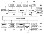
図3は本実施例における眼底カメラのブロック回路構成図を示している。眼底カメラには中央演算処理回路41が設けられ、撮影開始スイッチ33、前眼観察レンズ切換スイッチ34、拡大画像表示切換スイッチ37が入力手段として接続されている。更に、中央演算処理回路41には、駆動制御回路42を介してダイクロイックリターンミラー6を駆動する駆動手段43、フォーカス指標投影ユニット10を光路L2に挿脱する駆動手段44、前眼観察レンズ2を光路L1に挿脱する駆動手段45が接続されている。
FIG. 3 shows a block circuit configuration diagram of the fundus camera in the present embodiment. The fundus camera is provided with a
中央演算処理回路41の出力は、D/A回路46を介してフォーカス指標LED14、内部固視標21、アライメント指標LED23に接続され、撮影操作時にオン/オフの制御ができるようになっている。更に中央演算処理回路41の出力は、充電回路を含む発光回路47を介して、撮影光源17、観察光源19が接続されている。また、中央演算処理回路41の出力は画像処理回路48を介して表示装置49に接続され、撮像素子7により撮像した画像信号が画像処理回路48に接続されている。
The output of the
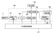
図4は画像処理回路48のブロック回路構成図を示しており、画像処理回路48には撮像素子7から入力された動画像をフレームレートごとに制御し、デジタル変換する画像A/D回路51が設けられている。この画像A/D回路51の出力は撮像素子7により取り込まれた画像出力を記憶するメモリ52を介して、画像の一部を抽出し電気的に拡大する画像拡大回路53、画像を合成する画像合成回路54に接続されている。また、メモリ52の出力は画像合成回路54に接続されている。
FIG. 4 shows a block circuit configuration diagram of the
更に、画像処理回路48には電子画像マスクを発生する画像発生マスク回路55及びキャラクタを発生するキャラクタ発生回路56が内蔵され、これらの回路55、56の出力は画像合成回路54に接続されている。そして、画像合成回路54の出力は表示装置49に接続されている。また、中央演算処理回路41の出力は、画像A/D回路51、メモリ52、画像拡大回路53、画像合成回路54、画像発生マスク回路55、キャラクタ発生回路56に接続されている。
Further, the
被検眼Eの眼底観察、撮影に際しては、先ず被検眼Eの前眼部に対するアライメントを行う。検者は前眼観察レンズ切換スイッチ34を操作し、駆動手段45により前眼観察レンズ2を光路L1に挿入し、前眼部観察を可能とする。この状態で、ジョイスティック32を操作して撮影部本体36を動かし、前眼部の瞳孔が画像の中心に位置するようにアライメントを行う。
In observing and photographing the fundus of the eye E, first, alignment of the eye E with the anterior eye portion is performed. The examiner operates the anterior eye observation
このアライメントがなされた後に前眼観察レンズ切換スイッチ34を操作し、前眼観察レンズ2を光路L1から退避させ、眼底を観察できる状態とする。発光回路47を介して観察光源19から発せられた観察光は、可視光カットフィルタ18において、可視光をカットされ被検眼Eに眩しさを感じさせない赤外光とされた後に、レンズ16、水晶体バッフル15を経て折り返しミラー12に入射する。折り返しミラー12で反射された光束は、リレーレンズ11、9、角膜バッフル8を経て、孔あきミラー3の周辺部に入射する。更に、孔あきミラー3において反射された光束は、対物レンズ1を介して被検眼Eの眼底を照明する。
After this alignment, the anterior eye observation
被検眼Eの眼底で反射された眼底像は、対物レンズ1、孔あきミラー3の孔部付近の絞りを通り、フォーカスレンズ4、結像レンズ5、ダイクロイックリターンミラー6を透過し撮像素子7に結像する。撮像素子7において結像された像は倒立像であるが、画像処理回路48で上下反転させ正立像として表示装置49で観察できる。
The fundus image reflected by the fundus of the eye E passes through the
内部固視標21から発した光束はダイクロイックリターンミラー6で反射され、結像レンズ5、フォーカスレンズ4、孔あきミラー3、対物レンズ1を経て被検眼Eの眼底に投影され、被検眼Eの視線誘導を行う。
The light beam emitted from the
通常では、眼底カメラは撮像素子7で受光される円形の光学像に合わせて、余分な有害光を表示しないように、光学系の眼底結像位置に開口部を配置する。本実施例においては、図5に示すように画像発生マスク回路55により電子画像で開口部マスク61を生成し、画像合成回路54によって眼底像Fと合成し表示装置49に表示する。
Normally, the fundus camera arranges an opening at the fundus imaging position of the optical system so as not to display extraneous harmful light in accordance with the circular optical image received by the
図6はマスク画像を合成した画像を示している。図6(a)アライメント指標LED23による指標光の角膜反射像を適正作動距離に合わせるためのアライメント用の指標枠62、63、右眼/左眼情報64を表示した状態の画面を示している。眼底カメラの可動台31の左右眼検知スイッチ35により、左右何れの眼を観察している状態であるかを検知し、キャラクタ発生回路56において、右眼又は左眼の情報64をキャラクタ発生回路56で発生させる。
FIG. 6 shows an image obtained by combining the mask images. FIG. 6A shows a screen in which index frames 62 and 63 for alignment and right eye /
また、アライメント指標LED23を発した光束は、光ファイバ22の端面に入射し、光ファイバ22内を導光されて、孔あきミラー3の孔部付近に配置された出射端面を照明する。この光ファイバ22の出射端面は、被検眼Eと孔あきミラー3の距離が適正であるときは、被検眼Eの角膜頂点から角膜の曲率半径の半分の距離の位置に投影されるように配置されており、その出射端面が投影指標を形成している。従って、投影指標である出射端面の像は、上述の位置に投影された後に、被検眼Eの角膜により反射され、再び孔あきミラー3の孔部、フォーカスレンズ4、結像レンズ5を通って撮像素子7に結像して電気信号に変換される。
Further, the light beam emitted from the
更に、この信号は画像処理回路48に入力され、光ファイバ22の出射端面である角膜反射像である指標像A1、A2が表示装置49に映し出されアライメント状態が表示される。撮影者はこの指標像A1、A2のコントラストが明瞭になり、2つの指標像A1、A2が指標枠62、63内に位置するように、ジョイスティック32により被検眼Eと撮影部本体36との作動距離を調整する。そして、被検眼Eの作動距離が合うと、図6(b)に示すように指標枠62、63内に指標像A1、A2が位置することになる。
Further, this signal is input to the
また、フォーカス指標投影ユニット10のフォーカス指標LED14から発した光束は、プリズム13で反射され、上述の観察光と同様の経路を経て撮像素子7に導かれ、表示装置49における眼底の撮影部位の中心領域にフォーカス指標fが表示される。フォーカス駆動操作部38により、フォーカスレンズ4と共に、フォーカス指標投影ユニット10を光路L2方向に移動させることによって、被検眼Eの眼底上にフォーカス指標fを表示しその状態を変化させることができる。しかし、この図6におけるフォーカス指標fは小さく、正確にピント合わせを行うために、後述するようにこのフォーカス指標fを拡大して表示する。
The light beam emitted from the focus index LED 14 of the focus
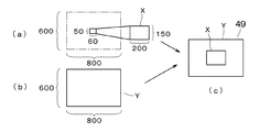
フレームレートごとに撮像素子7で得られた画像は、画像A/D回路51でA/D変換される。仮に、800×600画素表示させるとすると、1ライン水平方向に800分割でA/D変換され、垂直方向に600ラインのA/D変換することが基本制御となっている。
An image obtained by the
図7は画像の拡大方法の概略図を示している。拡大画像表示切換スイッチ37からの画像拡大指令が入力されると、中央演算処理回路41は図7(a)に示すように操作部位の中心領域の範囲(60×50画素)の画像Xだけ、水平方向のA/D変換周波数を1/3.3に細分化する。そして、取り込み画素を細分化した画像をメモリ52に記憶し、記憶された画像は画像拡大回路53及び画像合成回路54に取り込まれる。
FIG. 7 shows a schematic diagram of an image enlargement method. When an image enlargement command is input from the enlarged image
画像拡大回路53においては、中心領域の範囲のみが送られ、水平方向のA/D取り込み周波数を1/3.3にすることにより、200画素分が取り込まれる。垂直方向は50ライン分を各ライン3倍分に画素を増加し、150ライン分を生成する。従って、抽出された60×50画素は200×150画素に拡大される。
In the
図7(a)に示す拡大されたこの中心領域の画像Xを、(b)に示す周辺部位の画像Yに対し中心領域の200×150画素分を入れ代えることにより、(c)に示すように合成する。この画像制御をフレームごとに行うことで、中心領域が拡大された表示モードで動画像を表示装置49に表示することができる。画像拡大指令が中止されると、取り込み画像は元の800×600画素のA/D変換レートに戻る。
As shown in (c), the enlarged image X of the central region shown in FIG. 7 (a) is replaced with the center region of 200 × 150 pixels with respect to the peripheral portion image Y shown in (b). To synthesize. By performing this image control for each frame, a moving image can be displayed on the
なお、この画像拡大処理は次の方法でも実施可能である。例えば、画像A/D回路51で画像の取り込みレートを水平方向1/4、即ち4倍の画素を取り込む。つまり、垂直方向に2400ラインを取り込める撮像手段を使用することで、常時、図8(a)に示すように3200×2400の画像をメモリ52に取り込む。画像拡大回路53では、この中心領域の200×150画素を抽出する処理を行う。
This image enlargement process can also be performed by the following method. For example, the image A /
メモリ52から画像合成回路54には、図8(b)に示すように、3200×2400の画像の内、4画素跳びで画像を間引きし800×600画素が取り込まれる。ここで、中心領域の200×150画素を入れ代える処理を行うことにより、中心領域の画像Xを拡大することができる。
As shown in FIG. 8B, the image is thinned out by skipping four pixels out of the 3200 × 2400 image, and 800 × 600 pixels are taken into the
更に、変形例として、上述した3200×2400の画像をフレームごとに中心領域と周辺部位を分けて取り込む。そして、偶数フレームにおいては、中心領域の200×150画素を取り込み、奇数フレームでは3200×2400の画像の4画素跳び間引いて800×600画素を取り込む。偶数フレームは画像拡大回路53に、奇数フレームは画像合成回路54に送信し、中心領域を入れ代える処理が行われ、中心領域の200×150画素のみ拡大した画像Xが得られる。
Furthermore, as a modification, the above-described 3200 × 2400 image is captured by dividing the central region and the peripheral portion for each frame. Then, in the even frame, 200 × 150 pixels in the central region are captured, and in the odd frame, 800 × 600 pixels are captured by skipping 4 pixels of the 3200 × 2400 image. The even frame is transmitted to the
拡大画像表示切換スイッチ37を押すと、図9に示すように表示装置49には、赤外観察像の中心領域のフォーカス指標fが拡大されて表示される。上述した3200×2400の画像の取り込みでは、全ての画素をメモリ52に記憶することで、表示解像力の高い表示装置で表示する場合でも対応できる。
When the enlarged image
図10は拡大表示されたフォーカス指標fを用いたピント合わせの説明図である。(a)、(c)のように左右のスプリット像がずれているときはピントが合っていない状態である。そして、フォーカス駆動操作部38を操作しフォーカスレンズ4を動作させ、(b)に示すようにフォーカス指標が直線状になったときがピントが合った状態である。
FIG. 10 is an explanatory diagram of focusing using the enlarged focus index f. When the left and right split images are deviated as in (a) and (c), the image is out of focus. Then, when the
なお、本実施例においては拡大画像表示切換スイッチ37により、フォーカス指標fを拡大画面により観察し、眼底へのピント合わせ調整を容易にしている。しかし、拡大画像表示切換スイッチ37の操作の代りに、前眼観察から眼底観察に切換える前眼観察レンズ切換スイッチ34の入力により画像拡大の指令を出力してもよい。
In this embodiment, the enlarged image
フォーカス指標fによるピントが合った状態で撮影開始スイッチ33を押すと、撮影状態に切換わる。駆動手段44によりフォーカス指標投影ユニット10を光路L2から退避し、駆動手段43によりダイクロイックリターンミラー6を跳ね上げた後に、発光回路47により撮影光源17から撮影光を発する。この撮影光はレンズ16、水晶体バッフル15の開口部を通り、折り返しミラー12において反射され、観察光と同様の光路を経て被検眼Eの眼底を照射する。
When the shooting start
そして、眼底から反射された光束は、対物レンズ1、孔あきミラー3の孔部を通り、フォーカスレンズ4、結像レンズ5を経て撮像素子7に入射し、撮像素子7の最大画素を使用することで、高画質のカラー眼底画像が得られる。
Then, the light beam reflected from the fundus passes through the hole of the
1 対物レンズ
2 前眼観察レンズ
3 孔あきミラー
7 撮像素子
10 フォーカス指標投影ユニット
17 撮影光源
19 観察光源
21 内部固視標
23 アライメント指標LED
32 ジョイスティック
33 撮影開始スイッチ
34 前眼観察レンズ切換スイッチ
35 左右眼検知スイッチ
36 撮影部本体
37 拡大画像表示切換スイッチ
41 中央演算処理回路
48 画像処理回路
49 表示装置
52 メモリ
53 画像拡大回路
54 画像合成回路
55 画像発生マスク回路
56 キャラクタ発生回路
61 開口部マスク
62、63 指標枠
DESCRIPTION OF
32
Claims (4)
Priority Applications (2)
| Application Number | Priority Date | Filing Date | Title |
|---|---|---|---|
| JP2008327916A JP2010148586A (en) | 2008-12-24 | 2008-12-24 | Fundus camera |
| US12/641,760 US7896494B2 (en) | 2008-12-24 | 2009-12-18 | Fundus camera |
Applications Claiming Priority (1)
| Application Number | Priority Date | Filing Date | Title |
|---|---|---|---|
| JP2008327916A JP2010148586A (en) | 2008-12-24 | 2008-12-24 | Fundus camera |
Publications (2)
| Publication Number | Publication Date |
|---|---|
| JP2010148586A true JP2010148586A (en) | 2010-07-08 |
| JP2010148586A5 JP2010148586A5 (en) | 2012-02-16 |
Family
ID=42265552
Family Applications (1)
| Application Number | Title | Priority Date | Filing Date |
|---|---|---|---|
| JP2008327916A Pending JP2010148586A (en) | 2008-12-24 | 2008-12-24 | Fundus camera |
Country Status (2)
| Country | Link |
|---|---|
| US (1) | US7896494B2 (en) |
| JP (1) | JP2010148586A (en) |
Cited By (5)
| Publication number | Priority date | Publication date | Assignee | Title |
|---|---|---|---|---|
| JP2014094162A (en) * | 2012-11-09 | 2014-05-22 | Canon Inc | Ophthalmologic imaging device |
| JP2014200511A (en) * | 2013-04-05 | 2014-10-27 | 地方独立行政法人山口県産業技術センター | Fundus image-capturing system, and fundus image-capturing method |
| JP2015066242A (en) * | 2013-09-30 | 2015-04-13 | 株式会社ニデック | Ophthalmology imaging apparatus |
| US9603520B2 (en) | 2012-11-09 | 2017-03-28 | Canon Kabushiki Kaisha | Ophthalmic apparatus, image processing method, and storage medium |
| JP2018089480A (en) * | 2018-03-15 | 2018-06-14 | キヤノン株式会社 | Ophthalmic photographing system, method for controlling the same and program |
Families Citing this family (1)
| Publication number | Priority date | Publication date | Assignee | Title |
|---|---|---|---|---|
| CA2856075A1 (en) * | 2011-11-18 | 2013-05-23 | Optovue, Inc. | Fundus camera |
Citations (3)
| Publication number | Priority date | Publication date | Assignee | Title |
|---|---|---|---|---|
| JPH0595902A (en) * | 1991-10-08 | 1993-04-20 | Canon Inc | Eyeground camera |
| JPH05192299A (en) * | 1992-01-21 | 1993-08-03 | Topcon Corp | Fundus camera |
| JP2002325733A (en) * | 2001-05-01 | 2002-11-12 | Canon Inc | Ophthalmologic instrument |
Family Cites Families (4)
| Publication number | Priority date | Publication date | Assignee | Title |
|---|---|---|---|---|
| JP4138533B2 (en) * | 2003-02-28 | 2008-08-27 | 株式会社ニデック | Fundus camera |
| JP4515851B2 (en) | 2004-07-30 | 2010-08-04 | 株式会社ニデック | Ophthalmic imaging equipment |
| JP4693402B2 (en) * | 2004-12-15 | 2011-06-01 | 興和株式会社 | Ophthalmic imaging equipment |
| JP4878277B2 (en) * | 2006-11-29 | 2012-02-15 | キヤノン株式会社 | Ophthalmic photographing apparatus and focus unit used for the ophthalmic photographing apparatus |
-
2008
- 2008-12-24 JP JP2008327916A patent/JP2010148586A/en active Pending
-
2009
- 2009-12-18 US US12/641,760 patent/US7896494B2/en not_active Expired - Fee Related
Patent Citations (3)
| Publication number | Priority date | Publication date | Assignee | Title |
|---|---|---|---|---|
| JPH0595902A (en) * | 1991-10-08 | 1993-04-20 | Canon Inc | Eyeground camera |
| JPH05192299A (en) * | 1992-01-21 | 1993-08-03 | Topcon Corp | Fundus camera |
| JP2002325733A (en) * | 2001-05-01 | 2002-11-12 | Canon Inc | Ophthalmologic instrument |
Cited By (5)
| Publication number | Priority date | Publication date | Assignee | Title |
|---|---|---|---|---|
| JP2014094162A (en) * | 2012-11-09 | 2014-05-22 | Canon Inc | Ophthalmologic imaging device |
| US9603520B2 (en) | 2012-11-09 | 2017-03-28 | Canon Kabushiki Kaisha | Ophthalmic apparatus, image processing method, and storage medium |
| JP2014200511A (en) * | 2013-04-05 | 2014-10-27 | 地方独立行政法人山口県産業技術センター | Fundus image-capturing system, and fundus image-capturing method |
| JP2015066242A (en) * | 2013-09-30 | 2015-04-13 | 株式会社ニデック | Ophthalmology imaging apparatus |
| JP2018089480A (en) * | 2018-03-15 | 2018-06-14 | キヤノン株式会社 | Ophthalmic photographing system, method for controlling the same and program |
Also Published As
| Publication number | Publication date |
|---|---|
| US7896494B2 (en) | 2011-03-01 |
| US20100157245A1 (en) | 2010-06-24 |
Similar Documents
| Publication | Publication Date | Title |
|---|---|---|
| US7798642B2 (en) | Fundus camera | |
| US7572009B2 (en) | Method and apparatus for processing an eye fundus image | |
| US9084567B2 (en) | Fundus imaging apparatus and method therefor | |
| JP5021007B2 (en) | Ophthalmic photographing apparatus and camera used in the ophthalmic photographing apparatus | |
| US7848625B2 (en) | Imaging system | |
| US7896494B2 (en) | Fundus camera | |
| JP2015091309A (en) | Ophthalmologic image processor and image processing program | |
| JP5772101B2 (en) | Fundus photographing device | |
| JP2000005131A (en) | Fundus camera | |
| JP3576671B2 (en) | Ophthalmic imaging equipment | |
| JP2009285108A (en) | Ophthalmic photographic apparatus | |
| JP2000232961A (en) | Fundus camera | |
| JP2003210409A (en) | Fundus camera | |
| JP4520244B2 (en) | Fundus camera | |
| JP7355194B2 (en) | fundus imaging device | |
| JPH105179A (en) | Ophthalmologic photographing device | |
| JP4659173B2 (en) | Fundus camera | |
| JP2012075925A (en) | Image processor and method thereof | |
| JP2011030689A (en) | Fundus photographing system and method for processing three-dimensional fundus image | |
| US8764190B2 (en) | Fundus camera | |
| JP5546581B2 (en) | Ophthalmic photographing apparatus, control method for ophthalmic photographing apparatus, camera detachable from fundus camera main body, control apparatus, control method, and ophthalmic system | |
| JP5755200B2 (en) | Ophthalmic imaging apparatus and method | |
| JP2006075449A (en) | Ophthalmic imaging apparatus | |
| JP2017064188A (en) | Ocular fundus photographing apparatus | |
| JP2003126041A (en) | Ophthalmologic photographic device |
Legal Events
| Date | Code | Title | Description |
|---|---|---|---|
| RD01 | Notification of change of attorney |
Free format text: JAPANESE INTERMEDIATE CODE: A7421 Effective date: 20100630 |
|
| A521 | Request for written amendment filed |
Free format text: JAPANESE INTERMEDIATE CODE: A523 Effective date: 20111221 |
|
| A621 | Written request for application examination |
Free format text: JAPANESE INTERMEDIATE CODE: A621 Effective date: 20111221 |
|
| A977 | Report on retrieval |
Free format text: JAPANESE INTERMEDIATE CODE: A971007 Effective date: 20130204 |
|
| A131 | Notification of reasons for refusal |
Free format text: JAPANESE INTERMEDIATE CODE: A131 Effective date: 20130409 |
|
| A521 | Request for written amendment filed |
Free format text: JAPANESE INTERMEDIATE CODE: A523 Effective date: 20130610 |
|
| A131 | Notification of reasons for refusal |
Free format text: JAPANESE INTERMEDIATE CODE: A131 Effective date: 20130924 |
|
| A02 | Decision of refusal |
Free format text: JAPANESE INTERMEDIATE CODE: A02 Effective date: 20140513 |