US12031993B2 - Blood testing system and method - Google Patents
Blood testing system and method Download PDFInfo
- Publication number
- US12031993B2 US12031993B2 US16/708,334 US201916708334A US12031993B2 US 12031993 B2 US12031993 B2 US 12031993B2 US 201916708334 A US201916708334 A US 201916708334A US 12031993 B2 US12031993 B2 US 12031993B2
- Authority
- US
- United States
- Prior art keywords
- chamber
- blood
- reagent
- cartridge
- mixing
- Prior art date
- Legal status (The legal status is an assumption and is not a legal conclusion. Google has not performed a legal analysis and makes no representation as to the accuracy of the status listed.)
- Active, expires
Links
Images


Classifications
-
- G—PHYSICS
- G01—MEASURING; TESTING
- G01N—INVESTIGATING OR ANALYSING MATERIALS BY DETERMINING THEIR CHEMICAL OR PHYSICAL PROPERTIES
- G01N33/00—Investigating or analysing materials by specific methods not covered by groups G01N1/00 - G01N31/00
- G01N33/48—Biological material, e.g. blood, urine; Haemocytometers
- G01N33/50—Chemical analysis of biological material, e.g. blood, urine; Testing involving biospecific ligand binding methods; Immunological testing
- G01N33/86—Chemical analysis of biological material, e.g. blood, urine; Testing involving biospecific ligand binding methods; Immunological testing involving blood coagulating time or factors, or their receptors
-
- G—PHYSICS
- G01—MEASURING; TESTING
- G01N—INVESTIGATING OR ANALYSING MATERIALS BY DETERMINING THEIR CHEMICAL OR PHYSICAL PROPERTIES
- G01N33/00—Investigating or analysing materials by specific methods not covered by groups G01N1/00 - G01N31/00
- G01N33/48—Biological material, e.g. blood, urine; Haemocytometers
- G01N33/483—Physical analysis of biological material
- G01N33/487—Physical analysis of biological material of liquid biological material
- G01N33/49—Blood
- G01N33/4905—Determining clotting time of blood
Definitions
- This document relates to systems and method for testing characteristics of a blood sample, such as an automated thromboelastometry system for point-of-care whole blood coagulation analysis.
- viscoelastic methods Another group of tests to assess the potential of blood to form an adequate clot is known as “viscoelastic methods.”
- the blood clot firmness (or other parameters dependent thereon) is determined over a period of time, for example, from the formation of the first fibrin fibers until the dissolution of the blood clot by fibrinolysis.
- Blood clot firmness is a functional parameter which contributes to hemostasis in vivo, as a clot must resist blood pressure and shear stress at the site of vascular injury or incision.
- clot firmness may result from multiple interlinked processes including coagulation activation, thrombin formation, fibrin formation and polymerization, platelet activation, and fibrin-platelet interaction.
- reagent compounds can be mixed with the blood sample to activate or inhibit certain components in the blood sample.
- liquid reagents are injected into a disposable plastic cup containing a blood sample, and the cup is then engaged by the control console of the blood testing system to evaluate characteristics of the coagulation/clotting of the blood sample.
- the system requires manual intervention by the operator for each of the assays, for example, when pipettes are used by an operator for the dispensing and measuring of the reagents, blood, and mixed samples.
- a system for testing characteristics of a blood sample can include a cartridge configured to mate with a control console and receive a blood sample for a point-of-care whole blood coagulation analysis.
- the cartridge is configured to interact with the control console so as to perform a number of automated transport and testing operations on portions of the blood sample so as to provide reliable and prompt results indicative of a patient's blood characteristics at the point-of-care (e.g., while the patient is in a surgical room undergoing surgery).
- the system can serve as an automated thromboelastometry system for providing detailed and prompt results of blood coagulation characteristics in response to receiving a cartridge (and blood sample at the cartridge) and an indication from an operator to begin the automated testing process.
- the thromboelastometry system includes a reusable analyzer console and one or more single-use cartridge components configured to mate with the console.
- a user inserts the cartridge into the analyzer console and, when prompted by the analyzer console, inserts a blood collection tube (containing a whole blood sample) into a receiver portion of the cartridge.
- the user is then prompted a user interface of the analyzer console to initiate a number of automated blood transfer and testing operations.
- the analyzer console automatically performs (without requiring further user interaction with the cartridge or the blood sample) the testing and displays the results on a graphical display using qualitative graphical representations and quantitative parameters.
- a cartridge device for a measuring system for measuring viscoelastic characteristics of a blood sample may include a plurality of reagent mixing chambers for receiving and mixing a predetermined amount of a blood sample with one or more reagent beads.
- the cartridge device may also include a movable mixing element retained with the reagent mixing chamber.
- the movable mixing element may comprise a material that is inert relative to the blood sample.
- the cartridge device may further include a plurality of retaining elements extending into the reagent mixing chamber so as to maintain the reagent mixing beads in positions that are spaced apart from the movable mixing element.
- the blood testing cartridge (and, optionally, the blood collection reservoir) can be equipped with one or more computer-readable components so as to promptly transfer relevant information of the analyzer console for each blood sample testing cycle.
- each cartridge can be labeled with a barcode, near-field communication tag, and RFID tag, or the like that includes information such as, but not limited to, the types of assays to be performed by the cartridge, the type of reagents container within the cartridge, manufacturer information, an expiration date, or the like.
- the analyzer console can include a barcode reader (or a reader for a near-field communication tag, a RFID tag, or the like) that scans the barcode upon insertion of the cartridge into the analyzer console.
- FIG. 10 A is a top view of the cartridge component of FIG. 4 .
- FIG. 10 C is a schematic diagram depicting the partial cross-sectional view of the cartridge component of FIG. 10 B in conjunction with associated components of an analyzer console of the thromboelastometry system of FIGS. 1 A, 1 B, 2 , and 3 .
- a blood testing system 100 include an analyzer console 140 and one or more cartridges 120 configured to releasably mate with analyzer console 140 .
- the blood testing system 100 is a thromboelastometry system that is configured to determine a number of blood coagulation characteristics of a blood sample input into the cartridge 120 .
- the cartridge 120 can be configured as a single-use cartridge that includes a blood sample receiver 122 for mating with a blood sample reservoir 10 (e.g., a vacutainer sample tube supplied by Becton, Dickinson & Company of Franklin Lakes, N.J., or another blood reservoir structure).
- an adapter may be used to couple other types of blood sample reservoirs 10 with the cartridge 120 (e.g., tubing may be used through which blood can be injected into the cartridge 120 , and the like).
- the thromboelastometry system 10 can be used as a whole blood coagulation analysis system that is particularly advantageous at a point-of-care site (e.g., in a surgical theater while a patient is undergoing or preparing for surgery, or the like).
- thromboelastometry system 100 can be used as a whole blood coagulation analysis system in a laboratory setting.
- the analyzer console 140 includes a user interface 142 (with touchscreen display in this embodiment) and a main chassis 144 .
- the user interface display 142 can be configured to output one or more graphical results 143 from the blood testing assays performed via the cartridge 120 and console 140 (e.g., one or more plots, such as those sometimes refer to as a TEMogram, numeric data or measurements, or a combination thereof).
- the user interface display 142 is rigidly attached to the analyzer console 140 .
- the user interface display 142 is pivotable and/or is otherwise positionally adjustable in relation to the main chassis 144 .
- a main power switch 148 can be located at a convenient but protected location on the main chassis 144 .
- a USB port may provide user convenience for recording data onto a memory stick, for example.
- the thromboelastometry system 100 is configured to operate using wireless communication modalities such as, but not limited to, Wi-Fi, Bluetooth, NFC, RF, IR, and the like.
- the cartridge port 150 can be located at a readily accessible location on the main chassis 144 .
- the cartridge port 150 is located on the front of the main chassis 144 so that it is conveniently accessible by a user in a point-of-care site.
- the cartridge port 150 defines an opening and internal space that is shaped complementarily to the outer dimensions of the single-use cartridge 120 .
- the user can grasp the end of the cartridge 120 that includes the blood sample receiver 122 and slidingly insert the opposite end (leading end) into the cartridge port 150 . The sliding insertion can continue until a hard-stop is reached that defines the fully inserted position.
- a trailing end portion (including the blood sample receiver 122 in this embodiment) of the single-use cartridge 120 remains exterior to the main chassis 144 .
- the portion of the cartridge 120 that is received into the cartridge port 150 can include outer surface features (such as a tapered angle a rear end portion shown in FIG. 1 B ) that mate with at least one internal interface element inside the console 140 to ensure correct positioning of the cartridge 120 .
- at least the blood sample receiver 122 remains exterior to the main chassis 144 throughout the duration of the blood sample testing.
- the blood sample receiver 122 serves as a blood sample well that is accessible so that the blood sample reservoir 10 can be inserted into the receiver 122 while the single-use cartridge 120 is mated with the console 140 in the fully inserted position.
- the rotational thromboelastometry measuring sub-system can be engaged with the cartridge 120 and, optionally, rotation of the rotary thromboelastometry measuring sub-system can begin (without the presence of blood).
- the cartridge 120 can be leak tested using vacuum or air pressure delivered by the analyzer console 140 . For example, a pressure/vacuum decay test can be performed.
- other actions can be additionally or alternatively activated when the analyzer console 140 has detected that the cartridge 120 has been fully inserted. After the completion of such actions, in some embodiments an indication of the results of the actions may be displayed on the touchscreen display 142 (e.g., pass or fail). If the analyzer console 140 determines that the actions were completed successfully, a prompt can be provided on the touchscreen display 142 that informs the user that the thromboelastometry system 100 is ready to receive the blood sample reservoir 10 .
- a user can operate the depicted thromboelastometry system 100 embodiment as follows. First, the user can insert the single-use cartridge 120 into the cartridge port 150 so that the cartridge 120 is placed into the fully inserted position. Completion of that step will automatically initiate a series of operations by the thromboelastometry system 100 as described below. Upon successful completion of such operations, a notification that the blood collection tube 10 can be inserted into the sample well 122 will be displayed on the touchscreen display 142 . After the user has mated the blood collection tube 10 into the sample well 122 , the user initiates testing by pressing a “start” button (or the like) on the touchscreen display 142 .
- At least the blood measuring, reagent mixing, and thromboelastometry testing is performed automatically by the system 100 thereafter (e.g., without requiring manual intervention from the user in this embodiment).
- the results are displayed on the touchscreen display 142 in the form of qualitative graphical representations and quantitative parameters (e.g., as depicted in FIG. 1 A ).
- the cartridge 120 can be removed from the console 140 and discarded (e.g., the cartridge 120 in such embodiments is not reusable in that the reagent beads (described below) are no longer present in the cartridge and the measurement chambers contain the clotted blood sample portions).
- the blood collection tube 10 can be inserted into the sample well 122 of the cartridge 120 prior to insertion of the cartridge 120 into the cartridge port 150 .
- the blood from the collection tube 10 may not advance to the measurement chambers (described below) of the blood cartridge 120 until after the console 140 acts upon the cartridge 120 (again, as described below).
- the combination of the blood collection tube 10 and the cartridge 120 can then be inserted into the cartridge port 150 .
- the depicted embodiment of the single-use cartridge 120 includes a main body 124 , a right cover 126 , a left cover 128 , and five pins 138 a , 138 b , 138 c , 138 d , and 138 e .
- the right cover 126 is affixed to right side of the main body 124
- the left cover 128 is affixed to the left side of the main body 124 .
- the right and left covers 126 and 128 enclose cavities and flow channels of the main body 124 to define blood flow paths as described further below.
- the aforementioned sample well 122 is part of the main body 124 .
- other constructions of the single use cartridge 120 are also envisioned.
- the main body 124 , right cover 126 , left cover 128 , and the pins 138 a , 138 b , 138 c , 138 d , and 138 e are made by injection molding.
- the right and left covers 126 and 128 can be affixed to the main body 124 using various techniques including, but not limited to, ultrasonic welding, laser welding, solvent bonding, adhesive bonding, UV curable adhesive bonding, and the like.
- Various polymeric materials can be used to construct the main body 124 , right cover 126 , left cover 128 , and pins 138 a - e .
- such polymeric materials can include, but are not limited to acrylic, polycarbonate, polyvinyl chloride (PVC), polyethylene, polypropylene, polymethyl methacrylate, polystyrene, acrylonitrile butadiene styrene (ABS), polyethylene, polypropylene, and the like, and combinations thereof.
- the materials are used to construct the main body 124 , right cover 126 , left cover 128 , and pins 138 a - e comprise an acrylic-based multi-polymer compound.
- the main body 124 , right cover 126 , and left cover 128 are essentially transparent, or at least translucent. Therefore, in FIG. 4 , features of the main body 124 are visible even though the right cover 126 is attached thereto.
- overmolding such as by insert molding or multi-shot molding techniques, may be used to construct some aspects of the main body 124 , right cover 126 , and/or left cover 128 (i.e., a device component).
- elastomeric valve elements (as described further below) may be overmolded in the left cover 128 .
- a first mask is used to generate a device component without valves.
- the mask is an inverse of the shape of the device component, the device component including open spaces for later insertion of valves.
- a polymer is poured into the first mask to form a hard plastic device component.
- a second mask having the inverse of the shape of the device component with the valves is provided.
- the hardened plastic device component is placed in the mask, and an elastomeric material is injected into the open spaces formed in the device component by the first mask, thereby forming elastomeric valves in the device component.
- the device component is the main body 124 , right cover 126 , and/or left cover 128 .
- Exemplary valves 160 a - e , 168 , and 170 in a left cover 128 formed by overmolding are shown in FIG. 7 .
- the valves comprise an elastomeric material, deformable upon application of pressure. Deformation of the valves by application of external pressure pushes the elastomeric material into the duct, thereby fluidically sealing the duct to prevent flow of a sample liquid through the duct.
- secondary operations may be performed to the cartridge 120 .
- one or more needles 123 a - b (refer to FIG. 6 ) for piercing a blood collection tube may be installed within the sample well 122 using secondary operations.
- the single-use cartridge 120 also includes the five pins 138 a , 138 b , 138 c , 138 d , and 138 e .
- the pins 138 a - e are individual component parts (e.g., refer to FIG. 10 B ) that are retained within openings of the main body 124 (e.g., within testing chambers 136 a - e (sometimes referred to as “cups”) as described further below in connection with FIGS. 8 A- 10 B ).
- Tabs 129 located on the right and left covers 126 and 128 , mechanically retain the pins 138 a - e in the main body 124 .
- the pins 138 a - e are free to move within the confines of the main body 124 to a limited extent.
- the pins 139 a - e are free to rotate uninhibitedly within the main body 124 and to translate vertically by few millimeters.
- This configuration of the pins 138 a - e in relation to the other components of the cartridge 120 can be created as follows. Prior to affixing the right and left covers 126 and 128 to the main body 124 , the pins 138 a - e can be placed within their respective locations in the main body 124 as shown in FIG. 5 .
- the right and left covers 126 and 128 can then be affixed to the main body 124 .
- the pins With the right and left covers 126 and 128 affixed to the main body and the pins 138 a - e positioned in the main body 124 , the pins are secured in place vertically by the tabs 129 over the top of the pin 138 a - e such that they cannot fall out or be removed from the cup 136 a - e without removal of the right and left covers 126 and 128 from the main body 124 .
- the tabs 129 allow free rotational movement of the pin 138 a - e , as well as sufficient vertical motion to allow the pin 138 a - e to interact with a fluid sample to perform a measurement of viscoelastic characteristics of a fluid sample in the cup 136 a - e , e.g., rotational thromboelastometry.
- the tabs 129 provide an opening for a shaft 310 b to couple with a pin 138 b , as shown in FIG. 10 C .
- the right and left covers 126 and 128 are affixed to the main body 124 and thereafter the pins 138 a - e are pushed into the main body 122 past the tabs 129 .
- the tabs 129 of the right and left covers 126 and 128 will block the pins 138 a - e from falling out of the main body 122 , even if the cartridge 120 is turned upside down.
- the pin and tabs are positioned to prevent escape of semi-coagulated fluid sample in the testing chamber from escaping the testing chamber, even if the cartridge 120 is turned upside down.
- the main body 124 includes a barcode location 125 .
- the barcode location 125 can be used as a location at which to adhere a barcode label, or to print a barcode.
- the barcode location 125 is on the leading end of the cartridge 120 (in relation to the direction of insertion of the cartridge 120 into the analyzer console 140 as shown in FIGS. 1 - 3 ).
- the right cover 126 includes blood detection locations 127 a and 127 b .
- the blood detection locations 127 a and 127 b are designated locations on the cartridge 120 at which sensors of the analyzer console 140 interface with the cartridge 120 .
- the sensors inspect for the presence of blood within the cartridge 120 at the blood detection locations 127 a and 127 b .
- the sensors are optical sensors (e.g., infrared sensors) and the blood detection locations 127 a and 127 b are polished areas that have enhanced transparency and optical clarity.
- the right cover 126 is configured so that the optical sensors of the analyzer console 140 can readily detect the presence or absence of blood at the blood detection locations 127 a and 127 b.
- the single-use cartridge 120 is configured to: (i) extract blood from a blood collection tube (e.g., blood collection tube 10 of FIGS. 1 - 3 ) and measure a precise volume of the extracted blood, (ii) mix a precise amount of blood with reagents, and (iii) deliver the mixture to multiple cup and pin locations of the cartridge 120 where thromboelastometry testing is performed. These steps will be described in more detail below.
- a blood collection tube e.g., blood collection tube 10 of FIGS. 1 - 3
- the channel 130 b includes a measuring chamber 132 b , a mixing chamber 134 b , and a testing chamber 136 b
- the channel 130 c includes a measuring chamber 132 c , a mixing chamber 134 c , and a testing chamber 136 a
- the channel 130 d includes a measuring chamber 132 d , a mixing chamber 134 d , and a testing chamber 136 d
- the channel 130 e includes a measuring chamber 132 e , a mixing chamber 134 e , and a testing chamber 136 e.
- first measuring chamber 132 a will be filled with blood; then blood from measuring chamber 132 a will flow to measuring chamber 132 b ; then measuring chamber 132 b will be filled with blood; then blood from measuring chamber 132 b will flow to measuring chamber 132 c ; then measuring chamber 132 c will be filled with blood; then blood from measuring chamber 132 c will flow to measuring chamber 132 d ; then measuring chamber 132 d will be filled with blood; then blood from measuring chamber 132 d will flow to measuring chamber 132 e ; then measuring chamber 132 e will be filled with blood.
- each individual channel 130 a - e has a measuring chamber 132 a - e respectively.
- the fluid flow paths within the individual channels 130 a - e are as follows. From the measuring chambers 132 a - e , the blood can flow to the respective mixing chambers 134 a - e . For example, the blood from measuring chamber 132 a can flow to the mixing chamber 134 a .
- the blood from measuring chamber 132 b can flow to the mixing chamber 134 b ; the blood from measuring chamber 132 c can flow to the mixing chamber 134 c ; the blood from measuring chamber 132 d can flow to the mixing chamber 134 d ; and the blood from measuring chamber 132 e can flow to the mixing chamber 134 e .
- the blood can flow to the respective testing chambers 136 a - e (having a corresponding probe/pin 138 a - e therein, refer below to FIGS. 10 A-b ).
- the blood from mixing chamber 134 a can flow to the testing chamber 136 a .
- FIG. 6 a side view of particular chambers of the cartridge 120 (measuring chambers 132 a - e , reagent mixing chambers 134 a - e , and blood coagulation testing chambers 136 a - e ) is provided.
- FIG. 7 a left side view of cartridge 120 and individual channels 130 a - e is provided. In this view there is visibility of testing chamber inlet ports 136 ai , 136 bi , 136 ci , 136 di , and 136 ei for testing chambers 136 a - e respectively.
- the inlet ports 136 ai - ei are located near the top of the testing chambers 136 a - e , for example, along a side wall of the chamber 136 a - e and at a height above the distal head of the pin 138 a - e that interacts with the blood sample but below the proximal end of the pin 138 a - e (refer to FIG. 10 B ).
- This configuration can be advantageous if the blood contains gaseous bubbles, because such gas may be allowed to escape from the blood as the blood enters the cups 136 a - e .
- the valve 170 is located in the fluid flow path between the measuring chamber 132 e and the overflow chamber 139 . Accordingly, when the valve 170 is open blood can flow from the measuring chamber 132 e to the overflow chamber 139 , and when the valve 170 is closed blood cannot flow from the measuring chamber 132 e to the overflow chamber 139 .
- stop junctions may be placed between the measuring chamber 132 a - e and the mixing chamber 134 a - e to control the flow of blood from the measuring chamber 132 a - e to the mixing chamber 134 a - e .
- the stop junctions are a barrier that can be opened upon application of a sufficient amount of pressure to the barrier.
- the stop junction comprises a narrow area for flow of the sample fluid such that surface tension of the sample fluid prevents flow through the stop junction unless sufficient pressure is applied. Once sufficient pressure is applied, the flow of the sample fluid through the stop junction may continue due to capillary forces.
- the retaining elements 182 are above the height of the fill level of the mixing chamber. In these embodiments, the retaining elements are configured to position the reagent in the path of the fluid such that the reagent is dissolved by the liquid upon entry of the liquid into the mixing chamber. In some embodiments, the flow path is defined as the path the liquid travels to go from one chamber to another, including within the chamber itself after entering from an inlet or duct.
- the retaining elements 182 may take the form of several unique configurations that result in control over the location of the reagent beads 180 . In some embodiments, the retaining elements 182 also prevent contact between different reagent beads 180 , contact of reagent beads 180 with the mixing element 184 , and/or contact of the reagent beads 180 with other surfaces or components in the mixing chamber 134 a - e . In some embodiments, the retaining element 182 is configured to limit movement of the reagent bead 180 within the mixing chamber 134 a - e and configured to allow the sample liquid or blood sample to dissolve the reagent bead 180 . In some embodiments, the retaining element 182 comprises a barrier.
- the retaining elements 182 can limit the movement of a mixing element 184 within the mixing chamber 134 a - e .
- the resting element 182 used to restrict movement of a mixing element 184 within the mixing chamber 134 a - e comprise an array of posts or a compartment that allows a sample fluid or blood sample in the mixing chamber 134 a - e to contact the mixing element 184 such that the sample fluid or blood sample is agitated to facilitate dissolving reagents within the mixing chamber 134 a - e.
- the coated reagent is in the form of reagent beads 180 .
- Reagent beads may be secured to the wall of a chamber or to a cover using retaining elements 182 .
- the retaining elements 182 may comprise a series of compartments, posts, divots, inward or outward protrusions, or an array of any of the above.
- Other shapes or configurations of reagent that can be coated or secured to the cover, a wall of a chamber, or within a fluidic passage between chambers, are also envisioned.
- both reagent beads 180 and reagent film are coated on one or more surfaces of the device, e.g., in the mixing chamber 134 a - e.
- a CaCl 2 ) reagent film may be deposited in the mixing chamber 134 a - e and coated with an extra dissolvable film layer so that the blood portion begins to dissolve the other reagent film carrying the CaCl 2 ) reagent after the blood portion previously mixes with other reagent beads 180 or reagent films within the respective mixing chamber 134 a - 3 .
- the application of the negative pressure was discontinued—thereby stopping further blood flow.
- the example fluidic control process 200 includes a stop junction (not shown) between one, some, or each of the measuring chambers 132 a - e and the mixing chambers 134 a - e .
- blood flows through the stop junction in the duct connecting the measuring chambers 132 a - e and the mixing chambers 134 a - e through application of a positive pressure to the measuring chamber or a negative pressure to the mixing chamber 134 a - e .
- Stop junctions provide a mechanism to regulate flow without a connection to an external control device.
- the application of positive or negative pressure may create a pressure differential on either side of the stop junction, causing the stop junction to open, or drawing blood through the stop junction by overcoming forces due to surface tension.
- the desired pressure may be applied to cause blood to flow through the stop junction via pressure application port 164 and/or through opening an air pressure vent 166 a - e to release pressure in the corresponding mixing chamber 134 a - e.
- the example fluidic control process 200 includes a stop valve in lieu of or in addition to a stop junction between one, some, or each of the measuring chambers 132 a - e and the mixing chambers 134 a - e .
- the stop valve is a snap acting valve, snapping open upon reaching a set pressure, or a modulating valve that opens in proportion to the pressure differential.
- Other cartridge embodiments may include pressure-controlled valves in other fluid paths.
- the stop valve may be opened and closed by the same mechanism provided by the valves shown in the reaction system 168 , 162 , 160 a - e at FIGS. 8 A- 8 H .
- the stop valves may be opened and closed through a mechanism other than pressure application to the blood.
- the stop valve is opened upon remote command from a control device connected to the stop valve.
- the stop valve can be actuated by the analyzer console 140 to allow or to prevent fluid flow through the fluid path from the measuring chamber 132 a - e to the mixing chamber 134 a - e.
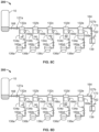
- the measuring chambers 132 a - d are still filled with blood, but the blood from the measuring chamber 132 e has transferred to the mixing chamber 134 e .
- the following changes were made (in comparison to FIG. 8 B ) and/or the following conditions existed: (i) the valves 168 and 170 were closed, (ii) the valves 160 a - e remained closed, (iii) the vents 166 a - d remained closed, (iv) the vent 166 e was opened, and (v) a source of air pressure was applied to the pressure application port 164 .
- the fluidic control process 200 shown in FIG. 8 C includes stop junctions (not shown) between the measuring chamber 132 a - e and the mixing chamber 134 a - e to prevent the flow of blood from the measuring chamber to the mixing chamber unless a sufficient pressure differential between the measuring chamber 132 a - e and the mixing chamber 134 a - e is applied.
- the stop junction prevents leakage of blood from measuring chambers 132 a - d into mixing chambers 166 a - d without opening the vents 166 a - d or applying sufficient pressure to the pressure application port 164 to cause blood to flow through the stop junction.
- the sample handler assembly 400 of the analyzer console 140 also includes the viscoelastic measurement system 480 .
- the viscoelastic measurement system 480 includes the baseplate 302 (e.g., refer to FIG. 10 C ), one or more thromboelastometry assemblies (e.g., thromboelastometry assembly 300 b ), and a linear actuator assembly.
- the one or more thromboelastometry assemblies can each be affixed to the baseplate 302 .
- the linear actuator assembly can be coupled to the baseplate 302 and to the cartridge receiver and clamp 410 . Accordingly, actuation of the linear actuator assembly can translate the baseplate 302 and the cartridge receiver and clamp 410 towards each other or away from each other.
- a linear bearing assembly of the linear actuator can guide the baseplate 302 in a linear path, and stabilize the baseplate 302 , as the baseplate 302 translates towards or away from the cartridge receiver and clamp 410 .
- the analyzer console can unclamp the cartridge at the cessation of the testing.
- cessation may be initiated by a user input to the analyzer console to stop the testing, or by the completion of the test assays, or by the expiration of a time-based parameter.
- the unclamping may be performed, for example, by the horizontal translation of the moveable block sub-assembly. After the unclamping, the cartridge can be removed from the analyzer console.
Landscapes
- Health & Medical Sciences (AREA)
- Life Sciences & Earth Sciences (AREA)
- Engineering & Computer Science (AREA)
- Hematology (AREA)
- Biomedical Technology (AREA)
- Chemical & Material Sciences (AREA)
- Immunology (AREA)
- Molecular Biology (AREA)
- Urology & Nephrology (AREA)
- Physics & Mathematics (AREA)
- Pathology (AREA)
- Food Science & Technology (AREA)
- Medicinal Chemistry (AREA)
- Analytical Chemistry (AREA)
- Biochemistry (AREA)
- General Health & Medical Sciences (AREA)
- General Physics & Mathematics (AREA)
- Biotechnology (AREA)
- Cell Biology (AREA)
- Microbiology (AREA)
- Ecology (AREA)
- Biophysics (AREA)
- Investigating Or Analysing Biological Materials (AREA)
Abstract
Description
Claims (32)
Priority Applications (1)
| Application Number | Priority Date | Filing Date | Title |
|---|---|---|---|
| US16/708,334 US12031993B2 (en) | 2014-09-29 | 2019-12-09 | Blood testing system and method |
Applications Claiming Priority (3)
| Application Number | Priority Date | Filing Date | Title |
|---|---|---|---|
| US14/500,248 US10175225B2 (en) | 2014-09-29 | 2014-09-29 | Blood testing system and method |
| US14/958,878 US10539579B2 (en) | 2014-09-29 | 2015-12-03 | Blood testing system and method |
| US16/708,334 US12031993B2 (en) | 2014-09-29 | 2019-12-09 | Blood testing system and method |
Related Parent Applications (1)
| Application Number | Title | Priority Date | Filing Date |
|---|---|---|---|
| US14/958,878 Division US10539579B2 (en) | 2014-09-29 | 2015-12-03 | Blood testing system and method |
Publications (2)
| Publication Number | Publication Date |
|---|---|
| US20200116742A1 US20200116742A1 (en) | 2020-04-16 |
| US12031993B2 true US12031993B2 (en) | 2024-07-09 |
Family
ID=55584103
Family Applications (2)
| Application Number | Title | Priority Date | Filing Date |
|---|---|---|---|
| US14/958,878 Active 2036-07-13 US10539579B2 (en) | 2014-09-29 | 2015-12-03 | Blood testing system and method |
| US16/708,334 Active 2036-10-17 US12031993B2 (en) | 2014-09-29 | 2019-12-09 | Blood testing system and method |
Family Applications Before (1)
| Application Number | Title | Priority Date | Filing Date |
|---|---|---|---|
| US14/958,878 Active 2036-07-13 US10539579B2 (en) | 2014-09-29 | 2015-12-03 | Blood testing system and method |
Country Status (1)
| Country | Link |
|---|---|
| US (2) | US10539579B2 (en) |
Families Citing this family (14)
| Publication number | Priority date | Publication date | Assignee | Title |
|---|---|---|---|---|
| US8448499B2 (en) | 2008-12-23 | 2013-05-28 | C A Casyso Ag | Cartridge device for a measuring system for measuring viscoelastic characteristics of a sample liquid, a corresponding measuring system, and a corresponding method |
| US10816559B2 (en) | 2014-09-29 | 2020-10-27 | Ca Casyso Ag | Blood testing system and method |
| US10175225B2 (en) | 2014-09-29 | 2019-01-08 | C A Casyso Ag | Blood testing system and method |
| US10288630B2 (en) | 2014-09-29 | 2019-05-14 | C A Casyso Gmbh | Blood testing system and method |
| US9897618B2 (en) | 2014-09-29 | 2018-02-20 | C A Casyso Gmbh | Blood testing system |
| US10539579B2 (en) | 2014-09-29 | 2020-01-21 | C A Casyso Gmbh | Blood testing system and method |
| US10295554B2 (en) | 2015-06-29 | 2019-05-21 | C A Casyso Gmbh | Blood testing system and method |
| EP4062962B1 (en) * | 2015-12-03 | 2023-10-04 | C A Casyso GmbH | Blood testing system and method |
| CN109642909B (en) * | 2016-08-29 | 2022-06-03 | 藤森工业株式会社 | Blood coagulation test device and blood coagulation test method |
| US10473674B2 (en) * | 2016-08-31 | 2019-11-12 | C A Casyso Gmbh | Controlled blood delivery to mixing chamber of a blood testing cartridge |
| US10843185B2 (en) | 2017-07-12 | 2020-11-24 | Ca Casyso Gmbh | Autoplatelet cartridge device |
| EP3971576B1 (en) | 2020-09-21 | 2025-03-19 | Instrumentation Laboratory Company | Detecting and monitoring oral anticoagulants or intravenous direct thrombin inhibitors in a blood sample |
| CN114397467B (en) * | 2022-01-11 | 2024-08-23 | 广州万孚生物技术股份有限公司 | Blood gas analyzer |
| CN115672425B (en) * | 2022-11-07 | 2024-08-06 | 苏州思迈德生物科技有限公司 | Microfluidic chip and detection device for detecting multichannel thrombus elasticity map |
Citations (341)
| Publication number | Priority date | Publication date | Assignee | Title |
|---|---|---|---|---|
| US2555937A (en) | 1949-08-25 | 1951-06-05 | Robert L Rosenthal | Method and apparatus for measuring resistance of blood during clotting |
| US2995425A (en) | 1957-12-24 | 1961-08-08 | S L F Engineering Company | Apparatus for continuously colorimetrically analyzing fluids for chemical components |
| US3714815A (en) | 1970-04-22 | 1973-02-06 | Hellige & Co Gmbh F | Means for simulating the natural flow of blood |
| US3803903A (en) | 1972-03-23 | 1974-04-16 | Du Pont | Apparatus and method for measuring the rheological properties of a fluid |
| US3903903A (en) | 1973-04-09 | 1975-09-09 | Kanegafuchi Chemical Ind | Method and equipment for planting hairs in sheet-form net-like material or thread form body |
| US4112740A (en) | 1977-01-13 | 1978-09-12 | Contraves Ag | Method and apparatus for determining a change of the flow state of flowable substances from its static state to its flowing state or vice verse |
| DE2740932A1 (en) | 1977-04-28 | 1978-11-09 | Elvi Spa | DEVICE FOR DETERMINING THE PARAMETERS OF BLOOD ELASTICITY |
| US4148216A (en) | 1978-01-18 | 1979-04-10 | Do Mau T | Apparatus for determining the viscous behavior of a liquid during coagulation thereof |
| USD260428S (en) | 1979-03-15 | 1981-08-25 | Abbott Laboratories | Cuvette array or the like |
| US4319194A (en) | 1978-10-02 | 1982-03-09 | Burroughs Wellcome Co. | Method of and apparatus for monitoring platelet aggregation and test cell for use in such method and apparatus |
| US4443408A (en) | 1981-07-09 | 1984-04-17 | International Technidyne, Inc. | Apparatus for analyzing the influence of additive reagents upon the coagulation of blood |
| US4558589A (en) | 1984-10-09 | 1985-12-17 | Miles Laboratories, Inc. | Ultrasonic coagulation monitor and method |
| US4599219A (en) | 1982-10-15 | 1986-07-08 | Hemotec, Inc. | Coagulation detection by plunger sensing technique |
| US4671939A (en) | 1981-07-09 | 1987-06-09 | International Technidyne Corp. | Apparatus for analyzing the influence of additive reagents upon the coagulation of blood and related methods |
| JPS62140047A (en) | 1985-12-13 | 1987-06-23 | メトレル―トレド・アクチエンゲゼルシヤフト | Method and device for measuring fluid characteristic of substance |
| US4695956A (en) | 1984-11-01 | 1987-09-22 | Leveen Eric G | Apparatus and method of quantifying hemostasis using oscillations from a transducer immersed in the blood sample |
| US4705756A (en) | 1983-01-26 | 1987-11-10 | University Of Medicine And Dentistry Of New Jersey | Method of determining the existence and/or the monitoring of a pathological condition in a mammal |
| US4752449A (en) | 1982-10-15 | 1988-06-21 | Hemotec, Inc. | Apparatus for coagulation detection by gas flow or plunger sensing techniques |
| US4753776A (en) | 1986-10-29 | 1988-06-28 | Biotrack, Inc. | Blood separation device comprising a filter and a capillary flow pathway exiting the filter |
| US4756884A (en) | 1985-08-05 | 1988-07-12 | Biotrack, Inc. | Capillary flow device |
| US4765180A (en) | 1985-09-03 | 1988-08-23 | Michael Clifton | Viscometer |
| US4767600A (en) | 1984-06-19 | 1988-08-30 | Finbiomedica S.R.L. | Equipment for rapid, automatic chemical-clinical analysis |
| US4814247A (en) | 1983-01-26 | 1989-03-21 | University Of Medicine And Dentistry Of New Jersey | Method for determining the existance and/or the monitoring of a pathological condition in a mammal |
| JPH01140047A (en) | 1987-11-27 | 1989-06-01 | Hitachi Ltd | Method for detecting bulk particles in transparent thin film |
| USD302294S (en) | 1986-10-03 | 1989-07-18 | Biotrack, Inc. | Reagent cartridge for blood analysis |
| US4849340A (en) | 1987-04-03 | 1989-07-18 | Cardiovascular Diagnostics, Inc. | Reaction system element and method for performing prothrombin time assay |
| WO1989006803A1 (en) | 1988-01-14 | 1989-07-27 | Nordisk Gentofte A/S | Apparatus for determination of the coagulation time of a blood sample |
| US4852577A (en) | 1988-04-07 | 1989-08-01 | The United States Of America As Represented By The Department Of Health And Human Services | High speed adaptive ultrasonic phased array imaging system |
| US4868129A (en) | 1987-08-27 | 1989-09-19 | Biotrack Inc. | Apparatus and method for dilution and mixing of liquid samples |
| USD305360S (en) | 1986-07-11 | 1990-01-02 | Beckman Instruments, Inc. | Fluid cartridge for an automated clinical chemical analyzer |
| US4900679A (en) | 1983-01-26 | 1990-02-13 | University Of Medicine And Dentistry Of New Jersey | Method for determining the existence and/or the monitoring of a pathological condition in a mammal and a test kit therefor |
| US4948961A (en) | 1985-08-05 | 1990-08-14 | Biotrack, Inc. | Capillary flow device |
| US4956089A (en) | 1984-05-10 | 1990-09-11 | Stephen Hurst | Forming an end-cap on a filter cartridge |
| US4963498A (en) | 1985-08-05 | 1990-10-16 | Biotrack | Capillary flow device |
| EP0404456A2 (en) | 1989-06-19 | 1990-12-27 | Haemoscope Corporation | Disposable pin and cup with reuseable stem and collar for blood coagulation analyzer |
| US5009316A (en) | 1988-03-29 | 1991-04-23 | Klein David C | Test tube cassette system and cassettes for use therein |
| US5016469A (en) | 1989-09-29 | 1991-05-21 | Sienco, Inc. | Fluid viscoelastic test apparatus and method |
| US5028142A (en) | 1989-04-06 | 1991-07-02 | Biotrack, Inc. | Reciprocal mixer |
| US5056357A (en) | 1987-11-02 | 1991-10-15 | Stephan Dymling | Acoustic method for measuring properties of a mobile medium |
| US5077017A (en) | 1987-11-05 | 1991-12-31 | Biotrack, Inc. | Integrated serial dilution and mixing cartridge |
| US5091304A (en) | 1989-08-21 | 1992-02-25 | International Technidyne Corporation | Whole blood activated partial thromboplastin time test and associated apparatus |
| US5104975A (en) | 1988-07-08 | 1992-04-14 | Cetus Corporation | Compositions for detecting ras gene proteins and cancer therapeutics |
| US5104813A (en) | 1989-04-13 | 1992-04-14 | Biotrack, Inc. | Dilution and mixing cartridge |
| USD327743S (en) | 1989-07-24 | 1992-07-07 | Pb Diagnostic Systems, Inc. | Sample cup holder or similar article |
| US5162237A (en) | 1988-04-11 | 1992-11-10 | Miles Inc. | Reaction cassette for preforming sequential analytical assays by noncentrifugal and noncapillary manipulations |
| US5164598A (en) | 1985-08-05 | 1992-11-17 | Biotrack | Capillary flow device |
| US5169786A (en) | 1989-12-19 | 1992-12-08 | Ortho Diagnostic Systems, Inc. | Method of determining levels of extrinsic and intrinsic clotting factors and protein c |
| GB2257256A (en) | 1991-06-27 | 1993-01-06 | Total Sa | Consistometer for measuring rheological change |
| US5204525A (en) | 1985-08-05 | 1993-04-20 | Biotrack | Capillary flow device |
| US5205159A (en) | 1992-01-17 | 1993-04-27 | Virginia Commonwealth University | Apparatus and method for measuring clot elastic modulus and force development on the same blood sample |
| US5207988A (en) | 1989-07-06 | 1993-05-04 | The Cleveland Clinic Foundation | Apparatus for detecting and quantifying clot lysis and establishing optimum medication and dosages |
| US5223219A (en) | 1992-04-10 | 1993-06-29 | Biotrack, Inc. | Analytical cartridge and system for detecting analytes in liquid samples |
| US5222808A (en) | 1992-04-10 | 1993-06-29 | Biotrack, Inc. | Capillary mixing device |
| US5223227A (en) | 1989-06-19 | 1993-06-29 | Haemoscope Corporation | Disposable pin and cup with reuseable stem and collar for blood coagulation analyzer |
| US5234839A (en) | 1988-07-08 | 1993-08-10 | Cetus Oncology Corporation | Compositions for detecting ras gene proteins and cancer therapeutics |
| US5273517A (en) | 1991-07-09 | 1993-12-28 | Haemonetics Corporation | Blood processing method and apparatus with disposable cassette |
| US5287732A (en) | 1990-10-03 | 1994-02-22 | Toki Sangyo Co., Ltd. | Rotary viscosimeter |
| US5302348A (en) | 1992-12-10 | 1994-04-12 | Itc Corporation | Blood coagulation time test apparatus and method |
| USD347067S (en) | 1991-03-15 | 1994-05-17 | Biotrack, Inc. | Analytical cartridge for testing biological fluids |
| US5331964A (en) | 1993-05-14 | 1994-07-26 | Duke University | Ultrasonic phased array imaging system with high speed adaptive processing using selected elements |
| US5378431A (en) | 1993-06-14 | 1995-01-03 | Becton, Dickinson And Company | Dual pathway clotting enhancer for blood collection tube |
| US5447440A (en) | 1993-10-28 | 1995-09-05 | I-Stat Corporation | Apparatus for assaying viscosity changes in fluid samples and method of conducting same |
| US5473536A (en) | 1994-04-04 | 1995-12-05 | Spacelabs Medical, Inc. | Method and system for customizing the display of patient physiological parameters on a medical monitor |
| US5487387A (en) | 1994-06-03 | 1996-01-30 | Duke University | Method and apparatus for distinguishing between solid masses and fluid-filled cysts |
| US5504011A (en) | 1994-10-21 | 1996-04-02 | International Technidyne Corporation | Portable test apparatus and associated method of performing a blood coagulation test |
| US5531102A (en) | 1994-12-14 | 1996-07-02 | Brookfield Engineering Laboratories, Inc. | Viscometer usable in situ in large reactor vessels |
| WO1996038730A1 (en) | 1995-06-02 | 1996-12-05 | Cdc Technologies, Inc. | Apparatus and method for mixing fluids for analysis |
| US5602037A (en) | 1994-06-30 | 1997-02-11 | Dade International, Inc. | Combination reagent holding and test device |
| US5605154A (en) | 1995-06-06 | 1997-02-25 | Duke University | Two-dimensional phase correction using a deformable ultrasonic transducer array |
| US5606971A (en) | 1995-11-13 | 1997-03-04 | Artann Corporation, A Nj Corp. | Method and device for shear wave elasticity imaging |
| US5629209A (en) | 1995-10-19 | 1997-05-13 | Braun, Sr.; Walter J. | Method and apparatus for detecting viscosity changes in fluids |
| JPH09159596A (en) | 1995-12-05 | 1997-06-20 | Nippon Steel Corp | Viscosity measuring method and device |
| JPH09507580A (en) | 1994-10-19 | 1997-07-29 | カラツィス・アレキサンダー | Device for measuring condensation property of test solution |
| US5655535A (en) | 1996-03-29 | 1997-08-12 | Siemens Medical Systems, Inc. | 3-Dimensional compound ultrasound field of view |
| US5657760A (en) | 1994-05-03 | 1997-08-19 | Board Of Regents, The University Of Texas System | Apparatus and method for noninvasive doppler ultrasound-guided real-time control of tissue damage in thermal therapy |
| US5660993A (en) | 1993-02-18 | 1997-08-26 | Biocircuits Corporation | Disposable device in diagnostic assays |
| US5673699A (en) | 1996-05-31 | 1997-10-07 | Duke University | Method and apparatus for abberation correction in the presence of a distributed aberrator |
| US5731212A (en) | 1994-12-20 | 1998-03-24 | International Technidyne Corporation | Test apparatus and method for testing cuvette accommodated samples |
| US5744898A (en) | 1992-05-14 | 1998-04-28 | Duke University | Ultrasound transducer array with transmitter/receiver integrated circuitry |
| US5763199A (en) | 1994-09-29 | 1998-06-09 | Mount Sinai School Of Medicine Of The City University Of New York | Platelet blockade assay |
| US5777212A (en) | 1996-03-01 | 1998-07-07 | Toki Sangyo Co., Ltd. | Spring relaxation method and rotary viscometer for measuring rheological flow properties of a liquid sample by the method |
| US5788928A (en) | 1995-07-07 | 1998-08-04 | Chiron Diagnostics Corporation | Reagent handling system and reagent pack for use therein |
| US5810731A (en) | 1995-11-13 | 1998-09-22 | Artann Laboratories | Method and apparatus for elasticity imaging using remotely induced shear wave |
| US5854076A (en) | 1994-06-30 | 1998-12-29 | Dade International Inc. | Method for testing coagulation of blood through bioactive porous partition members |
| US5854423A (en) | 1996-03-20 | 1998-12-29 | Venegas; Jose G. | Apparatus and method for assessment of visco-elasticity and shear adherence strength properties of blood clots |
| US5888826A (en) | 1994-06-30 | 1999-03-30 | Dade Behring Inc. | Combination reagent holding and test device |
| US5899861A (en) | 1995-03-31 | 1999-05-04 | Siemens Medical Systems, Inc. | 3-dimensional volume by aggregating ultrasound fields of view |
| US5902937A (en) | 1997-10-01 | 1999-05-11 | Baxter International Inc. | In vitro tissue testing system |
| US5922551A (en) | 1997-03-20 | 1999-07-13 | Accumetrics, Inc. | Agglutrimetric platelet binding assays in blood |
| US5922591A (en) | 1995-06-29 | 1999-07-13 | Affymetrix, Inc. | Integrated nucleic acid diagnostic device |
| US5921928A (en) | 1996-12-05 | 1999-07-13 | Mayo Foundation For Medical Education And Research | Acoustic force generation by amplitude modulating a sonic beam |
| US5952560A (en) | 1994-11-09 | 1999-09-14 | Commonwealth Scientific And Industrial Research Organisation | Particle property measurement |
| US6012712A (en) | 1998-03-20 | 2000-01-11 | Kurt Manufacturing Company, Inc. | Double vise with self-setting clamping with the same or different size workpieces |
| US6016712A (en) | 1997-09-18 | 2000-01-25 | Accumetrics | Device for receiving and processing a sample |
| US6033546A (en) | 1994-08-01 | 2000-03-07 | Lockheed Martin Energy Research Corporation | Apparatus and method for performing microfluidic manipulations for chemical analysis and synthesis |
| US6039691A (en) | 1997-06-02 | 2000-03-21 | Duke University | Kinetic acoustic ocular examination apparatus and method |
| US6046051A (en) | 1997-06-27 | 2000-04-04 | Hemosense, Inc. | Method and device for measuring blood coagulation or lysis by viscosity changes |
| US6066243A (en) | 1997-07-22 | 2000-05-23 | Diametrics Medical, Inc. | Portable immediate response medical analyzer having multiple testing modules |
| US6083159A (en) | 1995-05-22 | 2000-07-04 | Ths International, Inc. | Methods and devices for providing acoustic hemostasis |
| US6114135A (en) | 1991-11-08 | 2000-09-05 | Goldstein; Sheldon | Multiple coagulation test system and method of using a multiple coagulation test system |
| US6117081A (en) | 1998-10-01 | 2000-09-12 | Atl Ultrasound, Inc. | Method for correcting blurring of spatially compounded ultrasonic diagnostic images |
| US6135957A (en) | 1998-01-23 | 2000-10-24 | U.S. Philips Corporation | Method of and apparatus for echographic determination of the viscosity and the pressure gradient in a blood vessel |
| US6200532B1 (en) | 1998-11-20 | 2001-03-13 | Akzo Nobel Nv | Devices and method for performing blood coagulation assays by piezoelectric sensing |
| US6213950B1 (en) | 1996-11-01 | 2001-04-10 | Endosonics Corporation | Measurement of volumetric fluid flow and its velocity profile |
| US6221672B1 (en) | 1996-04-30 | 2001-04-24 | Medtronic, Inc. | Method for determining platelet inhibitor response |
| US6225126B1 (en) | 1999-02-22 | 2001-05-01 | Haemoscope Corporation | Method and apparatus for measuring hemostasis |
| USRE37171E1 (en) | 1988-02-10 | 2001-05-08 | Curwood, Inc. | Easy open package |
| US6232127B1 (en) | 1997-04-30 | 2001-05-15 | Medtronic, Inc. | Platelet function evaluation technique for citrated whole blood |
| US6242267B1 (en) | 1996-03-19 | 2001-06-05 | University Of Utah Research Foundation | Oscillation apparatus and methods for multi-analyte homogeneous fluoro-immunoassays |
| US6264609B1 (en) | 1999-09-15 | 2001-07-24 | Wake Forest University | Ultrasound apparatus and method for tissue characterization |
| US6270459B1 (en) | 1998-05-26 | 2001-08-07 | The Board Of Regents Of The University Of Texas System | Method for estimating and imaging of transverse displacements, transverse strains and strain ratios |
| US6277074B1 (en) | 1998-10-02 | 2001-08-21 | University Of Kansas Medical Center | Method and apparatus for motion estimation within biological tissue |
| US6283917B1 (en) | 1998-10-01 | 2001-09-04 | Atl Ultrasound | Ultrasonic diagnostic imaging system with blurring corrected spatial compounding |
| JP2001258868A (en) | 2000-03-15 | 2001-09-25 | Jun Kikuchi | Method and device for blood analysis |
| US6318191B1 (en) | 1998-06-24 | 2001-11-20 | Chen & Chen, Llc | Fluid sample testing system |
| US20010046685A1 (en) | 1999-05-28 | 2001-11-29 | Moskowitz Keith A. | Control for methods for determining platelet count and platelet function |
| EP1162457A2 (en) | 2000-06-09 | 2001-12-12 | GOLDSTEIN, Sheldon | Multiple coagulation test system and method of using a multiple coagulation test system |
| US20020040187A1 (en) | 2000-07-20 | 2002-04-04 | Alam Sheikh Kaisar | Methods for estimating tissue strain |
| US6371912B1 (en) | 2000-04-05 | 2002-04-16 | Duke University | Method and apparatus for the identification and characterization of regions of altered stiffness |
| US6398956B1 (en) | 1999-05-28 | 2002-06-04 | Bio/Data Corporation | Method and apparatus for directly sampling a fluid for microfiltration |
| US6402704B1 (en) | 2000-04-18 | 2002-06-11 | Sonexxus Incorporated | Prothrombin test apparatus for home use |
| US6403381B1 (en) | 1998-06-08 | 2002-06-11 | University Of Vermont And State Agriculture College | Inhibition of coagulation in blood and blood products |
| US20020081741A1 (en) | 2000-12-21 | 2002-06-27 | Walter J. Braun, Sr. | Apparatus for testing liquid/reagent mixtures |
| US6412344B1 (en) | 1999-11-15 | 2002-07-02 | Rosemount Aerospace Inc. | Fluid level sensor with dry couplant |
| US6413782B1 (en) | 1996-06-28 | 2002-07-02 | Caliper Technologies Corp. | Methods of manufacturing high-throughput screening systems |
| WO2002063273A2 (en) | 2001-01-19 | 2002-08-15 | Chow Herbert S | Device and method for evaluating platelets |
| US6436722B1 (en) | 2000-04-18 | 2002-08-20 | Idexx Laboratories, Inc. | Device and method for integrated diagnostics with multiple independent flow paths |
| US6448024B1 (en) | 2000-10-03 | 2002-09-10 | Roche Diagnostics Corporation | Method, reagent, cartridge, and device for determining fibrinogen |
| US6451610B1 (en) | 1999-04-14 | 2002-09-17 | International Technidyne Corporation | Method and apparatus for coagulation based assays |
| US6454714B1 (en) | 2000-10-20 | 2002-09-24 | Koninklijke Philips Electronics N.V. | Ultrasonic harmonic flash suppression |
| US20020177958A1 (en) | 2000-02-10 | 2002-11-28 | I-Stat Corporation | System, method and computer implemented process for assaying coagulation in fluid samples |
| US6494834B2 (en) | 2000-03-17 | 2002-12-17 | The Board Of Regents Of The University Of Texas System | Power spectral strain estimators in elastography |
| US20030013958A1 (en) | 2001-07-10 | 2003-01-16 | Assaf Govari | Location sensing with real-time ultrasound imaging |
| US6508768B1 (en) | 2000-11-22 | 2003-01-21 | University Of Kansas Medical Center | Ultrasonic elasticity imaging |
| DE10135569A1 (en) | 2001-07-20 | 2003-02-06 | Bartels Mikrotechnik Gmbh | Micromechanical component used in production of micro-structured pump and/or nozzle has hollow chamber for gaseous and/or liquid medium, and layers made from material having different elastic coefficients |
| US6535835B1 (en) | 2000-01-31 | 2003-03-18 | Ge Medical Systems Global Technology Company, Llc | Angle independent ultrasound volume flow measurement |
| US20030073244A1 (en) | 2001-10-10 | 2003-04-17 | Eli Cohen | Method and apparatus for diagnosing hemostasis |
| US6573104B2 (en) | 2001-05-10 | 2003-06-03 | Hemodyne, Incorporated | Disposable cup and cone used in blood analysis instrumentation |
| US20030105398A1 (en) | 2001-12-03 | 2003-06-05 | Insightec-Txsonics Ltd. | Apparatus, systems, and methods for measuring power output of an ultrasound transducer |
| US20030113929A1 (en) | 2000-04-28 | 2003-06-19 | Baugh Robert F. | Method and device for testing a sample of fresh whole blood |
| US6613573B1 (en) | 1999-02-22 | 2003-09-02 | Haemoscope Corporation | Method and apparatus for monitoring anti-platelet agents |
| US20030170883A1 (en) | 2002-03-11 | 2003-09-11 | Corning Incorporated | Microplate manufactured from a thermally conductive material and methods for making and using such microplates |
| EP1347058A2 (en) | 2002-03-21 | 2003-09-24 | Roche Diagnostics GmbH | Electrochemical biosensor with connector windows |
| US6632678B2 (en) | 2001-01-03 | 2003-10-14 | Sienco, Inc. | Method for performing activated clotting time test with reduced sensitivity to the presence of aprotinin and for assessing aprotinin sensitivity |
| USD481133S1 (en) | 2002-04-18 | 2003-10-21 | Instrumentation Laboratory Company | Sample well-strip for an automated sample analyzer |
| US20030199082A1 (en) | 2002-04-15 | 2003-10-23 | James Miller | Thermally-conductive biological assay trays |
| US20030204141A1 (en) | 2002-04-30 | 2003-10-30 | Siemens Medical Solutions Usa, Inc. | Ultrasound drug delivery enhancement and imaging systems and methods |
| USD482454S1 (en) | 2002-09-20 | 2003-11-18 | Dade Behring Inc. | Multi-compartment reagent container for containing reagents |
| EP1367392A1 (en) | 2002-05-31 | 2003-12-03 | F.Hoffmann-La Roche Ag | Method and device for measuring blood gas parameters |
| US6662031B1 (en) | 1998-05-18 | 2003-12-09 | Abbott Laboratoies | Method and device for the noninvasive determination of hemoglobin and hematocrit |
| US6670133B2 (en) | 1997-04-04 | 2003-12-30 | Caliper Technologies Corp. | Microfluidic device for sequencing by hybridization |
| US6687625B2 (en) | 2002-04-22 | 2004-02-03 | The Board Of Regents Of The University Of Texas System | Method and apparatus for feature tracking strain estimation for elastography |
| US6692439B1 (en) | 1999-07-07 | 2004-02-17 | University Of Virginia Patent Foundation | Angular scatter imaging system using translating apertures and method thereof |
| US6699718B1 (en) | 1999-09-03 | 2004-03-02 | Roche Diagnostics Corporation | Method, reagent and test cartridge for determining clotting time |
| EP1394546A1 (en) | 2002-08-30 | 2004-03-03 | Lifescan, Inc. | Method and system for determining the acceptability of signal data collected from a prothrombin time test strip |
| US20040053351A1 (en) | 2000-10-27 | 2004-03-18 | Fischer Timothy J. | Method of determining global coagulability and hemostatic potential |
| US20040065143A1 (en) | 2002-10-03 | 2004-04-08 | Husher Frederick K. | Apparatus and method for analyzing a liquid in a capillary tube of a hematology instrument |
| US20040068184A1 (en) | 2002-10-07 | 2004-04-08 | Trahey Gregg E. | Methods, systems, and computer program products for imaging using virtual extended shear wave sources |
| US20040072278A1 (en) | 2002-04-01 | 2004-04-15 | Fluidigm Corporation | Microfluidic particle-analysis systems |
| US20040072357A1 (en) | 2000-12-19 | 2004-04-15 | Matthias Stiene | Device for measuring blood coagulation and method thereof |
| US20040076546A1 (en) | 2002-10-18 | 2004-04-22 | Bissett Brian D. | Automated kinetic solubility assay apparatus and method |
| US6726629B1 (en) | 1998-01-16 | 2004-04-27 | Acuson Corporation | Ultrasound contrast imaging |
| US20040088317A1 (en) | 2002-07-12 | 2004-05-06 | Allan Fabrick | Methods, system, software and graphical user interface for presenting medical information |
| US20040089616A1 (en) | 1997-05-23 | 2004-05-13 | Gregory Kellogg | Devices and methods for using centripetal acceleration to drive fluid movement in a microfluidics system for performing biological fluid assays |
| US6750053B1 (en) | 1999-11-15 | 2004-06-15 | I-Stat Corporation | Apparatus and method for assaying coagulation in fluid samples |
| US20040131500A1 (en) | 2002-01-18 | 2004-07-08 | Chow Herbert S. | Device and method for evaluating platelets |
| US20040167403A1 (en) | 2000-04-05 | 2004-08-26 | Nightingale Kathryn R. | Methods, systems, and computer program products for ultrasound measurements using receive mode parallel processing |
| US6787363B2 (en) | 1999-02-22 | 2004-09-07 | Haemoscope Corporation | Method and apparatus for hemostasis and blood management |
| US20040189311A1 (en) | 2002-12-26 | 2004-09-30 | Glezer Eli N. | Assay cartridges and methods of using the same |
| US20040203163A1 (en) | 2003-04-08 | 2004-10-14 | Eli Cohen | Method and apparatus for monitoring hemostasis in connection with artificial surface devices |
| US20040214337A1 (en) | 2003-04-24 | 2004-10-28 | Hans Kautzky | Hemostasis analyzer and method |
| US6838055B2 (en) | 2000-11-20 | 2005-01-04 | Minolta Co., Ltd. | Microchip |
| US20050004463A1 (en) | 2003-04-09 | 2005-01-06 | Shigao Chen | Method and apparatus for shear property characterization from resonance induced by oscillatory radiation force |
| US20050015001A1 (en) | 2003-04-16 | 2005-01-20 | Lec Ryszard M. | Acoustic blood analyzer for assessing blood properties |
| US20050053305A1 (en) | 2003-09-10 | 2005-03-10 | Yadong Li | Systems and methods for implementing a speckle reduction filter |
| WO2005026690A2 (en) | 2003-09-10 | 2005-03-24 | I-Stat Corporation | Immunoassay device with improved sample closure |
| US20050123447A1 (en) | 2001-12-14 | 2005-06-09 | Masufumi Koike | Sample measuring device |
| US20050136541A1 (en) | 2003-12-23 | 2005-06-23 | Dade Behring Marburg Gmbh | Cartridge for monitoring the function of a device for testing blood platelet function, method for function monitoring, and use of a test fluid |
| JP2005164296A (en) | 2003-11-28 | 2005-06-23 | Advance Co Ltd | Biocomponent diagnostic system |
| US20050148899A1 (en) | 2003-10-22 | 2005-07-07 | Walker William F. | Method and apparatus for characterization of clot formation |
| US20050164373A1 (en) | 2004-01-22 | 2005-07-28 | Oldham Mark F. | Diffusion-aided loading system for microfluidic devices |
| US6942836B2 (en) | 2001-10-16 | 2005-09-13 | Applera Corporation | System for filling substrate chambers with liquid |
| US20050215901A1 (en) | 2004-01-20 | 2005-09-29 | Anderson Thomas L | Interface for use between medical instrumentation and a patient |
| US20050216987P1 (en) | 2004-03-26 | 2005-09-29 | Yasuyuki Murakami | Calibrachoa plant named 'sunbelhopi' |
| US6951127B1 (en) | 2003-03-31 | 2005-10-04 | Hongfeng Bi | Digital viscometer with non contact distance sensor |
| US20050220668A1 (en) | 2004-04-06 | 2005-10-06 | Bio/Data Corporation | Disposable test device with sample volume measurement and mixing methods |
| US20050233460A1 (en) | 2004-02-27 | 2005-10-20 | Clague Cynthia T | Blood coagulation test cartridge, system, and method |
| US20050233466A1 (en) | 2004-04-19 | 2005-10-20 | Wright David W | Blood coagulation test cartridge, system, and method |
| JP2005534895A (en) | 2002-06-11 | 2005-11-17 | ケムパック エイ/エス | Lysis reagents, cartridges and automated electronic cell counters for simultaneous counting of different types of white blood cells |
| EP1627725A2 (en) | 2004-08-12 | 2006-02-22 | Pentapharm AG | Method of treating the surface of a medical device for blood coagulation diagnosis, and such a device |
| CN1816306A (en) | 2003-01-15 | 2006-08-09 | 萨鲁特伦股份有限公司 | Ultrasonic monitor for measuring heart and pulse rates |
| WO2006091650A2 (en) | 2005-02-22 | 2006-08-31 | Jeffrey Valk | Balanced physiological monitoring and treatment system |
| CN1853104A (en) | 2003-08-05 | 2006-10-25 | 希缪司构普公司 | Protocol and apparatus for determining heparin-induced thrombocytopenia |
| US7132078B2 (en) | 2000-07-31 | 2006-11-07 | Cambridge Life Sciences Plc | Assay apparatus |
| WO2006126290A1 (en) | 2005-05-23 | 2006-11-30 | Jun Kawasaki | Method for testing efficacy of antithrombotic agent |
| WO2006137334A1 (en) | 2005-06-23 | 2006-12-28 | Arkray, Inc. | Analytical implement |
| US20070038095A1 (en) | 2003-10-03 | 2007-02-15 | Greenleaf James F | Ultrasound vibrometry |
| US7179652B2 (en) | 1999-02-22 | 2007-02-20 | Haemoscope Corporation | Protocol for monitoring platelet inhibition |
| US20070059208A1 (en) | 2005-09-14 | 2007-03-15 | Applera Corporation | Fluid processing device and integration with sample preparation processes |
| US20070059840A1 (en) | 2005-05-16 | 2007-03-15 | Haemoscope Corporation | Hemostasis Analysis Device and Method |
| US7192726B1 (en) | 1999-08-13 | 2007-03-20 | Hemodyne, Inc. | Method of using platelet contractile force and whole blood clot elastic modulus as clinical markers |
| US20070078631A1 (en) | 2005-09-27 | 2007-04-05 | Sysmex Corporation | Sample analyzer, processing computer for sample analysis, method of displaying operation screen of sample analyzer and computer program product for processing computer for sample analysis |
| US7202048B2 (en) | 2002-04-04 | 2007-04-10 | Hemodyne, Inc. | Onset of force development as a marker of thrombin generation |
| US7205115B2 (en) | 2005-04-28 | 2007-04-17 | Accumetrics, Inc. | Method and system for stabilization of arachidonic acid for use in platelet function assay |
| WO2007047961A2 (en) | 2005-10-20 | 2007-04-26 | Haemoscope Corporation | Hemostasis analyzer and method |
| US20070099290A1 (en) | 2003-09-02 | 2007-05-03 | Kazuhiro Iida | Customizable chip and method of manufacturing the same |
| US20070105236A1 (en) | 2003-11-29 | 2007-05-10 | Digital Bio Technology | Method of examining blood type and apparatus for examining blood type using the method |
| CN1985168A (en) | 2004-05-14 | 2007-06-20 | 霍尼韦尔国际公司 | Portable sample analyzer with removable cartridge |
| US20070140902A1 (en) | 2003-12-16 | 2007-06-21 | Andreas Calatzis | Cartridge device for blood analysis |
| JP2007517221A (en) | 2003-12-30 | 2007-06-28 | スリーエム イノベイティブ プロパティズ カンパニー | Detection cartridge, module, system, and method |
| US7247488B2 (en) | 2003-05-06 | 2007-07-24 | Medtronic, Inc. | Method and kit for testing a multi-channel blood assay cartridge |
| US20070184508A1 (en) | 1999-02-22 | 2007-08-09 | Haemoscope Corporation | Method of Evaluating Patient Hemostasis |
| US7258411B2 (en) | 2002-12-30 | 2007-08-21 | Lexmark International, Inc. | Method of informing a user of end of life of a consumable for an ink jet printer |
| CN101035479A (en) | 2004-07-07 | 2007-09-12 | 塞隆医疗设备公司 | Bipolar coagulation electrode |
| US20070243105A1 (en) | 2004-02-09 | 2007-10-18 | Michael Kratzer | Throughflow Device for Measuring Platelet Function of Primary Hemostasis, Aggregation and/or Coagulation and/or Viscosity of Blood |
| US20070243632A1 (en) | 2003-07-08 | 2007-10-18 | Coller Barry S | Methods for measuring platelet reactivity of patients that have received drug eluting stents |
| US20070259348A1 (en) | 2005-05-03 | 2007-11-08 | Handylab, Inc. | Lyophilized pellets |
| US20070266778A1 (en) | 2003-11-26 | 2007-11-22 | Corey Francis S | Method and Apparatus for Ultrasonic Determination of Hematocrit and Hemoglobin Concentrations |
| US20070276236A1 (en) | 2003-12-16 | 2007-11-29 | Koninklijke Philips Electronics N.V. | Ultrasonic diagnostic imaging system with automatic control of penetration, resolution and frame rate |
| US20080026476A1 (en) | 2004-05-20 | 2008-01-31 | Steven Howell | Device and Method for Detecting Blood Coagulation |
| JP2008503722A (en) | 2004-06-17 | 2008-02-07 | マイクロニクス, インコーポレイテッド | Microfluidic devices for fluid manipulation and analysis |
| US20080038828A1 (en) | 1999-02-22 | 2008-02-14 | Haemoscope Corporation | Protocol for Monitoring Direct Thrombin Inhibition |
| EP1901065A1 (en) | 2006-09-14 | 2008-03-19 | Hemosense INC | Device and method for measuring properties of a sample |
| CN101195112A (en) | 2006-12-06 | 2008-06-11 | 北京北方微电子基地设备工艺研究中心有限责任公司 | Gas injection apparatus |
| WO2008075181A2 (en) | 2006-12-19 | 2008-06-26 | C A Casyso Ag | Apparatus and method for measuring the coagulation characteristics of a test liquid |
| US20080160500A1 (en) | 2004-12-24 | 2008-07-03 | Inverness Medical Switzerland Gmbh | Low volume assay apparatus and method |
| WO2008093216A1 (en) | 2007-02-01 | 2008-08-07 | Dsm Ip Assets B.V. | Diagnostic composition and its use in the determination of coagulation characteristics of a test liquid |
| US20080194041A1 (en) | 2006-03-31 | 2008-08-14 | Guirguis Raouf A | Integrated device for analyte, testing, confirmation, and donor identity verification |
| US20080194967A1 (en) | 2007-02-08 | 2008-08-14 | Sliwa John W | High intensity focused ultrasound transducer with acoustic lens |
| US7412877B1 (en) | 2005-10-24 | 2008-08-19 | Hongfeng Bi | High pressure viscometer with chamber preventing sample contamination |
| US20080200343A1 (en) | 2007-02-15 | 2008-08-21 | Clinical Microsensors, Inc, Dba Osmetech Molecular Diagnostics | Fluidics Devices |
| US20080227217A1 (en) | 2005-11-01 | 2008-09-18 | Matsushita Electric Industrial Co., Ltd. | Sample-liquid analysis disc and method for analyzing sample mixture liquid |
| US20080249408A1 (en) | 2007-02-09 | 2008-10-09 | Palmeri Mark L | Methods, Systems and Computer Program Products for Ultrasound Shear Wave Velocity Estimation and Shear Modulus Reconstruction |
| US20080251383A1 (en) | 2005-08-23 | 2008-10-16 | Zymera, Inc. | Microfluidic Liquid Stream Configuration System |
| US7439069B2 (en) | 2004-02-27 | 2008-10-21 | Nippoldt Douglas D | Blood coagulation test cartridge, system, and method |
| US20080261261A1 (en) | 2006-03-31 | 2008-10-23 | Kmg2 Sensors Corporation | System/unit and method employing a plurality of magnetoelastic sensor elements for automatically quantifying parameters of whole blood and platelet-rich plasma |
| CN101301632A (en) | 2004-11-10 | 2008-11-12 | 横河电机株式会社 | Chemical reaction cartridge, its manufacturing method and chemical reaction cartridge driving system |
| US20080280285A1 (en) | 2005-05-11 | 2008-11-13 | Chen Zongyuan G | Systems and Methods For Testing using Microfluidic Chips |
| US20080297169A1 (en) | 2007-05-31 | 2008-12-04 | Greenquist Alfred C | Particle Fraction Determination of A Sample |
| US20080299587A1 (en) | 2007-05-03 | 2008-12-04 | Dennis Durbin | Methods of measuring inhibition of platelet aggregation by thrombin receptor antagonists |
| JP2008302322A (en) | 2007-06-08 | 2008-12-18 | Arkray Inc | Liquid agitation method, and cartridge and liquid agitation system used for it |
| US20090130645A1 (en) | 2007-11-21 | 2009-05-21 | Axel Schubert | Method for assessing the fibrinogen contribution in coagulation |
| WO2009073851A1 (en) | 2007-12-07 | 2009-06-11 | Sheldon Goldstein | Multiple coagulation test cartridge and method of using same |
| US20090181411A1 (en) | 2006-06-23 | 2009-07-16 | Micronics, Inc. | Methods and devices for microfluidic point-of-care immunoassays |
| US7595169B2 (en) | 2005-04-27 | 2009-09-29 | Accumetrics, Inc. | Method for determining percent platelet aggregation |
| CN101563562A (en) | 2006-12-19 | 2009-10-21 | 皇家飞利浦电子股份有限公司 | Micro fluidic device |
| US20090269837A1 (en) | 2003-03-01 | 2009-10-29 | The Trustees Of Boston University | System for assessing the efficacy of stored red blood cells using microvascular networks |
| US20090305315A1 (en) | 2008-06-09 | 2009-12-10 | Kent Raphael Gandola | Hubbed dual cannula device for closed container sampling systems |
| US20100056383A1 (en) | 2006-11-15 | 2010-03-04 | Ririe Kirk M | High density self-contained biological analysis |
| JP2010078575A (en) | 2008-09-29 | 2010-04-08 | Shimadzu Corp | Reaction vessel processor |
| US20100154520A1 (en) | 2008-12-23 | 2010-06-24 | Axel Schubert | cartridge device for a measuring system for measuring viscoelastic characteristics of a sample liquid, a corresponding measuring system, and a corresponding method |
| US7745223B2 (en) | 2004-08-12 | 2010-06-29 | C A Casyso Ag | Device with novel and improved surface properties |
| EP2202517A1 (en) | 2008-12-23 | 2010-06-30 | C A Casyso AG | A cartridge device for a measuring system for measuring viscoelastic characteristics of a sample liquid,a corresponding measuring system, and a corresponding method |
| EP2208996A1 (en) | 2009-01-16 | 2010-07-21 | C A Casyso AG | A measuring unit for measuring characteristics of a sample liquid, in particular viscoelastic characteristics of a blood sample |
| US20100184201A1 (en) | 2009-01-16 | 2010-07-22 | Axel Schubert | Measuring unit for measuring characteristics of a sample liquid, in particular viscoelastic characteristics of a blood sample |
| US7790362B2 (en) | 2003-07-08 | 2010-09-07 | Accumetrics, Inc. | Controlled platelet activation to monitor therapy of ADP antagonists |
| US20100274130A1 (en) | 2007-12-21 | 2010-10-28 | Koninklijke Philips Electronics N.V. | Systems and methods for tracking and guiding high intensity focused ultrasound beams |
| JP2010266453A (en) | 2002-12-19 | 2010-11-25 | Bayer Healthcare Llc | Method and apparatus for splitting specimen into multiple channels of microfluidic device |
| US20100294767A1 (en) | 2007-11-06 | 2010-11-25 | Pont Emballage | Container of the type comprising a receptacle and a hinged lid |
| US7842234B2 (en) | 2002-12-02 | 2010-11-30 | Epocal Inc. | Diagnostic devices incorporating fluidics and methods of manufacture |
| US7897114B2 (en) | 2007-12-21 | 2011-03-01 | Corning Incorporated | Microreactor assembly incorporating interconnect backbone |
| US7912661B2 (en) | 2006-03-31 | 2011-03-22 | Kmg2 Sensors Corporation | Impedance analysis technique for frequency domain characterization of magnetoelastic sensor element by measuring steady-state vibration of element while undergoing constant sine-wave excitation |
| WO2011035162A1 (en) | 2009-09-17 | 2011-03-24 | University Of Virginia Patent Foundation | Ultrasound-based method and related system to evaluate hemostatic function of whole blood |
| US7939288B2 (en) | 2005-02-08 | 2011-05-10 | Csl Behring Gmbh | Method for differentiating between factor XIII deficiency states and fibrinogen deficiency states by means of thrombelastographic techniques |
| US7938573B2 (en) | 2005-09-02 | 2011-05-10 | Genefluidics, Inc. | Cartridge having variable volume reservoirs |
| US7951606B2 (en) | 2007-01-12 | 2011-05-31 | Nova Biomedical Corporation | Bilirubin sensor |
| US7959875B2 (en) | 2006-01-19 | 2011-06-14 | Rheonix, Inc. | Microfluidic chips and assay systems |
| US20110151491A1 (en) | 2009-12-18 | 2011-06-23 | Entegrion, Inc. | Portable Coagulation Monitoring Device and Method of Assessing Coagulation Response |
| US7972271B2 (en) | 2003-10-28 | 2011-07-05 | The Board Of Trustees Of The Leland Stanford Junior University | Apparatus and method for phased subarray imaging |
| US20110201099A1 (en) | 2009-12-07 | 2011-08-18 | Meso Scale Technologies, Llc. | Assay Cartridges and Methods of Using the Same |
| US8003401B2 (en) | 1998-07-17 | 2011-08-23 | Alertis Medical As | Carbon dioxide sensor and method of determining partial pressure of carbon dioxide |
| JP2011174952A (en) | 2005-08-19 | 2011-09-08 | Panasonic Corp | Device for analysis and analyzer using this |
| US8017382B2 (en) | 2002-03-05 | 2011-09-13 | Abbott Point Of Care Inc. | Apparatus and methods for analyte measurement and immunoassay |
| USD645973S1 (en) | 2010-11-22 | 2011-09-27 | Beckman Coulter, Inc. | Reagent cartridge for holding reagents in a chemistry analyzer |
| WO2011117017A1 (en) | 2010-03-24 | 2011-09-29 | C A Casyso Ag | Method and apparatus for determining at least one evaluation parameter of at least one blood sample |
| WO2011120556A1 (en) | 2010-03-30 | 2011-10-06 | C A Casyso Ag | Composition for the determination of coagulation characteristics of a test liquid |
| US20110252352A1 (en) | 2010-04-08 | 2011-10-13 | Hemosonics Llc | Hemostatic Parameter Display |
| US8058023B2 (en) | 2005-03-01 | 2011-11-15 | Paul A. Gurbel | Assessment of cardiac health and thrombotic risk in a patient |
| US8062883B2 (en) | 1996-04-03 | 2011-11-22 | Applied Biosystems, Llc | Device and method for multiple analyte detection |
| US8084272B2 (en) | 2009-03-25 | 2011-12-27 | Abbott Point Of Care Inc. | Amelioration of heterophile antibody immunosensor interference |
| US20120084022A1 (en) | 2010-10-01 | 2012-04-05 | The Board Of Trustees Of The Leland Stanford Junior University | Enhanced Microfluidic Electromagnetic Measurements |
| US8168442B2 (en) | 1999-05-28 | 2012-05-01 | Cepheid | Cartridge for conducting a chemical reaction |
| US8202492B2 (en) | 2007-05-04 | 2012-06-19 | Opko Diagnostics, Llc | Fluidic connectors and microfluidic systems |
| US8216526B2 (en) | 2008-06-17 | 2012-07-10 | The United States of America, as represented by the Secretary of Commerce, The National Institute of Standards and Technology | Method and device for generating diffusive gradients in a microfluidic chamber |
| US8238182B2 (en) | 2009-09-15 | 2012-08-07 | Elpida Memory, Inc. | Semiconductor device and data processing system comprising semiconductor device |
| US20120232803A1 (en) | 2011-02-15 | 2012-09-13 | Hemosonics Llc | Characterization of blood hemostasis and oxygen transport parameters |
| US20120244392A1 (en) | 2011-03-22 | 2012-09-27 | Enerdel, Inc. | Battery pack support with thermal control |
| US20120252127A1 (en) | 2011-04-01 | 2012-10-04 | Spectral Sciences, Inc. | Optical Blood Coagulation Monitor and Method |
| US20120294767A1 (en) | 2011-05-19 | 2012-11-22 | Hemosonics Llc | Portable hemostasis analyzer |
| US20120329082A1 (en) | 2011-02-15 | 2012-12-27 | Hemosonics Llc | Devices, Systems and Methods For Evaluation of Hemostasis |
| US8431413B2 (en) | 2002-02-25 | 2013-04-30 | Cepheid | Fluid processing and control |
| US20130137172A1 (en) | 2009-05-15 | 2013-05-30 | BioFire Diagnostics, Inc. f/k/a Idaho Technology, Inc. | High density self-contained biological analysis |
| CN103175950A (en) | 2011-12-20 | 2013-06-26 | 中国科学院深圳先进技术研究院 | Hemocyte analysis chip and system for using chip thereof |
| CN103170377A (en) | 2011-12-20 | 2013-06-26 | 中国科学院深圳先进技术研究院 | Hemocyte analysis chip and system for using chip thereof |
| CN103217401A (en) | 2011-12-27 | 2013-07-24 | 霍尼韦尔国际公司 | Disposable cartridge for fluid analysis |
| US8548759B2 (en) | 2009-11-06 | 2013-10-01 | University Of Virginia Patent Foundation | Methods, apparatus, or systems for characterizing physical property in non-biomaterial or bio-material |
| US20130270113A1 (en) | 2012-04-11 | 2013-10-17 | Chuan-Hsing HUANG | Electrochemical strip and manufacturing method thereof |
| WO2013172003A1 (en) | 2012-05-16 | 2013-11-21 | パナソニック株式会社 | Organism detection chip and organism detection device provided therewith |
| WO2013173524A2 (en) | 2012-05-15 | 2013-11-21 | Wellstat Diagnostics, Llc | Clinical diagnostic system including instrument and cartridge |
| US8591829B2 (en) | 2008-12-18 | 2013-11-26 | Opko Diagnostics, Llc | Reagent storage in microfluidic systems and related articles and methods |
| US8591448B2 (en) | 2009-05-13 | 2013-11-26 | Haemonetics Corporation | Pressure monitoring within a fluid cassette |
| JP2014010109A (en) | 2012-07-02 | 2014-01-20 | Sony Corp | Microchip for nucleic acid amplification reaction |
| US8709787B2 (en) | 2006-11-14 | 2014-04-29 | Handylab, Inc. | Microfluidic cartridge and method of using same |
| US8765062B2 (en) | 2010-04-16 | 2014-07-01 | Opko Diagnostics, Llc | Systems and devices for analysis of samples |
| WO2014103744A1 (en) | 2012-12-26 | 2014-07-03 | 株式会社 日立ハイテクノロジーズ | Automatic analyzer |
| WO2014115478A1 (en) | 2013-01-28 | 2014-07-31 | ソニー株式会社 | Impedance measuring device for biological samples and impedance measuring system for biological samples |
| US20140271409A1 (en) | 2013-03-14 | 2014-09-18 | Gen-Probe Incorporated | Fluid cartridge |
| DE202014002289U1 (en) | 2013-03-15 | 2014-09-24 | Coramed Technologies, Llc | Device and cartridge for determining blood clotting |
| WO2014162285A1 (en) | 2013-04-03 | 2014-10-09 | Universita' Degli Studi Di Udine | Apparatus for analyzing the process of formation of aggregates in a biological fluid and corresponding method of analysis |
| WO2014172243A1 (en) | 2013-04-15 | 2014-10-23 | Becton, Dickinson And Company | Biological fluid collection device and biological fluid collection and testing system |
| US20140328732A1 (en) | 2013-03-15 | 2014-11-06 | Coramed Technologies, Llc | Apparatus and Cartridge for Hemostasis Testing |
| US8883510B2 (en) | 2009-09-09 | 2014-11-11 | Andreas Hettich Gmbh & Co. Kg | Thrombocyte function determination method using a resonator |
| CN104204787A (en) | 2012-04-13 | 2014-12-10 | 索尼公司 | Coagulation system analyzer, coagulation system analysis method and program |
| US9063121B2 (en) | 2012-05-09 | 2015-06-23 | Stat-Diagnostica & Innovation, S.L. | Plurality of reaction chambers in a test cartridge |
| US9061280B2 (en) | 2003-05-12 | 2015-06-23 | Yokogawa Electric Corporation | Chemical reaction cartridge, its fabrication method, and a chemical reaction cartridge drive system |
| US9062342B2 (en) | 2012-03-16 | 2015-06-23 | Stat-Diagnostica & Innovation, S.L. | Test cartridge with integrated transfer module |
| USD737993S1 (en) | 2013-08-13 | 2015-09-01 | Access Medical Systems, Ltd. | Medical test cartridge |
| CN104903728A (en) | 2012-12-27 | 2015-09-09 | 高丽大学校产学协力团 | Apparatus and method for platelet function and drug response testing based on microfluidic chip |
| US20150253271A1 (en) | 2014-03-07 | 2015-09-10 | STMicoelectronics Asia Pacific Pte Ltd. | Microelectronic fluid detector |
| US20150260735A1 (en) | 2013-03-15 | 2015-09-17 | Coramed Technologies, Llc | Method for Hemostasis Testing |
| US20150316460A1 (en) | 2012-12-06 | 2015-11-05 | Ludwig Boltzmann Gesellschaft | Method for measuring coagulation of blood samples using viscoelastic tests (vet) |
| US9238223B2 (en) | 2007-07-13 | 2016-01-19 | Handylab, Inc. | Microfluidic cartridge |
| US20160032355A1 (en) | 2014-07-31 | 2016-02-04 | Haemonetics Corporation | Detection and Classification of an Anticoagulant Using A Clotting Assay |
| EP3001196A2 (en) | 2014-09-29 | 2016-03-30 | C A Casyso AG | Blood testing system and method |
| US20160091517A1 (en) | 2014-09-29 | 2016-03-31 | C A Casyso Ag | Blood Testing System and Method |
| US20160091514A1 (en) | 2014-09-29 | 2016-03-31 | C A Casyso Ag | Blood Testing System and Method |
| US20160091509A1 (en) | 2014-09-26 | 2016-03-31 | Abbott Point Of Care Inc. | Cartridge device with segmented fluidics for assaying coagulation in fluid samples |
| US20160091415A1 (en) | 2014-09-30 | 2016-03-31 | Canon Kabushiki Kaisha | Object information acquiring apparatus |
| US20160091516A1 (en) | 2014-09-29 | 2016-03-31 | C A Casyso Ag | Blood Testing System and Method |
| US20160091515A1 (en) | 2014-09-29 | 2016-03-31 | C A Casyso Ag | Blood Testing System and Method |
| US20160091511A1 (en) | 2014-09-26 | 2016-03-31 | Abbott Point Of Care Inc. | Single channel cartridge device for coagulation assays in fluid samples |
| US9354243B2 (en) | 2014-05-05 | 2016-05-31 | Haemonetics Corporation | Methodologies and reagents for detecting fibrinolysis and hyperfibrinolysis in a blood sample using viscoelastic analysis |
| WO2016196236A1 (en) | 2015-05-29 | 2016-12-08 | Ca Casyso Ag | Electrode assembly for measurement of platelet function in whole blood |
| US20160361715A1 (en) | 2015-06-12 | 2016-12-15 | Cytochip Inc. | Fluidic units and cartridges for multi-analyte analysis |
| US20160377638A1 (en) | 2015-06-29 | 2016-12-29 | C A Casyso Ag | Blood Testing System and Method |
| USD777343S1 (en) | 2015-05-28 | 2017-01-24 | C A Casyso Ag | Body fluid cartridge device |
| WO2017096284A1 (en) | 2015-12-03 | 2017-06-08 | Ca Casyso Ag | Blood testing system and method |
| US20170254318A1 (en) | 2014-09-17 | 2017-09-07 | The Regents Of The University Of California | Vacuum battery system for portable microfluidic pumping |
| US20180133714A1 (en) | 2014-07-02 | 2018-05-17 | National Taiwan University | Collection component and sample processing kit having the same |
| US20180306774A1 (en) | 2017-04-20 | 2018-10-25 | Hemosonics, Llc | Disposable system for analysis of hemostatic function |
| US10843185B2 (en) | 2017-07-12 | 2020-11-24 | Ca Casyso Gmbh | Autoplatelet cartridge device |
Family Cites Families (2)
| Publication number | Priority date | Publication date | Assignee | Title |
|---|---|---|---|---|
| US7687147B2 (en) * | 2004-09-15 | 2010-03-30 | Specialty Products, Inc. | Composite article providing blast mitigation and method for manufacturing same |
| JP5240948B2 (en) * | 2010-08-02 | 2013-07-17 | 朝日インテック株式会社 | Guide wire |
-
2015
- 2015-12-03 US US14/958,878 patent/US10539579B2/en active Active
-
2019
- 2019-12-09 US US16/708,334 patent/US12031993B2/en active Active
Patent Citations (473)
| Publication number | Priority date | Publication date | Assignee | Title |
|---|---|---|---|---|
| US2555937A (en) | 1949-08-25 | 1951-06-05 | Robert L Rosenthal | Method and apparatus for measuring resistance of blood during clotting |
| US2995425A (en) | 1957-12-24 | 1961-08-08 | S L F Engineering Company | Apparatus for continuously colorimetrically analyzing fluids for chemical components |
| US3714815A (en) | 1970-04-22 | 1973-02-06 | Hellige & Co Gmbh F | Means for simulating the natural flow of blood |
| US3803903A (en) | 1972-03-23 | 1974-04-16 | Du Pont | Apparatus and method for measuring the rheological properties of a fluid |
| US3903903A (en) | 1973-04-09 | 1975-09-09 | Kanegafuchi Chemical Ind | Method and equipment for planting hairs in sheet-form net-like material or thread form body |
| US4112740A (en) | 1977-01-13 | 1978-09-12 | Contraves Ag | Method and apparatus for determining a change of the flow state of flowable substances from its static state to its flowing state or vice verse |
| DE2740932A1 (en) | 1977-04-28 | 1978-11-09 | Elvi Spa | DEVICE FOR DETERMINING THE PARAMETERS OF BLOOD ELASTICITY |
| US4193293A (en) | 1977-04-28 | 1980-03-18 | E.L.V.I. S.P.A. | Apparatus for determining blood elasticity parameters |
| US4148216A (en) | 1978-01-18 | 1979-04-10 | Do Mau T | Apparatus for determining the viscous behavior of a liquid during coagulation thereof |
| US4319194A (en) | 1978-10-02 | 1982-03-09 | Burroughs Wellcome Co. | Method of and apparatus for monitoring platelet aggregation and test cell for use in such method and apparatus |
| USD260428S (en) | 1979-03-15 | 1981-08-25 | Abbott Laboratories | Cuvette array or the like |
| US4443408A (en) | 1981-07-09 | 1984-04-17 | International Technidyne, Inc. | Apparatus for analyzing the influence of additive reagents upon the coagulation of blood |
| US4671939A (en) | 1981-07-09 | 1987-06-09 | International Technidyne Corp. | Apparatus for analyzing the influence of additive reagents upon the coagulation of blood and related methods |
| US4752449A (en) | 1982-10-15 | 1988-06-21 | Hemotec, Inc. | Apparatus for coagulation detection by gas flow or plunger sensing techniques |
| US4599219A (en) | 1982-10-15 | 1986-07-08 | Hemotec, Inc. | Coagulation detection by plunger sensing technique |
| US4814247A (en) | 1983-01-26 | 1989-03-21 | University Of Medicine And Dentistry Of New Jersey | Method for determining the existance and/or the monitoring of a pathological condition in a mammal |
| US4705756A (en) | 1983-01-26 | 1987-11-10 | University Of Medicine And Dentistry Of New Jersey | Method of determining the existence and/or the monitoring of a pathological condition in a mammal |
| US4900679A (en) | 1983-01-26 | 1990-02-13 | University Of Medicine And Dentistry Of New Jersey | Method for determining the existence and/or the monitoring of a pathological condition in a mammal and a test kit therefor |
| US4956089A (en) | 1984-05-10 | 1990-09-11 | Stephen Hurst | Forming an end-cap on a filter cartridge |
| US4767600A (en) | 1984-06-19 | 1988-08-30 | Finbiomedica S.R.L. | Equipment for rapid, automatic chemical-clinical analysis |
| US4558589A (en) | 1984-10-09 | 1985-12-17 | Miles Laboratories, Inc. | Ultrasonic coagulation monitor and method |
| US4695956A (en) | 1984-11-01 | 1987-09-22 | Leveen Eric G | Apparatus and method of quantifying hemostasis using oscillations from a transducer immersed in the blood sample |
| US5164598A (en) | 1985-08-05 | 1992-11-17 | Biotrack | Capillary flow device |
| US4948961A (en) | 1985-08-05 | 1990-08-14 | Biotrack, Inc. | Capillary flow device |
| US5204525A (en) | 1985-08-05 | 1993-04-20 | Biotrack | Capillary flow device |
| US5300779A (en) | 1985-08-05 | 1994-04-05 | Biotrack, Inc. | Capillary flow device |
| US4756884A (en) | 1985-08-05 | 1988-07-12 | Biotrack, Inc. | Capillary flow device |
| US4963498A (en) | 1985-08-05 | 1990-10-16 | Biotrack | Capillary flow device |
| US4765180A (en) | 1985-09-03 | 1988-08-23 | Michael Clifton | Viscometer |
| JPS62140047A (en) | 1985-12-13 | 1987-06-23 | メトレル―トレド・アクチエンゲゼルシヤフト | Method and device for measuring fluid characteristic of substance |
| US4726220A (en) | 1985-12-13 | 1988-02-23 | Contraves Ag | Method of and apparatus for measuring rheological characteristics of substances |
| USD305360S (en) | 1986-07-11 | 1990-01-02 | Beckman Instruments, Inc. | Fluid cartridge for an automated clinical chemical analyzer |
| USD302294S (en) | 1986-10-03 | 1989-07-18 | Biotrack, Inc. | Reagent cartridge for blood analysis |
| US4753776A (en) | 1986-10-29 | 1988-06-28 | Biotrack, Inc. | Blood separation device comprising a filter and a capillary flow pathway exiting the filter |
| US4849340A (en) | 1987-04-03 | 1989-07-18 | Cardiovascular Diagnostics, Inc. | Reaction system element and method for performing prothrombin time assay |
| US4868129A (en) | 1987-08-27 | 1989-09-19 | Biotrack Inc. | Apparatus and method for dilution and mixing of liquid samples |
| US5056357A (en) | 1987-11-02 | 1991-10-15 | Stephan Dymling | Acoustic method for measuring properties of a mobile medium |
| US5077017A (en) | 1987-11-05 | 1991-12-31 | Biotrack, Inc. | Integrated serial dilution and mixing cartridge |
| JPH01140047A (en) | 1987-11-27 | 1989-06-01 | Hitachi Ltd | Method for detecting bulk particles in transparent thin film |
| WO1989006803A1 (en) | 1988-01-14 | 1989-07-27 | Nordisk Gentofte A/S | Apparatus for determination of the coagulation time of a blood sample |
| USRE37171E1 (en) | 1988-02-10 | 2001-05-08 | Curwood, Inc. | Easy open package |
| US5009316A (en) | 1988-03-29 | 1991-04-23 | Klein David C | Test tube cassette system and cassettes for use therein |
| US4852577A (en) | 1988-04-07 | 1989-08-01 | The United States Of America As Represented By The Department Of Health And Human Services | High speed adaptive ultrasonic phased array imaging system |
| US5162237A (en) | 1988-04-11 | 1992-11-10 | Miles Inc. | Reaction cassette for preforming sequential analytical assays by noncentrifugal and noncapillary manipulations |
| US5234839A (en) | 1988-07-08 | 1993-08-10 | Cetus Oncology Corporation | Compositions for detecting ras gene proteins and cancer therapeutics |
| USRE35171E (en) | 1988-07-08 | 1996-03-05 | Cetus Oncology Corporation | Compositions for detecting ras gene proteins and cancer therapeutics |
| US5104975A (en) | 1988-07-08 | 1992-04-14 | Cetus Corporation | Compositions for detecting ras gene proteins and cancer therapeutics |
| US5028142A (en) | 1989-04-06 | 1991-07-02 | Biotrack, Inc. | Reciprocal mixer |
| US5104813A (en) | 1989-04-13 | 1992-04-14 | Biotrack, Inc. | Dilution and mixing cartridge |
| EP0404456A2 (en) | 1989-06-19 | 1990-12-27 | Haemoscope Corporation | Disposable pin and cup with reuseable stem and collar for blood coagulation analyzer |
| JPH0331764A (en) | 1989-06-19 | 1991-02-12 | Haemoscope Corp | Disposable pin and cup with reusable shaft and collar for blood coagulation analyzer |
| US5223227A (en) | 1989-06-19 | 1993-06-29 | Haemoscope Corporation | Disposable pin and cup with reuseable stem and collar for blood coagulation analyzer |
| US5207988A (en) | 1989-07-06 | 1993-05-04 | The Cleveland Clinic Foundation | Apparatus for detecting and quantifying clot lysis and establishing optimum medication and dosages |
| USD327743S (en) | 1989-07-24 | 1992-07-07 | Pb Diagnostic Systems, Inc. | Sample cup holder or similar article |
| US5091304A (en) | 1989-08-21 | 1992-02-25 | International Technidyne Corporation | Whole blood activated partial thromboplastin time test and associated apparatus |
| US5016469A (en) | 1989-09-29 | 1991-05-21 | Sienco, Inc. | Fluid viscoelastic test apparatus and method |
| US5169786A (en) | 1989-12-19 | 1992-12-08 | Ortho Diagnostic Systems, Inc. | Method of determining levels of extrinsic and intrinsic clotting factors and protein c |
| US5287732A (en) | 1990-10-03 | 1994-02-22 | Toki Sangyo Co., Ltd. | Rotary viscosimeter |
| USD347067S (en) | 1991-03-15 | 1994-05-17 | Biotrack, Inc. | Analytical cartridge for testing biological fluids |
| GB2257256A (en) | 1991-06-27 | 1993-01-06 | Total Sa | Consistometer for measuring rheological change |
| US5273517A (en) | 1991-07-09 | 1993-12-28 | Haemonetics Corporation | Blood processing method and apparatus with disposable cassette |
| US5311908A (en) | 1991-07-09 | 1994-05-17 | Haemonetics Corporation | Blood processing method and apparatus with disposable cassette |
| US6114135A (en) | 1991-11-08 | 2000-09-05 | Goldstein; Sheldon | Multiple coagulation test system and method of using a multiple coagulation test system |
| US5205159A (en) | 1992-01-17 | 1993-04-27 | Virginia Commonwealth University | Apparatus and method for measuring clot elastic modulus and force development on the same blood sample |
| US5222808A (en) | 1992-04-10 | 1993-06-29 | Biotrack, Inc. | Capillary mixing device |
| US5223219A (en) | 1992-04-10 | 1993-06-29 | Biotrack, Inc. | Analytical cartridge and system for detecting analytes in liquid samples |
| US5744898A (en) | 1992-05-14 | 1998-04-28 | Duke University | Ultrasound transducer array with transmitter/receiver integrated circuitry |
| US5302348A (en) | 1992-12-10 | 1994-04-12 | Itc Corporation | Blood coagulation time test apparatus and method |
| US5372946A (en) | 1992-12-10 | 1994-12-13 | International Technidyne Corporation | Blood coagulation time test apparatus and method |
| US5660993A (en) | 1993-02-18 | 1997-08-26 | Biocircuits Corporation | Disposable device in diagnostic assays |
| US5331964A (en) | 1993-05-14 | 1994-07-26 | Duke University | Ultrasonic phased array imaging system with high speed adaptive processing using selected elements |
| US5378431A (en) | 1993-06-14 | 1995-01-03 | Becton, Dickinson And Company | Dual pathway clotting enhancer for blood collection tube |
| US5628961A (en) | 1993-10-28 | 1997-05-13 | I-Stat Corporation | Apparatus for assaying viscosity changes in fluid samples and method of conducting same |
| US5447440A (en) | 1993-10-28 | 1995-09-05 | I-Stat Corporation | Apparatus for assaying viscosity changes in fluid samples and method of conducting same |
| US5473536A (en) | 1994-04-04 | 1995-12-05 | Spacelabs Medical, Inc. | Method and system for customizing the display of patient physiological parameters on a medical monitor |
| US5657760A (en) | 1994-05-03 | 1997-08-19 | Board Of Regents, The University Of Texas System | Apparatus and method for noninvasive doppler ultrasound-guided real-time control of tissue damage in thermal therapy |
| US5487387A (en) | 1994-06-03 | 1996-01-30 | Duke University | Method and apparatus for distinguishing between solid masses and fluid-filled cysts |
| US5854076A (en) | 1994-06-30 | 1998-12-29 | Dade International Inc. | Method for testing coagulation of blood through bioactive porous partition members |
| US5888826A (en) | 1994-06-30 | 1999-03-30 | Dade Behring Inc. | Combination reagent holding and test device |
| US5602037A (en) | 1994-06-30 | 1997-02-11 | Dade International, Inc. | Combination reagent holding and test device |
| US6033546A (en) | 1994-08-01 | 2000-03-07 | Lockheed Martin Energy Research Corporation | Apparatus and method for performing microfluidic manipulations for chemical analysis and synthesis |
| US5763199A (en) | 1994-09-29 | 1998-06-09 | Mount Sinai School Of Medicine Of The City University Of New York | Platelet blockade assay |
| US5854005A (en) | 1994-09-29 | 1998-12-29 | Mount Sinai School Of Medicine | Platelet blockade assay |
| JPH09507580A (en) | 1994-10-19 | 1997-07-29 | カラツィス・アレキサンダー | Device for measuring condensation property of test solution |
| US5777215A (en) | 1994-10-19 | 1998-07-07 | Calatzis; Alexander | Apparatus for measuring the coagulation characteristics of test liquids |
| US5534226A (en) | 1994-10-21 | 1996-07-09 | International Technidyne Corporation | Portable test apparatus and associated method of performing a blood coagulation test |
| US5504011A (en) | 1994-10-21 | 1996-04-02 | International Technidyne Corporation | Portable test apparatus and associated method of performing a blood coagulation test |
| US5800781A (en) | 1994-10-21 | 1998-09-01 | International Technidyne Corporation | Blood sampling device |
| US5952560A (en) | 1994-11-09 | 1999-09-14 | Commonwealth Scientific And Industrial Research Organisation | Particle property measurement |
| US5531102A (en) | 1994-12-14 | 1996-07-02 | Brookfield Engineering Laboratories, Inc. | Viscometer usable in situ in large reactor vessels |
| US5731212A (en) | 1994-12-20 | 1998-03-24 | International Technidyne Corporation | Test apparatus and method for testing cuvette accommodated samples |
| US5899861A (en) | 1995-03-31 | 1999-05-04 | Siemens Medical Systems, Inc. | 3-dimensional volume by aggregating ultrasound fields of view |
| US6083159A (en) | 1995-05-22 | 2000-07-04 | Ths International, Inc. | Methods and devices for providing acoustic hemostasis |
| WO1996038730A1 (en) | 1995-06-02 | 1996-12-05 | Cdc Technologies, Inc. | Apparatus and method for mixing fluids for analysis |
| US6979569B1 (en) | 1995-06-02 | 2005-12-27 | Cdc Technologies, Inc. | Apparatus and method for mixing fluids for analysis |
| US5605154A (en) | 1995-06-06 | 1997-02-25 | Duke University | Two-dimensional phase correction using a deformable ultrasonic transducer array |
| US5922591A (en) | 1995-06-29 | 1999-07-13 | Affymetrix, Inc. | Integrated nucleic acid diagnostic device |
| US6830936B2 (en) | 1995-06-29 | 2004-12-14 | Affymetrix Inc. | Integrated nucleic acid diagnostic device |
| US6197595B1 (en) | 1995-06-29 | 2001-03-06 | Affymetrix, Inc. | Integrated nucleic acid diagnostic device |
| US5788928A (en) | 1995-07-07 | 1998-08-04 | Chiron Diagnostics Corporation | Reagent handling system and reagent pack for use therein |
| US5629209A (en) | 1995-10-19 | 1997-05-13 | Braun, Sr.; Walter J. | Method and apparatus for detecting viscosity changes in fluids |
| US5810731A (en) | 1995-11-13 | 1998-09-22 | Artann Laboratories | Method and apparatus for elasticity imaging using remotely induced shear wave |
| US5606971A (en) | 1995-11-13 | 1997-03-04 | Artann Corporation, A Nj Corp. | Method and device for shear wave elasticity imaging |
| JPH09159596A (en) | 1995-12-05 | 1997-06-20 | Nippon Steel Corp | Viscosity measuring method and device |
| US5777212A (en) | 1996-03-01 | 1998-07-07 | Toki Sangyo Co., Ltd. | Spring relaxation method and rotary viscometer for measuring rheological flow properties of a liquid sample by the method |
| US6242267B1 (en) | 1996-03-19 | 2001-06-05 | University Of Utah Research Foundation | Oscillation apparatus and methods for multi-analyte homogeneous fluoro-immunoassays |
| US5854423A (en) | 1996-03-20 | 1998-12-29 | Venegas; Jose G. | Apparatus and method for assessment of visco-elasticity and shear adherence strength properties of blood clots |
| US5655535A (en) | 1996-03-29 | 1997-08-12 | Siemens Medical Systems, Inc. | 3-Dimensional compound ultrasound field of view |
| US8067226B2 (en) | 1996-04-03 | 2011-11-29 | Applied Biosystems, Llc | Device and method for multiple analyte detection |
| US8062883B2 (en) | 1996-04-03 | 2011-11-22 | Applied Biosystems, Llc | Device and method for multiple analyte detection |
| US6555381B2 (en) | 1996-04-30 | 2003-04-29 | Medtronic, Inc. | Method for determining a contact activator for platelet activation |
| US6221672B1 (en) | 1996-04-30 | 2001-04-24 | Medtronic, Inc. | Method for determining platelet inhibitor response |
| US5673699A (en) | 1996-05-31 | 1997-10-07 | Duke University | Method and apparatus for abberation correction in the presence of a distributed aberrator |
| US6479299B1 (en) | 1996-06-28 | 2002-11-12 | Caliper Technologies Corp. | Pre-disposed assay components in microfluidic devices and methods |
| US6429025B1 (en) | 1996-06-28 | 2002-08-06 | Caliper Technologies Corp. | High-throughput screening assay systems in microscale fluidic devices |
| US6413782B1 (en) | 1996-06-28 | 2002-07-02 | Caliper Technologies Corp. | Methods of manufacturing high-throughput screening systems |
| US20020013530A1 (en) | 1996-11-01 | 2002-01-31 | Cespedes Eduardo Ignacio | Measurement of volumetric fluid flow and its velocity profile |
| US6213950B1 (en) | 1996-11-01 | 2001-04-10 | Endosonics Corporation | Measurement of volumetric fluid flow and its velocity profile |
| US6685646B2 (en) | 1996-11-01 | 2004-02-03 | Jomed Inc. | Measurement of volumetric fluid flow and its velocity profile |
| US5921928A (en) | 1996-12-05 | 1999-07-13 | Mayo Foundation For Medical Education And Research | Acoustic force generation by amplitude modulating a sonic beam |
| US5922551A (en) | 1997-03-20 | 1999-07-13 | Accumetrics, Inc. | Agglutrimetric platelet binding assays in blood |
| US6670133B2 (en) | 1997-04-04 | 2003-12-30 | Caliper Technologies Corp. | Microfluidic device for sequencing by hybridization |
| US6232127B1 (en) | 1997-04-30 | 2001-05-15 | Medtronic, Inc. | Platelet function evaluation technique for citrated whole blood |
| US20040089616A1 (en) | 1997-05-23 | 2004-05-13 | Gregory Kellogg | Devices and methods for using centripetal acceleration to drive fluid movement in a microfluidics system for performing biological fluid assays |
| US6039691A (en) | 1997-06-02 | 2000-03-21 | Duke University | Kinetic acoustic ocular examination apparatus and method |
| US6046051A (en) | 1997-06-27 | 2000-04-04 | Hemosense, Inc. | Method and device for measuring blood coagulation or lysis by viscosity changes |
| US6066243A (en) | 1997-07-22 | 2000-05-23 | Diametrics Medical, Inc. | Portable immediate response medical analyzer having multiple testing modules |
| JP2001516880A (en) | 1997-09-18 | 2001-10-02 | アキューメトリックス・インコーポレイテッド | Equipment for receiving and processing samples |
| US6016712A (en) | 1997-09-18 | 2000-01-25 | Accumetrics | Device for receiving and processing a sample |
| US5902937A (en) | 1997-10-01 | 1999-05-11 | Baxter International Inc. | In vitro tissue testing system |
| US6726629B1 (en) | 1998-01-16 | 2004-04-27 | Acuson Corporation | Ultrasound contrast imaging |
| US6135957A (en) | 1998-01-23 | 2000-10-24 | U.S. Philips Corporation | Method of and apparatus for echographic determination of the viscosity and the pressure gradient in a blood vessel |
| US6012712A (en) | 1998-03-20 | 2000-01-11 | Kurt Manufacturing Company, Inc. | Double vise with self-setting clamping with the same or different size workpieces |
| US6662031B1 (en) | 1998-05-18 | 2003-12-09 | Abbott Laboratoies | Method and device for the noninvasive determination of hemoglobin and hematocrit |
| US6270459B1 (en) | 1998-05-26 | 2001-08-07 | The Board Of Regents Of The University Of Texas System | Method for estimating and imaging of transverse displacements, transverse strains and strain ratios |
| US6403381B1 (en) | 1998-06-08 | 2002-06-11 | University Of Vermont And State Agriculture College | Inhibition of coagulation in blood and blood products |
| US6318191B1 (en) | 1998-06-24 | 2001-11-20 | Chen & Chen, Llc | Fluid sample testing system |
| US8003401B2 (en) | 1998-07-17 | 2011-08-23 | Alertis Medical As | Carbon dioxide sensor and method of determining partial pressure of carbon dioxide |
| US6117081A (en) | 1998-10-01 | 2000-09-12 | Atl Ultrasound, Inc. | Method for correcting blurring of spatially compounded ultrasonic diagnostic images |
| US6283917B1 (en) | 1998-10-01 | 2001-09-04 | Atl Ultrasound | Ultrasonic diagnostic imaging system with blurring corrected spatial compounding |
| US6277074B1 (en) | 1998-10-02 | 2001-08-21 | University Of Kansas Medical Center | Method and apparatus for motion estimation within biological tissue |
| US6200532B1 (en) | 1998-11-20 | 2001-03-13 | Akzo Nobel Nv | Devices and method for performing blood coagulation assays by piezoelectric sensing |
| US20110172661A1 (en) | 1998-12-18 | 2011-07-14 | Celon Ag Medical Instruments | Bipolar coagulation electrode |
| US20090112483A1 (en) | 1999-02-22 | 2009-04-30 | Coramed Healthcare, Inc. | Protocol For Risk Stratification of Ischemic Events and Optimized Individulaized Treatment |
| US6225126B1 (en) | 1999-02-22 | 2001-05-01 | Haemoscope Corporation | Method and apparatus for measuring hemostasis |
| US20080038828A1 (en) | 1999-02-22 | 2008-02-14 | Haemoscope Corporation | Protocol for Monitoring Direct Thrombin Inhibition |
| US20070184508A1 (en) | 1999-02-22 | 2007-08-09 | Haemoscope Corporation | Method of Evaluating Patient Hemostasis |
| US6537819B2 (en) | 1999-02-22 | 2003-03-25 | Haemoscope Corporation | Method and apparatus for measuring hemostasis |
| US6613573B1 (en) | 1999-02-22 | 2003-09-02 | Haemoscope Corporation | Method and apparatus for monitoring anti-platelet agents |
| US7732213B2 (en) | 1999-02-22 | 2010-06-08 | Coramed Healthcare, Inc. | Method of evaluating patient hemostasis |
| US7179652B2 (en) | 1999-02-22 | 2007-02-20 | Haemoscope Corporation | Protocol for monitoring platelet inhibition |
| US6787363B2 (en) | 1999-02-22 | 2004-09-07 | Haemoscope Corporation | Method and apparatus for hemostasis and blood management |
| US6451610B1 (en) | 1999-04-14 | 2002-09-17 | International Technidyne Corporation | Method and apparatus for coagulation based assays |
| US6398956B1 (en) | 1999-05-28 | 2002-06-04 | Bio/Data Corporation | Method and apparatus for directly sampling a fluid for microfiltration |
| US20010046685A1 (en) | 1999-05-28 | 2001-11-29 | Moskowitz Keith A. | Control for methods for determining platelet count and platelet function |
| US8168442B2 (en) | 1999-05-28 | 2012-05-01 | Cepheid | Cartridge for conducting a chemical reaction |
| US6692439B1 (en) | 1999-07-07 | 2004-02-17 | University Of Virginia Patent Foundation | Angular scatter imaging system using translating apertures and method thereof |
| US7192726B1 (en) | 1999-08-13 | 2007-03-20 | Hemodyne, Inc. | Method of using platelet contractile force and whole blood clot elastic modulus as clinical markers |
| US6699718B1 (en) | 1999-09-03 | 2004-03-02 | Roche Diagnostics Corporation | Method, reagent and test cartridge for determining clotting time |
| US6264609B1 (en) | 1999-09-15 | 2001-07-24 | Wake Forest University | Ultrasound apparatus and method for tissue characterization |
| US6750053B1 (en) | 1999-11-15 | 2004-06-15 | I-Stat Corporation | Apparatus and method for assaying coagulation in fluid samples |
| US6412344B1 (en) | 1999-11-15 | 2002-07-02 | Rosemount Aerospace Inc. | Fluid level sensor with dry couplant |
| US6535835B1 (en) | 2000-01-31 | 2003-03-18 | Ge Medical Systems Global Technology Company, Llc | Angle independent ultrasound volume flow measurement |
| US20020177958A1 (en) | 2000-02-10 | 2002-11-28 | I-Stat Corporation | System, method and computer implemented process for assaying coagulation in fluid samples |
| JP2001258868A (en) | 2000-03-15 | 2001-09-25 | Jun Kikuchi | Method and device for blood analysis |
| US6494834B2 (en) | 2000-03-17 | 2002-12-17 | The Board Of Regents Of The University Of Texas System | Power spectral strain estimators in elastography |
| US20040167403A1 (en) | 2000-04-05 | 2004-08-26 | Nightingale Kathryn R. | Methods, systems, and computer program products for ultrasound measurements using receive mode parallel processing |
| US20030171676A1 (en) | 2000-04-05 | 2003-09-11 | Trahey Gregg E | Method and apparatus for the identification and characterization of regions of altered stiffness |
| US6951544B2 (en) | 2000-04-05 | 2005-10-04 | Duke University | Method and apparatus for the identification and characterization of regions of altered stiffness |
| US6371912B1 (en) | 2000-04-05 | 2002-04-16 | Duke University | Method and apparatus for the identification and characterization of regions of altered stiffness |
| US7374538B2 (en) | 2000-04-05 | 2008-05-20 | Duke University | Methods, systems, and computer program products for ultrasound measurements using receive mode parallel processing |
| US6402704B1 (en) | 2000-04-18 | 2002-06-11 | Sonexxus Incorporated | Prothrombin test apparatus for home use |
| US6436722B1 (en) | 2000-04-18 | 2002-08-20 | Idexx Laboratories, Inc. | Device and method for integrated diagnostics with multiple independent flow paths |
| US20030113929A1 (en) | 2000-04-28 | 2003-06-19 | Baugh Robert F. | Method and device for testing a sample of fresh whole blood |
| EP1162457A2 (en) | 2000-06-09 | 2001-12-12 | GOLDSTEIN, Sheldon | Multiple coagulation test system and method of using a multiple coagulation test system |
| US6514204B2 (en) | 2000-07-20 | 2003-02-04 | Riverside Research Institute | Methods for estimating tissue strain |
| US20020040187A1 (en) | 2000-07-20 | 2002-04-04 | Alam Sheikh Kaisar | Methods for estimating tissue strain |
| US7132078B2 (en) | 2000-07-31 | 2006-11-07 | Cambridge Life Sciences Plc | Assay apparatus |
| US6448024B1 (en) | 2000-10-03 | 2002-09-10 | Roche Diagnostics Corporation | Method, reagent, cartridge, and device for determining fibrinogen |
| US6454714B1 (en) | 2000-10-20 | 2002-09-24 | Koninklijke Philips Electronics N.V. | Ultrasonic harmonic flash suppression |
| US20040053351A1 (en) | 2000-10-27 | 2004-03-18 | Fischer Timothy J. | Method of determining global coagulability and hemostatic potential |
| US6838055B2 (en) | 2000-11-20 | 2005-01-04 | Minolta Co., Ltd. | Microchip |
| US6508768B1 (en) | 2000-11-22 | 2003-01-21 | University Of Kansas Medical Center | Ultrasonic elasticity imaging |
| US20040072357A1 (en) | 2000-12-19 | 2004-04-15 | Matthias Stiene | Device for measuring blood coagulation and method thereof |
| US7005857B2 (en) | 2000-12-19 | 2006-02-28 | Lifescan Scotland Limited | Device for measuring blood coagulation and method thereof |
| US6613286B2 (en) | 2000-12-21 | 2003-09-02 | Walter J. Braun, Sr. | Apparatus for testing liquid/reagent mixtures |
| WO2002050535A1 (en) | 2000-12-21 | 2002-06-27 | Braun Walter J Sr | Apparatus for testing liquid/reagent mixtures |
| US20020081741A1 (en) | 2000-12-21 | 2002-06-27 | Walter J. Braun, Sr. | Apparatus for testing liquid/reagent mixtures |
| US6632678B2 (en) | 2001-01-03 | 2003-10-14 | Sienco, Inc. | Method for performing activated clotting time test with reduced sensitivity to the presence of aprotinin and for assessing aprotinin sensitivity |
| WO2002063273A2 (en) | 2001-01-19 | 2002-08-15 | Chow Herbert S | Device and method for evaluating platelets |
| US6573104B2 (en) | 2001-05-10 | 2003-06-03 | Hemodyne, Incorporated | Disposable cup and cone used in blood analysis instrumentation |
| US20030013958A1 (en) | 2001-07-10 | 2003-01-16 | Assaf Govari | Location sensing with real-time ultrasound imaging |
| DE10135569A1 (en) | 2001-07-20 | 2003-02-06 | Bartels Mikrotechnik Gmbh | Micromechanical component used in production of micro-structured pump and/or nozzle has hollow chamber for gaseous and/or liquid medium, and layers made from material having different elastic coefficients |
| US6797519B2 (en) | 2001-10-10 | 2004-09-28 | Haemoscope Corporation | Method and apparatus for diagnosing hemostasis |
| US20030073244A1 (en) | 2001-10-10 | 2003-04-17 | Eli Cohen | Method and apparatus for diagnosing hemostasis |
| US6942836B2 (en) | 2001-10-16 | 2005-09-13 | Applera Corporation | System for filling substrate chambers with liquid |
| US20030105398A1 (en) | 2001-12-03 | 2003-06-05 | Insightec-Txsonics Ltd. | Apparatus, systems, and methods for measuring power output of an ultrasound transducer |
| US20050123447A1 (en) | 2001-12-14 | 2005-06-09 | Masufumi Koike | Sample measuring device |
| US20040131500A1 (en) | 2002-01-18 | 2004-07-08 | Chow Herbert S. | Device and method for evaluating platelets |
| US8431413B2 (en) | 2002-02-25 | 2013-04-30 | Cepheid | Fluid processing and control |
| US8017382B2 (en) | 2002-03-05 | 2011-09-13 | Abbott Point Of Care Inc. | Apparatus and methods for analyte measurement and immunoassay |
| US8222024B2 (en) | 2002-03-05 | 2012-07-17 | Abbott Point Of Care Inc. | Apparatus and methods for analyte measurement and immunoassay |
| US20030170883A1 (en) | 2002-03-11 | 2003-09-11 | Corning Incorporated | Microplate manufactured from a thermally conductive material and methods for making and using such microplates |
| EP1347058A2 (en) | 2002-03-21 | 2003-09-24 | Roche Diagnostics GmbH | Electrochemical biosensor with connector windows |
| US20040072278A1 (en) | 2002-04-01 | 2004-04-15 | Fluidigm Corporation | Microfluidic particle-analysis systems |
| US7202048B2 (en) | 2002-04-04 | 2007-04-10 | Hemodyne, Inc. | Onset of force development as a marker of thrombin generation |
| US20030199082A1 (en) | 2002-04-15 | 2003-10-23 | James Miller | Thermally-conductive biological assay trays |
| USD481133S1 (en) | 2002-04-18 | 2003-10-21 | Instrumentation Laboratory Company | Sample well-strip for an automated sample analyzer |
| US6687625B2 (en) | 2002-04-22 | 2004-02-03 | The Board Of Regents Of The University Of Texas System | Method and apparatus for feature tracking strain estimation for elastography |
| US6716168B2 (en) | 2002-04-30 | 2004-04-06 | Siemens Medical Solutions Usa, Inc. | Ultrasound drug delivery enhancement and imaging systems and methods |
| US20030204141A1 (en) | 2002-04-30 | 2003-10-30 | Siemens Medical Solutions Usa, Inc. | Ultrasound drug delivery enhancement and imaging systems and methods |
| US7491175B2 (en) | 2002-05-31 | 2009-02-17 | Roche Diagnostics Operations, Inc. | Method and device for measuring blood gas parameters |
| EP1367392A1 (en) | 2002-05-31 | 2003-12-03 | F.Hoffmann-La Roche Ag | Method and device for measuring blood gas parameters |
| EP1367392B1 (en) | 2002-05-31 | 2005-08-17 | F.Hoffmann-La Roche Ag | Method and device for measuring blood gas parameters |
| JP2005534895A (en) | 2002-06-11 | 2005-11-17 | ケムパック エイ/エス | Lysis reagents, cartridges and automated electronic cell counters for simultaneous counting of different types of white blood cells |
| US20040088317A1 (en) | 2002-07-12 | 2004-05-06 | Allan Fabrick | Methods, system, software and graphical user interface for presenting medical information |
| EP1394546A1 (en) | 2002-08-30 | 2004-03-03 | Lifescan, Inc. | Method and system for determining the acceptability of signal data collected from a prothrombin time test strip |
| USD482454S1 (en) | 2002-09-20 | 2003-11-18 | Dade Behring Inc. | Multi-compartment reagent container for containing reagents |
| US20040065143A1 (en) | 2002-10-03 | 2004-04-08 | Husher Frederick K. | Apparatus and method for analyzing a liquid in a capillary tube of a hematology instrument |
| US7207939B2 (en) | 2002-10-03 | 2007-04-24 | Coulter International Corp. | Apparatus and method for analyzing a liquid in a capillary tube of a hematology instrument |
| US20040068184A1 (en) | 2002-10-07 | 2004-04-08 | Trahey Gregg E. | Methods, systems, and computer program products for imaging using virtual extended shear wave sources |
| US6764448B2 (en) | 2002-10-07 | 2004-07-20 | Duke University | Methods, systems, and computer program products for imaging using virtual extended shear wave sources |
| US20040076546A1 (en) | 2002-10-18 | 2004-04-22 | Bissett Brian D. | Automated kinetic solubility assay apparatus and method |
| US7842234B2 (en) | 2002-12-02 | 2010-11-30 | Epocal Inc. | Diagnostic devices incorporating fluidics and methods of manufacture |
| JP2010266453A (en) | 2002-12-19 | 2010-11-25 | Bayer Healthcare Llc | Method and apparatus for splitting specimen into multiple channels of microfluidic device |
| US20040189311A1 (en) | 2002-12-26 | 2004-09-30 | Glezer Eli N. | Assay cartridges and methods of using the same |
| US7497997B2 (en) | 2002-12-26 | 2009-03-03 | Meso Scale Technologies, Llc | Assay cartridges and methods of using the same |
| US7258411B2 (en) | 2002-12-30 | 2007-08-21 | Lexmark International, Inc. | Method of informing a user of end of life of a consumable for an ink jet printer |
| US8318109B2 (en) | 2003-01-14 | 2012-11-27 | Micronics, Inc. | Microfluidic devices for fluid manipulation and analysis |
| US8697009B2 (en) | 2003-01-14 | 2014-04-15 | Micronics, Inc. | Microfluidic devices for fluid manipulation and analysis |
| US7419638B2 (en) | 2003-01-14 | 2008-09-02 | Micronics, Inc. | Microfluidic devices for fluid manipulation and analysis |
| CN1816306A (en) | 2003-01-15 | 2006-08-09 | 萨鲁特伦股份有限公司 | Ultrasonic monitor for measuring heart and pulse rates |
| US20090269837A1 (en) | 2003-03-01 | 2009-10-29 | The Trustees Of Boston University | System for assessing the efficacy of stored red blood cells using microvascular networks |
| US6951127B1 (en) | 2003-03-31 | 2005-10-04 | Hongfeng Bi | Digital viscometer with non contact distance sensor |
| US6890299B2 (en) | 2003-04-08 | 2005-05-10 | Haemoscope Corporation | Method and apparatus for monitoring hemostasis in connection with artificial surface devices |
| US20040203163A1 (en) | 2003-04-08 | 2004-10-14 | Eli Cohen | Method and apparatus for monitoring hemostasis in connection with artificial surface devices |
| US20050004463A1 (en) | 2003-04-09 | 2005-01-06 | Shigao Chen | Method and apparatus for shear property characterization from resonance induced by oscillatory radiation force |
| US20050015001A1 (en) | 2003-04-16 | 2005-01-20 | Lec Ryszard M. | Acoustic blood analyzer for assessing blood properties |
| US20040214337A1 (en) | 2003-04-24 | 2004-10-28 | Hans Kautzky | Hemostasis analyzer and method |
| US7261861B2 (en) | 2003-04-24 | 2007-08-28 | Haemoscope Corporation | Hemostasis analyzer and method |
| US7247488B2 (en) | 2003-05-06 | 2007-07-24 | Medtronic, Inc. | Method and kit for testing a multi-channel blood assay cartridge |
| US9061280B2 (en) | 2003-05-12 | 2015-06-23 | Yokogawa Electric Corporation | Chemical reaction cartridge, its fabrication method, and a chemical reaction cartridge drive system |
| US8574828B2 (en) | 2003-07-08 | 2013-11-05 | Accumetrics, Inc. | Controlled platelet activation to monitor therapy of ADP antagonists |
| US20070243632A1 (en) | 2003-07-08 | 2007-10-18 | Coller Barry S | Methods for measuring platelet reactivity of patients that have received drug eluting stents |
| US7790362B2 (en) | 2003-07-08 | 2010-09-07 | Accumetrics, Inc. | Controlled platelet activation to monitor therapy of ADP antagonists |
| US20140234859A1 (en) | 2003-07-08 | 2014-08-21 | Accumetrics, Inc. | Controlled platelet activation to monitor therapy of adp antagonists |
| US9341637B2 (en) | 2003-07-08 | 2016-05-17 | Accumetrics Inc. | Controlled platelet activation to monitor therapy of ADP antagonists |
| US9506938B2 (en) | 2003-07-08 | 2016-11-29 | Accumetrics, Inc. | Methods for measuring platelet reactivity of individuals treated with drug eluting stents |
| US7524670B2 (en) | 2003-08-05 | 2009-04-28 | Haemoscope Corporation | Protocol and apparatus for determining heparin-induced thrombocytopenia |
| CN1853104A (en) | 2003-08-05 | 2006-10-25 | 希缪司构普公司 | Protocol and apparatus for determining heparin-induced thrombocytopenia |
| US7811792B2 (en) | 2003-08-05 | 2010-10-12 | Cora Healthcare, Inc. | Protocol and apparatus for determining heparin-induced thrombocytopenia |
| US20070099290A1 (en) | 2003-09-02 | 2007-05-03 | Kazuhiro Iida | Customizable chip and method of manufacturing the same |
| US8377392B2 (en) | 2003-09-10 | 2013-02-19 | Abbott Point Of Care Inc. | Immunoassay device with improved sample closure |
| US20050053305A1 (en) | 2003-09-10 | 2005-03-10 | Yadong Li | Systems and methods for implementing a speckle reduction filter |
| WO2005026690A2 (en) | 2003-09-10 | 2005-03-24 | I-Stat Corporation | Immunoassay device with improved sample closure |
| JP2010078608A (en) | 2003-09-10 | 2010-04-08 | Abbott Point Of Care Inc | Fluid sample collection device and blood collection method |
| US20070038095A1 (en) | 2003-10-03 | 2007-02-15 | Greenleaf James F | Ultrasound vibrometry |
| US20130190584A1 (en) | 2003-10-22 | 2013-07-25 | Hemosonics, Llc | Method and apparatus for characterization of clot formation |
| US20050148899A1 (en) | 2003-10-22 | 2005-07-07 | Walker William F. | Method and apparatus for characterization of clot formation |
| US7892188B2 (en) | 2003-10-22 | 2011-02-22 | Hemosonics, Llc | Method and apparatus for characterization of clot formation |
| US20110034805A1 (en) | 2003-10-22 | 2011-02-10 | Walker William F | Method and apparatus for characterization of clot formation |
| US8740818B2 (en) | 2003-10-22 | 2014-06-03 | Hemosonics, Llc | Method and apparatus for characterization of clot formation |
| US7972271B2 (en) | 2003-10-28 | 2011-07-05 | The Board Of Trustees Of The Leland Stanford Junior University | Apparatus and method for phased subarray imaging |
| US20070266778A1 (en) | 2003-11-26 | 2007-11-22 | Corey Francis S | Method and Apparatus for Ultrasonic Determination of Hematocrit and Hemoglobin Concentrations |
| JP2005164296A (en) | 2003-11-28 | 2005-06-23 | Advance Co Ltd | Biocomponent diagnostic system |
| US20070105236A1 (en) | 2003-11-29 | 2007-05-10 | Digital Bio Technology | Method of examining blood type and apparatus for examining blood type using the method |
| US20070140902A1 (en) | 2003-12-16 | 2007-06-21 | Andreas Calatzis | Cartridge device for blood analysis |
| US20070276236A1 (en) | 2003-12-16 | 2007-11-29 | Koninklijke Philips Electronics N.V. | Ultrasonic diagnostic imaging system with automatic control of penetration, resolution and frame rate |
| US7901629B2 (en) | 2003-12-16 | 2011-03-08 | Dynabyte Informationssysteme Gmbh | Cartridge device for blood analysis |
| US20050136541A1 (en) | 2003-12-23 | 2005-06-23 | Dade Behring Marburg Gmbh | Cartridge for monitoring the function of a device for testing blood platelet function, method for function monitoring, and use of a test fluid |
| JP2007517221A (en) | 2003-12-30 | 2007-06-28 | スリーエム イノベイティブ プロパティズ カンパニー | Detection cartridge, module, system, and method |
| US20070245810A1 (en) | 2003-12-30 | 2007-10-25 | Carter Chad J | Detection Cartridges, Modules, Systems and Methods |
| US20050215901A1 (en) | 2004-01-20 | 2005-09-29 | Anderson Thomas L | Interface for use between medical instrumentation and a patient |
| US20050164373A1 (en) | 2004-01-22 | 2005-07-28 | Oldham Mark F. | Diffusion-aided loading system for microfluidic devices |
| US20070243105A1 (en) | 2004-02-09 | 2007-10-18 | Michael Kratzer | Throughflow Device for Measuring Platelet Function of Primary Hemostasis, Aggregation and/or Coagulation and/or Viscosity of Blood |
| US7422905B2 (en) | 2004-02-27 | 2008-09-09 | Medtronic, Inc. | Blood coagulation test cartridge, system, and method |
| US20050233460A1 (en) | 2004-02-27 | 2005-10-20 | Clague Cynthia T | Blood coagulation test cartridge, system, and method |
| US7439069B2 (en) | 2004-02-27 | 2008-10-21 | Nippoldt Douglas D | Blood coagulation test cartridge, system, and method |
| US20050216987P1 (en) | 2004-03-26 | 2005-09-29 | Yasuyuki Murakami | Calibrachoa plant named 'sunbelhopi' |
| US20050220668A1 (en) | 2004-04-06 | 2005-10-06 | Bio/Data Corporation | Disposable test device with sample volume measurement and mixing methods |
| JP2007532878A (en) | 2004-04-06 | 2007-11-15 | バイオ/データ・コーポレイション | Disposable test equipment and sample measurement / mixing method |
| US20050233466A1 (en) | 2004-04-19 | 2005-10-20 | Wright David W | Blood coagulation test cartridge, system, and method |
| US7399637B2 (en) | 2004-04-19 | 2008-07-15 | Medtronic, Inc. | Blood coagulation test cartridge, system, and method |
| WO2005106467A1 (en) | 2004-04-19 | 2005-11-10 | Medtronic, Inc. | Blood coagulation test cartridge, system, and method |
| CN1985168A (en) | 2004-05-14 | 2007-06-20 | 霍尼韦尔国际公司 | Portable sample analyzer with removable cartridge |
| US20080026476A1 (en) | 2004-05-20 | 2008-01-31 | Steven Howell | Device and Method for Detecting Blood Coagulation |
| JP2008503722A (en) | 2004-06-17 | 2008-02-07 | マイクロニクス, インコーポレイテッド | Microfluidic devices for fluid manipulation and analysis |
| CN101035479A (en) | 2004-07-07 | 2007-09-12 | 塞隆医疗设备公司 | Bipolar coagulation electrode |
| JP2006053142A (en) | 2004-08-12 | 2006-02-23 | Pentapharm Ltd | Devices with new and improved surface properties |
| EP1627725A2 (en) | 2004-08-12 | 2006-02-22 | Pentapharm AG | Method of treating the surface of a medical device for blood coagulation diagnosis, and such a device |
| US7745223B2 (en) | 2004-08-12 | 2010-06-29 | C A Casyso Ag | Device with novel and improved surface properties |
| CN101301632A (en) | 2004-11-10 | 2008-11-12 | 横河电机株式会社 | Chemical reaction cartridge, its manufacturing method and chemical reaction cartridge driving system |
| US20080160500A1 (en) | 2004-12-24 | 2008-07-03 | Inverness Medical Switzerland Gmbh | Low volume assay apparatus and method |
| US7939288B2 (en) | 2005-02-08 | 2011-05-10 | Csl Behring Gmbh | Method for differentiating between factor XIII deficiency states and fibrinogen deficiency states by means of thrombelastographic techniques |
| WO2006091650A2 (en) | 2005-02-22 | 2006-08-31 | Jeffrey Valk | Balanced physiological monitoring and treatment system |
| US8058023B2 (en) | 2005-03-01 | 2011-11-15 | Paul A. Gurbel | Assessment of cardiac health and thrombotic risk in a patient |
| US7595169B2 (en) | 2005-04-27 | 2009-09-29 | Accumetrics, Inc. | Method for determining percent platelet aggregation |
| US7205115B2 (en) | 2005-04-28 | 2007-04-17 | Accumetrics, Inc. | Method and system for stabilization of arachidonic acid for use in platelet function assay |
| US20070259348A1 (en) | 2005-05-03 | 2007-11-08 | Handylab, Inc. | Lyophilized pellets |
| US20080280285A1 (en) | 2005-05-11 | 2008-11-13 | Chen Zongyuan G | Systems and Methods For Testing using Microfluidic Chips |
| US20070059840A1 (en) | 2005-05-16 | 2007-03-15 | Haemoscope Corporation | Hemostasis Analysis Device and Method |
| EP1884778A1 (en) | 2005-05-23 | 2008-02-06 | Kawasaki, Jun | Method for testing efficacy of antithrombotic agent |
| WO2006126290A1 (en) | 2005-05-23 | 2006-11-30 | Jun Kawasaki | Method for testing efficacy of antithrombotic agent |
| US7947505B2 (en) | 2005-05-23 | 2011-05-24 | Jun Kawasaki | Method for testing efficacy of antithrombotic agent |
| WO2006137334A1 (en) | 2005-06-23 | 2006-12-28 | Arkray, Inc. | Analytical implement |
| JP2011174952A (en) | 2005-08-19 | 2011-09-08 | Panasonic Corp | Device for analysis and analyzer using this |
| US20080251383A1 (en) | 2005-08-23 | 2008-10-16 | Zymera, Inc. | Microfluidic Liquid Stream Configuration System |
| US7938573B2 (en) | 2005-09-02 | 2011-05-10 | Genefluidics, Inc. | Cartridge having variable volume reservoirs |
| US20070059208A1 (en) | 2005-09-14 | 2007-03-15 | Applera Corporation | Fluid processing device and integration with sample preparation processes |
| US20070078631A1 (en) | 2005-09-27 | 2007-04-05 | Sysmex Corporation | Sample analyzer, processing computer for sample analysis, method of displaying operation screen of sample analyzer and computer program product for processing computer for sample analysis |
| WO2007047961A2 (en) | 2005-10-20 | 2007-04-26 | Haemoscope Corporation | Hemostasis analyzer and method |
| US7412877B1 (en) | 2005-10-24 | 2008-08-19 | Hongfeng Bi | High pressure viscometer with chamber preventing sample contamination |
| US20080227217A1 (en) | 2005-11-01 | 2008-09-18 | Matsushita Electric Industrial Co., Ltd. | Sample-liquid analysis disc and method for analyzing sample mixture liquid |
| US7959875B2 (en) | 2006-01-19 | 2011-06-14 | Rheonix, Inc. | Microfluidic chips and assay systems |
| US7976795B2 (en) | 2006-01-19 | 2011-07-12 | Rheonix, Inc. | Microfluidic systems |
| US20080194041A1 (en) | 2006-03-31 | 2008-08-14 | Guirguis Raouf A | Integrated device for analyte, testing, confirmation, and donor identity verification |
| US20080261261A1 (en) | 2006-03-31 | 2008-10-23 | Kmg2 Sensors Corporation | System/unit and method employing a plurality of magnetoelastic sensor elements for automatically quantifying parameters of whole blood and platelet-rich plasma |
| US7912661B2 (en) | 2006-03-31 | 2011-03-22 | Kmg2 Sensors Corporation | Impedance analysis technique for frequency domain characterization of magnetoelastic sensor element by measuring steady-state vibration of element while undergoing constant sine-wave excitation |
| US8110392B2 (en) | 2006-06-23 | 2012-02-07 | Micronics, Inc. | Methods and devices for microfluidic point-of-care immunoassays |
| US20090181411A1 (en) | 2006-06-23 | 2009-07-16 | Micronics, Inc. | Methods and devices for microfluidic point-of-care immunoassays |
| US7674616B2 (en) | 2006-09-14 | 2010-03-09 | Hemosense, Inc. | Device and method for measuring properties of a sample |
| EP1901065A1 (en) | 2006-09-14 | 2008-03-19 | Hemosense INC | Device and method for measuring properties of a sample |
| US8709787B2 (en) | 2006-11-14 | 2014-04-29 | Handylab, Inc. | Microfluidic cartridge and method of using same |
| US20100056383A1 (en) | 2006-11-15 | 2010-03-04 | Ririe Kirk M | High density self-contained biological analysis |
| CN100540145C (en) | 2006-12-06 | 2009-09-16 | 北京北方微电子基地设备工艺研究中心有限责任公司 | Gas injection apparatus |
| CN101195112A (en) | 2006-12-06 | 2008-06-11 | 北京北方微电子基地设备工艺研究中心有限责任公司 | Gas injection apparatus |
| US20100104474A1 (en) | 2006-12-19 | 2010-04-29 | Koninklijke Philips Electronics N.V. | Micro fluidic device |
| CN101563562A (en) | 2006-12-19 | 2009-10-21 | 皇家飞利浦电子股份有限公司 | Micro fluidic device |
| WO2008075181A2 (en) | 2006-12-19 | 2008-06-26 | C A Casyso Ag | Apparatus and method for measuring the coagulation characteristics of a test liquid |
| US7951606B2 (en) | 2007-01-12 | 2011-05-31 | Nova Biomedical Corporation | Bilirubin sensor |
| US20100190193A1 (en) | 2007-02-01 | 2010-07-29 | Dsm Ip Assets B.V. | Diagnostic composition and its use in the determination of coagulation characteristics of a test liquid |
| WO2008093216A1 (en) | 2007-02-01 | 2008-08-07 | Dsm Ip Assets B.V. | Diagnostic composition and its use in the determination of coagulation characteristics of a test liquid |
| US20080194967A1 (en) | 2007-02-08 | 2008-08-14 | Sliwa John W | High intensity focused ultrasound transducer with acoustic lens |
| US20080249408A1 (en) | 2007-02-09 | 2008-10-09 | Palmeri Mark L | Methods, Systems and Computer Program Products for Ultrasound Shear Wave Velocity Estimation and Shear Modulus Reconstruction |
| US20080200343A1 (en) | 2007-02-15 | 2008-08-21 | Clinical Microsensors, Inc, Dba Osmetech Molecular Diagnostics | Fluidics Devices |
| US20080299587A1 (en) | 2007-05-03 | 2008-12-04 | Dennis Durbin | Methods of measuring inhibition of platelet aggregation by thrombin receptor antagonists |
| US8202492B2 (en) | 2007-05-04 | 2012-06-19 | Opko Diagnostics, Llc | Fluidic connectors and microfluidic systems |
| US8409527B2 (en) | 2007-05-04 | 2013-04-02 | Opko Diagnostics, Llc | Fluidic connectors and microfluidic systems |
| US8802445B2 (en) | 2007-05-04 | 2014-08-12 | Opko Diagnostics, Llc | Fluidic connectors and microfluidic systems |
| US9075047B2 (en) | 2007-05-04 | 2015-07-07 | Opko Diagnostics, Llc | Fluidic connectors and microfluidic systems |
| US8475737B2 (en) | 2007-05-04 | 2013-07-02 | Opko Diagnostics, Llc | Fluidic connectors and microfluidic systems |
| US20080297169A1 (en) | 2007-05-31 | 2008-12-04 | Greenquist Alfred C | Particle Fraction Determination of A Sample |
| JP2008302322A (en) | 2007-06-08 | 2008-12-18 | Arkray Inc | Liquid agitation method, and cartridge and liquid agitation system used for it |
| US9238223B2 (en) | 2007-07-13 | 2016-01-19 | Handylab, Inc. | Microfluidic cartridge |
| US20100294767A1 (en) | 2007-11-06 | 2010-11-25 | Pont Emballage | Container of the type comprising a receptacle and a hinged lid |
| US20090130645A1 (en) | 2007-11-21 | 2009-05-21 | Axel Schubert | Method for assessing the fibrinogen contribution in coagulation |
| US8372343B2 (en) | 2007-12-07 | 2013-02-12 | Sheldon Goldstein | Multiple coagulation test cartridge and method of using same |
| US20140004613A1 (en) | 2007-12-07 | 2014-01-02 | Sheldon Goldstein | Multiple coagulation test cartridge and method of using same |
| WO2009073851A1 (en) | 2007-12-07 | 2009-06-11 | Sheldon Goldstein | Multiple coagulation test cartridge and method of using same |
| US7897114B2 (en) | 2007-12-21 | 2011-03-01 | Corning Incorporated | Microreactor assembly incorporating interconnect backbone |
| US20100274130A1 (en) | 2007-12-21 | 2010-10-28 | Koninklijke Philips Electronics N.V. | Systems and methods for tracking and guiding high intensity focused ultrasound beams |
| US20090305315A1 (en) | 2008-06-09 | 2009-12-10 | Kent Raphael Gandola | Hubbed dual cannula device for closed container sampling systems |
| WO2009152094A2 (en) | 2008-06-09 | 2009-12-17 | Accumetrics, Inc. | Hubbed dual cannula device for closed container sampling systems |
| US8216526B2 (en) | 2008-06-17 | 2012-07-10 | The United States of America, as represented by the Secretary of Commerce, The National Institute of Standards and Technology | Method and device for generating diffusive gradients in a microfluidic chamber |
| JP2010078575A (en) | 2008-09-29 | 2010-04-08 | Shimadzu Corp | Reaction vessel processor |
| US8591829B2 (en) | 2008-12-18 | 2013-11-26 | Opko Diagnostics, Llc | Reagent storage in microfluidic systems and related articles and methods |
| US11360106B2 (en) | 2008-12-23 | 2022-06-14 | C A Casyso Gmbh | Cartridge device for a measuring system for measuring viscoelastic characteristics of a sample liquid, a corresponding measuring system, and a corresponding method |
| US9110084B2 (en) | 2008-12-23 | 2015-08-18 | C A Casyso Ag | Cartridge device for a measuring system for measuring viscoelastic characteristics of a sample liquid, a corresponding measuring system, and a corresponding method |
| US9915671B2 (en) | 2008-12-23 | 2018-03-13 | C A Casyso Ag | Cartridge device for a measuring system for measuring viscoelastic characteristics of a sample liquid, a corresponding measuring system, and a corresponding method |
| US9739789B2 (en) | 2008-12-23 | 2017-08-22 | C A Casyso Ag | Cartridge device for a measuring system for measuring viscoelastic characteristics of a sample liquid, a corresponding measuring system, and a corresponding method |
| US20170097367A1 (en) | 2008-12-23 | 2017-04-06 | C A Casyso Ag | Cartridge device for a measuring system for measuring viscoelastic characteristics of a sample liquid, a corresponding measuring system, and a corresponding method |
| US20210172966A1 (en) | 2008-12-23 | 2021-06-10 | C A Casyso Gmbh | Cartridge device for a measuring system for measuring viscoelastic characteristics of a sample liquid, a corresponding measuring system, and a corresponding method |
| US8857244B2 (en) | 2008-12-23 | 2014-10-14 | C A Casyso Ag | Cartridge device for a measuring system for measuring viscoelastic characteristics of a sample liquid, a corresponding measuring system, and a corresponding method |
| WO2010072620A1 (en) | 2008-12-23 | 2010-07-01 | C A Casyso Ag | A cartridge device for a measuring system for measuring viscoelastic characteristics of a sample liquid, a corresponding measuring system, and a corresponding mehtod |
| JP2012513582A (en) | 2008-12-23 | 2012-06-14 | ツェー アー カズィゾ アーゲー | Cartridge apparatus for measuring system for measuring viscoelastic properties of sample liquid, corresponding measuring system, and corresponding method |
| JP2015045642A (en) | 2008-12-23 | 2015-03-12 | ツェー アー カズィゾ アーゲーCa Casyso Ag | Cartridge device for measuring system for measuring viscoelastic characteristics of sample liquid, corresponding measuring system, and corresponding method |
| US11061038B2 (en) | 2008-12-23 | 2021-07-13 | C A Casyso Gmbh | Cartridge device for a measuring system for measuring viscoelastic characteristics of a sample liquid, a corresponding measuring system, and a corresponding method |
| US20130333448A1 (en) | 2008-12-23 | 2013-12-19 | C A Casyso Ag | Cartridge device for a measuring system for measuring viscoelastic characteristics of a sample liquid, a corresponding measuring system, and a corresponding method |
| US8448499B2 (en) | 2008-12-23 | 2013-05-28 | C A Casyso Ag | Cartridge device for a measuring system for measuring viscoelastic characteristics of a sample liquid, a corresponding measuring system, and a corresponding method |
| US20130323847A1 (en) | 2008-12-23 | 2013-12-05 | C A Casyso Ag | Cartridge device for a measuring system for measuring viscoelastic characteristics of a sample liquid, a corresponding measuring system, and a corresponding method |
| US20160195557A1 (en) | 2008-12-23 | 2016-07-07 | C A Casyso Ag | Cartridge Device For A Measuring System For Measuring Viscoelastic Characteristics Of A Sample Liquid, A Corresponding Measuring System, And A Corresponding Method |
| CN102265151A (en) | 2008-12-23 | 2011-11-30 | Ca卡西索股份公司 | A cartridge device for a measuring system for measuring viscoelastic characteristics of a sample liquid, a corresponding measuring system, and a corresponding mehtod |
| US9285377B2 (en) | 2008-12-23 | 2016-03-15 | C A Casyso Ag | Cartridge device for a measuring system for measuring viscoelastic characteristics of a sample liquid, a corresponding measuring system, and a corresponding method |
| US11131680B2 (en) | 2008-12-23 | 2021-09-28 | C A Casyso Gmbh | Cartridge device for a measuring system for measuring viscoelastic characteristics of a sample liquid, a corresponding measuring system, and a corresponding method |
| US20210341499A1 (en) | 2008-12-23 | 2021-11-04 | C A Casyso Gmbh | Cartridge device for a measuring system for measuring viscoelastic characteristics of a sample liquid, a corresponding measuring system, and a corresponding method |
| US10746750B2 (en) | 2008-12-23 | 2020-08-18 | C A Casyso Gmbh | Cartridge device for a measuring system for measuring viscoelastic characteristics of a sample liquid, a corresponding measuring system, and a corresponding method |
| US11879899B2 (en) | 2008-12-23 | 2024-01-23 | C A Casyso Gmbh | Cartridge device for a measuring system for measuring viscoelastic characteristics of a sample liquid, a corresponding measuring system, and a corresponding method |
| US20130323846A1 (en) | 2008-12-23 | 2013-12-05 | C A Casyso Ag | Cartridge device for a measuring system for measuring viscoelastic characteristics of a sample liquid, a corresponding measuring system, and a corresponding method |
| US9086423B2 (en) | 2008-12-23 | 2015-07-21 | C A Casyso Ag | Cartridge device for a measuring system for measuring viscoelastic characteristics of a sample liquid, a corresponding measuring system, and a corresponding method |
| US11892459B2 (en) | 2008-12-23 | 2024-02-06 | C A Casyso Gmbh | Cartridge device for a measuring system for measuring viscoelastic characteristics of a sample liquid, a corresponding measuring system, and a corresponding method |
| US20100154520A1 (en) | 2008-12-23 | 2010-06-24 | Axel Schubert | cartridge device for a measuring system for measuring viscoelastic characteristics of a sample liquid, a corresponding measuring system, and a corresponding method |
| US20130323848A1 (en) | 2008-12-23 | 2013-12-05 | C A Casyso Ag | Cartridge device for a measuring system for measuring viscoelastic characteristics of a sample liquid, a corresponding measuring system, and a corresponding method |
| EP2202517A1 (en) | 2008-12-23 | 2010-06-30 | C A Casyso AG | A cartridge device for a measuring system for measuring viscoelastic characteristics of a sample liquid,a corresponding measuring system, and a corresponding method |
| EP2208996A1 (en) | 2009-01-16 | 2010-07-21 | C A Casyso AG | A measuring unit for measuring characteristics of a sample liquid, in particular viscoelastic characteristics of a blood sample |
| US8383045B2 (en) | 2009-01-16 | 2013-02-26 | C A Casyso Ag | Measuring unit for measuring characteristics of a sample liquid, in particular viscoelastic characteristics of a blood sample |
| JP2012515340A (en) | 2009-01-16 | 2012-07-05 | ツェー アー カズィゾ アーゲー | Measuring unit for measuring the properties of sample liquids, especially viscoelastic properties of blood samples |
| US20100184201A1 (en) | 2009-01-16 | 2010-07-22 | Axel Schubert | Measuring unit for measuring characteristics of a sample liquid, in particular viscoelastic characteristics of a blood sample |
| US8084272B2 (en) | 2009-03-25 | 2011-12-27 | Abbott Point Of Care Inc. | Amelioration of heterophile antibody immunosensor interference |
| US8591448B2 (en) | 2009-05-13 | 2013-11-26 | Haemonetics Corporation | Pressure monitoring within a fluid cassette |
| US20130137172A1 (en) | 2009-05-15 | 2013-05-30 | BioFire Diagnostics, Inc. f/k/a Idaho Technology, Inc. | High density self-contained biological analysis |
| US8883510B2 (en) | 2009-09-09 | 2014-11-11 | Andreas Hettich Gmbh & Co. Kg | Thrombocyte function determination method using a resonator |
| US8238182B2 (en) | 2009-09-15 | 2012-08-07 | Elpida Memory, Inc. | Semiconductor device and data processing system comprising semiconductor device |
| WO2011035162A1 (en) | 2009-09-17 | 2011-03-24 | University Of Virginia Patent Foundation | Ultrasound-based method and related system to evaluate hemostatic function of whole blood |
| US8548759B2 (en) | 2009-11-06 | 2013-10-01 | University Of Virginia Patent Foundation | Methods, apparatus, or systems for characterizing physical property in non-biomaterial or bio-material |
| US20110201099A1 (en) | 2009-12-07 | 2011-08-18 | Meso Scale Technologies, Llc. | Assay Cartridges and Methods of Using the Same |
| US20110151491A1 (en) | 2009-12-18 | 2011-06-23 | Entegrion, Inc. | Portable Coagulation Monitoring Device and Method of Assessing Coagulation Response |
| US20110237913A1 (en) | 2010-03-24 | 2011-09-29 | Axel Schubert | Method and apparatus for determining at least one evaluation parameter of a blood sample |
| WO2011117017A1 (en) | 2010-03-24 | 2011-09-29 | C A Casyso Ag | Method and apparatus for determining at least one evaluation parameter of at least one blood sample |
| JP2013524176A (en) | 2010-03-30 | 2013-06-17 | ツェー アー カズィゾ アーゲー | Composition for measuring the coagulation characteristics of a test solution |
| WO2011120556A1 (en) | 2010-03-30 | 2011-10-06 | C A Casyso Ag | Composition for the determination of coagulation characteristics of a test liquid |
| AU2011237383B2 (en) | 2010-04-08 | 2014-03-27 | Hemosonics, Llc | Hemostatic parameter display |
| EP2555704B1 (en) | 2010-04-08 | 2019-05-29 | Hemosonics, Llc | Hemostatic parameter display |
| WO2011127436A2 (en) | 2010-04-08 | 2011-10-13 | Hemosonics, Llc | Hemostatic parameter display |
| US20110252352A1 (en) | 2010-04-08 | 2011-10-13 | Hemosonics Llc | Hemostatic Parameter Display |
| US8932523B2 (en) | 2010-04-16 | 2015-01-13 | Opko Diagnostics, Llc | Systems and devices for analysis of samples |
| US8765062B2 (en) | 2010-04-16 | 2014-07-01 | Opko Diagnostics, Llc | Systems and devices for analysis of samples |
| US20120084022A1 (en) | 2010-10-01 | 2012-04-05 | The Board Of Trustees Of The Leland Stanford Junior University | Enhanced Microfluidic Electromagnetic Measurements |
| USD645973S1 (en) | 2010-11-22 | 2011-09-27 | Beckman Coulter, Inc. | Reagent cartridge for holding reagents in a chemistry analyzer |
| US10481168B2 (en) | 2011-02-15 | 2019-11-19 | Hemosonics Llc | Devices, systems and methods for evaluation of hemostasis |
| US20160313357A1 (en) | 2011-02-15 | 2016-10-27 | Hemosonics Llc | Devices, systems and methods for evaluation of hemostasis |
| EP2676143A2 (en) | 2011-02-15 | 2013-12-25 | Hemosonics, Llc | Characterization of blood hemostasis and oxygen transport parameters |
| US10031144B2 (en) | 2011-02-15 | 2018-07-24 | Hemosonics Llc | Devices, systems and methods for evaluation of hemostasis |
| CN103649751B (en) | 2011-02-15 | 2017-03-29 | 海默索尼克斯有限公司 | Devices, systems and methods for assessing hemostasis |
| US20160139159A1 (en) | 2011-02-15 | 2016-05-19 | Hemosonics Llc | Devices, systems and methods for evaluation of hemostasis |
| US20120232803A1 (en) | 2011-02-15 | 2012-09-13 | Hemosonics Llc | Characterization of blood hemostasis and oxygen transport parameters |
| US9977039B2 (en) | 2011-02-15 | 2018-05-22 | Hemosonics Llc | Devices, systems and methods for evaluation of hemostasis |
| US9272280B2 (en) | 2011-02-15 | 2016-03-01 | Hemosonics Llc | Device, systems and methods for evaluation of hemostasis |
| US20120329082A1 (en) | 2011-02-15 | 2012-12-27 | Hemosonics Llc | Devices, Systems and Methods For Evaluation of Hemostasis |
| WO2013105987A2 (en) | 2011-02-15 | 2013-07-18 | Hemosonics, Llc | Characterization of blood hemostasis and oxygen transport parameters |
| CN103649751A (en) | 2011-02-15 | 2014-03-19 | 海默索尼克斯有限公司 | Devices, systems and methods for assessing hemostasis |
| US9410971B2 (en) | 2011-02-15 | 2016-08-09 | Hemosonics Llc | Devices, systems and methods for evaluation of hemostasis |
| US20120244392A1 (en) | 2011-03-22 | 2012-09-27 | Enerdel, Inc. | Battery pack support with thermal control |
| US20120252127A1 (en) | 2011-04-01 | 2012-10-04 | Spectral Sciences, Inc. | Optical Blood Coagulation Monitor and Method |
| WO2012159021A2 (en) | 2011-05-19 | 2012-11-22 | Hemosonics, Llc | Portable hemostasis analyzer |
| US20120294767A1 (en) | 2011-05-19 | 2012-11-22 | Hemosonics Llc | Portable hemostasis analyzer |
| CN103170377A (en) | 2011-12-20 | 2013-06-26 | 中国科学院深圳先进技术研究院 | Hemocyte analysis chip and system for using chip thereof |
| CN103175950A (en) | 2011-12-20 | 2013-06-26 | 中国科学院深圳先进技术研究院 | Hemocyte analysis chip and system for using chip thereof |
| CN103217401A (en) | 2011-12-27 | 2013-07-24 | 霍尼韦尔国际公司 | Disposable cartridge for fluid analysis |
| US9062342B2 (en) | 2012-03-16 | 2015-06-23 | Stat-Diagnostica & Innovation, S.L. | Test cartridge with integrated transfer module |
| US20130270113A1 (en) | 2012-04-11 | 2013-10-17 | Chuan-Hsing HUANG | Electrochemical strip and manufacturing method thereof |
| CN104204787A (en) | 2012-04-13 | 2014-12-10 | 索尼公司 | Coagulation system analyzer, coagulation system analysis method and program |
| US9063121B2 (en) | 2012-05-09 | 2015-06-23 | Stat-Diagnostica & Innovation, S.L. | Plurality of reaction chambers in a test cartridge |
| WO2013173524A2 (en) | 2012-05-15 | 2013-11-21 | Wellstat Diagnostics, Llc | Clinical diagnostic system including instrument and cartridge |
| JP2015516583A (en) | 2012-05-15 | 2015-06-11 | ウェルスタット ダイアグノスティクス,エルエルシー | Clinical diagnostic system including instrument and cartridge |
| US10023897B2 (en) | 2012-05-16 | 2018-07-17 | Phc Holdings Corporation | Biosensor chip, and biosensor device equipped with same |
| WO2013172003A1 (en) | 2012-05-16 | 2013-11-21 | パナソニック株式会社 | Organism detection chip and organism detection device provided therewith |
| JP2014010109A (en) | 2012-07-02 | 2014-01-20 | Sony Corp | Microchip for nucleic acid amplification reaction |
| US20150316460A1 (en) | 2012-12-06 | 2015-11-05 | Ludwig Boltzmann Gesellschaft | Method for measuring coagulation of blood samples using viscoelastic tests (vet) |
| WO2014103744A1 (en) | 2012-12-26 | 2014-07-03 | 株式会社 日立ハイテクノロジーズ | Automatic analyzer |
| CN104903728A (en) | 2012-12-27 | 2015-09-09 | 高丽大学校产学协力团 | Apparatus and method for platelet function and drug response testing based on microfluidic chip |
| WO2014115478A1 (en) | 2013-01-28 | 2014-07-31 | ソニー株式会社 | Impedance measuring device for biological samples and impedance measuring system for biological samples |
| US20140271409A1 (en) | 2013-03-14 | 2014-09-18 | Gen-Probe Incorporated | Fluid cartridge |
| US20140328732A1 (en) | 2013-03-15 | 2014-11-06 | Coramed Technologies, Llc | Apparatus and Cartridge for Hemostasis Testing |
| DE202014002289U1 (en) | 2013-03-15 | 2014-09-24 | Coramed Technologies, Llc | Device and cartridge for determining blood clotting |
| US20150260735A1 (en) | 2013-03-15 | 2015-09-17 | Coramed Technologies, Llc | Method for Hemostasis Testing |
| US9068966B2 (en) | 2013-03-15 | 2015-06-30 | Coramed Technologies, Llc | Apparatus and cartridge for hemostasis testing |
| WO2014162285A1 (en) | 2013-04-03 | 2014-10-09 | Universita' Degli Studi Di Udine | Apparatus for analyzing the process of formation of aggregates in a biological fluid and corresponding method of analysis |
| WO2014172243A1 (en) | 2013-04-15 | 2014-10-23 | Becton, Dickinson And Company | Biological fluid collection device and biological fluid collection and testing system |
| USD737993S1 (en) | 2013-08-13 | 2015-09-01 | Access Medical Systems, Ltd. | Medical test cartridge |
| US20150253271A1 (en) | 2014-03-07 | 2015-09-10 | STMicoelectronics Asia Pacific Pte Ltd. | Microelectronic fluid detector |
| US9354243B2 (en) | 2014-05-05 | 2016-05-31 | Haemonetics Corporation | Methodologies and reagents for detecting fibrinolysis and hyperfibrinolysis in a blood sample using viscoelastic analysis |
| US20180133714A1 (en) | 2014-07-02 | 2018-05-17 | National Taiwan University | Collection component and sample processing kit having the same |
| US20160032355A1 (en) | 2014-07-31 | 2016-02-04 | Haemonetics Corporation | Detection and Classification of an Anticoagulant Using A Clotting Assay |
| US20170254318A1 (en) | 2014-09-17 | 2017-09-07 | The Regents Of The University Of California | Vacuum battery system for portable microfluidic pumping |
| US20160091509A1 (en) | 2014-09-26 | 2016-03-31 | Abbott Point Of Care Inc. | Cartridge device with segmented fluidics for assaying coagulation in fluid samples |
| US20160091511A1 (en) | 2014-09-26 | 2016-03-31 | Abbott Point Of Care Inc. | Single channel cartridge device for coagulation assays in fluid samples |
| JP2016118530A (en) | 2014-09-29 | 2016-06-30 | ツェー アー カズィゾ アーゲーC A Casyso Ag | Blood inspection system and method |
| US20160091514A1 (en) | 2014-09-29 | 2016-03-31 | C A Casyso Ag | Blood Testing System and Method |
| US20160091516A1 (en) | 2014-09-29 | 2016-03-31 | C A Casyso Ag | Blood Testing System and Method |
| EP3001196B1 (en) | 2014-09-29 | 2018-09-12 | C A Casyso AG | Blood testing system and method |
| US20160091517A1 (en) | 2014-09-29 | 2016-03-31 | C A Casyso Ag | Blood Testing System and Method |
| US10175225B2 (en) | 2014-09-29 | 2019-01-08 | C A Casyso Ag | Blood testing system and method |
| EP3001196A2 (en) | 2014-09-29 | 2016-03-30 | C A Casyso AG | Blood testing system and method |
| US20160091483A1 (en) | 2014-09-29 | 2016-03-31 | C A Casyso Ag | Blood Testing System and Method |
| US20160091515A1 (en) | 2014-09-29 | 2016-03-31 | C A Casyso Ag | Blood Testing System and Method |
| US20160091415A1 (en) | 2014-09-30 | 2016-03-31 | Canon Kabushiki Kaisha | Object information acquiring apparatus |
| USD777343S1 (en) | 2015-05-28 | 2017-01-24 | C A Casyso Ag | Body fluid cartridge device |
| WO2016196236A1 (en) | 2015-05-29 | 2016-12-08 | Ca Casyso Ag | Electrode assembly for measurement of platelet function in whole blood |
| US20160361715A1 (en) | 2015-06-12 | 2016-12-15 | Cytochip Inc. | Fluidic units and cartridges for multi-analyte analysis |
| US20160377638A1 (en) | 2015-06-29 | 2016-12-29 | C A Casyso Ag | Blood Testing System and Method |
| WO2017096284A1 (en) | 2015-12-03 | 2017-06-08 | Ca Casyso Ag | Blood testing system and method |
| US20180306774A1 (en) | 2017-04-20 | 2018-10-25 | Hemosonics, Llc | Disposable system for analysis of hemostatic function |
| US10843185B2 (en) | 2017-07-12 | 2020-11-24 | Ca Casyso Gmbh | Autoplatelet cartridge device |
Non-Patent Citations (685)
| Title |
|---|
| "HealthPACT," "Rotational thromboelastometry (ROTEM)-targeted therapy for coagulation management in patitnets with massive bleeding," "Health Policy Advisory Committee on Technology. Retrieved from the Internet: <URL:https://www.heath.qld.gov.au/healthpact/docs/briefs/WP024.pdg>-, 30 pages, Nov. 2012". |
| Action and Response History in U.S. Appl. No. 12/640,376 [now U.S. Pat. No. 8,448,499], 47 pages. |
| Action and Response History in U.S. Appl. No. 13/397,398 [now U.S. Pat. No. 9,272,280], 221 pages. |
| Action and Response History in U.S. Appl. No. 13/895,034 [now U.S. Pat. No. 9,285,377], 42 pages. |
| Action and Response History in U.S. Appl. No. 14/500,248 [now U.S. Pat. No. 10,175,225], 77 pages. |
| Action and Response History in U.S. Appl. No. 14/958,876 [now U.S. Pat. No. 10,288,630], 65 pages. |
| Action and Response History in U.S. Appl. No. 14/958,878 [now U.S. Pat. No. 10,539,579], 80 pages. |
| Action and Response History in U.S. Appl. No. 14/958,889 [now U.S. Pat. No. 10,816,559], 137 pages. |
| Action and Response History in U.S. Appl. No. 14/958,890 [now U.S. Pat. No. 9,897,618], 42 pages. |
| Action and Response History in U.S. Appl. No. 15/066,605 [now U.S. Pat. No. 9,739,789], 38 pages. |
| Action and Response History in U.S. Appl. No. 15/202,059 [now U.S. Pat. No. 10,031,144], 162 pages. |
| Action and Response History in U.S. Appl. No. 15/357,492 [now U.S. Pat. No. 9,915,671], 177 pages. |
| Action and Response History in U.S. Appl. No. 15/644,124 [now U.S. Pat. No. 9,977,039], 142 pages. |
| Action and Response History in U.S. Appl. No. 15/648,345 [now U.S. Pat. No. 10,843,185], 58 pages. |
| Action and Response History in U.S. Appl. No. 15/869,782, 17 pages. |
| Action and Response History in U.S. Appl. No. 15/904,984 [now U.S. Pat. No. 10,481,168], 238 pages. |
| Action and Response History in U.S. Appl. No. 15/991,677 [now U.S. Pat. No. 10,161,944], 41 pages. |
| Action and Response History in U.S. Appl. No. 16/146,333 [now U.S. Pat. No. 10,746,750], 165 pages. |
| Action and Response History in U.S. Appl. No. 16/201,522 [now U.S. Pat. No. 11,327,069], 108 pages. |
| Action and Response History in U.S. Appl. No. 16/520,004 [now U.S. Pat. No. 10,996,230], 114 pages. |
| Action and Response History in U.S. Appl. No. 16/520,006 [now U.S. Pat. No. 11,131,680], 143 pages. |
| Action and Response History in U.S. Appl. No. 16/572,567, 85 pages. |
| Action and Response History in U.S. Appl. No. 16/572,567, downloaded on Oct. 31, 2023, 97 pages. |
| Action and Response History in U.S. Appl. No. 17/182,502 [now U.S. Pat. No. 11,061,038], 51 pages. |
| Action and Response History in U.S. Appl. No. 17/343,960, 105 pages. |
| Action and Response History in U.S. Appl. No. 17/372,637 [now U.S. Pat. No. 11,360,106], 64 pages. |
| Action and Response History in U.S. Appl. No. 17/393,036, 45 pages. |
| Action and Response History in U.S. Appl. No. 17/393,036, downloaded on Oct. 31, 2023, 60 pages. |
| Action and Response History in U.S. Appl. No. 17/831,845, 24 pages. |
| Action and Response History in U.S. Appl. No. 18/089,505, 12 pages. |
| Action and Response History in U.S. Appl. No. 18/089,505, downloaded on Oct. 31, 2023, 18 pages. |
| Action and Response History in U.S. Patent Reexam U.S. Appl. No. 90/019,032, 570 pages. |
| Action and Response History in U.S. Patent Reexam U.S. Appl. No. 90/019,098, 213 pages. |
| Action and Response History in U.S. Patent Reexam U.S. Appl. No. 90/019,098, downloaded on Oct. 31, 2023, 233 pages. |
| Advisory Action received in co-pending U.S. Appl. No. 15/202,059, dated Sep. 21, 2017. |
| Alsberg E, Feinstein E, Joy MP, Prentiss M, Ingber DE. Magnetically-guided self-assembly of fibrin matrices with ordered nano-scale structure for tissue engineering. Tissue Eng. Nov. 2006;12(11):3247-56. doi: 10.1089/ten.2006.12.3247. PMID: 17518638. |
| Americas Styrenics Styron® 666D Polystyrene; Dow Chemical, 2008. http://www.matweb.com/search/datasheet_print.aspx?matguid=dfc83225fec64437a9a3e9c7262badbe, (accessed Feb. 22, 2019). |
| Amukele, et al., "Comparison of plasma with whole blood prothrombin time and fibrinogen on the same instrument," American Journal of Clinical Pathology, vol. 133, No. 4, Apr. 2010, pp. 550-556. |
| Anderson, "Multi—Dimensional Velocity Estimation with Ultrasound Using Spatial Quadrature," IEEE Transactions on Ferroelectrics & Frequency Control, vol. 45, No. 3, 1998, pp. 852-861. |
| Anderson, "Preventing Deep Vein Thrombosis and Pulmonary Embolism," Center for Outcomes Research, UMass Med Center, 1998, 23 pages. |
| Anonymous: Rotem delta Whole Blood Haemostasis System using Thromboelastometry US Operating Manual,: [retrieved on Oct. 30, 2015], Retrieved from the internet: <URL: http://www.sfgh-poct.org/wp-content/uploads/2013/02/ROTEM-delta-US-Qperat- ing-Manual-Part-12.pdf>, Sep. 2012. |
| Appendix A of Request for Ex Parte Reexamination of U.S. Pat. No. 11,061,038 filed by a Third Party Requester, Nov. 3, 2021, 102 pages. |
| Appendix B of Request for Ex Parte Reexamination of U.S. Pat. No. 11,061,038 filed by a Third Party Requester, Nov. 3, 2021, 112 pages. |
| Appendix C of Request for Ex Parte Reexamination of U.S. Pat. No. 11,061,038 filed by a Third Party Requester, Nov. 3, 2021, 126 pages. |
| Appendix D of Request for Ex Parte Reexamination of U.S. Pat. No. 11,061,038 filed by a Third Party Requester, Nov. 3, 2021, 139 pages. |
| Azar et al., "Abciximab in Primary Coronary Angioplasty for Acute Myocardial Infarction Improves Short-and Medium-Term Outcomes", J. Am. Coll. Cardiol., Dec. 1998; 32 (7): 1996-2002. PubMed P.M.I.D.: 9857884. |
| Becker, R., "Cell-based models of coagulation: a paradigm in evolution," Journal of Thrombosis and Thrombolysis, vol. 20, No. 1, Aug. 2005, pp. 65-68. |
| Beer: Center for Reproductive Immunology & Genetics, "Thrombophilia: Inherited and Acquired," 6 pages, http://repro-med.net/papers/thromb.php. Mar. 30, 2005. |
| Bell, et al., "Thrombelastographic evaluation of coagulation in transurethral prostatectomy," British Journal of Urology, vol. 78, No. 5, 1996, pp. 737-741. |
| Bercoff et al., "In vivo breast tumor detection using transient elastography," Ultrasound in Medicine & Biology, vol. 29, No. 10, 2003, pp. 1387-1396. |
| Bercoff, et al., "Supersonic Shear Imaging: A New Technique for Soft Tissue Elasticity Mapping," IEEE Transactions on Ultrasonics Ferroelectrics & Frequency Control , vol. 51 , No. 4, 2004, pp. 396-409. |
| Berney, Helen & Riordan, J. (2008). Impedance measurement monitors blood coagulation. Analog Dialogue. 42, (3 pages). |
| Bilgen, et al., "Error analysis in acoustic elastography. Ii. Strain estimation and Snr analysis", Journal of the Acoustical Society of America, vol. 101, 1997, pp. 1147-1154. |
| Bohs, et al., "A Real Time System for Quantifying and Displaying Two-Dimensional Velocities using Ultrasound," Ultrasound in Medicine & Biology, vol. 19, No. 9, Jul. 1993, pp. 751-761. |
| Bombeli, et al., "Updates in perioperative coagulation: physiology and management of thromboembolism and haemorrhage" British Journal of Anesthesia; vol. 93, No. 2, Aug. 2004, pp. 275-287. |
| Bonnefous, et al., "Time Domain Formulation of Pulse—Doppler Ultrasound and Blood Velocity Estimation by Cross Correlation," Ultrasonic Imaging 8, 1986, pp. 73-85. |
| Born, G.V., "Aggregation of Blood Platelets by Adenosine Diphosphate and its Reversal". Nature, Jun. 9, 1962; 194: 927-9. PubMed P.M. I.D.: 13871375. |
| Brock, et al., "Assessing Thrombin Generation at the Point of Care," Clinical Chemistry, vol. 55, No. 3, Mar. 2009, pp. 398-399. |
| Calatzis et al., "Strategies to Assess Individual Susceptibility to abciximab Therapy Using a New Functional Assay," Annals of Hematology, (Berlin, DE) vol. 76, No. Suppl 1, p. A61, XP009097526, 1998. |
| Callé et al., "Evaluation of the Sensitivity of an in vitro High Frequency Ultrasound Device to Monitor the Coagulation Process: Study of the Effects of Heparin Treatment in a Murine Model". Ultrasound Med. Biol., Feb. 2010; 36 (2): 295-305. PubMed P.M.I.D.: 20045589. |
| Carr, M., "In vitro assessment of platelet function," Transfusion of Medicine Reviews, vol. 11, No. 2, Apr. 1997, pp. 106-115. |
| Carroll, et al., "Measurement of functional fibrinogen levels using the Thrombelastograph" Journal of Clinical Anesthesia, vol. 20, No. 3, May 2008, pp. 186-190. |
| Carter, G., "Coherence and time delay estimation," Proc IEEE, vol. 75, No. 2, 1987, pp. 236-255. |
| Celanese CoolPoly® E1201 Thermally Conductive Polypropylene; Cool Polymers, Inc., 2014. http://www.matweb.com/search/datasheet_print.aspx?matguid=fb2b886d487d4d15b0abc3d619930ed3, (accessed Feb. 22, 2019). |
| Certificate of Correction for Patent No. 10,031,144 filed on Apr. 24, 2019, Exhibit 1003 to PGR2019-00047. |
| Certificate of Correction for Patent No. 9,977,039 filed on Feb. 21, 2019, Exhibit 1003 to PGR2019-00033. |
| Chakroun et al., "The influence of fibrin polymerization and platelet-mediated contractile forces on citrated whole blood thromboelastography profile," Thromb Haemost., 95(5):822-828, May 2006. |
| Chandler, et al., "Development of a rapid emergency hemorrhage panel," Tranfusion, vol. 50, No. 12, Dec. 2010, pp. 2547-2552. |
| Chandler, et al., "Estimating the rate of thrombin and fibrin generation in vivo during cardiopulmonary bypass," Blood, vol. 101, No. 11, Jun. 2003, pp. 4355-4362. |
| Chaturvedi, et al., "Testing the limitations of 2-D companding for strain imaging using phantoms," IEEE Transactions on Ultrasonics Ferroelectrics & Frequency Control, vol. 45, 1998, pp. 1022-1031. |
| Chavez, J., "A novel thrombelastography tissue factor / kaolin assay of activated clotting times for monitoring heparin anticoagulation during cardiopulmonary bypass," Anesthesia dn Analgesia; vol. 99, No. 4 Nov. 2004, pp. 1290-1294. |
| China National Intellectual Property Administration, Office Action, CN Patent Application No. 201680074338.9, dated Apr. 23, 2020, 16 pages. |
| China National Intellectual Property Administration, Office Action, CN Patent Application No. 201880056029.8, dated Sep. 15, 2020, 12 pages (with concise explanation of relevance). |
| Chinese Office Action (OA) for App. No. 200980151858.5 dated May 21, 2013, 16 pgs. |
| Chinese Office Action for App. No. 200980151858.5 dated Feb. 14, 2014, 4 pgs. |
| Cimbala, J., "Introduction to Pressure in Fluid Mechanics," Learning Module, The Pennsylvania State University, [online] Retrieved from the Internet <URL:https://www.me.psu.edu/cimbala/Learning/Fluid/Pressure/pressure_basics.htm> [retrieved on Jan. 22, 2024], 3 pages. |
| Cohn et al., "An elasticity microscope. Part I: Methods," IEEE Transactions on Ultrasonics Ferroelectrics & Frequency Control, vol. 44, 1997, pp. 1304-1319. |
| Cohn et al., "An elasticity microscope. Part II: Experimental Results," IEEE Transactions on Ultrasonics Ferroelectrics & Frequency Control, vol. 44, 1997, pp. 1320-1331. |
| Coiffic et al., "Inhibition of platelet aggregation by abciximab but not by aspirin can be detected by a new point-of-care test, the Hemostatus," Thromb. Res. 95(2), pp. 83-91 (1999) [9 pages]. |
| Communication pursuant to Article 94(3) EPC in Application No. 18193752.5 dated Mar. 1, 2023, 5 pages. |
| Communication pursuant to Article 94(3) EPC in Application No. 20175351.4 dated Mar. 13, 2023, 5 pages. |
| Communication Pursuant to Article 94(3) EPC issued for European Application No. 12865280.7, dated Mar. 18, 2019, 7 pages. |
| Communication Pursuant to Article 94(3) EPC, issue for European Application No. 12865280.7, dated Oct. 8, 2018, 17 pages. |
| Communication pursuant to Rule 114(2) EPC issued in European Patent Application No. 12865280.7, dated Dec. 13, 2016, 5 pages. |
| Communication pursuant to Rule 94(3) EPC issued in European Patent Application No. 12865280.7, dated Jul. 3, 2017, 3 pages. |
| Communication under Article 94(3) EPC for European patent application No. 20175351.4, dated Feb. 15, 2022, with English Summary, (4 pages). |
| Communications pursuant to Article 94(3) EPC dated Apr. 3, 2018 in co-pending application EP 12865280.7. |
| Conduct of Proceeding for Inter Partes Review of U.S. Pat . No. 9,272,280 B2 dated Apr. 26, 2018, 3 pages. |
| Conduct of Proceeding for Inter Partes Review of U.S. Pat. No. 9,410,971 dated Apr. 26, 2018, 3 pages. |
| Conduct of Proceeding for Inter Partes Review of U.S. Pat. No. 9,410,971 dated Jul. 7, 2017, 7 pages. |
| Conduct of Proceeding for Inter Partes Review of U.S. Pat. No. 9,410,971 dated Mar. 9, 2018, 6 pages. |
| Conduct of Proceeding for Inter Partes Review of U.S. Pat. No. 9,410,971 dated May 24, 2018, 5 pages. |
| Conduct of Proceeding for Inter Partes Review of U.S. Pat. No. 9,410,971 dated May 5, 2017, 3 pages. |
| Corrected Notice of Allowance issued for U.S. Appl. No. 15/202,059, dated Jun. 22, 2018. |
| Craft, et al., "A novel modification of the Thrombelastograph assay, isolating platelet function, correlates with optical platelet aggregation," The Journal of Laboratory and Clinical Medicine, vol. 143, No. 5, May 2004, pp. 301-309. |
| Crochemore T, Piza FMT, Rodrigues RDR, Guerra JCC, Ferraz LJR, Corrêa TD. A new era of thromboelastometry. Einstein (Sao Paulo). Jul.-Sep. 2017;15(3):380-385. doi: 10.1590/S1679-45082017MD3130. Epub Jun. 12, 2017. PMID: 28614427; PMCID: PMC5823059. |
| Cuisset T, Frere C, Poyet R, et al. Clopidogrel response: Head-to-head comparison of different platelet assays to identify clopidogrel non-responder patients after coronary stenting. Archives of Cardiovascular Diseases. 2010; 103 (1): 39-45. |
| Curriculum Vitae for Frank M. Laduca, Ph.D., For Inter Partes Review of U.S. Pat. No. 9,915,671 dated Jan. 30, 2019, 4 pages. |
| Curriculum Vitae for James P. Landers, For Inter Partes Review of U.S. Pat. No. 10,031,144 dated May 28, 2019, 25 pages. |
| Curriculum Vitae for James P. Landers, For Inter Partes Review of U.S. Pat. No. 9,977,039 dated May 28, 2019, 25 pages. |
| Curriculum Vitae for Patrick D. Mize, Ph.D., For Inter Partes Review of U.S. Pat. No. 9,272,280 dated Sep. 26, 2017, 4 pages. |
| Curriculum Vitae for Scott Diamond, Ph.D., For Inter Partes Review of U.S. Pat. No. 9,272,280 dated Jan. 9, 2018, 15 pages. |
| Curriculum Vitae for Scott Diamond, Ph.D., For Inter Partes Review of U.S. Pat. No. 9,410,971 dated Jan. 18, 2018, 15 pages. |
| Curriculum Vitae for Scott Diamond, Ph.D., For Inter Partes Review of U.S. Pat. No. 9,915,671 dated Apr. 15, 2019, 15 pages. |
| Curry, et al., "Convention and near-patient tests of coagulation," British Journal of Anesthesia, vol. 7, No. 2, Apr. 2007, pp. 45-50. |
| Dahlback, B., "Blood Coagulation," Lancet, vol. 355, No. 9215, May 2000, pp. 1627-1632. |
| Decision Denying Institution of Inter Partes Review for Inter Partes Review of U.S. Pat. No. 9,410,971, dated May. 10, 2018, 15 pages. |
| Decision Denying Institution of Post-Grant Review filed on Aug. 23, 2019 for PGR2019-00033, 26 pgs. |
| Decision Denying Institution of Post-Grant Review filed on Oct. 24, 2019 for PGR2019-00047, 29 pages. |
| Decision Denying Patent Owner's Request for Rehearing of Final Decision filed on Dec. 5, 2019. Exhibit 1014 to IPR2018-00950. |
| Decision Denying Petitioner's Motion to Withdraw Grounds for Inter Partes Review of U.S. Pat. No. 9,410,971, dated Jul. 11, 2018, 9 pages. |
| Decision Denying Petitioner's Request for Rehearing filed on Nov. 8, 2019 for U.S. Pat. No. 9,977,093 [PGR2019-00033], 13 pages. |
| Decision Denying Petitioner's Request for Rehearing for Inter Partes Review of U.S. Pat. No. 9,410,971, entered Nov. 3, 2017, 7 pages. |
| Decision Granting Patent Owner's Motion to Seal & Enter Jointly Proposed Protective Order for Inter Partes Review of U.S. Pat. No. 9,915,671, dated May 15, 2019, 6 pages. |
| Decision Granting Patent Owner's Motion to Submit Supplemental Information for Inter Partes Review of U.S. Pat. No. 9,410,971, dated Jul. 11, 2018, 10 pages. |
| Decision Granting Patent Owner's Motion to Submit Supplemental Information for Inter Partes Review of U.S. Pat. No. 9,915,671, dated Jun. 12, 2019, 8 pages. |
| Decision Institution of Inter Partes Review for Inter Partes Review of U.S. Pat. No. 9,272,280 B2 dated Sep. 1, 2017, 13 pages. |
| Decision Institution of Inter Partes Review for Inter Partes Review of U.S. Pat. No. 9,410,971 dated Sep. 1, 2017, 27 pages. |
| Decision to Institute for Inter Partes Review of U.S. Pat. No. 9,915,671, dated Oct. 5, 2018, 27 pages. |
| Declaration of Frank M. Laduca, Ph.D., for Inter Partes Review of U.S. Pat. No. 9,915,671 dated Jan. 4, 2019, 37 pages. |
| Declaration of Frank M. Laduca, Ph.D., for Inter Partes Review of U.S. Pat. No. 9,977,039 dated Feb. 21, 2019, 117 pages. |
| Declaration of James P. Landers, for Inter Partes Review of U.S. Pat. No. 10,031,144 dated Jul. 29, 2019, 56 pages. |
| Declaration of James P. Landers, for Inter Partes Review of U.S. Pat. No. 9,977,039 dated May. 28, 2019, 51 pages. |
| Declaration of John Avila for Inter Partes Review of U.S. Pat. No. 9,915,671, dated Jan. 4, 2019, 38 pages. |
| Declaration of Keith B. Neeves, Ph.D. filed on Dec. 14, 2020. Exhibit 1002 to IPR2021-00293. |
| Declaration of Patrick D. Mize, Ph.D., for Inter Partes Review of U.S. Pat. No. 9,272,280 dated Feb. 3, 2017, 83 pages. |
| Declaration of Patrick D. Mize, Ph.D., for Inter Partes Review of U.S. Pat. No. 9,410,971 dated Feb. 3, 2017, 124 pages. |
| Declaration of Scott Diamond, Ph.D., for Inter Partes Review of U.S. Pat. No. 9,272,280 dated Dec. 1, 2017, 48 pages. |
| Declaration of Scott Diamond, Ph.D., for Inter Partes Review of U.S. Pat. No. 9,410,971 dated Dec. 1, 2017, 70 pages. |
| Declaration of Scott Diamond, Ph.D., for Inter Partes Review of U.S. Pat. No. 9,915,671 dated Apr. 20, 2018, 148 pages. |
| Declaration of Scott Diamond, Ph.D., for Inter Partes Review of U.S. Pat. No. 9,915,671 dated Apr. 20, 2018, 8 pages. |
| Declaration of U.S. Pat. No. 9,272,280, 67 pages. |
| Declaration of U.S. Pat. No. 9,410,971, 124 pages. |
| Definition of "Cavity". Merriam-Webster's Collegiate Dictionary. 2020. Exhibit 1018 to IPR2021-00293*. |
| Delhaye et al., Temperature corrected thromboelastometry in hypothermic trauma patients: 6AP24. European of Journal Anaesthesiology, May / Jun. 2008, 25:84. |
| Deposition of Frank M. Laduca, Ph.D., for Inter Partes Review of U.S. Pat. No. 9,915,671 dated Feb. 13, 2019, 271 pages. |
| Deposition of Frank Michael LaDuca, Ph.D. On Feb. 13, 2019. Exhibit 1026 to IPR2021-00293. |
| Deposition of John Avila for Inter Partes Review of U.S. Pat. No. 9,915,671, dated Feb. 5, 2019, 75 pages. |
| Deposition of Patrick D. Mize, Ph.D., For Inter Partes Review of U.S. Pat. No. 9,410,971 dated Oct. 5, 2017, 81 pages. |
| Deposition of Scott Diamond, Ph.D., For Inter Partes Review of U.S. Pat. No. 9,272,280 dated Jan. 18, 2018, 229 pages. |
| Deposition of Scott Diamond, Ph.D., For Inter Partes Review of U.S. Pat. No. 9,410,971 dated Jan. 18, 2018, 229 pages. |
| Deposition of Scott Diamond, Ph.D., For Inter Partes Review of U.S. Pat. No. 9,915,671 dated Apr. 26, 2019, 385 pages. |
| Deposition of Scott Diamond, Ph.D., For Inter Partes Review of U.S. Pat. No. 9,915,671 dated Nov. 15, 2018, 330 pages. |
| Despotis, et al., "Monitoring of hemostasis in cardiac surgical patients: impact of point-of-care testing on blood loss and transfusion outcomes," Clinical Chemistry, vol. 43, No. 9, Sep. 1997, pp. 1684-1696. |
| Dorn-Beineke et al., "Evaluation of the Automated Coagulation Analyzer Sysmex CA—7000" . Thromb. Res., 2005; 116 (2): 171-9. PubMed P.M.I.D.: 15907533. |
| Douning et al., "Temperature Corrected Thrombelastography in Hypothermic Patients". Anesthesia & Analgesia, Oct. 1995; 81 (3): 608-611. |
| Eikelboom et al., "Monitoring Unfractionated Heparin with the aPTT: Time for a Fresh Look". Thromb. Haemost. Nov. 2006; 96 (5): 547-52. Review. PubMed P.M.I.D.: 1708209. |
| Electronic Acknowledgment Receipt of Request for Ex Parte Reexamination of U.S. Pat. No. 11,061,038 Filed by a Third Party Requester November 3. 2021, 7 pages. |
| Email from Trials@USPTO.gov Gabriel Goldman on Jun. 5, 2019, Exhibit 1015 to PGR2019-00033, 5 pages. |
| Embree, et al., "Volumetric Blood Flow via Time-Domain Correlation: Experimental Verfication," IEEE Transactions on Ultrasonics Ferroelectrics & Frequency Control, vol. 37, No. 2, May 1990, pp. 176-189. |
| Emelianov et al., "Ultrasound Elasticity Imaging of Deep Venous Thrombosis," Proc. IEEE Ultrasonics Symp., 2000, pp. 1791-1794. |
| EP Extended Search Report, dated Oct. 24, 2016, in co-pending International Application No. PCT/US2012/0252703. |
| EPO Communication Pursuant to Article 94(3) EPC for European Application No. 12865280.7, 4 pages as filed Oct. 8, 2018 for Inter Partes Review of U.S. Pat. No. 9,915,671. |
| Euroanaesthesia 2004: Joint Meeting of the European Society of Anaesthesiologists and European Academy of Anaesthesiology Lisbon, Portugal, Jun. 5-8, 2004. (2004). European Journal of Anaesthesiology, 21(S32), 1-221. doi:10.1017/S0265021504000419. |
| European Extended search report for App No. 13167983.9, dated Nov. 6, 2013, 3 pgs. |
| European Office Action for App. No. 08172769.5, dated Jun. 1, 2011, 12 pgs. |
| European Office Action for App. No. 12179576.9, dated May 22, 2013, 10 pgs. |
| European Office Action for App. No. 13167979.7, dated Nov. 15, 2016, 8pgs. |
| European Office Action for Application No. 13163014.7, dated Mar. 24, 2014, 12 pages. |
| European Patent Office, Extended European Search Report and Opinion, European Patent Application No. 16871654.6, dated May 27, 2019, 7 pages. |
| European Patent Office, Extended European Search Report, EP Patent Application No. 17847520.8, dated Feb. 27, 2020, seven pages. |
| European Search Report and Opinion for Application No. 15187347.8, dated Jun. 1, 2016 (16 Pages). |
| European Search Report in corresponding application No. 20175351.4 dated Sep. 21, 2020 (8 pages). |
| Evans PZ, Hawkins K, Lawrence M, Williams RL, Barrow MS, Thirumalai N, Williams PR. Rheometry and associated techniques for blood coagulation studies. Med Eng Phys. Jul. 2008;30(6):671-9. doi: 10.1016/j.medengphy.2007.08.005. Epub Sep 27, 2007. PMID: 17900965. |
| Evans, et al., "Rheometry and associated techniques for blood coagulation studies," Medical Engineering and Physics, vol. 30, No. 6, Jul. 2008, pp. 671-679. |
| Examination Report in Australian Application No. 2022201777 dated May 16, 2023, 2 pages. |
| Examination Report issued for Australian Application No. 2017248548, dated Jul. 9, 2018. |
| Examination Report issued in Australian Application No. 2012364908, dated Jul. 23, 2016, 4 pages. |
| Examination Report issued in Australian Application No. 2012364908, dated Jun. 27, 2017, 5 pages. |
| Examination Report issued in European Application No. 12865280.7, dated Apr. 3, 2018, 3 pages. |
| Examination Report issued in European Application No. 12865280.7, dated Mar. 7, 2017, 3 pages. |
| Examination Report No. 1 issued in Australian Application No. 2021200600, dated Mar. 17, 2021, 5 pages. |
| Examiner Requisition for Canadian Patent Application No. 3,033,000, dated Apr. 15, 2020, 4 pages. |
| Exhibit 1001. U.S. Pat. No. 11,061,038, issued Jul. 13, 2021, of Request for Ex Parte Reexamination filed by a Third Party Requester, Nov. 3, 2021, 39 pages. |
| Exhibit 1001: U.S. Pat. No. 10,175,225 McCluskey et al., ("the '225 Patent") for Request for Ex Parte Reexamination of U.S. Pat. No. 10,175,225, filed Jul. 15, 2022, 35 pages. |
| Exhibit 1002 as filed for Inter Partes Review of U.S. Pat. No. 10,031,144 dated Oct. 2, 2018, 130 pages. |
| Exhibit 1002. File History of U.S. Pat. No. 11,061,038, issued Jul. 13, 2021, of Request for Ex Parte Reexamination filed by a Third Party Requester, Nov. 3, 2021, 417 pages. |
| Exhibit 1002: Prosecution History of the '225 Patent for Request for Ex Parte Reexamination of U.S. Pat. No. 10,175,225, filed Jul. 15, 2022, 1,670 pages. |
| Exhibit 1003 as filed for Inter Partes Review of U.S. Pat. No. 10,031,144 dated Oct. 2, 2018, 472 pages. |
| Exhibit 1003 as filed for Inter Partes Review of U.S. Pat. No. 9,410,971 dated Dec. 1, 2017, 123 pages. |
| Exhibit 1003 as filed for Inter Partes Review of U.S. Pat. No. 9,977,039 dated May 28, 2019, 699 pages. |
| Exhibit 1003. PTAB-IPR2018-00950 Declaration of Scott L. Diamond, of Request for Ex Parte Reexamination filed by a Third Party Requester, Nov. 3, 2021, 201 pages. |
| Exhibit 1003: U.S. Patent Application Publication No. 2005/0220668 to Coville ("Coville") for Request for Ex Parte Reexamination of U.S. Pat. No. 10,175,225, filed Jul. 15, 2022, 17 pages. |
| Exhibit 1004. Response to Non-Finai Office Action for IPR2021-00293 of U.S. Appl. No. 16/146,333, filed Dec. 19, 2019, 10 pages. |
| Exhibit 1004. U.S. Pat. No. 5,629,209, issued May 13, 1977, of Request for Ex Parte Reexamination filed by a Third Party Requester, Nov. 3, 2021, 39 pages. |
| Exhibit 1004: U.S. Publication No. 2015/0260735 to Delmenico et al. ("Delmenico") for Request for Ex Parte Reexamination of U.S. Pat. No. 10,175,225, filed Jul. 15, 2022, 11 pages. |
| Exhibit 1005. PTAB-IPR2018-00950 Lang 2006 (German), of Request for Ex Parte Reexamination filed by a Third Party Requester, Nov. 3, 2021, 14 pages. |
| Exhibit 1005: Lang T. and von Depka M., "Diagnostische Möglichkeiten und Grenzen der Thrombelastographie/-graphie" (Possibilities and Limitations of Thromboelastometry/-graph). Hamostaseologie, Aug. 26, 2006; (3 Supplemental 1): S20-9 ("Lang 2006") (German) for Request for Ex Parte Reexamination of U.S. Pat. No. 10,175,225, filed Jul. 15, 2022, 13 pages. |
| Exhibit 1006. PTAB-IPR2018-00950 Lang 2006 (certified English translation), of Request for Ex Parte Reexamination filed by a Third Party Requester, Nov. 3, 2021, 28 pages. |
| Exhibit 1006: Lang T. and von Depka M., "Possibilities and Limitations of Thrombelastrometry/-graphy," Hämostaseologie, Aug. 26, 2006; (3 Supplemental 1): S20-9 ("Lang 2006") (Certified English Translation of German Version) for Request for Ex Parte Reexamination of U.S. Pat. No. 10,175,225, filed Jul. 15, 2022, 27 pages. |
| Exhibit 1007. PTAB-IPR2018-00950 Lang 2006 (Supplemental English translation), of Request for Ex Parte Reexamination filed by a Third Party Requester, Nov. 3, 2021, 10 pages. |
| Exhibit 1007: Lang T. and von Depka M., "Possibilities and Limitations of Thrombelastrometry/-graphy," Hämostaseologie, Aug. 26, 2006; (3 Supplemental 1): S20-9 ("Lang 2006") (Supplemental English Translation published online by Journal Hämostaseologie) for Request for Ex Parte Reexamination of U.S. Pat. No. 10,175,225, filed Jul. 15, 2022, 9 pages. |
| Exhibit 1008. IPR2021-00293 Statutory Disclaimer, of Request for Ex Parte Reexamination filed by a Third Party Requester, Nov. 3, 2021, 4 pages. |
| Exhibit 1008: U.S. Publication No. 2010/0154520 to Schubert et al. ("Schubert") for Request for Ex Parte Reexamination of U.S. Pat. No. 10,175,225, filed Jul. 15, 2022, 20 pages. |
| Exhibit 1009 as filed for Inter Partes Review of U.S. Pat. No. 9,272,280 dated Dec. 1, 2017, 907 pages. |
| Exhibit 1009. U.S. Pat. No. 6,016,712, issued Jan. 25, 2000, of Request for Ex Parte Reexamination filed by a Third Party Requester, Nov. 3, 2021, 24 pages. |
| Exhibit 1009: Final Wtitten Decision, Hemosonics LLC v. C.A. Casyso GMBH, Case IPR2021-00293, Paper 18, (Jun. 21, 2022) for Request for Ex Parte Reexamination of U.S. Pat. No. 10,175,225, filed Jul. 15, 2022, 32 pages. |
| Exhibit 1010. U.S. Pat. No. 9,915,671, issued May 13, 2018, of Request for Ex Parte Reexamination filed by a Third Party Requester, Nov. 3, 2021, 25 pages. |
| Exhibit 1010: U.S. Publication No. 2012/0329082 to Viola et al. ("Viola") for Request for Ex Parte Reexamination of U.S. Pat. No. 10,175,225, filed Jul. 15, 2022, 28 pages. |
| Exhibit 1011. IPR2018-00950 Final Written Decision (Paper 30), of Request for Ex Parte Reexamination filed by a Third Party Requester, Nov. 3, 2021, 50 pages. |
| Exhibit 1011: U.S. Publication No. 2010/0190193 to Calatziz et al. ("Calatziz") for Request for Ex Parte Reexamination of U.S. Pat. No. 10,175,225, filed Jul. 15, 2022, 13 pages. |
| Exhibit 1012 as filed for Inter Partes Review of U.S. Pat. No. 9,272,280 dated Jan. 26, 2017, 4 pages. |
| Exhibit 1012. IPR2021-00293 Petition for IPR of U.S. Pat. No. 10,746,750 (Paper 2), of Request for Ex Parte Reexamination filed by a Third Party Requester, Nov. 3, 2021, 80 pages. |
| Exhibit 1012: Final Written Decision, Hemosonics LLC v. C.A. Casyso GMBH, Case IPR2018-00950, Paper 30 (Oct. 2, 2019) for Request for Ex Parte Reexamination of U.S. Pat. No. 10,175,225, filed Jul. 15, 2022, 49 pages. |
| Exhibit 1013. IPR2021-00293 Trial instituted Decision (Paper 9), of Request for Ex Parte Reexamination filed by a Third-Party Requester, Nov. 3, 2021, 30 pages. |
| Exhibit 1013: Decision Denying Rehearing, Hemosonics LLC v. C.A. Casyso GMBH, Case IPR2018-00950, Paper 32 (Dec. 5, 2019) for Request for Ex Parte Reexamination of U.S. Pat. No. 10,175,225, filed Jul. 15, 2022, 12 pages. |
| Exhibit 1014. IPR2018-00950 Petition for IPR of P.S. Pat. No. 9,915,671 (Paper 2), of Request for Ex Parte Reexamination filed by a Third-Party Requester, Nov. 3, 2021, 77 pages. |
| Exhibit 1014: Judgement Affirming PTAB, C.A. Casyso GMBH v. Hemosonics LLC, Appeal No. 2020-1444 (Fed. Cir. Jun. 13, 2022) for Request for Ex Parte Reexamination of U.S. Pat. No. 10,175,225, filed Jul. 15, 2022, 2 pages. |
| Exhibit 1015. IPR2018-00950 Patent Owner's Response (Paper 13), of Request for Ex Parte Reexamination filed by a Third-Party Requester, Nov. 3, 2021, 38 pages. |
| Exhibit 1016. IPR2018-00950 General Order (Paper 34), of Request for Ex Parte Reexamination filed by a Third-Party Requester, Nov. 3, 2021, 7 pages. |
| Exhibit 1017. IPR2021-00293 Patent Owner's Response (Paper 11), of Request for Ex Parte Reexamination filed by a Third-Party Requester, Nov. 3, 2021, 25 pages. |
| Exhibit 1018. Dictionary.com online dictionary—cavity; ductwork; duct, of Request for Ex Parte Reexamination filed by a Third-Party Requester, Nov. 3, 2021, 22 pages. |
| Exhibit 1019. IPR2018-00950 Petitioner's Reply to Patent Owner's Response (Paper 19), of Request for Ex Parte Reexamination filed by a Third-Party Requester, Nov. 3, 2021, 33 pages. |
| Exhibit 1020 as filed for Inter Partes Review of U.S. Pat. No. 9,410,972 dated Jul. 26, 2019, 7 pages. |
| Exhibit 1020. U.S. Patent Publication No. 2005220668A1, published Octobers, 2005, of Request for Ex Parte Reexamination filed by a Third Party Requester, Nov. 3, 2021, 18 pages. |
| Exhibit 1021. U.S. Pat. No. 6,613,286, issued Sep. 2, 2003, of Request for Ex Parte Reexamination filed by a Third Party Requester, Nov. 3, 2021, 20 pages. |
| Exhibit 1022. U.S. Patent Publication No. 20040189311A1, published Sep. 30, 2004, of Request for Ex Parte Reexamination filed by a Third Party Requester, Nov. 3, 2021, 91 pages. |
| Exhibit 1023. U.S. Patent Publication No. 20050233460A1, published Oct. 20, 2005, of Request for Ex Parte Reexamination filed by a Third Party Requester, Nov. 3, 2021, 32 pages. |
| Exhibit 1024. Straub et al., of Request for Ex Parte Reexamination filed by a Third Party Requester, Nov. 3, 2021, 8 pages. |
| Exhibit 1030, Paper 19, Petitioner's Reply to Patent Owner's Response for IPR2018-00950 of U.S. Pat. No. 9,915,671, filed Apr. 4, 2019, 32 pages. |
| Exhibit 1031, Paper 21, Patent Owner's Sur-Reply for IPR2018-00950 of U.S. Pat. No. 9,915,671, filed May 6, 2019, 34 pages. |
| Exhibit 1069 as filed for Inter Partes Review of U.S. Pat. No. 9,915,671 dated May 28, 2019, 1 page. |
| Exhibit 1074 as filed for Inter Partes Review of U.S. Pat. No. 9,915,671 dated May 28, 2019, 1 page. |
| Exhibit 1929, Patent Owner's Response for IPR2018-00950 of U.S. Pat. No. 9,915,671, filed Jan. 4, 2019, 37 pages. |
| Exhibit 1932, Request for Rehearing for IPR2Q18-09950 of U.S. Pat. No. 9,915,671, filed Nov. 1, 2019, 15 pages. |
| Exhibit 2001. Statutory Terminal Disclaimer for IPR2021-00293 of U.S. Pat. No. 10,746,750, filed Apr. 22, 2021, 3 pages. |
| Exhibit 2003, Definition of "Duct" retrieved from Dictionary.com., for IPR2021-00293 of U.S. Pat. No. 10,746,750, filed Apr. 22, 2021, 8 pages. |
| Extended European Search Report for European Patent Application No. 17847520.8, dated Feb. 27, 2020, 7 pages. |
| Extended European Search Report for European Patent Application No. EP 18193752.5, dated May 13, 2019, 13 Pages. |
| Extended European Search Report in Application No. 23201178.3 dated Jan. 31, 2024, 11 pages. |
| Extended European Search Report in EP Application No. 08172769.5 dated Jun. 4, 2009, 11 pages. |
| Extended European Search Report in EP Application No. 12179576.9, dated Oct. 5, 2012, 5 pages. |
| Extended European Search Report issued in European Patent Application No. 11766842.6, dated Oct. 21, 2015, 10 pages. |
| Extended Search Report issued in European Patent Application No. 12865280, dated Oct. 24, 2016, 5 pages. |
| Fatemi et al., "C-Scan Imaging by Radiation Force Stimulated Acoustic Emission Method," Proc. IEEE Ultrasonics Symp., 1996, pp. 1459-1462. |
| Fatemi, et al., "Application of radiation force in noncontact measurement of the elastic parameters," Ultrasonic Imaging, vol. 21, No. 2, Apr. 1999 pp. 147-154. |
| Fatemi, et al., "Ultrasound-Stimulated Vibro-Acoustic Spectography," Science Magazine, vol. 280, No. 5360, 1998, pp. 82-85. |
| Faulds, D. et al., "Abciximab (c7E3 Fab). A review of its pharmacology and therapeutic potential in ischaemic heart disease; Drugs 583-98 (1994)" PubMed P.M.I.D.: 7528131 ("Faulds 1994"). |
| Fayed, Nirmeen et al. "Preoperative Thromboelastometry as a Predictor of Transfusion Requirements during Adult Living Donor Liver Transplantation." Transfusion medicine and hemotherapy : offizielles Organ der Deutschen Gesellschaft fur Transfusionsmedizin and Immunhamatologie vol. 42,2 (2015): 99-108. doi:10.1159/000381733. |
| Feltner, et al., "Comparison of Various Time Delay Estimation Methods by Computer Simulation," IEEE Transactions on Acoustics, Speech, and Signal Processing, vol. 34, No. 5, 1986, pp. 1329-1330. |
| Ferraris, et al., "2011 Update to the Society of Thoracic Surgeons and the Society of Cardiovascular Anesthesiologists Blood Conservation Clinical Practice Guidelines," Annals of Thoracic Surgery, vol. 91, 2011, pp. 944-982. |
| File History of U.S. Appl. No. 16/146,333, dated Jul. 29, 2020, (156 pages). Exhibit 1013 to IPR2021-00293. |
| Final Office Action for U.S. Appl. No. 14/500,248, dated Mar. 15, 2018, 12 pages. |
| Final Office Action for U.S. Appl. No. 14/958,889, dated Feb. 1, 2019, 10 pages. |
| Final Office Action for U.S. Appl. No. 14/958,889, dated Sep. 13, 2019, 18 pages. |
| Final Office Action received in U.S. Appl. No. 16/201,522, dated Jan. 22, 2021, (20 pages). |
| Final Written Decision filed on Apr. 24, 2019, Exhibit 1028 to PGR2019-00047. |
| Final Written Decision filed on Feb. 21, 2019, Exhibits 1011 and 1012 to PGR2019-00033. |
| Final Written Decision filed on Oct. 2, 2019. Exhibit 1011 to IPR2018-00950. |
| Final Written Decision for Inter Partes Review of U.S. Pat. No. 9,272,280, dated Feb. 13, 2019, 25 pages. |
| Final Written Decision for Inter Partes Review of U.S. Pat. No. 9,410,9710, dated Feb. 13, 2019, 55 pages. |
| First Office Action with concise explanation of relevance, Chinese Patent Application No. 201680074338.9, dated Feb. 3, 2019, 5 pages. |
| Fitch et al., "Point-of-care and standard laboratory coagulation testing during cardiovascular surgery: balancing reliability and timeliness," J. Clin. Monit. Comp., vol. 15, pp. 197-204 (1999) [8 pages]. |
| Flanders et al., "Evaluation and Performance Characteristics of the STA-R Coagulation Analyzer". Clin Chem., Sep. 2002; 48 (9): 1622-1624. PubMed P.M.I.D.: 12194955. |
| Flax, et al., "Phase-Aberration Correction Using Signals from Point Reflectors and Diffuse Scatterers: Basic Principles," IEEE Transactions on Ultrasonics Ferroelectrics & Frequency Control, vol. 35, No. 6, Nov. 1988, pp. 758-767. |
| Freedman, et al., "A Meta-Analysis of Thromboembolic Prophylaxis Following Elective Total Hip Arthroplasty," Journal of Bone and Joint Surgery, vol. 82-A, 2000, pp. 929-938. |
| Fricke, W., Kouides, P., Kessler, C., Schmaier, A.H., Krijanovski, Y., Jagadeesen, K., Joist, J., A multicenter clinical evaluation of the Clot Signature Analyzer. J. Thromb. Hasemostasis. 2004; 2: 763-8. |
| Fundamentals of biomechanics Equiolobrium, Motion, and Deformation. 2nd Edition. Eds. Nihat Özkaya and Margareta Nordin. (Springer Science + Business Media, Inc., New York, NY). Chapter 9 "Mechanical Properties of Biological Tissues." pp. 196-218. 1999. |
| Fundamentals of biomechanics Equiolobrium, Motion, and Deformation. 3rd Edition. Eds. Nihat Özkaya and Margareta Nordin. (Springer Science + Business Media, Inc., New York, NY). Chapter 15 "Mechanical Properties of Biological Tissues." pp. 221-236. 2012. |
| Gabriel Goldman email to the Patent Trial and Appeal Board on Jun. 3, 2019, Exhibit 1014 to PGR2019-00033, 3 pages. |
| Gaetano, G. de, et al., "Effect of Platelets on Clot Structuration, a Thrombelastographic Study," Thrombosis Research, vol. 3, No. 4, pp. 425-435, 1973. |
| Gallippi, et al., "Adaptive clutter filtering via blind source," Ultrasonic Imaging, vol. 24, No. 4, 2002, pp. 193-214. |
| Gallippi, et al., "BSS-based filtering of physiological and ARFI induced tissue and blood motion," Ultrasound in Medicine and Biology, vol. 29, No. 11, 2003, pp. 1583-1592. |
| Gallippi, et al., "Complex blind source separation for acoustic radiation force impulse imaging in the peripheral vasculature, in vivo," IEEE Ultrasonics Symposium, vol. 1, 2004, pp. 596-601. |
| Ganter et al., "Kaolin-Based Activated Coagulation Time Measured by Sonoclot in Patients Undergoing Cardiopulmonary Bypass." J. Cardiothorac. Vasc. Anesth, Aug. 2007; 21 (4): 524-8. PubMed P.M.I.D.: 17678778. |
| Ganter, et al., "Active, personalized, and balanced coagulation management saves lives in patients with massive bleeding," Anesthesiology, vol. 133, No. 5, Nov. 2010, pp. 1016-1018. |
| Ganter, et al., "Coagulation monitoring: current techniques and clinical use of viscoelastic point-of-care coagulation devices," Anesthesia and Analgesia, vol. 106, No. 5, May 2008, pp. 1366-1375. |
| Gauss, et al., "Adaptive Imagining in the Thyroid Using Fundamental and Harmonic Echo Data," presented at IEEE Ultrasonics Symposium, 1999, pp. 1515-1519. |
| Gauss, et al., "Wavefront Estimation in the Human Breast," presented at SPIE Medical Imaging, vol. 4325, 2001, pp. 172-180. |
| Giunta, et al., "Estimation of Global Motion Parameters by Complex Linear Regression," IEEE Transactions on Image Processing, vol. 8, No. 11, 1999, pp. 1652-1657. |
| Glidden, Paul F., et al., "Thromboelastograph Assay for Measuring the Mechanical Strength of Fibrin Sealant Clots," Clinical and Applied Thombosis / Hemostasis, vol. 6, No. 4, Oct. 2000, pp. 226-233. |
| Gorlinger et al., "Recommendations for using the ROTEM® in the management of perioperative bleeding in Cardiac Surgery" Recommendations from the ROTEM® Expert Meeting Working Group, Munich 2007, 10 pages. |
| Görlinger, K., et al., "Perioperative Coagulation Management and Control of Platelet Transfusion by Point-of-Care Platelet Function Analysis," Transfus Med Hemother 34: 396-411 (2007). |
| Gosselin et al., "Monitoring Oral Anticoagulant Therapy with Point-of-Care Devices: Correlations and Caveats". Clin. Chem., Sep. 1997; 43 (9): 1785-6. PubMed P.M.I.D.: 9299978. |
| Gottumukkala, Vijaya N., et al., "Assessing Platelet and Fibrinogen Contribution to Clot Strength Using Modified Thromboelastography in Pregnant Women," Anesth Analg, vol. 89, 1999, pp. 1453-1455. |
| Grant of Good Cause Extension for Inter Partes Review of U.S. Pat. No. 9,272,280 B2 dated Aug. 28, 2018, 3 pages. |
| Grant of Good Cause Extension for Inter Partes Review of U.S. Pat. No. 9,410,971 dated Aug. 28, 2018, 3 pages. |
| Greilich et al., "Near-site monitoring of the antiplatelet drug abciximab using the Hemodyne analyzer and modified thrombelastograph," J Cardiothorac Vase Anesth., 13(1 ):58-64, Feb. 1999. |
| Greilich, Philip E., et al., "A Modified Thromboelastographic Method for Monitoring c7E3 Fab in Heparinized Patients," Anesth Analg, vol. 84, 1997, pp. 31-38. |
| Gurbel, et al., "Platelet function monitoring in patients with coronary artery disease," Journal of the American College of Cardiology, vol. 50, No. 19, Nov. 2007, pp. 1822-1834. |
| Hanecke, P and Klouche, M, Thrombelastography Today: Practicability and Analytical Power, Transfusion Medicine and Hemotherapy. 34. 421-428 (2007) ("Hanecke"). |
| Hardisty R. M. et al, "Fibrinogen as a Co-factor in the Reaction of Platelets with Kaolin," May 7, 1966, Nature Publishing Group, Edition 210, vol. 644 (http://www.nature.com/nature/journal/v210/n5036/abs/210644a0.html). |
| Harris, et al., "Evaluation of recurrent thrombosis and hypercoagulability," American Family Physician, vol. 56, No. 6, Oct. 1997, pp. 1591-1596, pp. 1601-1602. |
| Harrison P. Assessment of platelet function in the laboratory. Hamostaseologie. Jan. 2009;29(1):25-31. PMID: 19151842, (7 pages). |
| Harrison, P. Platelet Function Analysis. Blood Rev. Mar. 2005; 19 (2): 111-23. Review. PubMed P.M.I.D.: 15603914. |
| Hartert, "Blood Coagulation Studies with Thromboelastography—A New Research Method," Klin Wochenschrift 26:577-583, Oct. 1948 [English translation]. |
| Hartley, et al., "Characteristics of Acoustic Streaming Created and Measured by Pulsed Doppler Ultrasound," IEEE Transactions on Ultrasonics, Ferroelectrics, and Frequency Control, vol. 44, No. 6, Nov. 1997, pp. 1278-1285. |
| Hartley, et al., "Doppler Measurement of Acoustic Streaming," IEEE Ultrasonics Symposium Proceedings, 1995, pp. 1537-1540. |
| Hemostasis and Thrombosis, Basic Principles and Clinical Practice. 3rd Edition. Eds. Colman R.W., Hirsh J., Marder V.J., Salzman E.W. (J.B. Lippincott Company, Philadelphia). Chapter 1 "Overview of Hemostasis" by R.W. Colman, V.J. Marder, E.W. Salzman, J. Hirsh. pp. 3-18. 1994. |
| Hemostasis and Thrombosis: Basic Principles and Clinical Practice Third edition. Edited by Robert W. Colman et al., 1827 pp. 1-25, illustrated. Philadelphia, Lippincott Company, 1994. |
| Hett, et al., "Sonoclot Analysis," British Journal of Anaesthesia, vol. 75, No. 6, Dec. 1995, pp. 771-776. Review. PubMed P.M.I.D.: 8672329. |
| Hirsh et al., "Oral anticoagulants. Mechanism of Action, Clinical Effectiveness, and Optimal Therapeutic Range". Chest. Oct. 1992; 102 (4 Suppl.): 312S-326S. Review. PubMed P.M.I.D.: 1345417. |
| Hirsh, et al., "How we diagnose and treat deep vein thrombosis," Blood, vol. 99, 2002, pp. 3102-3110. |
| Hirsh, et al., "Management of deep vein thrombosis and pulmonary embolism. A statement for healthcare professionals," Council on Thrombosis (in consultation with the Council on Cardiovascular Radiology), American Heart Association, vol. 93, 1996, 55 pages. |
| Hoffman et al., "A cell-based model of hemostasis," Thromb. Haemost 2001; 85:958-65 (2001). |
| Holmes et al., "Novel, Bedside, Tissue Factor-Dependent Clotting Assay Permits Improved Assessment of Combination Antithrombotic and Antiplatelet Therapy," Circulation, vol. 102, pp. 2051-2057 (2000). |
| Huang, et al., "Detection of blood coagulation and clot formation using quantitative ultrasonic parameters," Ultrasound in Medicine and Biology, vol. 31, No. 11, Nov. 2005, pp. 1567-1573. |
| Huang, et al.," Characterization of Blood Properties from Coagulating Blood of Different Hematocrits Using Ultrasonic Backscatter and Attenuation", Japanese Journal of Applied Physics, vol. 45, No. 9A, 2006, pp. 7191-7196. |
| Huissoud et al., "Coagulation assessment by rotation thrombelastometry in normal pregnancy," Thromb. Haemostat., vol. 101, pp. 755-761 (2009). |
| Ickx, Brigitte, "Point-of-Care Monitoring of Haemostasis in the OR and the ICU," European Society of Anaesthesiologists Jun. 5, 2004, pp. 79-83. |
| Information Disclosure Statement accompanying Request for Ex Parte Reexamination of U.S. Pat. No. 11,061,038 Filed by a Third Party Requester Nov. 3, 2021, 2 pages. |
| Instrumentation Laboratory Co. v. HemoSonics LLP, For Inter Partes Review of U.S. Pat. No. 9,410,971, (IPR201700855 Conference Call Transcript), (PTAB May 22, 2018), 50 pages. |
| Instrumentation Laboratory Co. v. HemoSonics LLP, For Inter Partes Review of U.S. Pat. No. 9,410,971, (IPR201700855 Conference Call Transcript), (PTAB May 4, 2018), 72 pages. |
| Instrumentation Laboratory Co. v. HemoSonics LLP, IPR201700852, Paper No. 47 (PTAB Feb. 13, 2019) ("852 FWD"), 25 pages. |
| Instrumentation Laboratory Co. v. HemoSonics LLP, IPR201700855, Paper No. 55 (PTAB Feb. 13, 2019) ("971 FWD"), 88 pages. |
| International Preliminary Report on Patentability & Written Opinion, dated Aug. 27, 2013, in connection with International Application No. PCT/US2012/025278. |
| International Preliminary Report on Patentability & Written Opinion, dated Mar. 20, 2012, in connection with International Application No. PCT/US2010/049342. |
| International Preliminary Report on Patentability & Written Opinion, dated Nov. 19, 2013, in connection with International Application No. PCT/US2012/038553. |
| International Preliminary Report on Patentability & Written Opinion, dated Oct. 8, 2013, in connection with International Application No. PCT/US2012/025270. |
| International Preliminary Report on Patentability & Written Opinion, dated Oct. 9, 2012, in connection with International Application No. PCT/US2011/031832. |
| International Preliminary report on patentability for PCT/EP2009/067181, dated Jun. 29, 2011, 9 pgs. |
| International Search Report & Written Opinion for International Application No. PCT/US2016/034501, dated Aug. 31, 2016, 17 pages. |
| International Search Report & Written Opinion for International Application No. PCT/US2017/049505, dated Nov. 2, 2017, 17 pages. |
| International Search Report & Written Opinion for International Application No. PCT/US2018/040120, dated Sep. 20, 2018, 13 pages. |
| International Search Report & Written Opinion of the International Searching Authority, received in corresponding application No. PCT/US2011/031832, dated Dec. 15, 2011. |
| International Search Report & Written Opinion of the International Searching Authority, received in corresponding application. No. PCT/US2010/049342, dated Nov. 16, 2010. |
| International search report and written opinion forAp. No. PCT/EP2009/067181, dated Mar. 22, 2010, 12 pgs. |
| International Search Report, dated Aug. 20, 2013, in connection with International Application No. PCT/US2012/025278. |
| International Search Report, dated Jan. 2, 2013, in connection with International Application No. PCT/US2012/038553. |
| International Search Report, dated Sep. 30, 2013, in connection with International Application No. PCT/US2012/025270. |
| IPR2018-00950 Papers as filed for Inter Partes Review of U.S. Pat. No. 9,915,671 dated May 28, 2019, 70 pages. |
| IPR2018-00950 Preliminary Amendment as filed for Inter Partes Review of U.S. Pat. No. 9,915,671 dated May 28, 2019, 34 pages. |
| Ivandic et al., "Determination of Clopidogrel Resistance by Whole Blood Platelet Aggregometry and Inhibitors of the P2Y12 Receptor". Clinical Chemistry, vol. 52, No. 3, Mar. 2006, pp. 383-388. PubMed P.M.I.D.: 16423907. |
| Jacovitti, et al., "Discrete Time Techniques for Time Delay Estimation," IEEE Transactions on Signal Processing, vol. 41, No. 2, Feb. 1993, pp. 525-533. |
| Janmey PA, Erdile L, Bale MD, Ferry JD. Kinetics of fibrinoligomer formation observed by electron microscopy. Biochemistry. 1983; 22 (18): 4336-40. |
| Janus TJ, Lewis SD, Lorand L, Shafer JA. Promotion of thrombin catalyzed activation of factor XIII by fibrinogen. Biochemistry. 1983; 22 (26): 6269-72. |
| Janus TJ, Lewis SD, Lorand L, Shafer JA. Promotion of thrombin-catalyzed activation of factor XIII by fibrinogen. Biochemistry. Dec. 20, 1983;22(26):6269-72. doi: 10.1021/bi00295a035. PMID: 6661434. |
| Japan Patent Office, Notification of Reasons for Refusal, JP Patent Application No. 2019-001775, dated Jan. 31, 2020, 13 pages. |
| Japan Patent Office, Office Action, Japanese Patent Application No. 2018-528982, dated Jul. 2, 2019, 14 pages. |
| Japan Patent Office, Official Notice of Rejection, JP Patent Application No. 2020-501278, dated Jul. 14, 2020, eight pages. |
| Japanese Notice of Rejection dated Jul. 20, 2021, Application No. 2019-215835 (8 pgs.). |
| Japanese Notification for Refusal for Application No. 2011-541392, dated Jun. 14, 2013, 4 pages. |
| Japanese notification of refusal for Ap. No. 2014-165975, dated Jul. 17, 2015, 8 pgs. |
| Japanese Office Action in International Application No. JP2015191180, dated Nov. 17, 2017, (9 pages including English Translation). |
| Japanese Office Action, Japanese Application No. 2015-191180, dated Nov. 17, 2017, 9 pages. |
| Jensen, "A New Method for Estimation of Velocity Vectors," IEEE Transactions on Ultrasonics, Ferroelectrics and Frequency Control, vol. 45, No. 3, 1998, pp. 837-851. |
| Jensen, Estimation of Blood Velocities Using Ultrasound, 1996, pp. 195-225. |
| Jensen, et al., "Calculation of pressure fields from arbitrarily shaped, apodized, and excited ultrasound transducers," IEEE Transactions on Ultrasonics, Ferroelectrics, and Frequency Control, vol. 39, 1992, pp. 262-267. |
| Jobes et al., "Increased Accuracy and Precision of Heparin and Protamine Dosing Reduces Blood Loss and Transfusion in Patients Undergoing Primary Cardiac Operations". J. Thorac. Cardiovasc. Surg. Jul. 1995; 110 (1): 36-45. PubMed P.M.I.D.: 7609566. |
| Joint Request for Change of Oral Argument Location For Inter Partes Review of U.S. Pat. No. 9,915,671, dated Oct. 11, 2018, 2 pages. |
| Jointly Proposed Protective Order for Inter Partes Review of U.S. Pat. No. 9,915,671, dated Jan. 8, 2019, 14 pages. |
| Jolliffe, IT., "Principal Component Analysis," Springer Series in Statistics, 2nd edition, Springer, NY, 2002. |
| Kadi, et al., "On the performance of regression and step-initialized IIR Clutter Filters," IEEE Transactions on Ultrasonics, Ferroelectrics, and Frequency Control, vol. 42, 1995, pp. 827-837. |
| Kasai, et al., "Real-time Two-Dimensional Blood Flow Imaging Using an Autocorrelation Technique," IEEE Ultrasonics Symposium, vol. 32, No. 3, 1985, pp. 458-464. |
| Katori, et al., "The effects of platelet count on clot retraction and tissue plasminogen activator-induced fibrinolysis on thrombelastography," Anesthesia and Analgesia, vol. 100, No. 6, Jun. 2005, pp. 1781-1785. |
| Kawasaki et al., "The effects ofvasoactive agents, platelet agonists and anticoagulation on thrombelastography," ActaAnaesthesiol Scand., 51(9):1237-1244, Oct. 2007. |
| Keith B. Neeves, Curriculum Vita, Sep. 1, 2020, (25 pages). Exhibit 1003 to IPR2021-00293. |
| Kereiakes et al., "Time Course, Magnitude, and Consistency of Platelet Inhibition by Abciximab, Tirofiban, or Eptifibatide in Patients with Unstable Angina Pectoris Undergoing Percutaneous Coronary Intervention". Am. J. Cardiol., Aug. 15, 1999; 84 (4): 391-5 .PubMed P.M.I.D.: 10468074. |
| Keresztes, et al., "The PFA-100: analysis and interpretation of a platelet function measurement," The Journal of Cardiovascular Nursing, vol. 20, No. 6, 2005, pp. 405-407. |
| Kettner, S.C., et al., "Use of abciximab-Modified Thrombelatography in Patients Undergoing Cardiac Surgery," Anesth Analg, vol. 89, 1999, pp. 580-584. |
| Khurana et al., "Monitoring platelet glycoprotein lib/llia-fibrin interaction with tissue factor-activated thromboelastography," J Lab Clin Med., 130(4):401 -411, Oct. 1997. |
| Khurana, Sandeep, et al., "Thromboelastography Can Rapidly Bioassay Fibrinogen," Anesthesiology, vol. 85, No. 3A, Sep. 1996, p. A457. |
| Koepke, J., "Point-of-Care Coagulation Testing," Laboratory Medicine, vol. 31, No. 6, Jun. 2000, pp. 343-346. |
| Korean Office Action for Ap. No. 1020117017187, dated Mar. 28, 2016, 11 pgs. |
| Korean Office Action for Application No. 1020167029191, dated Nov. 17, 2016, 5 pgs. |
| Koster et al., "Evaluation of Post-Cardiopulmonary Bypass Coagulation Disorders by Differential Diagnosis with a Multichannel Modified Thromboelastogram: A Pilot Investigation". J. Extra. Corpor. Technol., Sep. 2001; 33 (3): 153-8. PubMed P.M.I.D.: 11680728. |
| Kozek-Langenecker, S. Intensive Care Medicine, Annual Update 2007, Monitoring of Hemostasis in Emergency Medicine, pp. 847-860, Springer New York. |
| Kruse, et al., "A new high-resolution color flow system using an eigendecomposition-based adaptive filter for clutter rejection," IEEE Transactions on Ultrasonics, Ferroelectrics, and Frequency Control, vol. 49, No. 10, 2002, pp. 1384-1399. |
| Kuntamukkula MS, McIntire LV, Moake JL, Peterson DM, Thompson WJ. Rheological studies of the contractile force within platelet fibrin clots: effects of prostaglandin E1, dibutyryl—CAMP and dibutyryl CGMP. Thrombosis research. 1978; 13 (6): 957-69. |
| Kuntamukkula MS, McIntire LV, Moake JL, Peterson DM, Thompson WJ. Rheological studies of the contractile force within platelet-fibrin clots: effects of prostaglandin E1, dibutyryl-cAMP and dibutyryl-cGMP. Thromb Res. Dec. 1978;13 (6):957-69. doi: 10.1016/0049-3848(78)90225-6. PMID: 219559. |
| Lang et al., "Evaluation of the new device ROTEM platelet" [retrieved on Dec. 28, 2015]. Retrieved from the Internet: <URL :https://www.rotem.de/wp-content/uploads/2014/09/Lang-et-al-2014.pdf>, Jan. 1, 2014. |
| Lang et al., "Evaluation of the new device ROTEM platelet" [retrieved on Oct. 28, 2015], Retrieved from the Internet: <URL: https://www.rotem.de/wp-content/uploads/2014-09-Lang-et-al-2014.pdf>, Jan. 1, 2014. |
| Lang et al., "Multi-centre investigation on reference ranges of ROTEM thromboelastometry," Blood Coagulation and Fibrinolysis, 2005, 16: 301-310. |
| Lang et al., "Possibilities and limitations of thromboeleastometry/thromboelastography," Downloaded from www.haemostaseologieonline.com on Mar. 6, 2018 / IP: 24.163.60.123. |
| Lang T, von Depka M. Diagnostische Moglichkeiten und Grenzen der Thrombelastometrie/-graphie [Possibilities and limitations of thrombelastometry/-graphy]. Hamostaseologie. Aug. 2006;26(3 Suppl 1):S20-9. English Translation, with Declaration. PMID: 16953288. |
| Lang T, von Depka M. Diagnostische Moglichkeiten und Grenzen der Thrombelastometrie/-graphie [Possibilities and limitations of thrombelastometry/-graphy]. Hamostaseologie. Aug. 2006;26(3 Suppl 1):S20-9. German. PMID: 16953288. |
| Lang, T. & Depka, M.. (2006). Possibilities and limitations of thromboelastometry/thromboelastography. Hamostaseologie. 26. S21-S29. 10.1055/s-0037-1617078. |
| Lang, T., et al., "Different effects of abciximab and cytochalasin D on clot strength in thrombelastography," Journal of Thrombosis and Haemostasis, 2: 147-153 (2004), PubMed P.M.I.D.: 14717978. |
| Ledoux, et al., "Reduction of the clutter component in Doppler ultrasound signals based on singular value decomposition: simulation study," vol. 19, No. 1, 1997, pp. 1-18. |
| Lerner, et al., "Sono-elasticity: medical elasticity images derived from ultrasound signals in mechanically vibrated targets," Ultrasound in Medicine & Biology, vol. 16, 1998, pp. 317-327. |
| Li et al., "The Xylum Clot Signature Analyzer: A Dynamic Flow System that Simulates Vascular Injury". Thromb. Res., Dec. 15, 1998; 92 (6 Suppl. 2): S67-77. PubMed P.M.I.D.: 9886913. |
| Libby G. Puckett et al. Monitoring blood coagulation with magnetoelastic sensors, Biosensors and Bioelectronics, vol. 18, Issues 5-6, 2003, pp. 675-681. ISSN 0956-5663. |
| Libgot-Calle et al., "High Frequency Ultrasound Device to Investigate the Acoustic Properties of Whole Blood During Coagulation," Ultrasound Med. Biol. 34.2, pp. 252-264, (2008). |
| Liptak (CRC Press). Process Measurement and Analysis vol. 1, Chapter 8 Analytical Instrumentation. 8.53 Rheometers, 1628-1636, 2003. |
| Liu C, Mo YY, Chen ZG, Li X, Li OL, Zhou X. Dual fluorescence/contactless conductivity detection for microfluidic chip. Anal Chim Acta. Jul. 28, 2008;621(2):171-7. doi: 10.1016/j.aca.2008.05.040. Epub May 24, 20084. PMID: 18573381, (7 pages). |
| Loupas, et al., "An axial Velocity Estimator for Ultrasound Blood flow imaging, by means of a two-dimensional autocorrelation approach," IEEE Transactions on Ultrasonics, Ferroelectrics, and Frequency Control, vol. 42, No. 4, 1995, pp. 672-688. |
| Lubinski, et al., "Adaptive strain estimation using retrospective processing medical US elasticity imaging," IEEE Transactions on Ultrasonics Ferroelectrics & Frequency Control, vol. 46, 1999, pp. 97-107. |
| Machado et al., "Evaluation of an Ultrasonic Method Applied to the Measurement of Blood Coagulation Time". Physiol. Meas., May 1997; 18 (2): 129-43. PubMed P.M.I.D.: 9183807. |
| Mahla, et al., "Thromboelastography for monitoring prolonged hypercoagulability after major abdominal surgery," and Analgesia and Analgesia, vol. 92, No. 3, Mar. 2001, pp. 572-577. |
| Malinin, et al., "Validation of a VerifyNow-P2Y12 cartridge for monitoring platelet inhibition with clopidogrel," Methods and Findings in Experimental and Clinical Pharmacology, vol. 28, No. 5, Jun. 2006, pp. 315-322. |
| Mauldin et al., "Adaptive force sonorheometry for assessment of whole blood coagulation," Clin. Chim. Acta. Int. J. Clin. Chem., 411.9-10 pp. 638-644 (2010). |
| Mauldin, et al., "Robust Principal Component Analysis and Clustering Methods for Automated Classification of Tissue Response to ARFI Excitation," Ultrasound in Medicine & Biology, vol. 34, No. 2, 2008, pp. 309-325. |
| McAleavey, et al., "Estimates of echo correlation and measurement bias in acoustic radiation force impulse imaging," IEEE Transactions on Ultrasonics Ferroelectrics & Frequency Control, vol. 50, 2003, pp. 631-641. |
| Moake J Overview of Hemostasis. Merck Manuals 2016 http://www.merckmanuals.com/professional/hematology-and-oncology/hemostasis/overview-of-hemostasis. |
| Motion for Leave to File for Inter Partes Review of U.S. Pat. No. 9,272,280 B2 dated Jun. 26, 2017, 72 pages. |
| Motovska et al., "Benefits and Risks of Clopidogrel Use in Patients with Coronary Artery Disease: Evidence from Randomized Studies and Registries". Clin. Ther., 2008; 30 Pt. 2: 2191-202. J. Clinthera., 2008.12.001. Review. PubMed P.M.I.D.: 19281914. |
| Mueller et al., "Utility of the PFA-100 Instrument and the Novel Multiplate Analyzer for the Assessment of Aspirin and Clopidogrel Effects on Platelet Function in Patients with Cardiovascular Disease". Clin. Appl. Thromb. Hemost., Dec. 2009; 15 (6): 652-9. PubMed P.M.I.D.: 18805846. |
| Multiplate® Analyzer Product Guide. |
| Nam et al., "Evaluation of the Roche CoaguChek XS Handheld Coagulation Analyzer in a Cardiac Outpatient Clinic". Ann. Clin. Lab. Sci., 2008 Winter; 38 (1): 37-40. PubMed P.M.I.D.: 18316780. |
| National Intellectual Property Administration of China, Office Action, Chinese Patent Application No. 2016800743389,, 7 pages. |
| Neil Harris, et al., ""Coagulation Test A Primer on Hemostasis for Clinical Chemists"," Clinical Laboratory News, Jan. 1, 2012, retrieved from: https://www.aacc.org/cln/articles/2012/january/coagulation-tests, (4 pages). |
| Ng, et al., "A Comparative Evaluation of Several Algorithms for Phase Aberration Correction," IEEE Transactions on Ultrasonics Ferroelectrics & Frequency Control, vol. 41, No. 5, Sep. 1994, pp. 631-643. |
| Nield et al., "MRI-based blood oxygen saturation measurements in infants and children with congenital heart disease," Pediatr Radiol., 32(7):518-522. Epub Apr. 16, 2002. |
| Nielsen et al., "Evaluation of the contribution of platelets to clot strength by thromboelastography in rabbits: the role of tissue factor and cytochalasin D," Anesth Anafa., 91(1):35-39, Jul. 2000. |
| Nielson V, A Comparison of the Thrombelastograph and ROTEM, Blood Coagulation and Fibrinolysis 18: 3, 247-252, 2007. |
| Nielson, et al., "Effects of coagulation factor deficiency on plasma coagulation kinetics determined via thrombelastography: critical roles of fibrinogen and factors II, VII, X and XII," Acta Anesthesiologica Scandanavia, vol. 49, No. 2, Feb. 2005, pp. 222-231. |
| Niewiarowski S, Stewart GJ, Nath N, Sha AT, Lieberman GE. ADP, thrombin, and Bothropsatrox thrombinlike enzyme in platelet dependent fibrin retraction. The American Journal of physiology. 1975; 229 (3): 737-45. |
| Nightingale, et al., "Acoustic Radiation Force Impulse Imaging: In Vivo Demonstration of Clinical Feasibility," in Ultrasound in Medicine & Biology, vol. 28, 2002, pp. 227-235. |
| Nightingale, et al., "Acoustic remote palpation: initial in vivo results," presented at IEEE Ultrasonics Symposium, 2000, pp. 1553-1558. |
| Nightingale, et al., "Shear-Wave Generation Using Acoustic Radiation Force: In Vivo and Ex Vivo Results," Ultrasound in Medicine & Biology, vol. 29, No. 12, 2003, pp. 1715-1723. |
| Non Final Office Action dated Jan. 14, 2021, U.S. Appl. No. 17/343,960, filed Jun. 10, 2021 (11 pages). |
| Non-Final Office Actin for U.S. Appl. No. 14/958,889, dated May 31, 2019, 10 pages. |
| Non-Final Office Action dated Nov. 2, 2021, U.S. Appl. No. 17/372,637, filed Jul. 12, 2021 (19 pages). |
| Non-Final Office Action for U.S. Appl. No. 14/500,248, dated Aug. 23, 2017, 10 pages. |
| Non-Final Office Action for U.S. Appl. No. 14/958,889, dated Jul. 5, 2018, 10 pages. |
| Non-Final Office Action for U.S. Appl. No. 17/343,960, issued Aug. 30, 2022, 9 pages. |
| Non-Final Office Action in Ex Parle Reexamination for U.S. Appl. No. 90/019,032, dated Sep. 29, 2022, (61 pages). |
| Non-Final Office Action in Ex Parle Reexamination for U.S. Appl. No. 90/019,098, dated Dec. 19, 2022, (12 pages). |
| Non-Final Office Action in U.S. Appl. No. 18/211,917 dated Oct. 31, 2023, 14 pages. |
| Non-Final Office Action in U.S. Appl. No. 18/212,002 dated Feb. 6, 2024, 9 pages. |
| Non-Final Office Action received in U.S. Appl. No. 17/182,502, dated Apr. 14, 2021, (12 pages). |
| Noon et al., "Reduction of blood trauma in roller pumps for long-term perfusion" World J Surg., 9(1):65-71, Feb. 1985. |
| Notice concerning Alternative Dispute Resolution Date for Inter Partes Review of U.S. Pat. No. 10,031,144, dated Apr. 29, 2019, 2 pages. |
| Notice of Allowance issued for U.S. Appl. No. 15/202,059, dated May 23, 2018. |
| Notice of Allowance issued for U.S. Appl. No. 15/991,677, dated Nov. 2, 2018. |
| Notice of Deposition for Frank M. Laduca, Ph.D., For Inter Partes Review of U.S. Pat. No. 9,915,671 dated Jan. 30, 2019, 3 pages. |
| Notice of Deposition for John Avila for Inter Partes Review of U.S. Pat. No. 9,915,671, dated Jan. 25, 2019, 3 pages. |
| Notice of Deposition for Patrick D. Mize, Ph.D., For Inter Partes Review of U.S. Pat. No. 9,272,280 dated Sep. 26, 2017, 3 pages. |
| Notice of Deposition for Scott Diamond, Ph.D., For Inter Partes Review of U.S. Pat. No. 9,272,280 dated Jan. 9, 2018, 3 pages. |
| Notice of Deposition for Scott Diamond, Ph.D., For Inter Partes Review of U.S. Pat. No. 9,915,671 dated Apr. 15, 2019, 3 pages. |
| Notice of Filing Date for Inter Partes Review of U.S. Pat. No. 10,031,144, dated Apr. 29, 2019, 3 pages. |
| Notice of Filing Date for Inter Partes Review of U.S. Pat. No. 9,272,280 B2 dates Mar. 6, 2017, 5 pages. |
| Notice of Filing Date for Inter Partes Review of U.S. Pat. No. 9,410,971 dated Dec. 12, 2017, 4 pages. |
| Notice of Filing Date for Inter Partes Review of U.S. Pat. No. 9,915,671, dated May 8, 2018, 5 pages. |
| Notice of Filing Date for Inter Partes Review of U.S. Pat. No. 9,977,039, dated Feb. 27, 2019, 5 pages. |
| Notice of Refund for Inter Partes Review of U.S. Pat. No. 9,410,971 dated Jun. 4, 2018, 2 pages. |
| Notification of reasons for refusal for Ap. No. 2015-132034, dated Jul. 29, 2016, 5 pgs. |
| Notification of Reasons for Refusal for Japanese Patent Application No. 2021-143317, dated Aug. 30, 2022, (with English translation) 4 pages. |
| Notification of Reasons for Refusal in Japanese Application No. 2015-132034 dated Jul. 22, 2016 (5 pages). |
| Notification of Reasons for Refusal in Japanese Application No. 2023-082050 dated Mar. 22, 2024 [with English translation], 5 pages. |
| Novotny et al., "Platelets secrete a coagulation inhibitor functionally and antigenically similar to the lipoprotein associated coagulation inhibitor," Blood, 72(6):2020-2025, Dec. 1988. |
| Oberhardt, et al., "Dry reagent technology for rapid, convenient measurements of blood coagulation and fibrinolysis," Clinical Chemistry, vol. 37, No. 4, Apr. 1991, pp. 520-526. |
| O'Donnell, et al., "Internal Displacement and Strain Imaging using Ultrasonic Speckle Tracking," IEEE Transactions on Ultrasonics, Ferroelectrics and Frequency Control, vol. 41, 1994, pp. 314-325. |
| O'Donnell, et al., "Role of the Thrombelastograph as an adjunctive test in thrombophilia screening," Blood Coagulation and Fibrinolysis, vol. 15, No. 3, Apr. 2004, pp. 207-211. |
| Office Action for Chinese Application No. 2016800743389, dated Apr. 23, 2020, 16 pages, (with English translation). |
| Office Action in Australian Application. No. 2016364931, dated Mar. 4, 2019, 4 pages. |
| Office Action in Chinese Application No. 201880056029.8, dated Sep. 15, 2020, 12 pages (with concise explanation of relevance). |
| Office Action in Ex Parte Reexamination of U.S. Pat. No. 11,061,038, dated Apr. 28, 2022, (37 pages). |
| Office Action issued for Canadian Application No. 2,823,729, dated Mar. 9, 2018. |
| Office Action issued for Canadian Application No. 2823729, dated Nov. 14, 2018, 4 pages. |
| Office Action issued for Chinese Application No. 2017101635956, dated Jul. 17, 2018. |
| Office Action issued for U.S. Appl. No. 15/904,984, dated Jul. 12, 2018. |
| Office Action received in co-pending U.S. Appl. No. 15/202,059, dated Jan. 12, 2018. |
| Office Action received in co-pending U.S. Appl. No. 15/202,059, dated Jul. 13, 2017. |
| Office Action received in co-pending U.S. Appl. No. 15/202,059, dated Oct. 4, 2016. |
| Office Action received in co-pending U.S. Appl. No. 15/644,124, dated Feb. 6, 2018. |
| Office Action received in co-pending U.S. Appl. No. 15/644,124, dated Nov. 29, 2017. |
| Office Action received in co-pending U.S. Appl. No. 15/644,124, dated Sep. 7, 2017. |
| Office Action received in U.S. Appl. No. 15/357,492, dated Jun. 22, 2017. |
| Official Notice of Rejection for Japanese Patent Application No. 2020-501278, dated Jul. 14, 2020, 8 pages. |
| Official Notice of Rejection in Japanese Patent Application No. 2021-210802 dated Jan. 17, 2023 (with English translation), 9 pages. |
| Ophir, et al., "Elastography: A Quantitative Method for Imaging the Elasticity of Biological Tissues," Ultrasonic Imaging, vol. 13, No. 2, 1991, pp. 111-134. |
| Order Conduct of Proceeding for Inter Partes Review of U.S. Pat. No. 9,272,280 B2 dated Jul. 10, 2017, 7 pages. |
| Order Extending One-Year Pendency for Good Cause for Inter Partes Review of U.S. Pat. No. 9,272,280 B2 dated Aug. 28, 2018, 4 pages. |
| Order Extending One-Year Pendency for Good Cause for Inter Partes Review of U.S. Pat. No. 9,410,971, dated Aug. 28, 2018, 3 pages. |
| Order Granting Request For Ex Parte Reexamination of U.S. Pat. No. 11,061,038, issued Dec. 19. 2021, 15 pages. |
| Order Supplemental Trial Hearing for Inter Partes Review of U.S. Pat. No. 9,272,280 B2 dated Aug. 6, 2018, 6 pages. |
| Order Trial Hearing for Inter Partes Review of U.S. Pat. No. 9,272,280 B2 dated Jun. 4, 2018, 6 pages. |
| OrderTrial Hearing for Inter Partes Review of U.S. Pat. No. 9,915,671, dated Jun. 5, 2019, 6 pages. |
| Packham, M., "Role of platelets in thrombosis and hemostasis," Canadian Journal of Physiology and Pharmacology, vol. 72, No. 3, Mar. 1994, pp. 278-284. |
| Pallister CJ, Watson MS (2010). Haematology. Scion Publishing. pp. 336-347. ISBN 1-904842-39-9. |
| Palmeri, et al., "Ultrasonic tracking of acoustic radiation force-induced displacements in homogeneous media," IEEE Transactions on Ultrasonics, Ferroelectrics, and Frequency Control, vol. 53, No. 7, 2006, pp. 1300-1313. |
| Panel Change Order Conduct of the Proceeding for Inter Partes Review of U.S. Pat. No. 9,915,671, dated Jan. 10, 2019, 3 pages. |
| Paper 10, Scheduling Order for IPR2021-00293 of U.S. Pat. No. 19,746,750, issued Jul. 11, 2021, 11 pages. |
| Paper 9, Decision Granting Institution of Inter Partes Review under 35 U.S.C. § 314 for IPR2021-00293 of U.S. Pat. No. 10,746,750, issued July 1, 2021, 29 pages. |
| Parsons, et al., "Age Determiniation of Experimental Venous Thrombi by Ultrasonic Tissue Characterization," Journal of Vascular Surgery, vol. 17, 1993, 470-478. |
| Partial European search report, European Patent Application No. 18193752.5, dated Feb. 12, 2019, 15 pages. |
| Patent Owner's Mandatory Notices for Inter Partes Review of U.S. Pat. No. 10,031,144, dated May 28, 2019, 4 pages. |
| Patent Owner's Mandatory Notices for Inter Partes Review of U.S. Pat. No. 9,272,280 B2, dated Feb. 23, 2017, 4 pages. |
| Patent Owner's Mandatory Notices for Inter Partes Review of U.S. Pat. No. 9,410,971, dated Feb. 23, 2017, 4 pages. |
| Patent Owner's Mandatory Notices for Inter Partes Review of U.S. Pat. No. 9,915,671, dated May 10, 2018, 3 pages. |
| Patent Owner's Mandatory Notices for Inter Partes Review of U.S. Pat. No. 9,977,039, dated Mar. 7, 2019, 4 pages. |
| Patent Owner's Motion to Seal for Inter Partes Review of U.S. Pat. No. 9,915,671, dated Jan. 4, 2019, 14 pages. |
| Patent Owner's Motion to Submit Supplemental Information for Inter Partes Review of U.S. Pat. No. 9,915,671, dated May 21, 2019, 35 pages. |
| Patent Owner's Notice of Appeal filed on Feb. 4, 2020 for IPR2018-00950. |
| Patent Owner's Objection to Evidence for Inter Partes Review of U.S. Pat. No. 9,410,971, dated Sep. 18, 2017, 3 pages. |
| Patent Owner's Objection to Petitioner's Demonstrative Exhibits for Inter Partes Review of U.S. Pat. No. 9,272,280 B2, dated Aug. 10, 2018, 4 pages. |
| Patent Owner's Objection to Petitioner's Demonstratives for Inter Partes Review of U.S. Pat. No. 9,410,971, dated Aug. 10, 2018, 4 pages. |
| Patent Owner's Objection to Petitioner's Motion to Submit Supplemental Information for Inter Partes Review of U.S. Pat. No. 9,272,280 B2, dated May. 30, 2018, 10 pages. |
| Patent Owner's Objection to Petitioner's Motion to Submit Supplemental Information for Inter Partes Review of U.S. Pat. No. 9,410,971, dated May. 30, 2018, 10 pages. |
| Patent Owner's Objection to Petitioner's Motion to Withdraw Grounds for Inter Partes Review of U.S. Pat. No. 9,410,971, dated Jun. 8, 2018, 11 pages. |
| Patent Owner's Preliminary Response for Inter Partes Review for U.S. Pat. No. 9,272,280 dated Jun. 6, 2017, 34 pages. |
| Patent Owner's Preliminary Response for Inter Partes Review for U.S. Pat. No. 9,410,971 dated Jun. 7, 2017, 60 pages. |
| Patent Owner's Preliminary Response for Inter Partes Review for U.S. Pat. No. 9,915,671 dated Jul. 20, 2018, 14 pages. |
| Patent Owner's Preliminary Response for IPR2021-00293 of U.S. Pat. No. 10,746,750, filed Apr. 22, 2021, 6 pages. |
| Patent Owner's Preliminary Response to Petition for Post Grant Review for Inter Partes Review of U.S. Pat. No. 10,031,144, dated Jul. 29, 2019, 51 pages. |
| Patent Owner's Preliminary Response to Petition for Post Grant Review for Inter Partes Review of U.S. Pat. No. 9,977,039, dated May. 28, 2019, 53 pages. |
| Patent Owner's Preliminary Response to Petition Requesting Inter Partes Review of U.S. Pat. No. 9,410,971, dated Feb. 14, 2018, 33 pages. |
| Patent Owner's Request for Oral Argument for Inter Partes Review of U.S. Pat. No. 9,272,280 B2, dated Apr. 10, 2018, 3 pages. |
| Patent Owner's Request for Oral Argument for Inter Partes Review of U.S. Pat. No. 9,410,971, dated Apr. 10, 2018, 3 pages. |
| Patent Owner's Request for Oral Argument for Inter Partes Review of U.S. Pat. No. 9,915,671, dated Jun. 3, 2019, 3 pages. |
| Patent Owner's Request for Supplemental Oral Hearing for Inter Partes Review of U.S. Pat. No. 9,272,280 B2, dated Aug. 3, 2018, 3 pages. |
| Patent Owner's Request for Supplemental Oral Hearing for Inter Partes Review of U.S. Pat. No. 9,410,971, dated Aug. 3, 2018, 3 pages. |
| Patent Owner's Response for Inter Partes Review of U.S. Pat. No. 9,915,671, dated Jan. 4, 2019, 37 pages. |
| Patent Owner's Response to Petition under 37 C.F.R. §42.120 for IPR2021-00293 of U.S. Pat. No. 10,746,759, filed Sep. 24, 2021, 24 pages. |
| Patent Owner's Response to the Decision to Institute Inter Partes Review of U.S. Pat. No. 9,272,280, dated Dec. 1, 2017, 39 pages. |
| Patent Owner's Response to the Decision to Institute Inter Partes Review of U.S. Pat. No. 9,410,971, entered Dec. 1, 2017, 59 pages. |
| Patent Owner's Sur-Reply for Inter Partes Review of U.S. Pat. No. 9,915,671, dated May. 6, 2019, 34 pages. |
| Patent Owner's Updated Exhibit List for Inter Partes Review of U.S. Pat. No. 9,272,280 B2, dated Dec. 1, 2017, 3 pages. |
| Patent Owner's Updated Exhibit List for Inter Partes Review of U.S. Pat. No. 9,272,280 B2, dated Jun. 30, 2017, 2 pages. |
| Patent Owner's Updated Exhibit List for Inter Partes Review of U.S. Pat. No. 9,410,971, dated Dec. 1, 2017, 3 pages. |
| Patent Owner's Updated Exhibit List for Inter Partes Review of U.S. Pat. No. 9,410,971, dated Jun. 30, 2017, 2 pages. |
| Patent Owner's Updated Mandatory Notices for Inter Partes Review of U.S. Pat. No. 9,272,280 B2, dated Jun. 22, 2017, 4 pages. |
| Patent Owner's Updated Mandatory Notices for Inter Partes Review of U.S. Pat. No. 9,272,280 B2, dated Jun. 5, 2018, 4 pages. |
| Patent Owner's Updated Mandatory Notices for Inter Partes Review of U.S. Pat. No. 9,272,280 B2, dated Jun. 8, 2017, 4 pages. |
| Patent Owner's Updated Mandatory Notices for Inter Partes Review of U.S. Pat. No. 9,410,971, dated Jun. 22, 2017, 4 pages. |
| Patent Owner's Updated Mandatory Notices for Inter Partes Review of U.S. Pat. No. 9,410,971, dated Jun. 8, 2017, 3 pages. |
| Patent Owner's Updated Mandatory Notices for Inter Partes Review of U.S. Pat. No. 9,915,671, dated Jun. 8, 2018, 3 pages. |
| Patil, et al., "3D prostate elastography: algorithm, simulations and experiments," Physics in Medicine & Biology, vol. 52, No. 12, 2007, pp. 3643-3663. |
| PCT International Search Report and Written Opinion, PCT Application No. PCT/US16/34501, dated Aug. 31, 2016, 17 pages. |
| PCT International Search Report and Written Opinion, PCT Application No. PCT/US16/64800, dated Feb. 16, 2017, 14 pages. |
| PCT International Search Report and Written Opinion, PCT Application No. PCT/US18/40120, dated Sep. 20, 2018, 13 pages. |
| PCT International Search Report and Written Opinion, PCT Application No. PCT/US2016/064790, dated Feb. 15, 2017, 17 pages. |
| PCT International Search Report and Written Opinion, PCT Application No. PCT/US2016/064797, dated Feb. 15, 2017, 16 pages. |
| PCT International Search Report and Written Opinion, PCT Application No. PCT/US2016/064806, dated Feb. 15, 2017, 18 pages. |
| PCT International Search Report and Written Opinion, PCT Application No. PCT/US2017/049505, dated Nov. 2, 2017, 17 pages. |
| Peeters et al., "Ultrasonic Measurements of Coagulation and Fibrinolysis". J. Clin. Pathol., May 1964; 17: 320-3. PubMed P.M.I.D.: 14159472; PubMed Central P.M.C.I.D.: PMC480759. |
| Perry, et al., "Point-of-care testing in haemostasis," British Journal of Haematology, vol. 150, No. 5, Sep. 2010, pp. 501-514. |
| Pertinent Material reviewed & considered by James P. Landers, For Inter Partes Review of U.S. Pat. No. 10/031,144 dated May 28, 2019, 2 pages. |
| Pertinent Material reviewed & considered by James P. Landers, For Inter Partes Review of U.S. Pat. No. 9,977,039 dated May 28, 2018, 2 pages. |
| Pertinent Material reviewed & considered by Scott Diamond, Ph.D., For Inter Partes Review of U.S. Pat. No. 9,272,280 dated Jan. 9, 2018, 2 pages. |
| Pertinent Material reviewed & considered by Scott Diamond, Ph.D., For Inter Partes Review of U.S. Pat. No. 9,410,971 dated Jan. 18, 2018, 2 pages. |
| Pertinent Materials reviewed & considered by Scott Diamond, Ph.D., For Inter Partes Review of U.S. Pat. No. 9,915,671 dated Apr. 15, 2019, 2 pages. |
| Pertinent Materials Reviewed and Considered by James P. Landers, Ph.D filed on Jul. 29, 2019, Exhibit 2003 to PGR2019-00047. |
| Pertinent Materials Reviewed and Considered by Keith Neeves, Ph.D. filed on Dec. 14, 2020. Exhibit 1019 to IPR2021-00293. |
| Petition for Inter Partes Review for U.S. Pat. No. 9,915,671 dated Apr. 20, 2018, 76 pages. |
| Petition for Inter Partes Review of U.S. Pat. No. 10,746,750 dated Dec. 14, 2020, 79 pages. |
| Petition for Inter Partes Review of U.S. Pat. No. 9,272,280 B2, dated Feb. 27, 2018, 28 pages. |
| Petition for Inter Partes Review of U.S. Pat. No. 9,410,971 B2, dated Feb. 3, 2017, 51 Pages. |
| Petition for Inter Partes Review of U.S. Pat. No. 9,410,971 B2, dated Nov. 30, 2017, 74 pages. |
| Petition for Post-Grant Review of U.S. Pat. No. 10,031,144, dated Apr. 24, 2019, 104 pages. |
| Petition for Post-Grant Review of U.S. Pat. No. 9,977,039, dated Feb. 21 , 2019, 95 pages. |
| Petitioner's Motion to Submit Supplemental Information for Inter Partes Review of U.S. Pat. No. 9,272,280 B2, dated May 22, 2018, 11 pages. |
| Petitioner's Motion to Submit Supplemental Information for Inter Partes Review of U.S. Pat. No. 9,410,971, dated May 22, 2018, 11 pages. |
| Petitioner's Motion to Withdraw Grounds for Inter Partes Review of U.S. Pat. No. 9,410,971, dated Jun. 1, 2018, 6 pages. |
| Petitioner's Objection to Patent Owner's Demonstratives for Inter Partes Review of U.S. Pat. No. 9,410,971, dated Aug. 10, 2018, 6 pages. |
| Petitioner's Objections to Patent Owner's Demonstratives for Inter Partes Review of U.S. Pat. No. 9,272,280 B2, dated Aug. 10, 2018, 6 pages. |
| Petitioner's Objections to Patent Owner's Demonstratives for Inter Partes Review of U.S. Pat. No. 9,272,280 B2, dated Jun. 8, 2018, 4 pages. |
| Petitioner's Opposition to Patent Owner's Motion to Submit Supplemental Information for Inter Partes Review of U.S. Pat. No. 9,915,671, dated May 28, 2019, 71 pages. |
| Petitioner's Reply to Patent Owner's Objection to Motion to Withdraw for Inter Partes Review of U.S. Pat. No. 9,410,971, dated Jun. 15, 2018, 8 pages. |
| Petitioner's Reply to Patent Owner's Response for Inter Partes Review of U.S. Pat. No. 9,410,971, dated Mar. 1, 2018, 25 pages. |
| Petitioner's Reply to Patent Owner's Response for Inter Partes Review of U.S. Pat. No. 9,915,671, dated Apr. 4, 2019, 32 pages. |
| Petitioner's Reply to Patent Owner's Response of U.S. Pat. No. 9,272,280 dated Mar. 1, 2018, 17 pages. |
| Petitioner's Reply to Patent Owner's Response of U.S. Pat. No. 9,410,971 dated Mar. 1, 2018, 25 pages. |
| Petitioner's Reply to Patent Owner's Response under 37 C.F.R. §42.120 for IPR2021-00293 of U.S. Pat. No. 10,746,750, filed Dec. 16, 2021, 30 pages. |
| Petitioner's Request for Oral Argument for Inter Partes Review of U.S. Pat. No. 9,410,971, dated Apr. 23, 2017, 3 pages. |
| Petitioner's Request for Oral Argument for Inter Partes Review of U.S. Pat. No. 9,915,671, dated May 29, 2019, 3 pages. |
| Petitioner's Request for Refund for Inter Partes Review of U.S. Pat. No. 9,410,971, dated May 26, 2018, 3 pages. |
| Petitioner's Request for Rehearing for Inter Partes Review of U.S. Pat. No. 9,410,971, dated Sep. 15, 2017, 18 pages. |
| Petitioner's Supplemental Reply for Inter Partes Review of U.S. Pat. No. 9,272,280 B2 dated May 18, 2018, 10 pages. |
| Petitioner's Supplemental Reply in view of Apr. 26, 2018 Institution of Previously Non-lnstituted Grounds for Inter Partes Review of U.S. Pat. No. 9,410,971, dated May 18, 2018, 15 pages. |
| Petitioner's Supplemental Request for Oral Argument for Inter Partes Review of U.S. Pat. No. 9,272,280 B2, dated Aug. 2, 2018, 3 pages. |
| Petitioner's Updated Exhibit List for Inter Partes Review of U.S. Pat. No. 9,272,280 B2, dated Mar. 1, 2018, 4 pages. |
| Petitioner's Updated Exhibit List for Inter Partes Review of U.S. Pat. No. 9,410,971, dated Mar. 1, 2018, 3 pages. |
| Petitioner's Updated Mandatory Notices for Inter Partes Review of U.S. Pat. No. 9,272,280 B2, dated Jun. 8, 2018, 3 pages. |
| Pivalizza, et al., "Perioperative thromboelastography and sonoclot analysis in morbidly obese patients," Canadian Journal of Anaesthesia, vol. 44, No. 9, Sep. 1997, pp. 942-945. |
| Plotkin AJ, Wade CE, Jenkins DH, Smith KA, Noe JC, Park MS, Perkins JG, Holcomb JB. A reduction in clot formation rate and strength assessed by thrombelastography is indicative of transfusion requirements in patients with penetrating injuries. J Trauma. Feb. 2008;64(2 Suppl):S64-8. doi: 10.1097/TA.0b013e318160772d. PMID: 18376174. |
| Plotkin, et al., The Journal of Trauma: Injury, Infection, and Critical Care. 2008. |
| Price et al., "Prognostic Significance of Post-Clopidogrel Platelet Reactivity Assessed by a Point-of-Care Assay on Thrombotic Events after Drug-Eluting Stent Implantation". Eur. Heart Apr. 2008; 29 (8): 992-1000. PubMed P.M.I.D.: 18263931. |
| Prisco and Paniccia, "Point-of-Care Testing ofHemostasis in Cardiac Surgery", Thromb J., 1 (1):1, May 6, 2003. |
| Provisional Application as filed for Inter Partes Review of U.S. Pat. No. 9,977,039 dated May 28, 2019, 46 pages. |
| Provisional Application for Patent Cover Sheet filed on Apr. 24, 2019, Exhibit 1004 to PGR2019-00047. |
| Rahe-Meyer, N. et al., Multicentric comparison of single portion reagents and liquid reagents for thromboelastometry. Blood Coagul Fibrinolysis Apr. 2009; 20 (3): 218-22. PubMed P.M.I.D.: 19657320. |
| Rao, G., "Need for a point-of-care assay for monitoring antiplatelet and antithrombotic therapies," Stroke, vol. 40, No. 6, Jun. 2009, pp. 2271-2272. |
| Record of Oral Hearing for Inter Partes Review of U.S. Pat. No. 9,272,280 B2 dated Aug. 14, 2018, 34 pages. |
| Record of Oral Hearing for Inter Partes Review of U.S. Pat. No. 9,272,280 B2 dated Jun. 12, 2018, 46 pages. |
| Reply Declaration of Scott Diamond, Ph.D., For Inter Partes Review of U.S. Pat. No. 9,915,671 dated Apr. 3, 2019, 19 pages. |
| Reply to Non-Final Office Action in U.S. Appl. No. 18/211,917 dated Dec. 5, 2023,4 pages. |
| Reply to Office Action in U.S. Appl. No. 18/089,505, filed Feb. 6, 2024, 12 pages. |
| Request for Ex Parte Reexamination by third Party Requestor of U.S. Pat. No. 10,175,225, filed Jul. 15, 2022, (124 pages). |
| Request for Ex Parte Reexamination of U.S. Pat. No. 11,061,038 Filed by a Third Party Requester November 3. 2021, 341 pages. |
| Request for Rehearing and Request to Enter New Exhibits filed on Sep. 22, 2019 for PGR2019-00033, 21 pages. |
| Response to EPO Communication Pursuant to Article 94(3) EPC for European Application No. 12865280.7, 13 pages as filed Feb. 18, 2019 for Inter Partes Review of U.S. Pat. No. 9,915,671. |
| Response to Notice of Filing for Inter Partes Review for Inter Partes Review of U.S. Pat. No. 9,410,971, dated May 5, 2017, 7 pages. |
| Riegger et al., "Teflon-carbon black as new material for the hydrophobic patterning of polymer labs-on-a-chip," TRANSDUCERS 2009—15th International Conference on Solid-State Sensors, Actuators and Microsystems, pp. 2026-2029, DOI: 10.1109/SENSOR.2009.5285661 (2009). |
| Riou, Chonavel et al., "Fast adaptive eigenvalue decomposition: a maximum likelihood approach," Signal Processing, 83, 2003, pp. 307-324. |
| Rodzynek et al., "The transfer test: a new screening procedure for thrombotic diseases," J Surg Res., 35(3):227-233, Sep. 1983. |
| Ronalee Lo, Ellis Meng, Integrated and reusable in-plane microfluidic interconnects, Sensors and Actuators B: Chemical, vol. 132, Issue 2, 2008, pp. 531-539, ISSN 0925-4005. |
| Rotem Delta Targeted Therapy Stop the Bleeding. 2013. Exhibit 1027 to IPR2021-00293. |
| ROTEM.RTM. "Targeted therapy for coagulation management in patients with massive bleeding," https://www.heath.qld.gov.au/_data/assets/pdf_file/0023/427145/wp024.pdf, Nov. 2012, 30 pgs, [brochure]. |
| Rotem.RTM. "When Minutes Count to Stop the Bleeding," Pentapharm GmbH, www.rotem.de, 6 pages, Jun. 2007. [brochure]. |
| ROTEM.RTM. delta, "Targeted therapy stops the bleeding," 6 pages, Jan. 6, 2014, [brochure]. |
| ROTEM.RTM. delta, "Whole Blood Haemostasis System using Thromboelastomerty Operating Manual," 164 pages, Nov. 17, 2014 [brochure]. |
| ROTEM® delta, "Targeted therapy stops the bleeding," 6 pages, Jan. 6, 2014, [brochure]. |
| Rubin, et al., "Clinical application of sonographic elasticity imaging for aging of deep venous thrombosis: preliminary findings," Journal of Ultrasound in Medicine, vol. 22, 2003, pp. 443-448. |
| Rugeri et al., "Diagnosis of early coagulation abnormalities in trauma patients by rotation thrombelastography," J Thromb Haemost., 5(2):289-295, Epub Nov. 16, 2006. |
| Rumbaut et al., "Chapter 4: Platelet Aggregation," Excerpt from Platelet-Vessel Wall Interactions in Hemostasis and Thrombosis, Morgan & Claypool Life Sciences (pub.), San Rafael, CA, 5 pages (2010). |
| Ruzicka, K., et al. Evaluation of Bedside Prothrombin Time and Activated Partial Thromboplastin Time Measurement by Coagulation Analyzer Coagucheck Plus in Various Clinical Settings. Throm. Res., 87 (5) 1997 pp. 431-440. See also, Hillman, R., 1988 U.S. Pat. No. 4,756,884. Capillary Fill Device. |
| Sakharov, et al., "Acceleration of Fibrinolysis by High-Frequency Ultrasound: The Contribution of Acoustic Streaming and Temperature Rise," Thrombosis Research, vol. 100, No. 4, 2000, pp. 333-340. |
| Salooia and Perrv, "Thrombelastography," Blood Coa1ml Fibrinolvsis, 12(5):327-37, Jul. 2001. |
| Sarvazyan, et al., "Shear Wave Elasticity Imagining—A New Ultrasonic Technology of Medical Diagnostics," Ultrasound in Medicine and Biology, vol. 24, 1998, pp. 1419-1436. |
| Scharbert et al., "Evaluation of the Platelet Mapping Assay on Rotational Thromboelastometry ROTEM". Platelets. Mar. 2009; 20 (2): 125-30. PubMed P.M.I.D. 19235055. |
| Scheduling Order for Inter Partes Review of U.S. Pat. No. 9,272,280 B2 dated Sep. 1, 2017, 8 pages. |
| Scheduling Order for Inter Partes Review of U.S. Pat. No. 9,410,971, dated Sep. 1, 2017, 8 pages. |
| Scheduling Order for Inter Partes Review of U.S. Pat. No. 9,915,671, dated Oct. 5, 2018, 8 pages. |
| Schmitt, C., et al., "Characterization of blood clot viscoelasticity by dynamic ultrasound elastography and modeling of the rheological behavior," Journal of Biomechanics, vol. 44, No. 4, 2011, pp. 622-629. |
| Schocl et al., "Use of Rotation Thromboelastometry (ROTEM®) to Achieve Successful Treatment of Polytrauma with Fibrinogen Concentrate and Prothrombin Complex Concentrate," Anaesthesia, J. Assoc. Anaes. Of Great Britain and Ireland, vol. 65, pp. 199-203 (2010). |
| Search Report for Chinese Application No. 201680074338.9, dated Jan. 25, 2019, 3 pages. |
| Second Office Action for Chinese Application No. 201680074338.9, dated Aug. 12, 2019, 13 pages (with English translation). |
| Shi, et al., "Color Doppler Detection of Acoustic Streaming in a Hematoma Model," Ultrasound in Medicine and Biology, vol. 27, No. 9, 2001, pp. 1255-1264. |
| Shi, et al., "Color Doppler imaging of acoustic streaming in blood and clot," IEEE Ultrasonics Symposium, vol. 2, 1999, pp. 1315-1318. |
| Shi, et al., "Experimental Investigation and Finite Element Simulation of Streaming in Blood in Cylindrical Models," IEEE Ultrasonics Symposium, vol. 2, 2000, pp. 1509-1512. |
| Shi, Quantitative Investigation of Acoustic Streaming in Blood, J. Acoust. Soc. Am. 111, Feb. 2002, pp. 1110-1121. |
| Shih, C-C, et al., "In Vitro Assessments of Viscoelastic Properties of Fibrin Clot by Using Acoustic Radiation Force on a Solid Sphere," International Ultrasonics Symposium Proceedings, IEEE, 2010, pp. 479-482. |
| Shore-Lesseron., Evidence Based Coagulation Monitors: Heparin Monitoring, Thromboelastography, and Platelet Functions. Sem. Cardiothoracic Vasc. Anesthesia., Mar. 2005; 9 (1): 42-52. |
| Shore-Lesserson et al., "Thromboelastography-guided transfusion algorithm reduces transfusions in complex cardiac surgery," Anesth Analg., 88(2):312-319, Feb. 1999. |
| Shung, et al., "Ultrasonic characterization of blood during coagulation," Journal of Clinical Ultrasound, vol. 12, No. 3, 1984, pp. 147-153. |
| Sinn et al., "Platelet aggregation monitoring with a newly developed quartz crystal microbalance system as an alternative to optical platelet aggregometry," Analyst, vol. 135, pp. 2930-2938 (2010). |
| Skovoroda, et al., "Tissue elasticity reconstruction based on ultrasonic displacement and strain images," IEEE Transactions on Ultrasonics, Ferroelectrics, and Frequency Control, vol. 42, No. 4, 1995, pp. 747-765. |
| Soria et al., "Fibrin stabilizing factor (F XIII) and collagen polymerization," Experientia, 31(11): 1355-1357, Nov. 15, 1975. |
| Spannagl et al., "Point-of-Care Analysis of the Homostatic System," Laboratoriumsmedizin, (Kirchheim, DE), 26(1-2):68-76, Feb. 2002. |
| Spiel, A. O. et al,, "Validation of rotation thrombelastography in a model of systemic activation of fibrinolysis and coagulation in humans", Journal of Thrombosis and Haemostasis, 2006; 4: 411-416. |
| Srinivasa et al., "Thromboelastography: Where is it and Where is it Heading?" Int'l Anesthesiology Clinics, 39(1 ):35-49, Winter 2001. |
| Srinivasan, et al., "Elastographic imaging using staggered strain estimates," Ultrasonic Imaging, vol. 24, 2002, pp. 229-245. |
| Stony Brook Portable Field Viscometer (For a quick ‘Pass’ or ‘Fail’ decision). |
| Straub, Andreas, et al. "Using reagent-supported thromboelastometry (ROTEMW) to monitor haemostatic changes in congenital head surgery employing deep hypothermic circulatory arrest" European Journal of Cardio-thoracic Surgery 34 (2008) 641-647. Year: 2008). |
| Straub, Andreas, et al., "Using reagent-supported thromboelastometry (ROTEMW) to monitor haemostatic changes in congenital heart surgery employing deep hypothemic circulatory arrest," European Journal of Cardio-thoracic Surgery 34 (2008) 641-647. (Year: 2008). |
| Strobach, P., "Low-rank adaptive filters," IEEE Trans Signal Process, vol. 44, No. 12, 1996, pp. 2932-2947. |
| Sugimoto, et al., "Tissue Hardness Measurement Using the Radiation Force of Focused Ultrasound," Proc. IEEE Ultrason. Symp., 1990, pp. 1377-1380. |
| Sumino, et al., "Measurements of ultrasonic pulse arrival time differences produced by abdominal wall specimens," Journal of the Acoustical Society of America, vol. 90, No. 6, 1991, pp. 2924-2930. |
| Table of Prior Art Devices filed on Feb. 3, 2017 [Exhibit 1010 to IPR2017-00852]. |
| Taborski et al., "Analytical Performance of the New Coagulation Monitoring System INRatio for the Determination of INR Compared with the Coagulation Monitor Coaguchek S and an Established Laboratory Method" J. Thromb. Thrombolysis. Oct. 2004; 18 (2): 103-7. PubMed P.M.I.D.: 15789176. |
| Tanaka et al., "Thrombin generation assay and viscoelastic coagulation monitors demonstrate differences in the mode of thrombin inhibition between unfractionated heparin and bivalirudin," Anesth Analg., 105(4):933-939, Oct. 2007. |
| The 510(k) Substantial Equivalence Determination Decision Summary for ROTEM delta, FDA clearance No. K083842 (the "Decision Summary for ROTEM delta"), 11 pages. |
| The 510(k) Summary for ROTEM delta, FDA clearance No. K083842 ("the 510 (k) Summary for ROTEM delta"), 14 pages. |
| Theusinger et al., "Rotation thromboelastometry (ROTEM) stability and reproducibility over time," Eur. J. Cardio-Thor. Surg. 37.3, pp. 677-683 (2009). |
| Third party observation filed in European Patent Application No. 11766842.6, dated Mar. 6, 2016, 10 pages. |
| Third party observation filed in U.S. Appl. No. 15/202,059, filed Nov. 30, 2016 , 40 pages. |
| Thuerlemann, et al., "Monitoring thrombin generation by electrochemistry: development of an amperometric biosensor screening test for plasma and whole blood," Clinical Chemistry, vol. 55, No. 3, Mar. 2009, pp. 505-512. |
| Thurston GB. Viscoelasticity of Human Blood. Biophysical Journal. 1972; 12: 1205-1217. |
| Tomauiolo, M., Brass, L.F., Stalker, T.J., Regulation of Platelet Activation and Coagulation and Its Role in Vascular Injury and Arterial Thrombosis. Interv. Cardiol. Clin. Jan. 2017; 6 (1): 1-12. |
| Tonal, B. Gutiérrez; de la Fuente Tornero, E.; Martinez, I. Garutti; Martínez, M. Villanueva; Huerta, a. Rodríguez Comparison of procoagulatory markers in function of anesthesic/analgesic technique used on the surgery of traumathology prosthesis replacement, European Journal of Anaesthesiology: May 2008—vol. 25—Issue—p. 84. |
| Toner, et al., "Blood-on-a-chip," Annual Review of Biomedical Engineering, vol. 7, 2005, pp. 77-103. |
| Torr, "The Acoustic Radiation Force," Am. J. Phys., vol. 52, 1984, pp. 402-408. |
| Trahey, et al., "Synthetic receive aperture imaging with correction for motion and for tissue inhomogeneities. II. Effects of and correction for motion," IEEE Transactions on Ultrasonics, Ferroelectrics, and Frequency Control, vol. 39, No. 4, 1992, pp. 496-501. |
| Transmittal of Request for Ex Parte Reexamination of U.S. Pat. No. 11,061,038 Filed by a Third Party Requester Nov. 3, 2021, 7 pages. |
| Traverso C, Arcelus JI, Gomez E, Luna D, Lopez-Cantarero M, Garcia JM. "Prospective assessment of the risk of deep vein thrombosis in elective abdominal surgery. Predictive role of [Thrombelastograph® analysis]." Thromb Haemorrh Disorders. 1993: 71: 9-15. |
| Trial Board Order for Inter Partes Review of U.S. Pat. No. 9,272,280 B2, 13 pages. |
| Trial Board Order for Inter Partes Review of U.S. Pat. No. 9,410,971 B2, 27 pages. |
| Trial Paper for Inter Partes Review of U.S. Pat. No. 9,272,280 B2 dated Jul. 11, 2018, 10 pages. |
| Trial Paper for Inter Partes Review of U.S. Pat. No. 9,410,971 dated Aug. 28, 2018, 3 pages. |
| Trial Paper for Inter Partes Review of U.S. Pat. No. 9,410,971 dated Dec. 1, 2017, 4 pages. |
| Trial Paper for Inter Partes Review of U.S. Pat. No. 9,410,971 dated Jul. 11, 2018, 10 pages. |
| Trial Paper for Inter Partes Review of U.S. Pat. No. 9,410,971 dated Oct. 2, 2017, 11 pages. |
| Tripodi et al., "International Sensitivity Index Calibration of the Near-Patient Testing Prothrombin Time Monitor, Pro Time". Am. J. Clin. Pathol., Feb. 2003; 119 (2): 241-5. PubMed P.M.I.D.: 12579994. |
| Tucci et al., "Platelet function monitoring with the Sonoclot analyzer after in vitro tirofiban heparin administration," J. Thor. Cardiovasc. Surg. 131.6, pp. 1314-1322 (2006). |
| United States Office Action, U.S. Appl. No. 14/958,889, dated Sep. 13, 2019, 18 pages. |
| United States Office Action, U.S. Appl. No. 15/648,345, dated Jan. 22, 2020, nine pages. |
| User Manual (2007) for TEG 5000 Thrombelastograph Hemostasis System with TEG Analytical Software (TAS) Version 4.2.3 including 8 pages. an addendum (2008) for TEG Analytical Software (TAS) Version 4.3 (the "TEG 5000 User Manual"), 278 pages. |
| Van den Berg A., Lammerink T.S.J. (1998) Micro Total Analysis Systems: Microfluidic Aspects, Integration Concept and Applications. In: Manz A., Becker H. (eds) Microsystem Technology in Chemistry and Life Science. Topics in Current Chemistry, vol. 194. Springer, Berlin, Heidelberg. https://doi.org/10.1007/3-540-69544-3_2. |
| Venema et al., "An assessment of clinical interchangeability of TEG and ROTEM thromboelastographic variables in cardiac surgical patients," Anesth. Analg. 111.2:339-344 (2010). |
| VerifyNow® Product Guide. |
| Versteeg et al., "New Fundamentals in Hemostasis", Physiol. Rev. Jan. 2013; 93 (1): 327-58. Review. PubMed P.M.I.D.: 23303912. |
| Vig, et al., "Thromboelastography: a reliable test ?" Blood Coagulation and Fibrinolysis, vol. 12, No. 7, Oct. 2001, 555-561. |
| Viola, et al., "A Comparison between spline-based and phase domain time-delay estimators," IEEE Transactions on Ultrasonics, Ferroelectrics, and Frequency Control, vol. 53, No. 3, 2006, pp. 515-517. |
| Viola, et al., "A comparison of the performance of time-delay estimators in medical ultrasound," IEEE Transactions on Ultrasonics Ferroelectrics & Frequency Control., vol. 50, 2003, pp. 392-401. |
| Viola, et al., "A Spline Based Algorithm for Continuous Time Delay Estimation Using Sampled Data," IEEE Transactions on Ultrasonics Ferroelectrics & Frequency Control, in press, 2005, pp. 80-93. |
| Viola, et al., "Analysis of Clot Formation with Acoustic Radiation Force," SPIE Proceedings, vol. 4689, 2002, pp. 235-242 and pp. 1-2. |
| Viola, et al., "Comparison of Time Delay Estimators in Medical Ultrasound," IEEE Ultrasonics Symposium, vol. 2, 2001, pp. 1485-1488. |
| Viola, et al., "Efficient and Accurate Spline-Based Time Delay Estimation," IEEE Ultrasonics Symposium, vol. 2, 2004, pp. 870-873. |
| Viola, et al., "Imaging Viscoelastic Properties of the Vitreous," Ultrasonics Symposium, vol. 2, 2001, pp. 1623-1626. |
| Viola, et al., "Radiation Force Imaging of Viscoelastic Properties with Reduce Artifacts," IEEE Transactions on Ultrasonics, Ferroelectrics, and Frequency Control, vol. 50, No. 6, 2003, pp. 736-742. |
| Viola, et al., "Sonorheometry: A new Method for Assessing coagulation potential," IEEE Ultrasonics Symposium, vol. 1, pp. 1001-1004. 2007. |
| Viola, et al., "Sonorheometry: A Noncontact Method for the Dynamic Assessment of Thrombosis," The Annals of Biomedical Engineering, vol. 32, 2004, pp. 696-705. |
| Viola, et al., "Ultrasound echo decorrelation due to acoustic radiation force," IEEE Ultrasonics Symposium Proceedings, vol. 2, 2002, pp. 1903-1906. |
| Viola, Francesco, et al., "A Novel Ultrasound-Based Method to Evaluate Hemostatic Function of Whole Blood," Clin Chim Acta, vol. 411, Nos. 1-2, 2010, pp. 106-113. |
| Volei{hacek over (s)}is, A., et al., "Ultrasonic method for the whole blood coagulation analysis," Ultrasonics, vol. 40, May 2002, pp. 101-107. |
| Walker, et al., "A Fundamental Limit on Delay Estimation Using Partially Correlated Speckle Signals," IEEE Transactions on Ultrasonics , Ferroelectrics and Frequency Control, vol. 42, 1995, pp. 301-308. |
| Walker, et al., "A Fundamental Limit on the Accuracy of Speckle Signal Alignment," IEEE Ultrasonics Symposium Proceedings, vol. 3, 1994, pp. 1787-1791. |
| Walker, et al., "A Method of Imagining Viscoelastic Parameters with Acoustic Radiation Force," Physics in Medicine and Biology, vol. 45, No. 6, 2000, pp. 1437-1447. |
| Walker, et al., "Application of Acoustic Radiation Force in Ophthalmic Ultrasound," Proc. IEEE Ultrason. Symp., vol. 2, 1997, pp. 1291-1295. |
| Walker, et al., "Real-Time Imaging of Tissue Vibration Using a Two-Dimensional Speckle Tracking System," IEEE Ultrason. Symp., 1993, pp. 873-877. |
| Walker, et al., "The Significance of Correlation in Ultrasound Signal Processing," SPIE Proceedings, vol. 4325, 2001, 159-171. |
| Webster, Medical Instrumentation: Application and Design, New York: John Wiley & Sons, 1998, 6 pages. |
| Weisel JW. The mechanical properties of fibrin for basic scientists and clinicians. Biophys Chem. Dec. 20. 2004;112 (2-3):267-76. doi: 10.1016/j.bpc.2004.07.029. PMID: 15572258. |
| Weisel JW. The mechanical properties of fibrin for basic scientists and clinicians. Biophysical Chemistry. 2004; 112 (2-3): 267-276. |
| Weiss HJ, Aledort LM, Kochwa S., The effect of salicylates on the hemostatic properties of platelets in man. J Clin Invest. Sep. 1968; 47 (9): 2169-80. |
| Weiss, H J et al. "The effect of salicylates on the hemostatic properties of platelets in man." The Journal of clinical investigation vol. 47,9 (1968): 2169-80. doi:10.1172/JCI105903. |
| Werner Blättler, P.Werner Straub, Andreas Peyer, Effect of in vivo produced fibrinogenfibrin intermediates on viscosity human blood, Thrombosis Research, vol. 4, Issue 6, 1974, pp. 787-801. |
| Westbrook, et al., "Protocol based on thromboelastograph (TEG) out-performs physician preference using laboratory coagulation tests to guide blood replacement during and after cardiac surgery: a pilot study," Heart, Lung, and Circulation, vol. 18, No. 4, Aug. 2009, pp. 277-288. |
| Whitten, et al., "Thromboelastography: past, present, and future," Anesthesiology, vol. 92, No. 5, May 2000, pp. 1223-1225. |
| Wolberg AS. Plasma and cellular contributions to fibrin network formation , structure and stability. Haemophilia. May 16, 2010: 7-12. |
| Wolberg AS. Plasma and cellular contributions to fibrin network formation, structure and stability. Haemophilia. May 2010;16 Suppl 3:7-12. doi: 10.1111/j.1365-2516.2010.02253.x. PMID: 20586795. |
| Wolff et al., "Aspirin for the Primary Prevention of Cardiovascular Events: an Update of the Evidence for the U.S. Preventive Services Task Force". Ann. Intern. Med., Mar. 17, 2009; 150 (6): 405-10. Review. PubMed P.M.I.D.: 19293073. |
| Yu, et al., "Single-Ensemble-Based Eigen-Processing Methods for Color Flow Imaging," IEEE Transactions on Ultrasonics, Ferroelectrics, and Frequency Controls, vol. 55, No. 3, 2008, pp. 573-587. |
Also Published As
| Publication number | Publication date |
|---|---|
| US20200116742A1 (en) | 2020-04-16 |
| US20160091515A1 (en) | 2016-03-31 |
| US10539579B2 (en) | 2020-01-21 |
Similar Documents
| Publication | Publication Date | Title |
|---|---|---|
| US11719688B2 (en) | Blood testing system and method | |
| US12031993B2 (en) | Blood testing system and method | |
| US20210003597A1 (en) | Blood Testing System and Method | |
| AU2022201777B2 (en) | Blood testing system and method | |
| US9897618B2 (en) | Blood testing system | |
| US10288630B2 (en) | Blood testing system and method | |
| WO2017096287A1 (en) | Blood testing system and method | |
| WO2017096293A1 (en) | Blood testing system and method | |
| WO2017096278A1 (en) | Blood testing system and method |
Legal Events
| Date | Code | Title | Description |
|---|---|---|---|
| FEPP | Fee payment procedure |
Free format text: ENTITY STATUS SET TO UNDISCOUNTED (ORIGINAL EVENT CODE: BIG.); ENTITY STATUS OF PATENT OWNER: LARGE ENTITY |
|
| STPP | Information on status: patent application and granting procedure in general |
Free format text: DOCKETED NEW CASE - READY FOR EXAMINATION |
|
| AS | Assignment |
Owner name: CA CASYSO AG, SWITZERLAND Free format text: ASSIGNMENT OF ASSIGNORS INTEREST;ASSIGNORS:GORIN, MICHAEL;HILLMAN, ROBERT;MCCLUSKEY, CORY LEE;AND OTHERS;SIGNING DATES FROM 20160104 TO 20160120;REEL/FRAME:053322/0046 |
|
| AS | Assignment |
Owner name: C A CASYSO GMBH, SWITZERLAND Free format text: CONFIRMATORY ASSIGNMENT;ASSIGNOR:ACCRIVA DIAGNOSTICS, INC.;REEL/FRAME:059368/0131 Effective date: 20220218 |
|
| STPP | Information on status: patent application and granting procedure in general |
Free format text: NON FINAL ACTION MAILED |
|
| ZAAA | Notice of allowance and fees due |
Free format text: ORIGINAL CODE: NOA |
|
| ZAAB | Notice of allowance mailed |
Free format text: ORIGINAL CODE: MN/=. |
|
| STPP | Information on status: patent application and granting procedure in general |
Free format text: NOTICE OF ALLOWANCE MAILED -- APPLICATION RECEIVED IN OFFICE OF PUBLICATIONS |
|
| STPP | Information on status: patent application and granting procedure in general |
Free format text: NON FINAL ACTION MAILED |
|
| STPP | Information on status: patent application and granting procedure in general |
Free format text: RESPONSE TO NON-FINAL OFFICE ACTION ENTERED AND FORWARDED TO EXAMINER |
|
| STPP | Information on status: patent application and granting procedure in general |
Free format text: NOTICE OF ALLOWANCE MAILED -- APPLICATION RECEIVED IN OFFICE OF PUBLICATIONS |
|
| ZAAA | Notice of allowance and fees due |
Free format text: ORIGINAL CODE: NOA |
|
| ZAAB | Notice of allowance mailed |
Free format text: ORIGINAL CODE: MN/=. |
|
| AS | Assignment |
Owner name: C A CASYSO GMBH, SWITZERLAND Free format text: CHANGE OF NAME;ASSIGNOR:CA CASYSO AG;REEL/FRAME:067304/0660 Effective date: 20170127 |
|
| STPP | Information on status: patent application and granting procedure in general |
Free format text: AWAITING TC RESP, ISSUE FEE PAYMENT VERIFIED |
|
| STPP | Information on status: patent application and granting procedure in general |
Free format text: PUBLICATIONS -- ISSUE FEE PAYMENT VERIFIED |
|
| STCF | Information on status: patent grant |
Free format text: PATENTED CASE |