US12031890B2 - Lysis devices having a piezo element and methods - Google Patents
Lysis devices having a piezo element and methods Download PDFInfo
- Publication number
- US12031890B2 US12031890B2 US18/007,058 US202118007058A US12031890B2 US 12031890 B2 US12031890 B2 US 12031890B2 US 202118007058 A US202118007058 A US 202118007058A US 12031890 B2 US12031890 B2 US 12031890B2
- Authority
- US
- United States
- Prior art keywords
- signal
- piezo element
- sample vessel
- measured vibration
- piezo
- Prior art date
- Legal status (The legal status is an assumption and is not a legal conclusion. Google has not performed a legal analysis and makes no representation as to the accuracy of the status listed.)
- Active
Links
Images


Classifications
-
- B—PERFORMING OPERATIONS; TRANSPORTING
- B01—PHYSICAL OR CHEMICAL PROCESSES OR APPARATUS IN GENERAL
- B01L—CHEMICAL OR PHYSICAL LABORATORY APPARATUS FOR GENERAL USE
- B01L3/00—Containers or dishes for laboratory use, e.g. laboratory glassware; Droppers
- B01L3/50—Containers for the purpose of retaining a material to be analysed, e.g. test tubes
- B01L3/502—Containers for the purpose of retaining a material to be analysed, e.g. test tubes with fluid transport, e.g. in multi-compartment structures
- B01L3/5027—Containers for the purpose of retaining a material to be analysed, e.g. test tubes with fluid transport, e.g. in multi-compartment structures by integrated microfluidic structures, i.e. dimensions of channels and chambers are such that surface tension forces are important, e.g. lab-on-a-chip
- B01L3/50273—Containers for the purpose of retaining a material to be analysed, e.g. test tubes with fluid transport, e.g. in multi-compartment structures by integrated microfluidic structures, i.e. dimensions of channels and chambers are such that surface tension forces are important, e.g. lab-on-a-chip characterised by the means or forces applied to move the fluids
-
- B—PERFORMING OPERATIONS; TRANSPORTING
- B01—PHYSICAL OR CHEMICAL PROCESSES OR APPARATUS IN GENERAL
- B01L—CHEMICAL OR PHYSICAL LABORATORY APPARATUS FOR GENERAL USE
- B01L3/00—Containers or dishes for laboratory use, e.g. laboratory glassware; Droppers
- B01L3/50—Containers for the purpose of retaining a material to be analysed, e.g. test tubes
- B01L3/502—Containers for the purpose of retaining a material to be analysed, e.g. test tubes with fluid transport, e.g. in multi-compartment structures
- B01L3/5027—Containers for the purpose of retaining a material to be analysed, e.g. test tubes with fluid transport, e.g. in multi-compartment structures by integrated microfluidic structures, i.e. dimensions of channels and chambers are such that surface tension forces are important, e.g. lab-on-a-chip
- B01L3/502715—Containers for the purpose of retaining a material to be analysed, e.g. test tubes with fluid transport, e.g. in multi-compartment structures by integrated microfluidic structures, i.e. dimensions of channels and chambers are such that surface tension forces are important, e.g. lab-on-a-chip characterised by interfacing components, e.g. fluidic, electrical, optical or mechanical interfaces
-
- B—PERFORMING OPERATIONS; TRANSPORTING
- B01—PHYSICAL OR CHEMICAL PROCESSES OR APPARATUS IN GENERAL
- B01L—CHEMICAL OR PHYSICAL LABORATORY APPARATUS FOR GENERAL USE
- B01L7/00—Heating or cooling apparatus; Heat insulating devices
-
- G—PHYSICS
- G01—MEASURING; TESTING
- G01N—INVESTIGATING OR ANALYSING MATERIALS BY DETERMINING THEIR CHEMICAL OR PHYSICAL PROPERTIES
- G01N1/00—Sampling; Preparing specimens for investigation
- G01N1/28—Preparing specimens for investigation including physical details of (bio-)chemical methods covered elsewhere, e.g. G01N33/50, C12Q
- G01N1/286—Preparing specimens for investigation including physical details of (bio-)chemical methods covered elsewhere, e.g. G01N33/50, C12Q involving mechanical work, e.g. chopping, disintegrating, compacting, homogenising
-
- G—PHYSICS
- G01—MEASURING; TESTING
- G01N—INVESTIGATING OR ANALYSING MATERIALS BY DETERMINING THEIR CHEMICAL OR PHYSICAL PROPERTIES
- G01N29/00—Investigating or analysing materials by the use of ultrasonic, sonic or infrasonic waves; Visualisation of the interior of objects by transmitting ultrasonic or sonic waves through the object
- G01N29/02—Analysing fluids
- G01N29/036—Analysing fluids by measuring frequency or resonance of acoustic waves
-
- G—PHYSICS
- G01—MEASURING; TESTING
- G01N—INVESTIGATING OR ANALYSING MATERIALS BY DETERMINING THEIR CHEMICAL OR PHYSICAL PROPERTIES
- G01N29/00—Investigating or analysing materials by the use of ultrasonic, sonic or infrasonic waves; Visualisation of the interior of objects by transmitting ultrasonic or sonic waves through the object
- G01N29/34—Generating the ultrasonic, sonic or infrasonic waves, e.g. electronic circuits specially adapted therefor
- G01N29/348—Generating the ultrasonic, sonic or infrasonic waves, e.g. electronic circuits specially adapted therefor with frequency characteristics, e.g. single frequency signals, chirp signals
-
- B—PERFORMING OPERATIONS; TRANSPORTING
- B01—PHYSICAL OR CHEMICAL PROCESSES OR APPARATUS IN GENERAL
- B01L—CHEMICAL OR PHYSICAL LABORATORY APPARATUS FOR GENERAL USE
- B01L2200/00—Solutions for specific problems relating to chemical or physical laboratory apparatus
- B01L2200/14—Process control and prevention of errors
- B01L2200/143—Quality control, feedback systems
-
- B—PERFORMING OPERATIONS; TRANSPORTING
- B01—PHYSICAL OR CHEMICAL PROCESSES OR APPARATUS IN GENERAL
- B01L—CHEMICAL OR PHYSICAL LABORATORY APPARATUS FOR GENERAL USE
- B01L2300/00—Additional constructional details
- B01L2300/06—Auxiliary integrated devices, integrated components
- B01L2300/0627—Sensor or part of a sensor is integrated
- B01L2300/0645—Electrodes
-
- B—PERFORMING OPERATIONS; TRANSPORTING
- B01—PHYSICAL OR CHEMICAL PROCESSES OR APPARATUS IN GENERAL
- B01L—CHEMICAL OR PHYSICAL LABORATORY APPARATUS FOR GENERAL USE
- B01L2300/00—Additional constructional details
- B01L2300/06—Auxiliary integrated devices, integrated components
- B01L2300/0627—Sensor or part of a sensor is integrated
- B01L2300/0654—Lenses; Optical fibres
-
- B—PERFORMING OPERATIONS; TRANSPORTING
- B01—PHYSICAL OR CHEMICAL PROCESSES OR APPARATUS IN GENERAL
- B01L—CHEMICAL OR PHYSICAL LABORATORY APPARATUS FOR GENERAL USE
- B01L2300/00—Additional constructional details
- B01L2300/08—Geometry, shape and general structure
- B01L2300/0861—Configuration of multiple channels and/or chambers in a single devices
- B01L2300/087—Multiple sequential chambers
-
- B—PERFORMING OPERATIONS; TRANSPORTING
- B01—PHYSICAL OR CHEMICAL PROCESSES OR APPARATUS IN GENERAL
- B01L—CHEMICAL OR PHYSICAL LABORATORY APPARATUS FOR GENERAL USE
- B01L2300/00—Additional constructional details
- B01L2300/08—Geometry, shape and general structure
- B01L2300/0861—Configuration of multiple channels and/or chambers in a single devices
- B01L2300/0877—Flow chambers
-
- B—PERFORMING OPERATIONS; TRANSPORTING
- B01—PHYSICAL OR CHEMICAL PROCESSES OR APPARATUS IN GENERAL
- B01L—CHEMICAL OR PHYSICAL LABORATORY APPARATUS FOR GENERAL USE
- B01L2300/00—Additional constructional details
- B01L2300/12—Specific details about materials
-
- B—PERFORMING OPERATIONS; TRANSPORTING
- B01—PHYSICAL OR CHEMICAL PROCESSES OR APPARATUS IN GENERAL
- B01L—CHEMICAL OR PHYSICAL LABORATORY APPARATUS FOR GENERAL USE
- B01L2400/00—Moving or stopping fluids
- B01L2400/04—Moving fluids with specific forces or mechanical means
- B01L2400/0403—Moving fluids with specific forces or mechanical means specific forces
- B01L2400/0433—Moving fluids with specific forces or mechanical means specific forces vibrational forces
- B01L2400/0436—Moving fluids with specific forces or mechanical means specific forces vibrational forces acoustic forces, e.g. surface acoustic waves [SAW]
-
- B—PERFORMING OPERATIONS; TRANSPORTING
- B01—PHYSICAL OR CHEMICAL PROCESSES OR APPARATUS IN GENERAL
- B01L—CHEMICAL OR PHYSICAL LABORATORY APPARATUS FOR GENERAL USE
- B01L2400/00—Moving or stopping fluids
- B01L2400/04—Moving fluids with specific forces or mechanical means
- B01L2400/0403—Moving fluids with specific forces or mechanical means specific forces
- B01L2400/0433—Moving fluids with specific forces or mechanical means specific forces vibrational forces
- B01L2400/0439—Moving fluids with specific forces or mechanical means specific forces vibrational forces ultrasonic vibrations, vibrating piezo elements
Definitions
- the disclosure generally relates to devices, systems, and methods for testing blood samples. More particularly the disclosure relates to a lysis device configured for lysing red blood cells in a sample vessel by means of ultrasonic acoustic waves, shear forces, pressure, and/or fluid movement, generated in the vessel by an acoustic transducer driven at one or more particular excitation frequency, or range of frequencies.
- the ultrasonic acoustic waves are generated by one or more acoustic transducers.
- the lysis device may be used in conjunction with blood sample testing analyzers.
- Point-of-care testing refers generally to medical testing at or near the site of patient care, such as in an emergency room.
- a desired outcome of such tests is often rapid and accurate lab results to determine a next course of action in the patient care.
- a number of such point-of-care tests involves analysis of a blood sample from the patient. Many of these tests use whole blood, plasma, or serum.
- the cell walls of red blood cells in the blood sample are ruptured (lysed) to release hemoglobin. Lysis of the red blood cells may be referred to as hemolysis. Typically, hemolysis was done with chemical or mechanical means.
- Some devices lyse the red blood cells using ultrasound.
- Some point-of-care testing devices use spectrophotometric optical absorption measurement for the determination of the oximetry parameters on a whole blood sample.
- These devices are fluidic systems that typically position the patient blood sample in a slide cell sample chamber for testing the blood sample.
- U.S. Pat. No. 9,097,701 Apparatus for Hemolyzing a Blood Sample and for Measuring at Least One Parameter Thereof”, issued Aug. 4, 2015
- piezo electric transducers need to be driven at an optimum frequency and amplitude to achieve best performance.
- best performance may include the frequency and/or amplitude needed to perform a desired result in the shortest amount of time.
- the optimum frequency may take into account composition of the vessel, blood sample, surrounding systems, and/or the like. If such fluidic systems are driven at non-optimum performance, the blood sample risks overheating, clotting, transformation inconsistency and/or the like. Further, different materials and variations of production in parts, consistency in the blood sample (e.g., turbidity, RBC density, RBC volume) may produce a wide range of viscosity and/or elasticity affecting results of the system, such as impedance. Determination of optimum frequency and/or amplitude for the piezo electric transducer may aid in providing optimum results within the shortest time period with minimal temperature increases, for example. Additionally, calibration throughout the life of the lysis system may improve results.
- Acoustophoretic lysis devices, methods, and systems are disclosed.
- acoustophoretic lysis devices having optimal frequency and/or amplitude are disclosed.
- resonant frequency By comparing the ultrasonic acoustic standing wave to the resulting vibration signal, resonant frequency may be determined.
- the piezo element may then generate ultrasonic acoustic standing waves based on the determined resonant frequency (e.g., excluding the resonant frequency or including the resonant frequency).
- the ultrasonic acoustic standing waves may be used to lyse cells within the fluidic sample, bend the sample vessel such that shear forces are induced within the microchannel, cause cavitation in the blood sample thereby rupturing cell walls in the blood sample and/or the like.
- FIG. 1 A is a perspective view of an exemplary acoustophoretic lysis device in accordance with the present disclosure.
- FIG. 2 is a top plan view of an acoustophoretic lysis device in accordance with the present disclosure.
- FIG. 3 is bottom plan view of an acoustophoretic lysis device in accordance with the present disclosure.
- FIG. 4 is a first end elevation view of an acoustophoretic lysis device in accordance with the present disclosure.
- FIG. 5 is a second end elevation view of an acoustophoretic lysis device in accordance with the present disclosure.
- FIG. 6 is a first side elevation view of an acoustophoretic lysis device in accordance with the present disclosure.
- FIG. 7 is a cross-sectional view of an exemplary acoustophoretic lysis device in accordance with the present disclosure.
- FIG. 8 is a cross-sectional view of an exemplary acoustophoretic lysis device in accordance with the present disclosure.
- FIG. 10 is a first side elevation view of yet another exemplary acoustophoretic lysis device in accordance with the present disclosure.
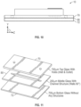
- FIG. 11 is a perspective view of components of an exemplary sample vessel in accordance with the present disclosure.
- FIG. 12 is a graphical representation of total displacement of an exemplary lysis device in accordance with the present disclosure.
- FIG. 13 is a plan view of pressure distribution in a microchannel of an exemplary sample vessel in accordance with the present disclosure.
- FIG. 14 is a plan view of fluid velocity in a microchannel of an exemplary sample vessel in accordance with the present disclosure.
- FIG. 15 is a perspective view of an exemplary analyzer in accordance with the present disclosure.
- FIG. 16 is a perspective view of components of an exemplary analyzer in accordance with the present disclosure.
- FIG. 17 is a perspective view of components of an exemplary analyzer in accordance with the present disclosure.
- FIG. 18 is a schematic view of components of an exemplary analyzer in accordance with the present disclosure.
- FIG. 19 is a schematic of determination of an absorption spectrum in accordance with the present disclosure.
- FIG. 20 illustrates spectral profile coefficients of the hemoglobin forms.
- FIG. 21 illustrates a frequency sweep of a first signal generated by a piezo element and a resulting second signal from vibration of a first sample vessel and a resulting second signal from vibration of a second sample vessel.
- FIG. 23 illustrates a flow chart of an exemplary method of calibrating a piezo element to provide sound waves in accordance with the present disclosure.
- the mechanisms proposed in this disclosure circumvent the problems described above.
- the present disclosure describes lysis devices, analyzers, and lysis methods, including a lysis device configured to lyse red blood cells in a sample vessel by means of ultrasonic acoustic waves, shear forces, pressure, and/or fluid movement, generated in the sample vessel by at least one piezo element connected to the sample vessel and driven at one or more particular excitation frequency, or range of excitation frequencies.
- the at least one piezo element is a single piezo electric transducer configured to generate acoustic waves and configured to measure vibration signals as described herein.
- the at least one piezo element may be a first piezo electric transducer configured to generate acoustic waves and a second piezo electric sensor configured to measure vibration signals from the sample vessel.
- the at least one piezo element may be a first piezo electric transducer configured to generate acoustic waves and a sensor is provided to measure the resulting vibration signal.
- the sensor configured to measure vibration signals is external and separate from the lysis device.
- the present disclosure further describes an analyzer configured to receive and interact with the lysis device for calibrating the piezo element and/or testing a sample in the sample vessel, as well as methods of use.
- the term “substantially” means that the subsequently described parameter, event, or circumstance completely occurs or that the subsequently described parameter, event, or circumstance occurs to a great extent or degree.
- the term “substantially” means that the subsequently described parameter, event, or circumstance occurs at least 90% of the time, or at least 91%, or at least 92%, or at least 93%, or at least 94%, or at least 95%, or at least 96%, or at least 97%, or at least 98%, or at least 99%, of the time, or means that the dimension or measurement is within at least 90%, or at least 91%, or at least 92%, or at least 93%, or at least 94%, or at least 95%, or at least 96%, or at least 97%, or at least 98%, or at least 99%, of the referenced dimension or measurement.
- any reference to “one embodiment” or “an embodiment” means that a particular element, feature, structure, or characteristic described in connection with the embodiment is included in at least one embodiment.
- the appearances of the phrase “in one embodiment” in various places in the specification are not necessarily all referring to the same embodiment.
- the lysis device 10 is an acoustophoretic lysis device having a sample vessel 12 and at least one piezo element 14 attached (e.g., bonded, spring loaded, matingly engaged) to the sample vessel 12 .
- the lysis device 10 may be a monolithic structure, such as that formed by the sample vessel 12 and the at least one piezo element 14 bonded together using a suitable bonding material, such as epoxy, for example.
- the length L M of the microchannel 22 may be based at least in part on a predetermined number of acoustic nodes to be created in the microchannel 22 .
- the length L M microchannel 22 may be based on the width w M of approximately two millimeters and wherein whole blood wave propagation speed is approximately 1500 m/s, a calculated single acoustic node is at 350 kHz.
- the at least one piezo element 14 may be configured and/or positioned in relation to the microchannel 22 such that it does not block light from moving through the microchannel 22 from the top or the bottom of the sample vessel 12 .
- at least a portion of the at least one piezo element 14 may be offset from the microchannel 22 such that the at least one piezo element 14 or a portion of the at least one piezo element 14 is configured to allow light to enter the microchannel 22 from outside of the sample vessel 12 .
- the at least one piezo element 14 has a length L P and has a longitudinal axis along the length L P that is orientated substantially parallel to the longitudinal axis of the sample vessel 12 .
- the at least one piezo element 14 in serving as an acoustic transducer may be configured to produce ultrasonic sound waves having a resonant frequency that resonates in the blood sample 52 in the microchannel 22 of the sample vessel 12 such that walls of red blood cells in the blood sample 52 are ruptured.
- the at least one piezo element 14 in serving as an acoustic transducer may be configured to produce ultrasonic sound waves (which may also be referred to herein as ultrasonic acoustic waves) having a frequency that causes cavitation in the blood sample 52 , thereby rupturing the walls of the red blood cells.
- the at least one piezo element 14 has a first resonant frequency and the monolithic structure of the lysis device 10 has a second resonant frequency spaced spectrally from the first resonant frequency, the second resonant frequency being a frequency of sound waves that is generated by the at least one piezo element 14 and introduced into the sample vessel 12 thereby causing cavitation in the blood sample 52 , thereby rupturing the walls of the red blood cells.
- the at least one piezo element 14 may be configured to generate sound waves, and additionally, measure the resulting sound wave produced by the sample vessel 12 .
- the at least one piezo element 14 may be a plurality of piezo elements with at least one piezo element configured to generate the acoustic sound wave and at least one piezo element configured to measure the resulting sound wave produced by the sample vessel 12 .
- the lysis device 10 may include the sample vessel 12 bonded to at least a portion of the at least one piezo element 14 .
- the sample vessel 12 may be formed of glass and/or the like.
- the microchannel 22 may have width w M of approximately two millimeters with an aspect ratio of 0.05 to 0.125.
- the sample vessel 12 may have a width w SV of approximately twelve millimeters with an aspect ratio of 1.4 to 1.9.
- the at least one piezo element 14 may be configured to produce ultrasonic sound waves in the range of 330 kHz to 350 kHz with peak pressure within the microchannel 22 of five MPa (as shown in FIG. 13 ), and peak velocity up to eight m/s (as shown in FIG. 14 ).
- FIGS. 13 and 14 illustrate an exemplary pressure distribution ( FIG. 13 ) and exemplary fluid velocity ( FIG. 14 ) of the blood sample 52 in the microchannel 22 when the at least one piezo element 14 is activated.
- f the frequency
- ⁇ the wave speed in fluid
- ⁇ the wavelength (e.g., wavelength ⁇ is 1 ⁇ 2 of the width of the microchannel 22 ).
- Ultrasonic sound waves inside the microchannel 22 and/or the at least one piezo element 14 may produce undesired heat in the system and/or undesired heat in the blood sample 52 in the microchannel 22 .
- the at least one piezo element 14 may be operated to produce ultrasonic sound waves at a particular frequency for a predetermined period of time t.
- the at least one piezo element 14 may be operated to generate sound waves having the second resonant frequency for between approximately one second and approximately two seconds.
- the at least one piezo element 14 may be operated to generate sound waves having the second resonant frequency for less than approximately one and a half seconds.
- the lysis device 10 may be configured to operate the at least one piezo element 14 as an acoustic transducer for equal to or less than 1.5 seconds to result in 99.99% red blood cell lysis. In one example, the lysis device 10 may be configured to operate the at least one piezo element 14 as an acoustic transducer for approximately ten seconds or less.
- the ultrasonic sound waves inside the microchannel 22 disrupt the blood cells and cell walls into fine particles which produce less light scattering during optical measurement of the blood sample 52 than larger particles.
- the at least one piezo element 14 performing as an acoustic transducer may be configured to produce ultrasonic sound waves in a range of frequencies and the second resonant frequency may be within the range of frequencies.
- the at least one piezo element 14 may be configured to produce ultrasonic sound waves in a range of frequencies that is greater than approximately 300 kHz. In some embodiments, the at least one piezo element 14 may be configured to measure sound waves in a range of frequencies that is greater than approximately 300 kHz.
- the at least one piezo element 14 may be configured to produce ultrasonic sound waves in the range of approximately 330 kHz to approximately 350 kHz. In some embodiments, the at least one piezo element 14 may also be configured to measure ultrasonic sounds waves in the range of approximately 330 kHz to approximately 350 kHz.
- resonant frequency for the sample vessel 12 and/or blood sample 52 may be determined to calibrate the sound waves generated by the at least one piezo element 14 .
- the at least one piezo element 14 may generate a first signal 300 of ultrasonic acoustic standing waves at a first frequency sweep 302 driven from frequency f 1 to frequency f n for a first duration of time t to the sample vessel 12 .
- the first frequency sweep 302 is a frequency sweep range that may cover configuration tolerances.
- the first frequency sweep 302 may be in a range of approximately 40-50 kHz about the known resonance of glass, e.g., 300-350 kHz.
- the at least one piezo element 14 may then cease to provide the first signal 300 and then subsequently receive a second signal 304 comprising a vibration signal (e.g., from the sample vessel 12 ) due to the first signal 300 .
- the at least one piezo element 14 may be a single device configured to both generate the first signal 300 and measure the second signal 302 comprising a vibration signal as illustrated in FIG. 1 A and FIG. 21 .
- the at least one piezo element 14 may be two or more separate devices with at least the first piezo element 14 a configured to generate the first signal 300 and at least the second piezo element 14 b configured to measure the second signal 304 (e.g., having the vibration signal from the sample vessel 12 ) as illustrated in FIGS. 1 A and 21 .
- the first signal 300 and the second signal 304 having the vibration signal may be compared to determine resonant frequency of the sample vessel 12 , blood sample 52 , surrounding environment, lysis device 10 and/or combinations thereof.
- the first signal 300 is provided to the sample vessel 12 and the response second signal 304 is shown below the first signal 300 .
- the second signal 304 illustrates a higher amplitude at a relative maximum 306 .
- the relative maximum 306 indicates the resonant frequency of the lysis device 10 , for example.
- the optimum frequency for the sound waves generated by the at least one piezo element 14 may include, or exclude the resonant frequency.
- the determined resonant frequency may be analyzed and used to provide optimum results for rupturing blood cells in the blood sample 52 in the shortest time with the least temperature increase. To that end, the determined resonant frequency may be used to calibrate the signal to be emitted by the at least one piezo element 14 in order to lyse blood cells within the blood sample 52 . The at least one piezo element 14 may then emit a calibrated signal using the determined resonant frequency with an intensity and duration to lyse blood cells within the blood sample 52 within the microchannel 22 of the sample vessel 12 .
- the response second signal 304 a may have an amplitude at a relative maximum 308 indicating the optimal resonant frequency for use in the system.
- each sample vessel 12 and/or lysis device 10 may be calibrated based on the determined resonant frequency for use in the lysis device 10 and/or sample vessel 12 .
- each lysis device 10 may be calibrated throughout the life cycle of the lysis device 10 .
- the at least one piezo element 14 may then emit a calibrated signal using the determined resonant frequency with an intensity and duration to lyse blood cells within the blood sample 52 within the microchannel 22 of the sample vessel 12 .
- FIG. 22 illustrates another exemplary method for determining resonant frequency for calibrating the signal to be used by the at least one piezo element 14 .
- the at least one piezo element 14 may be driven to emit the first signal 300 .
- the first signal 300 includes a series of frequencies, F 1 -F n with an observation period between the emission of each adjacent pair of frequencies. During the observation period(s) the at least one piezo element 14 is not driven, and is maintained at a high Z value.
- the piezo element 14 produces a second signal 304 indicative of the vibration from the sample vessel 12 .
- the second signal has a decay envelope 310 during each observation period that may be analyzed to determine a resonant frequency of the sample vessel 12 .
- the at least one piezo element 14 may be configured to provide the first frequency sweep 302 in a range in steps (e.g., one kHz of frequency). In some embodiments, the at least one piezo element 14 may provide the first frequency sweep 302 without further calibrating the resonant frequency. To that end, the at least one piezo element 14 may provide the first frequency sweep over a particular frequency range such that an estimated resonant frequency may be obtained for the lysis device 10 plus the blood sample 52 , even in light of variances in the geometry and materials of the lysis device 10 .
- the at least one piezo element 14 may be configured to sweep the frequency range between approximately 330 kHz and approximately 350 kHz in approximately one kHz steps, less than one kHz steps, or greater than one kHz steps.
- the at least one piezo element 14 may be configured to provide the first frequency sweep 302 from approximately 330 kHz to approximately 350 kHz and/or the at least one piezo element 14 may be configured to provide the first frequency sweep 302 from approximately 350 kHz to approximately 330 kHz, for example.
- the at least one piezo element 14 may be configured to provide the first frequency sweep 302 in a frequency range over a duration of time t greater than zero seconds, and less than five seconds, less than four seconds, less than three seconds, less than two seconds, and/or less than one second. In some embodiments, the at least one piezo element 14 may be configured to provide the first frequency sweep 302 for a duration of time t between approximately one second and approximately two seconds.
- the lysis device 10 may lyse the blood cells in the blood sample 52 by inducing shear and bending modes in the microchannel 22 of the sample vessel 12 .
- the at least one piezo element 14 e.g., rigid and/or bonded
- the at least one piezo element 14 may be displaced (e.g., transverse displacement), resulting in vibration and/or movement of the sample vessel 12 .
- the at least one piezo element 14 may change shape, contracting and/or elongating (e.g., transverse displacement) as shown in FIG. 12 . Movement of the at least one piezo element 14 may be translated to the sample vessel 12 .
- FIG. 12 illustrates a graphical representation of exemplary total displacement of the at least one piezo element 14 in an exemplary operation of the at least one piezo element 14 .
- Shear force may be developed at the attachment (e.g., bond) between the at least one piezo element 14 and the sample vessel 12 when the at least one piezo element 14 is activated.
- the shear stress may result in high pressures inside of the microchannel 22 .
- pressure may be approximately 5 MPa.
- pressure may be in a range of approximately 3 MPa to approximately 7 MPA.
- pressure may be controlled by the level of contraction and/or elongation of the at least one piezo element 14 .
- the level of contraction and/or elongation of the at least one piezo element 14 may depend on the electric field strength of the at least one piezo element 14 .
- the combination of acoustic standing waves inside the microchannel 22 along with shear force and/or bending of the sample vessel 12 may cause cavitation in the blood sample 52 in the microchannel 22 .
- Such cavitation may cause the rupture of the cell walls within the blood sample 52 .
- the lysis device 10 may be a component of an analyzer 100 .
- the analyzer 100 may comprise the lysis device 10 , an absorbance spectrophotometer 102 , a fluidic distribution system 104 , and/or a controller 106 .
- the lysis device 10 is removable and/or exchangeable from the other components of the analyzer 100 .
- the lysis device 10 is permanently attached to the analyzer 100 with one or more components of the lysis device 10 being removable and/or exchangeable.
- the analyzer 100 may further comprise a mount 108 configured to receive and/or position the lysis device 10 .
- the lysis device 10 may be held (e.g., clamped) within the mount 108 such that the lysis device 10 is able to vibrate and/or move within a range of vibration and/or movement.
- the controller 106 of the analyzer 100 may further comprise one or more processors 140 and one or more non-transitory computer readable medium 142 .
- the one or more processors 140 and the one or more non-transitory computer readable medium 142 may be part of the controller 106 .
- one or more of the processors 140 and/or the non-transitory computer readable medium 142 may be located external to the controller 106 and/or external to the other components of the analyzer 100 .
- the absorbance spectrophotometer 102 may comprise a transmitter 112 and a receiver 114 positioned adjacent to the sample vessel 12 , the transmitter 112 positioned to emit a medium 116 through the top 40 , the bottom 42 , and the microchannel 22 , and the receiver 114 is positioned to receive at least a portion of the medium 116 after the portion of the medium 116 has passed through the top 40 , the bottom 42 , and the microchannel 22 .
- the transmitter 112 may be a light source and the medium 116 may be light.
- the light source may be, but is not limited to, one or more light emitting diode, one or more tube lights, one or more electric bulbs, sunlight, and/or combinations thereof.
- the light source may be one or more light emitting diodes providing white light having wavelengths in a range from approximately 450-700 nanometers.
- the absorbance spectrophotometer 102 may be configured to measure the intensity of light in a part of the spectrum, especially as transmitted or emitted by particular substances in the blood sample 52 in the microchannel 22 of the sample vessel 12 .
- the absorbance spectrophotometer 102 may be configured to measure how much a chemical substance absorbs light by measuring the intensity of light as a beam of light passes through the blood sample 52 , or other fluidic sample 52 . Each compound in the sample or solution absorbs or transmits light over a particular range of wavelengths.
- the fluidic distribution system 104 may have an inlet 120 fluidly connectable to the first port 24 , and an outlet 122 fluidly connectable to the second port 26 of the sample vessel 12 of the lysis device 10 .
- the fluidic distribution system 104 may move one or more fluidic samples 52 , such as a blank sample or a blood sample or a washing solution, through the inlet 120 through the first port 24 into the microchannel 22 of the sample vessel 12 .
- fluidic samples 52 such as a blank sample or a blood sample or a washing solution
- blood sample 52 is used throughout the description; although one skilled in the art will appreciate other fluidic samples (e.g., liquid and gas) may be used in accordance with the present disclosure.
- the fluidic distribution system 104 may flush the microchannel 22 , expelling material within the microchannel 22 through the second port 26 of the sample vessel 12 and out of the outlet 122 .
- the fluidic distribution system 104 may be operated automatically, manually, or a combination of automatically and manually.
- the controller 106 may be electrically connected to the at least one piezo element 14 of the lysis device 10 .
- the controller 106 may be configured to provide signals to the at least one piezo element 14 , that when received by the at least one piezo element 14 cause the at least one piezo element 14 to emit ultrasonic acoustic waves at one or more frequency and/or range of frequencies.
- FIG. 23 illustrates a flow chart 320 of an exemplary method for calibrating the at least one piezo element 14 to emit ultrasonic acoustic waves.
- the controller 106 may be configured to provide one or more signals to the at least one piezo element 14 to cause the at least one piezo element 14 to emit a first signal 300 having ultrasonic acoustic waves over a first frequency sweep 302 as shown in FIGS. 21 and 23 .
- the controller 106 may adjust the at least one piezo element to cease providing the first signal 300 .
- the controller 106 may receive the second signal 304 from the at least one piezo element with the second signal 304 comprising the vibration signal (e.g., from the sample vessel 12 ) resulting from the first signal 300 causing the sample vessel 12 to vibrate.
- the sample vessel 12 may include the blood sample 52 or be void of the blood sample 52 .
- the controller 106 may compare the first signal 300 with the second signal 304 (e.g., amplitude, decay envelope) and identify within the second signal 304 the resonant frequency.
- the controller 106 may be configured to provide one or more signals to the at least one piezo element 14 to cause the at least one piezo element 14 to emit ultrasonic acoustic waves based on the determined resonant frequency such that the ultrasonic acoustic waves have an intensity and duration to lyse blood cells within the blood sample 52 .
- the mount 108 may hold the lysis device 10 in place between the transmitter 112 and the receiver 114 and may position the lysis device 10 to be operably connected to the fluidic distribution system 104 and the controller 106 (see FIG. 17 ).
- the mount 108 may be configured to stabilize the lysis device 10 in position without applying a force that would significantly change the acoustic impedance of the monolithic structure of the lysis device 10 .
- the mount 108 may include one or more clamps that apply a clamping force at or below approximately twenty newtons (N).
- an absorption spectrum may be calculated based on known calculations for absorption for liquid mediums.
- determining one or more oximetry parameters may further comprise analyzing spectral profile coefficients of hemoglobin forms, such as one or more of the following: carboxyhemoglobin (COHB), oxyhemoglobin (O2HB), methemoglobin (METHB), deoxyhemoglobin (HHB), neonatal Bilirubin (NBILI), Cyan Methemoglobin (CN_MET_B), Sulfhemoglobin (SULF_HIGH), and Methylene blue dye (METH_BLUE_A).
- COHB carboxyhemoglobin
- O2HB oxyhemoglobin
- METHB methemoglobin
- HHB deoxyhemoglobin
- NBILI neonatal Bilirubin
- Cyan Methemoglobin CN_MET_B
- Sulfhemoglobin SULF_HIGH
- METH_BLUE_A Methylene blue dye
- the analyzer 100 may measure total hemoglobin (THB) and/or one or more of hemoglobin fractions, such as the following: oxyhemoglobin (O2HB), methemoglobin (METHB), deoxyhemoglobin (HHB), carboxyhemoglobin (COHB).
- TLB total hemoglobin
- O2HB oxyhemoglobin
- METHB methemoglobin
- HHB deoxyhemoglobin
- COHB carboxyhemoglobin
Landscapes
- Chemical & Material Sciences (AREA)
- Health & Medical Sciences (AREA)
- General Health & Medical Sciences (AREA)
- Analytical Chemistry (AREA)
- Physics & Mathematics (AREA)
- Life Sciences & Earth Sciences (AREA)
- Biochemistry (AREA)
- General Physics & Mathematics (AREA)
- Immunology (AREA)
- Pathology (AREA)
- Chemical Kinetics & Catalysis (AREA)
- Clinical Laboratory Science (AREA)
- Dispersion Chemistry (AREA)
- Hematology (AREA)
- Acoustics & Sound (AREA)
- Investigating Or Analysing Biological Materials (AREA)
- Investigating Or Analyzing Materials By The Use Of Ultrasonic Waves (AREA)
- Sampling And Sample Adjustment (AREA)
- Transducers For Ultrasonic Waves (AREA)
- Measurement Of Levels Of Liquids Or Fluent Solid Materials (AREA)
- Investigating Or Analysing Materials By Optical Means (AREA)
- Automatic Analysis And Handling Materials Therefor (AREA)
- Apparatus Associated With Microorganisms And Enzymes (AREA)
Abstract
Description
wherein f is the frequency, ν the wave speed in fluid and λ the wavelength (e.g., wavelength λ is ½ of the width of the microchannel 22).
Claims (19)
Priority Applications (1)
| Application Number | Priority Date | Filing Date | Title |
|---|---|---|---|
| US18/007,058 US12031890B2 (en) | 2020-08-03 | 2021-07-23 | Lysis devices having a piezo element and methods |
Applications Claiming Priority (3)
| Application Number | Priority Date | Filing Date | Title |
|---|---|---|---|
| US202063060301P | 2020-08-03 | 2020-08-03 | |
| PCT/US2021/042953 WO2022031459A1 (en) | 2020-08-03 | 2021-07-23 | Lysis devices having a piezo element and methods |
| US18/007,058 US12031890B2 (en) | 2020-08-03 | 2021-07-23 | Lysis devices having a piezo element and methods |
Related Parent Applications (1)
| Application Number | Title | Priority Date | Filing Date |
|---|---|---|---|
| PCT/US2021/042953 A-371-Of-International WO2022031459A1 (en) | 2020-08-03 | 2021-07-23 | Lysis devices having a piezo element and methods |
Related Child Applications (1)
| Application Number | Title | Priority Date | Filing Date |
|---|---|---|---|
| US18/738,633 Continuation US12553803B2 (en) | 2020-08-03 | 2024-06-10 | Lysis devices having a piezo element and methods |
Publications (2)
| Publication Number | Publication Date |
|---|---|
| US20230213414A1 US20230213414A1 (en) | 2023-07-06 |
| US12031890B2 true US12031890B2 (en) | 2024-07-09 |
Family
ID=80118461
Family Applications (2)
| Application Number | Title | Priority Date | Filing Date |
|---|---|---|---|
| US18/007,058 Active US12031890B2 (en) | 2020-08-03 | 2021-07-23 | Lysis devices having a piezo element and methods |
| US18/738,633 Active US12553803B2 (en) | 2020-08-03 | 2024-06-10 | Lysis devices having a piezo element and methods |
Family Applications After (1)
| Application Number | Title | Priority Date | Filing Date |
|---|---|---|---|
| US18/738,633 Active US12553803B2 (en) | 2020-08-03 | 2024-06-10 | Lysis devices having a piezo element and methods |
Country Status (7)
| Country | Link |
|---|---|
| US (2) | US12031890B2 (en) |
| EP (1) | EP4188604A4 (en) |
| JP (1) | JP7442014B2 (en) |
| CA (1) | CA3187872A1 (en) |
| IL (1) | IL300159B1 (en) |
| MX (1) | MX2023001347A (en) |
| WO (1) | WO2022031459A1 (en) |
Families Citing this family (6)
| Publication number | Priority date | Publication date | Assignee | Title |
|---|---|---|---|---|
| US12478291B2 (en) | 2019-01-29 | 2025-11-25 | Instrumentation Laboratory Company | Hematocrit level detection using IR laser refraction |
| WO2021222084A1 (en) * | 2020-04-28 | 2021-11-04 | Siemens Healthcare Diagnostics Inc. | Acoustophoretic lysis devices and methods |
| USD1014780S1 (en) | 2022-04-15 | 2024-02-13 | Instrumentation Laboratory Co. | Cuvette |
| US12280375B2 (en) | 2022-06-17 | 2025-04-22 | Siemens Healthcare Diagnostics Inc. | Acoustophoresis devices having conductive electrodes and methods |
| CN119451746A (en) * | 2022-06-30 | 2025-02-14 | 美国西门子医学诊断股份有限公司 | Acoustophoresis analysis device and method |
| US12584902B2 (en) | 2023-12-10 | 2026-03-24 | Instrumentation Laboratory Company | Acoustic separation of a test sample |
Citations (21)
| Publication number | Priority date | Publication date | Assignee | Title |
|---|---|---|---|---|
| JPS60192249A (en) | 1984-03-12 | 1985-09-30 | Matsushita Electric Works Ltd | Method for measuring blood sugar value |
| US5375595A (en) | 1993-03-17 | 1994-12-27 | The Regents Of The University Of Calif. | Apparatus and method for non-contact, acoustic resonance determination of intraocular pressure |
| JPH11326155A (en) | 1998-05-20 | 1999-11-26 | Hitachi Ltd | Cell sorting device |
| US6690958B1 (en) * | 2002-05-07 | 2004-02-10 | Nostix Llc | Ultrasound-guided near infrared spectrophotometer |
| JP2006506607A (en) | 2002-08-28 | 2006-02-23 | セパレーション テクノロジー,インコーポレーティッド | Method and apparatus for ultrasonic measurement of red blood cell index |
| US20090099485A1 (en) * | 2007-10-16 | 2009-04-16 | Sarvazyan Armen P | Ultrasound standing wave method and apparatus for tissue treatment |
| WO2009144209A1 (en) | 2008-05-27 | 2009-12-03 | Alifax Holding Spa | Mixing device and relative mixing method |
| US20100015691A1 (en) | 2008-07-16 | 2010-01-21 | Radiometer Medical Aps | Apparatus for Hemolyzing a Blood Sample and for Measuring at Least One Parameter Thereof |
| JP2011503562A (en) | 2007-11-13 | 2011-01-27 | エフ.ホフマン−ラ ロシュ アーゲー | How to use cuvettes and cuvettes |
| US20130012927A1 (en) * | 2009-12-04 | 2013-01-10 | Sound Surgical Technologies Llc | Selective lysing of cells using ultrasound |
| JP2015503760A (en) | 2012-01-16 | 2015-02-02 | コーニンクレッカ フィリップス エヌ ヴェ | Determining the presence of target molecules in body fluids containing cells |
| US20150177111A1 (en) | 2013-12-23 | 2015-06-25 | Becton, Dickinson And Company | Devices and methods for processing a biological sample |
| US9096823B1 (en) * | 2010-08-31 | 2015-08-04 | Sandia Corporation | Microfluidic device for acoustic cell lysis |
| US20160097696A1 (en) | 2014-10-01 | 2016-04-07 | Mueller International, Llc | Piezoelectric vibration sensor for fluid leak detection |
| US20170122911A1 (en) | 2015-10-30 | 2017-05-04 | Qorvo Us, Inc. | Multi-frequency baw mixing and sensing system and method |
| US20180003624A1 (en) | 2014-12-17 | 2018-01-04 | Siemens Aktiengesellschaft | Absorption Spectrometer |
| JP2019062890A (en) | 2017-10-02 | 2019-04-25 | アークレイ株式会社 | Measurement of glycated protein |
| US20190121460A1 (en) * | 2017-10-24 | 2019-04-25 | Interface Optoelectronic (Chengdu) Co., Ltd | Acoustic touch device and touch judging method |
| JP2020502539A (en) | 2016-10-07 | 2020-01-23 | アコーソート アーベーAcousort Ab | Methods and systems for optical or electrical measurements in dispersive fluids |
| WO2021222084A1 (en) | 2020-04-28 | 2021-11-04 | Siemens Healthcare Diagnostics Inc. | Acoustophoretic lysis devices and methods |
| EP4090465A2 (en) | 2020-01-13 | 2022-11-23 | Lumiradx Uk Ltd | Fluid control in microfluidic devices |
Family Cites Families (4)
| Publication number | Priority date | Publication date | Assignee | Title |
|---|---|---|---|---|
| US6014652A (en) * | 1994-11-02 | 2000-01-11 | Foster-Miller, Inc. | Object classification and identification system |
| US7416535B1 (en) * | 1996-12-30 | 2008-08-26 | Daniele Kenny | Neoplastic cell destruction device and method utilizing low frequency sound waves to disrupt or displace cellular materials |
| US11745177B2 (en) | 2019-01-10 | 2023-09-05 | Instrumentation Laboratory Company | Ultrasound lysing of whole blood |
| NL2026048B1 (en) | 2020-07-10 | 2022-03-15 | Lumicks Ca Holding B V | Methods and systems for manipulating a particle |
-
2021
- 2021-07-23 MX MX2023001347A patent/MX2023001347A/en unknown
- 2021-07-23 EP EP21854559.8A patent/EP4188604A4/en active Pending
- 2021-07-23 US US18/007,058 patent/US12031890B2/en active Active
- 2021-07-23 CA CA3187872A patent/CA3187872A1/en active Pending
- 2021-07-23 JP JP2023507392A patent/JP7442014B2/en active Active
- 2021-07-23 WO PCT/US2021/042953 patent/WO2022031459A1/en not_active Ceased
-
2023
- 2023-01-24 IL IL300159A patent/IL300159B1/en unknown
-
2024
- 2024-06-10 US US18/738,633 patent/US12553803B2/en active Active
Patent Citations (22)
| Publication number | Priority date | Publication date | Assignee | Title |
|---|---|---|---|---|
| JPS60192249A (en) | 1984-03-12 | 1985-09-30 | Matsushita Electric Works Ltd | Method for measuring blood sugar value |
| US5375595A (en) | 1993-03-17 | 1994-12-27 | The Regents Of The University Of Calif. | Apparatus and method for non-contact, acoustic resonance determination of intraocular pressure |
| JPH11326155A (en) | 1998-05-20 | 1999-11-26 | Hitachi Ltd | Cell sorting device |
| US6690958B1 (en) * | 2002-05-07 | 2004-02-10 | Nostix Llc | Ultrasound-guided near infrared spectrophotometer |
| JP2006506607A (en) | 2002-08-28 | 2006-02-23 | セパレーション テクノロジー,インコーポレーティッド | Method and apparatus for ultrasonic measurement of red blood cell index |
| US20090099485A1 (en) * | 2007-10-16 | 2009-04-16 | Sarvazyan Armen P | Ultrasound standing wave method and apparatus for tissue treatment |
| JP2011503562A (en) | 2007-11-13 | 2011-01-27 | エフ.ホフマン−ラ ロシュ アーゲー | How to use cuvettes and cuvettes |
| WO2009144209A1 (en) | 2008-05-27 | 2009-12-03 | Alifax Holding Spa | Mixing device and relative mixing method |
| US20100015691A1 (en) | 2008-07-16 | 2010-01-21 | Radiometer Medical Aps | Apparatus for Hemolyzing a Blood Sample and for Measuring at Least One Parameter Thereof |
| US9097701B2 (en) | 2008-07-16 | 2015-08-04 | Radiometer Medical Aps | Apparatus for hemolyzing a blood sample and for measuring at least one parameter thereof |
| US20130012927A1 (en) * | 2009-12-04 | 2013-01-10 | Sound Surgical Technologies Llc | Selective lysing of cells using ultrasound |
| US9096823B1 (en) * | 2010-08-31 | 2015-08-04 | Sandia Corporation | Microfluidic device for acoustic cell lysis |
| JP2015503760A (en) | 2012-01-16 | 2015-02-02 | コーニンクレッカ フィリップス エヌ ヴェ | Determining the presence of target molecules in body fluids containing cells |
| US20150177111A1 (en) | 2013-12-23 | 2015-06-25 | Becton, Dickinson And Company | Devices and methods for processing a biological sample |
| US20160097696A1 (en) | 2014-10-01 | 2016-04-07 | Mueller International, Llc | Piezoelectric vibration sensor for fluid leak detection |
| US20180003624A1 (en) | 2014-12-17 | 2018-01-04 | Siemens Aktiengesellschaft | Absorption Spectrometer |
| US20170122911A1 (en) | 2015-10-30 | 2017-05-04 | Qorvo Us, Inc. | Multi-frequency baw mixing and sensing system and method |
| JP2020502539A (en) | 2016-10-07 | 2020-01-23 | アコーソート アーベーAcousort Ab | Methods and systems for optical or electrical measurements in dispersive fluids |
| JP2019062890A (en) | 2017-10-02 | 2019-04-25 | アークレイ株式会社 | Measurement of glycated protein |
| US20190121460A1 (en) * | 2017-10-24 | 2019-04-25 | Interface Optoelectronic (Chengdu) Co., Ltd | Acoustic touch device and touch judging method |
| EP4090465A2 (en) | 2020-01-13 | 2022-11-23 | Lumiradx Uk Ltd | Fluid control in microfluidic devices |
| WO2021222084A1 (en) | 2020-04-28 | 2021-11-04 | Siemens Healthcare Diagnostics Inc. | Acoustophoretic lysis devices and methods |
Non-Patent Citations (1)
| Title |
|---|
| International Search Report and Written Opinion of International Application No. PCT/US2021/042953 dated Dec. 30, 2021. |
Also Published As
| Publication number | Publication date |
|---|---|
| US12553803B2 (en) | 2026-02-17 |
| MX2023001347A (en) | 2023-02-27 |
| JP2023536735A (en) | 2023-08-29 |
| CA3187872A1 (en) | 2022-02-10 |
| IL300159B1 (en) | 2026-03-01 |
| IL300159A (en) | 2023-03-01 |
| JP7442014B2 (en) | 2024-03-01 |
| EP4188604A4 (en) | 2024-01-31 |
| US20240361211A1 (en) | 2024-10-31 |
| EP4188604A1 (en) | 2023-06-07 |
| US20230213414A1 (en) | 2023-07-06 |
| WO2022031459A1 (en) | 2022-02-10 |
Similar Documents
| Publication | Publication Date | Title |
|---|---|---|
| US12553803B2 (en) | Lysis devices having a piezo element and methods | |
| US11426727B2 (en) | Acoustophoretic lysis devices and methods | |
| US20250319466A1 (en) | Acoustophoretic analyzation devices and methods | |
| EP2321643B1 (en) | Apparatus for hemolyzing a blood sample and for measuring at least one parameter thereof | |
| WO2010009543A1 (en) | A microfluidic device and method for fabricating the microfluidic device | |
| EP3948254B1 (en) | Methods and apparatus for performing sample measurements using visible light on samples manipulated with acoustic waves | |
| JP2007501403A (en) | Optical fiber array biochip based on spectral change rule of white light reflection interference | |
| US20250205705A1 (en) | Acoustophoresis devices having conductive electrodes and methods | |
| CN114112923A (en) | Photoacoustic microfluidic detection system and detection method | |
| WO2020146583A1 (en) | Ultrasound lysing of whole blood | |
| CA3259662C (en) | Acoustophoresis devices having conductive electrodes and methods | |
| HK40080177A (en) | Acoustophoretic lysis devices and methods | |
| JP2020526773A (en) | Methods and devices for interfacing sensors with fluid materials | |
| CN216926576U (en) | Photoacoustic microfluidic detection system | |
| CHEN | Jiaming GAO | |
| Chandrasekaran et al. | Integrated micro-total analysis system (uTAS) for biophotonic enzymatic detections | |
| Lapsley | Integrating optical techniques such as reflection, interferometry, scattering and fluorescence; bulk and surface acoustic waves; and microfluidics for measuring refractive index, viscosity, diffusion, surface tension, cell properties, and for sorting cells | |
| HK1144963B (en) | Haemolysator | |
| HK1144963A1 (en) | Haemolysator |
Legal Events
| Date | Code | Title | Description |
|---|---|---|---|
| AS | Assignment |
Owner name: SIEMENS HEALTHCARE DIAGNOSTICS INC., NEW YORK Free format text: ASSIGNMENT OF ASSIGNORS INTEREST;ASSIGNOR:SIEMENS HEALTHCARE GMBH;REEL/FRAME:062506/0013 Effective date: 20210914 Owner name: SIEMENS HEALTHCARE GMBH, GERMANY Free format text: ASSIGNMENT OF ASSIGNORS INTEREST;ASSIGNOR:PAULICKA, PETER;REEL/FRAME:062505/0953 Effective date: 20210824 Owner name: SIEMENS HEALTHCARE DIAGNOSTICS INC., NEW YORK Free format text: ASSIGNMENT OF ASSIGNORS INTEREST;ASSIGNORS:JASPERSE, JEFFREY R.;BENSON, PAUL;SIGNING DATES FROM 20210824 TO 20210929;REEL/FRAME:062505/0873 |
|
| FEPP | Fee payment procedure |
Free format text: ENTITY STATUS SET TO UNDISCOUNTED (ORIGINAL EVENT CODE: BIG.); ENTITY STATUS OF PATENT OWNER: LARGE ENTITY |
|
| STPP | Information on status: patent application and granting procedure in general |
Free format text: RESPONSE TO NON-FINAL OFFICE ACTION ENTERED AND FORWARDED TO EXAMINER |
|
| STPP | Information on status: patent application and granting procedure in general |
Free format text: FINAL REJECTION MAILED |
|
| STPP | Information on status: patent application and granting procedure in general |
Free format text: ADVISORY ACTION MAILED |
|
| STPP | Information on status: patent application and granting procedure in general |
Free format text: DOCKETED NEW CASE - READY FOR EXAMINATION |
|
| STPP | Information on status: patent application and granting procedure in general |
Free format text: NON FINAL ACTION MAILED |
|
| STPP | Information on status: patent application and granting procedure in general |
Free format text: NOTICE OF ALLOWANCE MAILED -- APPLICATION RECEIVED IN OFFICE OF PUBLICATIONS |
|
| STPP | Information on status: patent application and granting procedure in general |
Free format text: PUBLICATIONS -- ISSUE FEE PAYMENT RECEIVED |
|
| STCF | Information on status: patent grant |
Free format text: PATENTED CASE |