US12031332B2 - Roofing materials and related methods - Google Patents
Roofing materials and related methods Download PDFInfo
- Publication number
- US12031332B2 US12031332B2 US18/489,458 US202318489458A US12031332B2 US 12031332 B2 US12031332 B2 US 12031332B2 US 202318489458 A US202318489458 A US 202318489458A US 12031332 B2 US12031332 B2 US 12031332B2
- Authority
- US
- United States
- Prior art keywords
- layer
- openings
- range
- thickness
- mils
- Prior art date
- Legal status (The legal status is an assumption and is not a legal conclusion. Google has not performed a legal analysis and makes no representation as to the accuracy of the status listed.)
- Active
Links
Images


Classifications
-
- E—FIXED CONSTRUCTIONS
- E04—BUILDING
- E04D—ROOF COVERINGS; SKY-LIGHTS; GUTTERS; ROOF-WORKING TOOLS
- E04D1/00—Roof covering by making use of tiles, slates, shingles, or other small roofing elements
- E04D1/12—Roofing elements shaped as plain tiles or shingles, i.e. with flat outer surface
- E04D1/20—Roofing elements shaped as plain tiles or shingles, i.e. with flat outer surface of plastics; of asphalt; of fibrous materials
-
- B—PERFORMING OPERATIONS; TRANSPORTING
- B32—LAYERED PRODUCTS
- B32B—LAYERED PRODUCTS, i.e. PRODUCTS BUILT-UP OF STRATA OF FLAT OR NON-FLAT, e.g. CELLULAR OR HONEYCOMB, FORM
- B32B27/00—Layered products comprising a layer of synthetic resin
- B32B27/06—Layered products comprising a layer of synthetic resin as the main or only constituent of a layer, which is next to another layer of the same or of a different material
- B32B27/08—Layered products comprising a layer of synthetic resin as the main or only constituent of a layer, which is next to another layer of the same or of a different material of synthetic resin
-
- B—PERFORMING OPERATIONS; TRANSPORTING
- B32—LAYERED PRODUCTS
- B32B—LAYERED PRODUCTS, i.e. PRODUCTS BUILT-UP OF STRATA OF FLAT OR NON-FLAT, e.g. CELLULAR OR HONEYCOMB, FORM
- B32B3/00—Layered products comprising a layer with external or internal discontinuities or unevennesses, or a layer of non-planar shape; Layered products comprising a layer having particular features of form
- B32B3/26—Layered products comprising a layer with external or internal discontinuities or unevennesses, or a layer of non-planar shape; Layered products comprising a layer having particular features of form characterised by a particular shape of the outline of the cross-section of a continuous layer; characterised by a layer with cavities or internal voids ; characterised by an apertured layer
- B32B3/266—Layered products comprising a layer with external or internal discontinuities or unevennesses, or a layer of non-planar shape; Layered products comprising a layer having particular features of form characterised by a particular shape of the outline of the cross-section of a continuous layer; characterised by a layer with cavities or internal voids ; characterised by an apertured layer characterised by an apertured layer, the apertures going through the whole thickness of the layer, e.g. expanded metal, perforated layer, slit layer regular cells B32B3/12
-
- B—PERFORMING OPERATIONS; TRANSPORTING
- B32—LAYERED PRODUCTS
- B32B—LAYERED PRODUCTS, i.e. PRODUCTS BUILT-UP OF STRATA OF FLAT OR NON-FLAT, e.g. CELLULAR OR HONEYCOMB, FORM
- B32B7/00—Layered products characterised by the relation between layers; Layered products characterised by the relative orientation of features between layers, or by the relative values of a measurable parameter between layers, i.e. products comprising layers having different physical, chemical or physicochemical properties; Layered products characterised by the interconnection of layers
- B32B7/04—Interconnection of layers
- B32B7/12—Interconnection of layers using interposed adhesives or interposed materials with bonding properties
-
- B—PERFORMING OPERATIONS; TRANSPORTING
- B32—LAYERED PRODUCTS
- B32B—LAYERED PRODUCTS, i.e. PRODUCTS BUILT-UP OF STRATA OF FLAT OR NON-FLAT, e.g. CELLULAR OR HONEYCOMB, FORM
- B32B2307/00—Properties of the layers or laminate
- B32B2307/40—Properties of the layers or laminate having particular optical properties
- B32B2307/402—Coloured
-
- B—PERFORMING OPERATIONS; TRANSPORTING
- B32—LAYERED PRODUCTS
- B32B—LAYERED PRODUCTS, i.e. PRODUCTS BUILT-UP OF STRATA OF FLAT OR NON-FLAT, e.g. CELLULAR OR HONEYCOMB, FORM
- B32B2419/00—Buildings or parts thereof
- B32B2419/06—Roofs, roof membranes
-
- E—FIXED CONSTRUCTIONS
- E04—BUILDING
- E04D—ROOF COVERINGS; SKY-LIGHTS; GUTTERS; ROOF-WORKING TOOLS
- E04D1/00—Roof covering by making use of tiles, slates, shingles, or other small roofing elements
- E04D1/28—Roofing elements comprising two or more layers, e.g. for insulation
Definitions
- the third layer is attached to the second layer by an adhesive layer.
- the roofing shingle comprises a first layer.
- the first layer comprises a first thermoplastic polymer.
- the roofing shingle comprises a second layer.
- the second layer is located on the first layer.
- the second layer comprises a second thermoplastic polymer.
- a plurality of openings is formed in the second layer.
- each of the plurality of openings extends through the second layer, from a first surface of the second layer to a second surface of the second layer.
- the second surface of the second layer is opposite the first surface of the second layer.
- the second surface of the second layer is an upper surface of the second layer. In some embodiments, at least a portion of an upper surface of the first layer is exposed through the plurality of openings of the second layer.
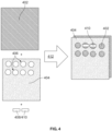
- FIG. 2 is a schematic diagram of a roofing material, according to some embodiments.
- the first layer comprises at least one polymer.
- the at least one polymer comprises at least one thermoplastic polymer.
- the at least one polymer comprises at least one thermoplastic polyolefin (TPO).
- TPO thermoplastic polyolefin
- the at least one polymer comprises at least one of polyethylene, polypropylene, any copolymer thereof, any homopolymer thereof, any polymer blend thereof, or any combination thereof.
- the first layer comprises 20% to 90% by weight of the at least one polymer based on the total weight of the first layer. In some embodiments, the first layer comprises 20% to 80% by weight of the at least one polymer based on the total weight of the first layer. In some embodiments, the first layer comprises 20% to 70% by weight of the at least one polymer based on the total weight of the first layer. In some embodiments, the first layer comprises 30% to 90% by weight of the at least one polymer based on the total weight of the first layer. In some embodiments, the first layer comprises 30% to 80% by weight of the at least one polymer based on the total weight of the first layer.
- the first layer comprises 30% to 70% by weight of the at least one polymer based on the total weight of the first layer. In some embodiments, the first layer comprises 40% to 90% by weight of the at least one polymer based on the total weight of the first layer. In some embodiments, the first layer comprises 40% to 80% by weight of the at least one polymer based on the total weight of the first layer. In some embodiments, the first layer comprises 40% to 70% by weight of the at least one polymer based on the total weight of the first layer. In some embodiments, the first layer comprises 40% to 60% by weight of the at least one polymer based on the total weight of the first layer.
- the first layer comprises 20% to 80% by weight of the at least one polymer based on the total weight of the first layer. In some embodiments, the first layer comprises 30% to 80% by weight of the at least one polymer based on the total weight of the first layer. In some embodiments, the first layer comprises 40% to 80% by weight of the at least one polymer based on the total weight of the first layer. In some embodiments, the first layer comprises 50% to 80% by weight of the at least one polymer based on the total weight of the first layer.
- the at least one additive comprises at least one of group stabilizers, antioxidants, nucleating agents, colorants, pigments, dyes, coloring agents, mold release agents, dispersing agents, UV light absorbers, UV stabilizers, fire retardants, mold release agents, anti-static agents, or any combination thereof.
- the first layer does not comprise the at least one additive. In some embodiments, the first layer does not comprise at least one of the at least one additives.
- the first layer comprises 10% to 60% by weight of the at least one additive based on the total weight of the first layer. In some embodiments, the first layer comprises 10% to 55% by weight of the at least one additive based on the total weight of the first layer. In some embodiments, the first layer comprises 10% to 50% by weight of the at least one additive based on the total weight of the first layer. In some embodiments, the first layer comprises 10% to 45% by weight of the at least one additive based on the total weight of the first layer. In some embodiments, the first layer comprises 10% to 40% by weight of the at least one additive based on the total weight of the first layer. In some embodiments, the first layer comprises 10% to 35% by weight of the at least one additive based on the total weight of the first layer.
- the first layer comprises 10% to 30% by weight of the at least one additive based on the total weight of the first layer. In some embodiments, the first layer comprises 10% to 25% by weight of the at least one additive based on the total weight of the first layer. In some embodiments, the first layer comprises 10% to 20% by weight of the at least one additive based on the total weight of the first layer. In some embodiments, the first layer comprises 10% to 15% by weight of the at least one additive based on the total weight of the first layer.
- the first layer comprises 45% to 90% by weight of the at least one additive based on the total weight of the first layer. In some embodiments, the first layer comprises 50% to 90% by weight of the at least one additive based on the total weight of the first layer. In some embodiments, the first layer comprises 55% to 90% by weight of the at least one additive based on the total weight of the first layer. In some embodiments, the first layer comprises 60% to 90% by weight of the at least one additive based on the total weight of the first layer. In some embodiments, the first layer comprises 65% to 90% by weight of the at least one additive based on the total weight of the first layer. In some embodiments, the first layer comprises 70% to 90% by weight of the at least one additive based on the total weight of the first layer.
- the first layer comprises 20% to 90% by weight of the at least one additive based on the total weight of the first layer. In some embodiments, the first layer comprises 20% to 80% by weight of the at least one additive based on the total weight of the first layer. In some embodiments, the first layer comprises 20% to 70% by weight of the at least one additive based on the total weight of the first layer. In some embodiments, the first layer comprises 30% to 90% by weight of the at least one additive based on the total weight of the first layer. In some embodiments, the first layer comprises 30% to 80% by weight of the at least one additive based on the total weight of the first layer. In some embodiments, the first layer comprises 30% to 70% by weight of the at least one additive based on the total weight of the first layer.
- the first layer comprises 40% to 80% by weight of the at least one additive based on the total weight of the first layer. In some embodiments, the first layer comprises 50% to 80% by weight of the at least one additive based on the total weight of the first layer.
- the first layer has a thickness of 10 mils to 50 mils. In some embodiments, the first layer has a thickness of 10 mils to 48 mils. In some embodiments, the first layer has a thickness of 10 mils to 46 mils. In some embodiments, the first layer has a thickness of 10 mils to 45 mils. In some embodiments, the first layer has a thickness of 10 mils to mils. In some embodiments, the first layer has a thickness of 10 mils to 44 mils. In some embodiments, the first layer has a thickness of 10 mils to 42 mils. In some embodiments, the first layer has a thickness of 10 mils to 40 mils. In some embodiments, the first layer has a thickness of 10 mils to 38 mils.
- the first layer has a thickness of 10 mils to 22 mils. In some embodiments, the first layer has a thickness of 10 mils to 20 mils. In some embodiments, the first layer has a thickness of 10 mils to 18 mils. In some embodiments, the first layer has a thickness of 10 mils to 16 mils. In some embodiments, the first layer has a thickness of 10 mils to 15 mils. In some embodiments, the first layer has a thickness of 10 mils to 14 mils. In some embodiments, the first layer has a thickness of 10 mils to 12 mils.
- the first layer has a thickness of 12 mils to 50 mils. In some embodiments, the first layer has a thickness of 14 mils to 50 mils. In some embodiments, the first layer has a thickness of 15 mils to 50 mils. In some embodiments, the first layer has a thickness of 16 mils to 50 mils. In some embodiments, the first layer has a thickness of 18 mils to 50 mils. In some embodiments, the first layer has a thickness of 20 mils to 50 mils. In some embodiments, the first layer has a thickness of 22 mils to 50 mils. In some embodiments, the first layer has a thickness of 24 mils to 50 mils. In some embodiments, the first layer has a thickness of 25 mils to 50 mils.
- the first layer has a thickness of 26 mils to 50 mils. In some embodiments, the first layer has a thickness of 28 mils to 50 mils. In some embodiments, the first layer has a thickness of 30 mils to 50 mils. In some embodiments, the first layer has a thickness of 32 mils to 50 mils. In some embodiments, the first layer has a thickness of 34 mils to 50 mils. In some embodiments, the first layer has a thickness of 35 mils to 50 mils. In some embodiments, the first layer has a thickness of 36 mils to 50 mils. In some embodiments, the first layer has a thickness of 38 mils to 50 mils. In some embodiments, the first layer has a thickness of 40 mils to 50 mils.
- the first layer has a thickness of 42 mils to 50 mils. In some embodiments, the first layer has a thickness of 44 mils to 50 mils. In some embodiments, the first layer has a thickness of 45 mils to 50 mils. In some embodiments, the first layer has a thickness of 46 mils to 50 mils. In some embodiments, the first layer has a thickness of 48 mils to 50 mils. In some embodiments, the first layer has a thickness of 20 mils to 40 mils. In some embodiments, the first layer has a thickness of 20 mils to 30 mils. In some embodiments, the first layer has a thickness of 30 mils to 40 mils. In some embodiments, the first layer has a thickness of 15 mils to 40 mils. In some embodiments, the first layer has a thickness of 15 mils to 30 mils.
- the first layer has a first color. In some embodiments, the first layer has a CIELAB color value comprising an L value range of 0 ⁇ L* ⁇ 100. In some embodiments, the first layer has a CIELAB color value comprising an L value range of 0 ⁇ L* ⁇ 90. In some embodiments, the first layer has a CIELAB color value comprising an L value range of 0 ⁇ L* ⁇ 80. In some embodiments, the first layer has a CIELAB color value comprising an L value range of 0 ⁇ L* ⁇ 70. In some embodiments, the first layer has a CIELAB color value comprising an L value range of 0 ⁇ L* ⁇ 60.
- the first layer has a CIELAB color value comprising an L value range of 0 ⁇ L* ⁇ 50. In some embodiments, the first layer has a CIELAB color value comprising an L value range of 0 ⁇ L* ⁇ 40. In some embodiments, the first layer has a CIELAB color value comprising an L value range of 0 ⁇ L* ⁇ 30. In some embodiments, the first layer has a CIELAB color value comprising an L value range of 0 ⁇ L* ⁇ 20. In some embodiments, the first layer has a CIELAB color value comprising an L value range of 0 ⁇ L* ⁇ 10. In some embodiments, the first layer has a CIELAB color value comprising an L value range of 0 ⁇ L* ⁇ 1.
- the first layer has a CIELAB color value comprising an L value range of 10 ⁇ L* ⁇ 100. In some embodiments, the first layer has a CIELAB color value comprising an L value range of 20 ⁇ L* ⁇ 100. In some embodiments, the first layer has a CIELAB color value comprising an L value range of 30 ⁇ L* ⁇ 100. In some embodiments, the first layer has a CIELAB color value comprising an L value range of 40 ⁇ L* ⁇ 100. In some embodiments, the first layer has a CIELAB color value comprising an L value range of 50 ⁇ L* ⁇ 100. In some embodiments, the first layer has a CIELAB color value comprising an L value range of 60 ⁇ L* ⁇ 100.
- the first layer has a CIELAB color value comprising an L value range of 0 ⁇ L* ⁇ 40. In some embodiments, the first layer has a CIELAB color value comprising an L value range of 0 ⁇ L* ⁇ 35. In some embodiments, the first layer has a CIELAB color value comprising an L value range of 0 ⁇ L* ⁇ 30. In some embodiments, the first layer has a CIELAB color value comprising an L value range of 0 ⁇ L* ⁇ 25. In some embodiments, the first layer has a CIELAB color value comprising an L value range of 0 ⁇ L* ⁇ 20. In some embodiments, the first layer has a CIELAB color value comprising an L value range of 0 ⁇ L* ⁇ 15.
- the first layer has a CIELAB color value comprising an L value range of 0 ⁇ L* ⁇ 10. In some embodiments, the first layer has a CIELAB color value comprising an L value range of 0 ⁇ L* ⁇ 5. In some embodiments, the first layer has a CIELAB color value comprising an L value range of 0 ⁇ L* ⁇ 4. In some embodiments, the first layer has a CIELAB color value comprising an L value range of 0 ⁇ L* ⁇ 3. In some embodiments, the first layer has a CIELAB color value comprising an L value range of 0 ⁇ L* ⁇ 2. In some embodiments, the first layer has a CIELAB color value comprising an L value range of 0 ⁇ L* ⁇ 1.
- the first layer has a CIELAB color value comprising an a* value of ⁇ 128 ⁇ a* ⁇ 127. In some embodiments, the first layer has a CIELAB color value comprising an b* value of ⁇ 128 ⁇ b* ⁇ 127.
- the first layer has a plurality of openings extending through the first layer.
- the first layer has a plurality of openings extending through the first layer from a first surface of the first layer to a second surface of the first layer, wherein the second surface of the first layer is opposite the first surface of the first layer.
- the first layer has a plurality of openings extending through the first layer, so as to define a plurality of roofing shingle tabs.
- the first layer is shaped in a form of a plurality of roofing shingle tabs (e.g., in the form of dragon teeth of a roofing shingle).
- At least one of the plurality of openings has a dimension in a range of 0.5 mm to 100 mm. In some embodiments, at least one of the plurality of openings has a dimension in a range of 0.5 mm to 95 mm. In some embodiments, at least one of the plurality of openings has a dimension in a range of 0.5 mm to 90 mm. In some embodiments, at least one of the plurality of openings has a dimension in a range of 0.5 mm to 85 mm. In some embodiments, at least one of the plurality of openings has a dimension in a range of 0.5 mm to 80 mm.
- At least one of the plurality of openings has a dimension in a range of 0.5 mm to 75 mm. In some embodiments, at least one of the plurality of openings has a dimension in a range of 0.5 mm to 70 mm. In some embodiments, at least one of the plurality of openings has a dimension in a range of 0.5 mm to 65 mm. In some embodiments, at least one of the plurality of openings has a dimension in a range of 0.5 mm to 60 mm. In some embodiments, at least one of the plurality of openings has a dimension in a range of 0.5 mm to 55 mm.
- At least one of the plurality of openings has a dimension in a range of 0.5 mm to 50 mm. In some embodiments, at least one of the plurality of openings has a dimension in a range of 0.5 mm to 45 mm. In some embodiments, at least one of the plurality of openings has a dimension in a range of 0.5 mm to 40 mm. In some embodiments, at least one of the plurality of openings has a dimension in a range of 0.5 mm to 35 mm. In some embodiments, at least one of the plurality of openings has a dimension in a range of 0.5 mm to 30 mm.
- At least one of the plurality of openings has a dimension in a range of 0.5 mm to 25 mm. In some embodiments, at least one of the plurality of openings has a dimension in a range of 0.5 mm to 20 mm. In some embodiments, at least one of the plurality of openings has a dimension in a range of 0.5 mm to 15 mm. In some embodiments, at least one of the plurality of openings has a dimension in a range of 0.5 mm to 10 mm. In some embodiments, at least one of the plurality of openings has a dimension in a range of 0.5 mm to 5 mm.
- At least one of the plurality of openings has a dimension in a range of 1 mm to 100 mm. In some embodiments, at least one of the plurality of openings has a dimension in a range of 5 mm to 100 mm. In some embodiments, at least one of the plurality of openings has a dimension in a range of 10 mm to 100 mm. In some embodiments, at least one of the plurality of openings has a dimension in a range of 15 mm to 100 mm. In some embodiments, at least one of the plurality of openings has a dimension in a range of 20 mm to 100 mm. In some embodiments, at least one of the plurality of openings has a dimension in a range of 25 mm to 100 mm.
- At least one of the plurality of openings has a dimension in a range of 30 mm to 100 mm. In some embodiments, at least one of the plurality of openings has a dimension in a range of 35 mm to 100 mm. In some embodiments, at least one of the plurality of openings has a dimension in a range of 40 mm to 100 mm. In some embodiments, at least one of the plurality of openings has a dimension in a range of 45 mm to 100 mm. In some embodiments, at least one of the plurality of openings has a dimension in a range of 50 mm to 100 mm. In some embodiments, at least one of the plurality of openings has a dimension in a range of 55 mm to 100 mm.
- At least one of the plurality of openings has a dimension in a range of 60 mm to 100 mm. In some embodiments, at least one of the plurality of openings has a dimension in a range of 65 mm to 100 mm. In some embodiments, at least one of the plurality of openings has a dimension in a range of 70 mm to 100 mm. In some embodiments, at least one of the plurality of openings has a dimension in a range of 75 mm to 100 mm. In some embodiments, at least one of the plurality of openings has a dimension in a range of 80 mm to 100 mm. In some embodiments, at least one of the plurality of openings has a dimension in a range of 85 mm to 100 mm.
- At least one of the plurality of openings has a dimension in a range of 90 mm to 100 mm. In some embodiments, at least one of the plurality of openings has a dimension in a range of 95 mm to 100 mm.
- At least one of the plurality of openings has a dimension in a range of 1 mm to 40 mm. In some embodiments, at least one of the plurality of openings has a dimension in a range of 1 mm to 35 mm. In some embodiments, at least one of the plurality of openings has a dimension in a range of 1 mm to 30 mm. In some embodiments, at least one of the plurality of openings has a dimension in a range of 1 mm to 25 mm. In some embodiments, at least one of the plurality of openings has a dimension in a range of 1 mm to 20 mm. In some embodiments, at least one of the plurality of openings has a dimension in a range of 1 mm to 15 mm.
- At least one of the plurality of openings has a dimension in a range of 1 mm to 10 mm. In some embodiments, at least one of the plurality of openings has a dimension in a range of 5 mm to 40 mm. In some embodiments, at least one of the plurality of openings has a dimension in a range of 10 mm to 40 mm. In some embodiments, at least one of the plurality of openings has a dimension in a range of 15 mm to 40 mm. In some embodiments, at least one of the plurality of openings has a dimension in a range of 20 mm to 40 mm. In some embodiments, at least one of the plurality of openings has a dimension in a range of 25 mm to 40 mm.
- the thermoplastic polyolefin comprises at least one of a copolymer of propylene and ethylene, a blend of propylene and ethylene, a copolymer of ethylene alpha-olefin, a propylene homopolymer, an ethylene homopolymer, a propylene block copolymer, an ethylene block copolymer, a propylene elastomer, an ethylene elastomer, or any combination thereof.
- the at least one polymer comprises polyethylene terephthalate (PET). In some embodiments, the at least one polymer comprises an acrylic polymer, such as, for example, polymethyl methacrylate. In some embodiments, the at least one polymer comprises ethylene tetrafluoroethylene (ETFE). In some embodiments, the at least one polymer of the second layer is the same as the at least one polymer of the first layer.
- PET polyethylene terephthalate
- the at least one polymer comprises an acrylic polymer, such as, for example, polymethyl methacrylate.
- the at least one polymer comprises ethylene tetrafluoroethylene (ETFE). In some embodiments, the at least one polymer of the second layer is the same as the at least one polymer of the first layer.
- ETFE ethylene tetrafluoroethylene
- the at least one polymer examples include, for example and without limitation, at least one of Vistamaxx® 6102, Vistamaxx® 8880, both of which are polypropylenes (e.g., isotactic polypropylene (IPP)) that are available from ExxonMobil, Irving, Tex.; Elvalay®, which is a terpolymer that is available from Dow/DuPont, Wilmington, Del.; Fusabond®, which is a chemically modified ethylene acrylate copolymer and/or a modified polyethylene, that is available from Dow/DuPont, Wilmington, Del.; RT2304, which is an amorphous polyalpha olefin (APAO) that is available from Rextac APAO Polymers LLC, Odessa, Tex.; Eastoflex® P1023, which is an amorphous polyolefin (APO) that comprises a propylene homopolymer, and is available from Eastman Chemical Company, Kingsport, Tenn.; East
- the second layer comprises 10% to 90% by weight of the at least one polymer based on a total weight of the second layer. In some embodiments, the second layer comprises 10% to 85% by weight of the at least one polymer based on the total weight of the second layer. In some embodiments, the second layer comprises 10% to 80% by weight of the at least one polymer based on the total weight of the second layer. In some embodiments, the second layer comprises 10% to 75% by weight of the at least one polymer based on the total weight of the second layer. In some embodiments, the second layer comprises 10% to 70% by weight of the at least one polymer based on the total weight of the second layer.
- the second layer comprises 65% to 90% by weight of the at least one polymer based on the total weight of the second layer. In some embodiments, the second layer comprises 70% to 90% by weight of the at least one polymer based on the total weight of the second layer. In some embodiments, the second layer comprises 75% to 90% by weight of the at least one polymer based on the total weight of the second layer. In some embodiments, the second layer comprises 80% to 90% by weight of the at least one polymer based on the total weight of the second layer. In some embodiments, the second layer comprises 85% to 90% by weight of the at least one polymer based on the total weight of the second layer.
- the second layer comprises at least one additive.
- the at least one additive comprises at least one filler.
- the at least one filler comprises at least one of limestone, glass, calcium carbonate, barium sulfate, calcium sulfate, talc, perlite, silica, fumed silica, precipitated silica, quartz, aluminum trihydrate, magnesium hydroxide, ammonium polyphosphate, colemanite, titanium dioxide, calcium sulfate, fly ash, graphene nanoparticles, carbon black, recycled materials (e.g., such as one or more of recycled rubber tires, recycled shingles, recycled thermoplastic resins), basalt, roofing granules, graphite, clay, or any combination thereof.
- An example of a metallic pigment includes, without limitation, Polybatch White P8555 SD, which is available from A. Schulman Inc. and which is identified as a white color concentrate having a coated rutile titanium dioxide concentration of 50% by weight in a propylene homopolymer carrier resin; Ampacet 110235, which is a white pigmented polyethylene concentrate available from the Ampacet Corporation; and Ampacet 110868.
- black pigments include, without limitation, various carbon blacks and organic concentrates, such as Ampacet 190303, which is a black pigmented polyethylene resin concentrate; and Ampacet 190671A, which is another black pigmented resin concentrate from Ampacet Corporation.
- the pigments include a gray color obtained by mixing white pigment and black pigment to achieve a desired shade of gray.
- Examples of a commercially available gray concentrate include, without limitation, Ampacet 190697 and Ampacet 190870.
- organic pigment concentrates include, without limitation, Ampacet 150623, a red pigmented polyethylene resin concentrate; Ampacet 150380, a red pigment concentrate; Ampacet 150703 Red PE MB; Ampacet 150623 Red UV PE MB; Ampacet 130283 Yellow UV PE MB; Ampacet 140085 Orange PE MB; Ampacet Dark Green 170560; Ampacet Olympic Blue 160972; and Ampacet Sapphire Blue 160904.
- An example of a heavy metal containing pigment includes, without limitation, Ampacet LP20631 Orange PE MB which is identified as a lead molybdate/lead chromate pigment concentrate.
- the second layer does not comprise the at least one additive. In some embodiments, the second layer does not comprise at least one of the at least one additives.
- the second layer comprises 10% to 60% by weight of the at least one additive based on the total weight of the second layer. In some embodiments, the second layer comprises 10% to 55% by weight of the at least one additive based on the total weight of the second layer. In some embodiments, the second layer comprises 10% to 50% by weight of the at least one additive based on the total weight of the second layer. In some embodiments, the second layer comprises 10% to 45% by weight of the at least one additive based on the total weight of the second layer. In some embodiments, the second layer comprises 10% to 40% by weight of the at least one additive based on the total weight of the second layer. In some embodiments, the second layer comprises 10% to 35% by weight of the at least one additive based on the total weight of the second layer.
- the second layer comprises 20% to 90% by weight of the at least one additive based on the total weight of the second layer. In some embodiments, the second layer comprises 20% to 80% by weight of the at least one additive based on the total weight of the second layer. In some embodiments, the second layer comprises 20% to 70% by weight of the at least one additive based on the total weight of the second layer. In some embodiments, the second layer comprises 30% to 90% by weight of the at least one additive based on the total weight of the second layer. In some embodiments, the second layer comprises 30% to 80% by weight of the at least one additive based on the total weight of the second layer. In some embodiments, the second layer comprises 30% to 70% by weight of the at least one additive based on the total weight of the second layer.
- the second layer comprises 40% to 90% by weight of the at least one additive based on the total weight of the second layer. In some embodiments, the second layer comprises 40% to 80% by weight of the at least one additive based on the total weight of the second layer. In some embodiments, the second layer comprises 40% to 70% by weight of the at least one additive based on the total weight of the second layer. In some embodiments, the second layer comprises 40% to 60% by weight of the at least one additive based on the total weight of the second layer. In some embodiments, the second layer comprises 20% to 80% by weight of the at least one additive based on the total weight of the second layer. In some embodiments, the second layer comprises 30% to 80% by weight of the at least one additive based on the total weight of the second layer.
- the second layer comprises 40% to 80% by weight of the at least one additive based on the total weight of the second layer. In some embodiments, the second layer comprises 50% to 80% by weight of the at least one additive based on the total weight of the second layer.
- the second layer has a thickness of 10 mils to 36 mils. In some embodiments, the second layer has a thickness of 10 mils to 35 mils. In some embodiments, the second layer has a thickness of 10 mils to 34 mils. In some embodiments, the second layer has a thickness of 10 mils to 32 mils. In some embodiments, the second layer has a thickness of 10 mils to 30 mils. In some embodiments, the second layer has a thickness of 10 mils to 28 mils. In some embodiments, the second layer has a thickness of 10 mils to 26 mils. In some embodiments, the second layer has a thickness of 10 mils to 25 mils. In some embodiments, the second layer has a thickness of 10 mils to 24 mils.
- the second layer has a CIELAB color value comprising an L value range of 10 ⁇ L* ⁇ 100. In some embodiments, the second layer has a CIELAB color value comprising an L value range of 20 ⁇ L* ⁇ 100. In some embodiments, the second layer has a CIELAB color value comprising an L value range of 30 ⁇ L* ⁇ 100. In some embodiments, the second layer has a CIELAB color value comprising an L value range of 40 ⁇ L* ⁇ 100. In some embodiments, the second layer has a CIELAB color value comprising an L value range of 50 ⁇ L* ⁇ 100. In some embodiments, the second layer has a CIELAB color value comprising an L value range of 60 ⁇ L* ⁇ 100.
- the first layer is exposed through the plurality of openings of the second layer. In some embodiments, 10% to 90% of the first layer is exposed through the plurality of openings of the second layer. In some embodiments, 10% to 85% of the first layer is exposed through the plurality of openings of the second layer. In some embodiments, 10% to 80% of the first layer is exposed through the plurality of openings of the second layer. In some embodiments, 10% to 75% of the first layer is exposed through the plurality of openings of the second layer. In some embodiments, 10% to 70% of the first layer is exposed through the plurality of openings of the second layer. In some embodiments, 10% to 65% of the first layer is exposed through the plurality of openings of the second layer.
- the second layer comprises a plurality of thermoplastic polymer pieces.
- the plurality of thermoplastic polymer pieces has at least one of the following shapes: a rectangular shape, a square shape, a circular shape, an oval shape, an elliptical shape, a quadrilateral shape, a triangular shape, a trapezoidal shape, or any combination thereof. It will be appreciated that the shape(s) of the plurality of thermoplastic polymer pieces is not particular limited and may include shapes other than those disclosed herein, without departing from the scope of this disclosure.
- the plurality of thermoplastic polymer pieces of the second layer covers the first layer such that at least a portion of the first layer is exposed.
- the plurality of thermoplastic pieces has at least one dimension in a range of 60 mm to 100 mm. In some embodiments, the plurality of thermoplastic pieces has at least one dimension in a range of 65 mm to 100 mm. In some embodiments, the plurality of thermoplastic pieces has at least one dimension in a range of 70 mm to 100 mm. In some embodiments, the plurality of thermoplastic pieces has at least one dimension in a range of 75 mm to 100 mm. In some embodiments, the plurality of thermoplastic pieces has at least one dimension in a range of 80 mm to 100 mm. In some embodiments, the plurality of thermoplastic pieces has at least one dimension in a range of 85 mm to 100 mm. In some embodiments, the plurality of thermoplastic pieces has at least one dimension in a range of 90 mm to 100 mm. In some embodiments, the plurality of thermoplastic pieces has at least one dimension in a range of 95 mm to 100 mm.
- the second layer covers 10% to 40% of the first layer. In some embodiments, the second layer covers 10% to 35% of the first layer. In some embodiments, the second layer covers 10% to 30% of the first layer. In some embodiments, the second layer covers 10% to 25% of the first layer. In some embodiments, the second layer covers 10% to 20% of the first layer. In some embodiments, the second layer covers 10% to 15% of the first layer.
- the second layer covers 15% to 90% of the first layer. In some embodiments, the second layer covers 20% to 90% of the first layer. In some embodiments, the second layer covers 25% to 90% of the first layer. In some embodiments, the second layer covers 30% to 90% of the first layer. In some embodiments, the second layer covers 35% to 90% of the first layer. In some embodiments, the second layer covers 40% to 90% of the first layer. In some embodiments, the second layer covers 45% to 90% of the first layer. In some embodiments, the second layer covers 50% to 90% of the first layer. In some embodiments, the second layer covers 55% to 90% of the first layer. In some embodiments, the second layer covers 60% to 90% of the first layer. In some embodiments, the second layer covers 65% to 90% of the first layer.
- the roofing material comprises a third layer on the second layer. In some embodiments, the third layer is different from the second layer. In some embodiments, the third layer is different from the first layer.
- the at least one polymer comprises polyethylene terephthalate (PET). In some embodiments, the at least one polymer comprises an acrylic polymer, such as, for example, polymethyl methacrylate. In some embodiments, the at least one polymer comprises ethylene tetrafluoroethylene (ETFE). In some embodiments, the at least one polymer of the third layer is the same as the at least one polymer of the first layer. In some embodiments, the at least one polymer of the third layer is the same as the at least one polymer of the second layer.
- PET polyethylene terephthalate
- the at least one polymer comprises an acrylic polymer, such as, for example, polymethyl methacrylate.
- the at least one polymer comprises ethylene tetrafluoroethylene (ETFE).
- EFE ethylene tetrafluoroethylene
- the at least one polymer of the third layer is the same as the at least one polymer of the first layer. In some embodiments, the at least one polymer of the third layer is the same as
- the third layer comprises 10% to 90% by weight of the at least one polymer based on a total weight of the third layer. In some embodiments, the third layer comprises 10% to 85% by weight of the at least one polymer based on the total weight of the third layer. In some embodiments, the third layer comprises 10% to 80% by weight of the at least one polymer based on the total weight of the third layer. In some embodiments, the third layer comprises 10% to 75% by weight of the at least one polymer based on the total weight of the third layer. In some embodiments, the third layer comprises 10% to 70% by weight of the at least one polymer based on the total weight of the third layer.
- the third layer comprises 10% to 65% by weight of the at least one polymer based on the total weight of the third layer. In some embodiments, the third layer comprises 10% to 60% by weight of the at least one polymer based on the total weight of the third layer. In some embodiments, the third layer comprises 10% to 55% by weight of the at least one polymer based on the total weight of the third layer. In some embodiments, the third layer comprises 10% to 50% by weight of the at least one polymer based on the total weight of the third layer. In some embodiments, the third layer comprises 10% to 45% by weight of the at least one polymer based on the total weight of the third layer.
- the third layer comprises at least one colorant.
- the at least one colorant comprises at least one dye.
- the colorant comprises at least one pigment.
- the third layer comprises at least one coloring agent.
- the at least one colorant comprises at least one of infrared reflective pigments, infrared reflective dyes, phosphorescence pigments, phosphorescence dyes, fluorescence pigments, fluorescence dyes, color pigments, color dyes, reflective pigments, reflective dyes, or any combination thereof.
- the at least one pigment comprises at least one of metallic pigments, metallic powders such as aluminum, heavy metal-based pigments, heavy-metal free pigments, organic pigments, or any combination thereof.
- An example of a metallic pigment includes, without limitation, Polybatch White P8555 SD, which is available from A. Schulman Inc. and which is identified as a white color concentrate having a coated rutile titanium dioxide concentration of 50% by weight in a propylene homopolymer carrier resin; Ampacet 110235, which is a white pigmented polyethylene concentrate available from the Ampacet Corporation; and Ampacet 110868.
- black pigments include, without limitation, various carbon blacks and organic concentrates, such as Ampacet 190303, which is a black pigmented polyethylene resin concentrate; and Ampacet 190671A, which is another black pigmented resin concentrate from Ampacet Corporation.
- the pigments include a gray color obtained by mixing white pigment and black pigment to achieve a desired shade of gray.
- Examples of a commercially available gray concentrate include, without limitation, Ampacet 190697 and Ampacet 190870.
- organic pigment concentrates include, without limitation, Ampacet 150623, a red pigmented polyethylene resin concentrate; Ampacet 150380, a red pigment concentrate; Ampacet 150703 Red PE MB; Ampacet 150623 Red UV PE MB; Ampacet 130283 Yellow UV PE MB; Ampacet 140085 Orange PE MB; Ampacet Dark Green 170560; Ampacet Olympic Blue 160972; and Ampacet Sapphire Blue 160904.
- An example of a heavy metal containing pigment includes, without limitation, Ampacet LP20631 Orange PE MB which is identified as a lead molybdate/lead chromate pigment concentrate.
- the third layer does not comprise the at least one additive. In some embodiments, the third layer does not comprise at least one of the at least one additives.
- the third layer comprises 10% to 90% by weight of the at least one additive based on the total weight of the third layer. In some embodiments, the third layer comprises 10% to 85% by weight of the at least one additive based on the total weight of the third layer. In some embodiments, the third layer comprises 10% to 80% by weight of the at least one additive based on the total weight of the third layer. In some embodiments, the third layer comprises 10% to 75% by weight of the at least one additive based on the total weight of the third layer. In some embodiments, the third layer comprises 10% to 70% by weight of the at least one additive based on the total weight of the third layer. In some embodiments, the third layer comprises 10% to 65% by weight of the at least one additive based on the total weight of the third layer.
- the third layer comprises 10% to 30% by weight of the at least one additive based on the total weight of the third layer. In some embodiments, the third layer comprises 10% to 25% by weight of the at least one additive based on the total weight of the third layer. In some embodiments, the third layer comprises 10% to 20% by weight of the at least one additive based on the total weight of the third layer. In some embodiments, the third layer comprises 10% to 15% by weight of the at least one additive based on the total weight of the third layer.
- the third layer comprises 75% to 90% by weight of the at least one additive based on the total weight of the third layer. In some embodiments, the third layer comprises 80% to 90% by weight of the at least one additive based on the total weight of the third layer. In some embodiments, the third layer comprises 85% to 90% by weight of the at least one additive based on the total weight of the third layer.
- the third layer comprises 20% to 90% by weight of the at least one additive based on the total weight of the third layer. In some embodiments, the third layer comprises 20% to 80% by weight of the at least one additive based on the total weight of the third layer. In some embodiments, the third layer comprises 20% to 70% by weight of the at least one additive based on the total weight of the third layer. In some embodiments, the third layer comprises 30% to 90% by weight of the at least one additive based on the total weight of the third layer. In some embodiments, the third layer comprises 30% to 80% by weight of the at least one additive based on the total weight of the third layer. In some embodiments, the third layer comprises 30% to 70% by weight of the at least one additive based on the total weight of the third layer.
- the third layer comprises 40% to 90% by weight of the at least one additive based on the total weight of the third layer. In some embodiments, the third layer comprises 40% to 80% by weight of the at least one additive based on the total weight of the third layer. In some embodiments, the third layer comprises 40% to 70% by weight of the at least one additive based on the total weight of the third layer. In some embodiments, the third layer comprises 40% to 60% by weight of the at least one additive based on the total weight of the third layer. In some embodiments, the third layer comprises 20% to 80% by weight of the at least one additive based on the total weight of the third layer. In some embodiments, the third layer comprises 30% to 80% by weight of the at least one additive based on the total weight of the third layer.
- the third layer comprises 40% to 80% by weight of the at least one additive based on the total weight of the third layer. In some embodiments, the third layer comprises 50% to 80% by weight of the at least one additive based on the total weight of the third layer.
- the third layer has a thickness of 10 mils to 50 mils. In some embodiments, the third layer has a thickness of 10 mils to 48 mils. In some embodiments, the third layer has a thickness of 10 mils to 46 mils. In some embodiments, the third layer has a thickness of 10 mils to 45 mils. In some embodiments, the third layer has a thickness of 10 mils to mils. In some embodiments, the third layer has a thickness of 10 mils to 44 mils. In some embodiments, the third layer has a thickness of 10 mils to 42 mils. In some embodiments, the third layer has a thickness of 10 mils to 40 mils. In some embodiments, the third layer has a thickness of 10 mils to 38 mils.
- the third layer has a thickness of 10 mils to 36 mils. In some embodiments, the third layer has a thickness of 10 mils to 35 mils. In some embodiments, the third layer has a thickness of 10 mils to 34 mils. In some embodiments, the third layer has a thickness of 10 mils to 32 mils. In some embodiments, the third layer has a thickness of 10 mils to 30 mils. In some embodiments, the third layer has a thickness of 10 mils to 28 mils. In some embodiments, the third layer has a thickness of 10 mils to 26 mils. In some embodiments, the third layer has a thickness of 10 mils to 25 mils. In some embodiments, the third layer has a thickness of 10 mils to 24 mils.
- the third layer has a thickness of 10 mils to 22 mils. In some embodiments, the third layer has a thickness of 10 mils to 20 mils. In some embodiments, the third layer has a thickness of 10 mils to 18 mils. In some embodiments, the third layer has a thickness of 10 mils to 16 mils. In some embodiments, the third layer has a thickness of 10 mils to 15 mils. In some embodiments, the third layer has a thickness of 10 mils to 14 mils. In some embodiments, the third layer has a thickness of 10 mils to 12 mils.
- the third layer has a thickness of 12 mils to 50 mils. In some embodiments, the third layer has a thickness of 14 mils to 50 mils. In some embodiments, the third layer has a thickness of 15 mils to 50 mils. In some embodiments, the third layer has a thickness of 16 mils to 50 mils. In some embodiments, the third layer has a thickness of 18 mils to 50 mils. In some embodiments, the third layer has a thickness of 20 mils to 50 mils. In some embodiments, the third layer has a thickness of 22 mils to 50 mils. In some embodiments, the third layer has a thickness of 24 mils to 50 mils. In some embodiments, the third layer has a thickness of 25 mils to 50 mils.
- the third layer has a thickness of 26 mils to 50 mils. In some embodiments, the third layer has a thickness of 28 mils to 50 mils. In some embodiments, the third layer has a thickness of 30 mils to 50 mils. In some embodiments, the third layer has a thickness of 32 mils to 50 mils. In some embodiments, the third layer has a thickness of 34 mils to 50 mils. In some embodiments, the third layer has a thickness of 35 mils to 50 mils. In some embodiments, the third layer has a thickness of 36 mils to 50 mils. In some embodiments, the third layer has a thickness of 38 mils to 50 mils. In some embodiments, the third layer has a thickness of 40 mils to 50 mils.
- the third layer has a thickness of 42 mils to 50 mils. In some embodiments, the third layer has a thickness of 44 mils to 50 mils. In some embodiments, the third layer has a thickness of 45 mils to 50 mils. In some embodiments, the third layer has a thickness of 46 mils to 50 mils. In some embodiments, the third layer has a thickness of 48 mils to 50 mils. In some embodiments, the third layer has a thickness of 20 mils to 40 mils. In some embodiments, the third layer has a thickness of 20 mils to 30 mils. In some embodiments, the third layer has a thickness of 30 mils to 40 mils. In some embodiments, the third layer has a thickness of 15 mils to 40 mils. In some embodiments, the third layer has a thickness of 15 mils to 30 mils.
- the third layer has a third color. In some embodiments, the third layer has a CIELAB color value comprising an L value range of 0 ⁇ L* ⁇ 100. In some embodiments, the third layer has a CIELAB color value comprising an L value range of 0 ⁇ L* ⁇ 90. In some embodiments, the third layer has a CIELAB color value comprising an L value range of 0 ⁇ L* ⁇ 80. In some embodiments, the third layer has a CIELAB color value comprising an L value range of 0 ⁇ L* ⁇ 70. In some embodiments, the third layer has a CIELAB color value comprising an L value range of 0 ⁇ L* ⁇ 60.
- the third layer has a CIELAB color value comprising an L value range of 0 ⁇ L* ⁇ 50. In some embodiments, the third layer has a CIELAB color value comprising an L value range of 0 ⁇ L* ⁇ 40. In some embodiments, the third layer has a CIELAB color value comprising an L value range of 0 ⁇ L* ⁇ 30. In some embodiments, the third layer has a CIELAB color value comprising an L value range of 0 ⁇ L* ⁇ 20. In some embodiments, the third layer has a CIELAB color value comprising an L value range of 0 ⁇ L* ⁇ 10. In some embodiments, the third layer has a CIELAB color value comprising an L value range of 0 ⁇ L* ⁇ 1.
- the third layer has a CIELAB color value comprising an L value range of 10 ⁇ L* ⁇ 100. In some embodiments, the third layer has a CIELAB color value comprising an L value range of 20 ⁇ L* ⁇ 100. In some embodiments, the third layer has a CIELAB color value comprising an L value range of 30 ⁇ L* ⁇ 100. In some embodiments, the third layer has a CIELAB color value comprising an L value range of 40 ⁇ L* ⁇ 100. In some embodiments, the third layer has a CIELAB color value comprising an L value range of 50 ⁇ L* ⁇ 100. In some embodiments, the third layer has a CIELAB color value comprising an L value range of 60 ⁇ L* ⁇ 100.
- the third layer has a CIELAB color value comprising an L value range of 70 ⁇ L* ⁇ 100. In some embodiments, the third layer has a CIELAB color value comprising an L value range of 80 ⁇ L* ⁇ 100. In some embodiments, the third layer has a CIELAB color value comprising an L value range of 90 ⁇ L* ⁇ 100.
- the third layer has a CIELAB color value comprising an L value range of 0 ⁇ L* ⁇ 40. In some embodiments, the third layer has a CIELAB color value comprising an L value range of 0 ⁇ L* ⁇ 35. In some embodiments, the third layer has a CIELAB color value comprising an L value range of 0 ⁇ L* ⁇ 30. In some embodiments, the third layer has a CIELAB color value comprising an L value range of 0 ⁇ L* ⁇ 25. In some embodiments, the third layer has a CIELAB color value comprising an L value range of 0 ⁇ L* ⁇ 20. In some embodiments, the third layer has a CIELAB color value comprising an L value range of 0 ⁇ L* ⁇ 15.
- the third layer has a CIELAB color value comprising an L value range of 0 ⁇ L* ⁇ 10. In some embodiments, the third layer has a CIELAB color value comprising an L value range of 0 ⁇ L* ⁇ 5. In some embodiments, the third layer has a CIELAB color value comprising an L value range of 0 ⁇ L* ⁇ 4. In some embodiments, the third layer has a CIELAB color value comprising an L value range of 0 ⁇ L* ⁇ 3. In some embodiments, the third layer has a CIELAB color value comprising an L value range of 0 ⁇ L* ⁇ 2. In some embodiments, the third layer has a CIELAB color value comprising an L value range of 0 ⁇ L* ⁇ 1.
- the third layer has a CIELAB color value comprising an a* value of ⁇ 128 ⁇ a* ⁇ 127. In some embodiments, the third layer has a CIELAB color value comprising an b* value of ⁇ 128 ⁇ b* ⁇ 127.
- the third layer has a plurality of openings extending through the third layer.
- the third layer has a plurality of openings extending through the third layer from a first surface of the third layer to a second surface of the third layer, wherein the second surface of the third layer is opposite the first surface of the third layer.
- the third layer has a plurality of openings extending through the third layer, so as to define a plurality of roofing shingle tabs.
- the third layer is shaped in a form of a plurality of roofing shingle tabs (e.g., in the form of dragon teeth of a roofing shingle).
- the plurality of roofing shingle tabs comprises one tab, two tabs, three tabs, four tabs, five tabs, or six or more tabs.
- the plurality of openings extending through the third layer has at least one of a circular shape, an oval shape, an elliptical shape, a rectangular shape, a square shape, a quadrilateral shape, a triangular shape, or any combination thereof. In some embodiments, the third layer does not comprise any openings.
- At least one of the plurality of openings has a dimension in a range of 0.5 mm to 100 mm. In some embodiments, at least one of the plurality of openings has a dimension in a range of 0.5 mm to 95 mm. In some embodiments, at least one of the plurality of openings has a dimension in a range of 0.5 mm to 90 mm. In some embodiments, at least one of the plurality of openings has a dimension in a range of 0.5 mm to 85 mm. In some embodiments, at least one of the plurality of openings has a dimension in a range of 0.5 mm to 80 mm.
- At least one of the plurality of openings has a dimension in a range of 0.5 mm to 75 mm. In some embodiments, at least one of the plurality of openings has a dimension in a range of 0.5 mm to 70 mm. In some embodiments, at least one of the plurality of openings has a dimension in a range of 0.5 mm to 65 mm. In some embodiments, at least one of the plurality of openings has a dimension in a range of 0.5 mm to 60 mm. In some embodiments, at least one of the plurality of openings has a dimension in a range of 0.5 mm to 55 mm.
- At least one of the plurality of openings has a dimension in a range of 0.5 mm to 50 mm. In some embodiments, at least one of the plurality of openings has a dimension in a range of 0.5 mm to 45 mm. In some embodiments, at least one of the plurality of openings has a dimension in a range of 0.5 mm to 40 mm. In some embodiments, at least one of the plurality of openings has a dimension in a range of 0.5 mm to 35 mm. In some embodiments, at least one of the plurality of openings has a dimension in a range of 0.5 mm to 30 mm.
- At least one of the plurality of openings has a dimension in a range of 0.5 mm to 25 mm. In some embodiments, at least one of the plurality of openings has a dimension in a range of 0.5 mm to 20 mm. In some embodiments, at least one of the plurality of openings has a dimension in a range of 0.5 mm to 15 mm. In some embodiments, at least one of the plurality of openings has a dimension in a range of 0.5 mm to 10 mm. In some embodiments, at least one of the plurality of openings has a dimension in a range of 0.5 mm to 5 mm.
- At least one of the plurality of openings has a dimension in a range of 1 mm to 100 mm. In some embodiments, at least one of the plurality of openings has a dimension in a range of 5 mm to 100 mm. In some embodiments, at least one of the plurality of openings has a dimension in a range of 10 mm to 100 mm. In some embodiments, at least one of the plurality of openings has a dimension in a range of 15 mm to 100 mm. In some embodiments, at least one of the plurality of openings has a dimension in a range of 20 mm to 100 mm. In some embodiments, at least one of the plurality of openings has a dimension in a range of 25 mm to 100 mm.
- At least one of the plurality of openings has a dimension in a range of 30 mm to 100 mm. In some embodiments, at least one of the plurality of openings has a dimension in a range of 35 mm to 100 mm. In some embodiments, at least one of the plurality of openings has a dimension in a range of 40 mm to 100 mm. In some embodiments, at least one of the plurality of openings has a dimension in a range of 45 mm to 100 mm. In some embodiments, at least one of the plurality of openings has a dimension in a range of 50 mm to 100 mm. In some embodiments, at least one of the plurality of openings has a dimension in a range of 55 mm to 100 mm.
- At least one of the plurality of openings has a dimension in a range of 60 mm to 100 mm. In some embodiments, at least one of the plurality of openings has a dimension in a range of 65 mm to 100 mm. In some embodiments, at least one of the plurality of openings has a dimension in a range of 70 mm to 100 mm. In some embodiments, at least one of the plurality of openings has a dimension in a range of 75 mm to 100 mm. In some embodiments, at least one of the plurality of openings has a dimension in a range of 80 mm to 100 mm. In some embodiments, at least one of the plurality of openings has a dimension in a range of 85 mm to 100 mm.
- At least one of the plurality of openings has a dimension in a range of 90 mm to 100 mm. In some embodiments, at least one of the plurality of openings has a dimension in a range of 95 mm to 100 mm.
- At least one of the plurality of openings has a dimension in a range of 1 mm to 40 mm. In some embodiments, at least one of the plurality of openings has a dimension in a range of 1 mm to 35 mm. In some embodiments, at least one of the plurality of openings has a dimension in a range of 1 mm to 30 mm. In some embodiments, at least one of the plurality of openings has a dimension in a range of 1 mm to 25 mm. In some embodiments, at least one of the plurality of openings has a dimension in a range of 1 mm to 20 mm. In some embodiments, at least one of the plurality of openings has a dimension in a range of 1 mm to 15 mm.
- At least one of the plurality of openings has a dimension in a range of 1 mm to 10 mm. In some embodiments, at least one of the plurality of openings has a dimension in a range of 5 mm to 40 mm. In some embodiments, at least one of the plurality of openings has a dimension in a range of 10 mm to 40 mm. In some embodiments, at least one of the plurality of openings has a dimension in a range of 15 mm to 40 mm. In some embodiments, at least one of the plurality of openings has a dimension in a range of 20 mm to 40 mm. In some embodiments, at least one of the plurality of openings has a dimension in a range of 25 mm to 40 mm.
- At least one of the plurality of openings has a dimension in a range of 30 mm to 40 mm. In some embodiments, at least one of the plurality of openings has a dimension in a range of 35 mm to 40 mm. In some embodiments, at least one of the plurality of openings has a dimension in a range of 1 mm to 20 mm. In some embodiments, at least one of the plurality of openings has a dimension in a range of 3 mm to 15 mm.
- the first layer is exposed through the plurality of openings of the third layer. In some embodiments, 10% to 90% of the first layer is exposed through the plurality of openings of the third layer. In some embodiments, 10% to 85% of the first layer is exposed through the plurality of openings of the third layer. In some embodiments, 10% to 80% of the first layer is exposed through the plurality of openings of the third layer. In some embodiments, 10% to 75% of the first layer is exposed through the plurality of openings of the third layer. In some embodiments, 10% to 70% of the first layer is exposed through the plurality of openings of the third layer. In some embodiments, 10% to 65% of the first layer is exposed through the plurality of openings of the third layer.
- 10% to 60% of the first layer is exposed through the plurality of openings of the third layer. In some embodiments, 10% to 55% of the first layer is exposed through the plurality of openings of the third layer. In some embodiments, 10% to 50% of the first layer is exposed through the plurality of openings of the third layer. In some embodiments, 10% to 45% of the first layer is exposed through the plurality of openings of the third layer. In some embodiments, 10% to 40% of the first layer is exposed through the plurality of openings of the third layer. In some embodiments, 10% to 35% of the first layer is exposed through the plurality of openings of the third layer. In some embodiments, 10% to 30% of the first layer is exposed through the plurality of openings of the third layer.
- 15% to 90% of the first layer is exposed through the plurality of openings of the third layer. In some embodiments, 20% to 90% of the first layer is exposed through the plurality of openings of the third layer. In some embodiments, 25% to 90% of the first layer is exposed through the plurality of openings of the third layer. In some embodiments, 30% to 90% of the first layer is exposed through the plurality of openings of the third layer. In some embodiments, 35% to 90% of the first layer is exposed through the plurality of openings of the third layer. In some embodiments, 40% to 90% of the first layer is exposed through the plurality of openings of the third layer. In some embodiments, 45% to 90% of the first layer is exposed through the plurality of openings of the third layer.
- 50% to 90% of the second layer is exposed through the plurality of openings of the third layer. In some embodiments, 55% to 90% of the second layer is exposed through the plurality of openings of the third layer. In some embodiments, 60% to 90% of the second layer is exposed through the plurality of openings of the third layer. In some embodiments, 65% to 90% of the second layer is exposed through the plurality of openings of the third layer. In some embodiments, 70% to 90% of the second layer is exposed through the plurality of openings of the third layer. In some embodiments, 75% to 90% of the second layer is exposed through the plurality of openings of the third layer. In some embodiments, 80% to 90% of the second layer is exposed through the plurality of openings of the third layer. In some embodiments, 85% to 90% of the second layer is exposed through the plurality of openings of the third layer.
- the plurality of thermoplastic pieces has at least one dimension in a range of 0.5 mm to 70 mm. In some embodiments, the plurality of thermoplastic pieces has at least one dimension in a range of 0.5 mm to 65 mm. In some embodiments, the plurality of thermoplastic pieces has at least one dimension in a range of 0.5 mm to 60 mm. In some embodiments, the plurality of thermoplastic pieces has at least one dimension in a range of 0.5 mm to 55 mm. In some embodiments, the plurality of thermoplastic pieces has at least one dimension in a range of 0.5 mm to 50 mm. In some embodiments, the plurality of thermoplastic pieces has at least one dimension in a range of 0.5 mm to 45 mm.
- the plurality of thermoplastic pieces has at least one dimension in a range of 0.5 mm to 40 mm. In some embodiments, the plurality of thermoplastic pieces has at least one dimension in a range of 0.5 mm to 35 mm. In some embodiments, the plurality of thermoplastic pieces has at least one dimension in a range of 0.5 mm to 30 mm. In some embodiments, the plurality of thermoplastic pieces has at least one dimension in a range of 0.5 mm to 25 mm. In some embodiments, the plurality of thermoplastic pieces has at least one dimension in a range of 0.5 mm to 20 mm. In some embodiments, the plurality of thermoplastic pieces has at least one dimension in a range of 0.5 mm to 15 mm. In some embodiments, the plurality of thermoplastic pieces has at least one dimension in a range of 0.5 mm to 10 mm. In some embodiments, the plurality of thermoplastic pieces has at least one dimension in a range of 0.5 mm to 5 mm.
- the plurality of thermoplastic pieces has at least one dimension in a range of 1 mm to 10 mm. In some embodiments, the plurality of thermoplastic pieces has at least one dimension in a range of 5 mm to 40 mm. In some embodiments, the plurality of thermoplastic pieces has at least one dimension in a range of 10 mm to 40 mm. In some embodiments, the plurality of thermoplastic pieces has at least one dimension in a range of 15 mm to 40 mm. In some embodiments, the plurality of thermoplastic pieces has at least one dimension in a range of 20 mm to 40 mm. In some embodiments, the plurality of thermoplastic pieces has at least one dimension in a range of 25 mm to 40 mm.
- the third layer covers 10% to 90% of the first layer. In some embodiments, the third layer covers 10% to 85% of the first layer. In some embodiments, the third layer covers 10% to 80% of the first layer. In some embodiments, the third layer covers 10% to 75% of the first layer. In some embodiments, the third layer covers 10% to 70% of the first layer. In some embodiments, the third layer covers 10% to 65% of the first layer. In some embodiments, the third layer covers 10% to 60% of the first layer. In some embodiments, the third layer covers 10% to 55% of the first layer. In some embodiments, the third layer covers 10% to 50% of the first layer. In some embodiments, the third layer covers 10% to 45% of the first layer.
- the third layer covers 10% to 40% of the first layer. In some embodiments, the third layer covers 10% to 35% of the first layer. In some embodiments, the third layer covers 10% to 30% of the first layer. In some embodiments, the third layer covers 10% to 25% of the first layer. In some embodiments, the third layer covers 10% to 20% of the first layer. In some embodiments, the third layer covers 10% to 15% of the first layer.
- the third layer covers 10% to 90% of the second layer. In some embodiments, the third layer covers 10% to 85% of the second layer. In some embodiments, the third layer covers 10% to 80% of the second layer. In some embodiments, the third layer covers 10% to 75% of the second layer. In some embodiments, the third layer covers 10% to 70% of the second layer. In some embodiments, the third layer covers 10% to 65% of the second layer. In some embodiments, the third layer covers 10% to 60% of the second layer. In some embodiments, the third layer covers 10% to 55% of the second layer. In some embodiments, the third layer covers 10% to 50% of the second layer. In some embodiments, the third layer covers 10% to 45% of the second layer.
- the third layer covers 10% to 40% of the second layer. In some embodiments, the third layer covers 10% to 35% of the second layer. In some embodiments, the third layer covers 10% to 30% of the second layer. In some embodiments, the third layer covers 10% to 25% of the second layer. In some embodiments, the third layer covers 10% to 20% of the second layer. In some embodiments, the third layer covers 10% to 15% of the second layer.
- the adhesive layer has a thickness of 0.2 mm to 2 mm. In some embodiments, the adhesive layer has a thickness of 0.2 mm to 1.5 mm. In some embodiments, the adhesive layer has a thickness of 0.2 mm to 1 mm. In some embodiments, the adhesive layer has a thickness of 0.2 mm to 0.5 mm. In some embodiments, the adhesive layer has a thickness of 0.5 mm to 2 mm. In some embodiments, the adhesive layer has a thickness of 0.5 mm to 1.5 mm. In some embodiments, the adhesive layer has a thickness of 0.5 mm to 1 mm. In some embodiments, the adhesive layer has a thickness of 1 mm to 2 mm. In some embodiments, the adhesive layer has a thickness of 1 mm to 1.5 mm. In some embodiments, the adhesive layer has a thickness of 1.5 mm to 2 mm.
- the adhesive layer has a thickness of 1 ⁇ m to 900 ⁇ m. In some embodiments, the adhesive layer has a thickness of 1 ⁇ m to 900 ⁇ m. In some embodiments, the adhesive layer has a thickness of 1 ⁇ m to 850 ⁇ m. In some embodiments, the adhesive layer has a thickness of 1 ⁇ m to 800 ⁇ m. In some embodiments, the adhesive layer has a thickness of 1 ⁇ m to 750 ⁇ m. In some embodiments, the adhesive layer has a thickness of 1 ⁇ m to 700 ⁇ m. In some embodiments, the adhesive layer has a thickness of 1 ⁇ m to 650 ⁇ m. In some embodiments, the adhesive layer has a thickness of 1 ⁇ m to 600 ⁇ m.
- the adhesive layer has a thickness of 100 ⁇ m to 500 ⁇ m. In some embodiments, the adhesive layer has a thickness of 100 ⁇ m to 450 ⁇ m. In some embodiments, the adhesive layer has a thickness of 100 ⁇ m to 400 ⁇ m. In some embodiments, the adhesive layer has a thickness of 100 ⁇ m to 350 ⁇ m. In some embodiments, the adhesive layer has a thickness of 100 ⁇ m to 300 ⁇ m. In some embodiments, the adhesive layer has a thickness of 100 ⁇ m to 250 ⁇ m. In some embodiments, the adhesive layer has a thickness of 100 ⁇ m to 200 ⁇ m. In some embodiments, the adhesive layer has a thickness of 100 ⁇ m to 150 ⁇ m.
- the adhesive layer has a thickness of 300 ⁇ m to 900 ⁇ m. In some embodiments, the adhesive layer has a thickness of 300 ⁇ m to 850 ⁇ m. In some embodiments, the adhesive layer has a thickness of 300 ⁇ m to 800 ⁇ m. In some embodiments, the adhesive layer has a thickness of 300 ⁇ m to 750 ⁇ m. In some embodiments, the adhesive layer has a thickness of 300 ⁇ m to 700 ⁇ m. In some embodiments, the adhesive layer has a thickness of 300 ⁇ m to 650 ⁇ m. In some embodiments, the adhesive layer has a thickness of 300 ⁇ m to 600 ⁇ m. In some embodiments, the adhesive layer has a thickness of 300 ⁇ m to 550 ⁇ m.
- the adhesive layer has a thickness of 400 ⁇ m to 900 ⁇ m. In some embodiments, the adhesive layer has a thickness of 400 ⁇ m to 850 ⁇ m. In some embodiments, the adhesive layer has a thickness of 400 ⁇ m to 800 ⁇ m. In some embodiments, the adhesive layer has a thickness of 400 ⁇ m to 750 ⁇ m. In some embodiments, the adhesive layer has a thickness of 400 ⁇ m to 700 ⁇ m. In some embodiments, the adhesive layer has a thickness of 400 ⁇ m to 650 ⁇ m. In some embodiments, the adhesive layer has a thickness of 400 ⁇ m to 600 ⁇ m. In some embodiments, the adhesive layer has a thickness of 400 ⁇ m to 550 ⁇ m. In some embodiments, the adhesive layer has a thickness of 400 ⁇ m to 500 ⁇ m. In some embodiments, the adhesive layer has a thickness of 400 ⁇ m to 450 ⁇ m.
- the adhesive layer has a thickness of 550 ⁇ m to 900 ⁇ m. In some embodiments, the adhesive layer has a thickness of 550 ⁇ m to 850 ⁇ m. In some embodiments, the adhesive layer has a thickness of 550 ⁇ m to 800 ⁇ m. In some embodiments, the adhesive layer has a thickness of 550 ⁇ m to 750 ⁇ m. In some embodiments, the adhesive layer has a thickness of 550 ⁇ m to 700 ⁇ m. In some embodiments, the adhesive layer has a thickness of 550 ⁇ m to 650 ⁇ m. In some embodiments, the adhesive layer has a thickness of 550 ⁇ m to 600 ⁇ m.
- the adhesive layer has a thickness of 600 ⁇ m to 900 ⁇ m. In some embodiments, the adhesive layer has a thickness of 600 ⁇ m to 850 ⁇ m. In some embodiments, the adhesive layer has a thickness of 600 ⁇ m to 800 ⁇ m. In some embodiments, the adhesive layer has a thickness of 600 ⁇ m to 750 ⁇ m. In some embodiments, the adhesive layer has a thickness of 600 ⁇ m to 700 ⁇ m. In some embodiments, the adhesive layer has a thickness of 600 ⁇ m to 650 ⁇ m.
- the adhesive layer has a thickness of 650 ⁇ m to 900 ⁇ m. In some embodiments, the adhesive layer has a thickness of 650 ⁇ m to 850 ⁇ m. In some embodiments, the adhesive layer has a thickness of 650 ⁇ m to 800 ⁇ m. In some embodiments, the adhesive layer has a thickness of 650 ⁇ m to 750 ⁇ m. In some embodiments, the adhesive layer has a thickness of 650 ⁇ m to 700 ⁇ m. In some embodiments, the adhesive layer has a thickness of 700 ⁇ m to 900 ⁇ m. In some embodiments, the adhesive layer has a thickness of 700 ⁇ m to 850 ⁇ m.
- the adhesive layer has a thickness of 450 ⁇ m. In some embodiments, the adhesive layer has a thickness of 500 ⁇ m. In some embodiments, the adhesive layer has a thickness of 550 ⁇ m. In some embodiments, the adhesive layer has a thickness of 600 ⁇ m. In some embodiments, the adhesive layer has a thickness of 650 ⁇ m. In some embodiments, the adhesive layer has a thickness of 700 ⁇ m. In some embodiments, the adhesive layer has a thickness of 750 ⁇ m. In some embodiments, the adhesive layer has a thickness of 800 ⁇ m. In some embodiments, the adhesive layer has a thickness of 850 ⁇ m. In some embodiments, the adhesive layer has a thickness of 900 ⁇ m.
- the roofing material comprises a second layer on the first layer.
- the second layer is located above the first layer.
- the second layer directly contacts the first layer.
- the second layer is attached to the first layer by thermal bonding.
- the second layer is attached to the first layer by an adhesive layer.
- the second layer is extruded with the first layer.
- the second layer is coextruded with the first layer.
- the second layer is laminated to the first layer.
- the roofing material comprises a third layer on the second layer.
- the third layer is located above the second layer. In some embodiments, the third layer directly contacts the second layer. In some embodiments, the third layer is attached to the second layer by thermal bonding. In some embodiments, the third layer is attached to the second layer by an adhesive layer. In some embodiments, the third layer is extruded with the second layer. In some embodiments, the third layer is coextruded with the second layer. In some embodiments, the third layer is laminated to the second layer.
- the roofing material comprises a fifth layer on the fourth layer.
- the fifth layer is located above the fourth layer.
- the fifth layer directly contacts the fourth layer.
- the fifth layer is attached to the fourth layer by thermal bonding.
- the fifth layer is attached to the fourth layer by an adhesive layer.
- the fifth layer is extruded with the fourth layer.
- the fifth layer is coextruded with the fourth layer.
- the fifth layer is laminated to the fourth layer.
- the roofing material comprises a sixth layer on the fifth layer.
- the sixth layer is located above the fifth layer.
- the sixth layer directly contacts the fifth layer.
- the sixth layer is attached to the fifth layer by thermal bonding.
- the sixth layer is attached to the fifth layer by an adhesive layer.
- the sixth layer is extruded with the fifth layer.
- the sixth layer is coextruded with the fifth layer.
- the sixth layer is laminated to the fifth layer.
- the roofing material comprises a seventh layer on the sixth layer.
- the seventh layer is located above the sixth layer.
- the seventh layer directly contacts the sixth layer.
- the seventh layer is attached to the sixth layer by thermal bonding.
- the seventh layer is attached to the sixth layer by an adhesive layer.
- the seventh layer is extruded with the sixth layer.
- the seventh layer is coextruded with the sixth layer.
- the seventh layer is laminated to the sixth layer.
- the roofing material comprises an eighth layer on the seventh layer.
- the eighth layer is located above the seventh layer. In some embodiments, the eighth layer directly contacts the seventh layer. In some embodiments, the eighth layer is attached to the seventh layer by thermal bonding. In some embodiments, the eighth layer is attached to the seventh layer by an adhesive layer. In some embodiments, the eighth layer is extruded with the seventh layer. In some embodiments, the eighth layer is coextruded with the seventh layer. In some embodiments, the eighth layer is laminated to the seventh layer.
- the roofing material comprises a ninth layer on the eighth layer.
- the ninth layer is located above the eighth layer.
- the ninth layer directly contacts the eighth layer.
- the ninth layer is attached to the eighth layer by thermal bonding.
- the ninth layer is attached to the eighth layer by an adhesive layer.
- the ninth layer is extruded with the eighth layer.
- the ninth layer is coextruded with the eighth layer.
- the ninth layer is laminated to the eighth layer.
- the roofing material comprises a tenth layer on the ninth layer.
- the tenth layer is located above the ninth layer.
- the tenth layer directly contacts the ninth layer.
- the tenth layer is attached to the ninth layer by thermal bonding.
- the tenth layer is attached to the ninth layer by an adhesive layer.
- the tenth layer is extruded with the ninth layer.
- the tenth layer is coextruded with the ninth layer.
- the tenth layer is laminated to the ninth layer.
- the roofing material comprises one or more sheets. In some embodiments, each of the one or more sheets comprises at least two layers. In some embodiments, for example, each of the one or more sheets comprises at least two of the following: the first layer, the second layer, the third layer, the fourth layer, the fifth layer, the sixth layer, the seventh layer, the eighth layer, the ninth layer, the tenth layer, or any combination thereof. In some embodiments, the roofing material comprises a first sheet, a second sheet, and a third sheet between the first sheet and the second sheet. In some embodiments, the roofing material comprises a scrim. In some embodiments, at least one of the sheets comprises a scrim. In some embodiments, at least one of the layers comprises a scrim.
- the roofing material comprises at least one of a sheet comprising laminated layers, a sheet comprising coextruded layers, a sheet comprising adhered layers, a sheet comprising bonded layers, a sheet comprising pressed layers, or any combination thereof.
- the roofing material has an aesthetic appearance of a roofing shingle.
- roofing shingle comprises a first layer.
- the roofing shingle comprises a second layer on the first layer.
- the second layer comprises a headlap.
- the second layer comprises a plurality of tabs extending from a side of the headlap.
- the plurality of tabs comprises at least one of a first tab, a second tab, a third tab, a fourth tab, or any combination thereof.
- the first layer underlies the plurality of tabs such that at least a portion of the first layer is exposed between the plurality of tabs.
- a roofing material comprises one or more first layers, one or more second layers, one or more third layers, or any combination thereof.
- the roofing system comprises a building structure.
- the building structure comprises at least one of a roofing substrate.
- the roofing substrate comprises at least one of at least one of a plywood substrate, a glass substrate, a cellulosic substrate, a roof shingle, a mat, a fabric, a glass mat, a fiberglass mat, an underlayment, a roofing membrane, a roof deck, a photovoltaic (PV) panel, a modified bitumen (MODBIT) substrate, a roll good, a board (such as but not limited to at least one of a foam board (e.g., a polyisocyanurate (ISO) foam board), a cover board, or any combination thereof), a pipe, a base sheet, a chimney, a wax paper, or any combination thereof.
- a foam board e.g., a polyisocyanurate (ISO) foam board
- the building structure comprises a contact surface, wherein the contact surface is formed of wood, metal, plastic, concrete, a polymer (e.g., polypropylene, polyethylene, thermoplastic polyolefin (TPO), polyvinyl chloride (PVC), poly(styrene-butadiene-styrene), or any combination thereof.
- the roofing system comprises a roofing material.
- the roofing material is located on the building structure.
- the roofing material is located on the roofing substrate.
- the roofing material comprises at least one of a roofing coating, a roofing membrane, a roofing shingle, a roofing substrate, a roofing accessory, or any combination thereof.
- the roofing material directly contacts the building structure.
- the roofing material directly contacts the roofing substrate.
- an intervening layer is located between the roofing material and the building structure and/or the roofing substrate.
- the third layer 106 comprises a plurality of openings, wherein each of the plurality of openings extends from a first surface of the third layer 106 to a second surface of the third layer 106 , wherein the second surface of the third layer 106 is opposite the first surface of the third layer 106 .
- at least a portion of the first layer 102 is exposed through the plurality of openings of the third layer 106 .
- at least a portion of an upper surface of the first layer 102 is exposed through the plurality of openings of the third layer 106 .
- at least a portion of the second layer 104 is exposed through the plurality of openings of the third layer 106 .
- the third layer 106 comprises a plurality of thermoplastic polymer pieces. In some embodiments, the plurality of thermoplastic polymer pieces of the third layer 106 covers the first layer 102 such that at least a portion of the first layer 102 is exposed. In some embodiments, the plurality of thermoplastic polymer pieces of the third layer 106 covers the second layer 104 such that at least a portion of the second layer 104 is exposed. In some embodiments, the third layer 106 directly contacts the second layer 104 .
- FIGS. 3 A- 3 B are flowcharts of a method 300 of manufacturing a roofing material, according to some embodiments.
- the method 300 of manufacturing a roofing material comprises one or more of the following steps, in any order: obtaining 302 obtaining a first composition comprising a first thermoplastic polymer; obtaining 304 a second composition comprising a second thermoplastic polymer; obtaining 306 a third composition comprising a third thermoplastic polymer; forming 308 the first composition into a first layer; forming 310 the second composition into a second layer; forming 312 the third composition into a third layer; attaching 314 the second layer to the first layer; attaching 316 the third layer to the second layer; and forming 318 a roofing material.
- the method 300 of manufacturing a roofing material may include one or more additional steps or one or more fewer steps in embodiments in which the roofing material comprises more than three layers or less than three layers, respectively, without departing from the scope
- the first composition is formed into a first layer by cutting the first layer into a desired shape (e.g., a roofing shingle comprising a headlap and a plurality of roofing shingle tabs extending from the headlap).
- the first composition is formed into the first layer by molding the first layer into a desired shape.
- the first composition is formed into a first layer by cutting the first layer into a plurality of thermoplastic polymer pieces.
- the third composition is formed into a third layer.
- the third composition is formed into the third layer by extruding the third composition through a third extrusion die, so as to form the third layer.
- the third composition is formed into the third layer by forming a plurality of openings in the third layer.
- the plurality of openings is formed in the third layer by cutting the third layer.
- the plurality of openings is formed in the third layer by laser ablating the third layer.
- the plurality of openings is formed in the third layer by punching holes through the third layer.
- the plurality of openings is formed in the third layer by perforating the third layer.
- the third composition is formed into the third layer by cutting the third layer into a desired shape. In some embodiments, the third composition is formed into the third layer by molding the third layer into a desired shape. In some embodiments, the third composition is formed into a third layer by cutting the third layer into a plurality of thermoplastic polymer pieces.
- the second layer is attached to the first layer.
- the second layer is attached to the first layer by laminating the second layer to the first layer.
- the second layer is attached to the first layer by bonding the second layer to the first layer.
- the second layer is attached to the first layer by extruding the second layer onto the first layer.
- the second layer is attached to the first layer by extruding the first layer onto the second layer.
- the second layer is attached to the first layer by coextruding the second layer and the first layer.
- the second layer is attached to the first layer by adhering the second layer to the first layer.
- the second layer is attached to the first layer by pressing the second layer onto the first layer.
- the second layer 404 is attached 412 to the first layer 402
- the third layer 408 is attached 412 to the second layer 404
- the attaching 412 comprises pressing (e.g., thermal bonding) the second layer 404 on the first layer 402 at a temperature in a range of 100° C. to 250° C.
- the attaching 412 comprises pressing the third layer 408 on the second layer 404 at a temperature in a range of 100° C. to 250° C.
- the second layer 404 covers the first layer 402 such that at least a portion of the first layer 402 is exposed through the plurality of openings 406 of the second layer 404 .
- the third layer 408 covers the second layer 404 such that at least a portion of the second layer 404 is exposed. In some embodiments, the third layer 408 covers the first layer 402 such that at least a portion of the first layer 402 is exposed.
- the speed parameter comprises a speed in a range of 2 mm/s to 25 mm/s. In some embodiments, the speed parameter comprises a speed in a range of 2 mm/s to 50 mm/s. In some embodiments, the speed parameter comprises a speed in a range of 2 mm/s to 75 mm/s. In some embodiments, the speed parameter comprises a speed in a range of 2 mm/s to 100 mm/s. In some embodiments, the speed parameter comprises a speed in a range of 2 mm/s to 125 mm/s. In some embodiments, the speed parameter comprises a speed in a range of 2 mm/s to 150 mm/s.
- the speed parameter comprises a speed in a range of 2 mm/s to 175 mm/s. In some embodiments, the speed parameter comprises a speed in a range of 2 mm/s to 200 mm/s. In some embodiments, the speed parameter comprises a speed in a range of 2 mm/s to 225 mm/s. In some embodiments, the speed parameter comprises a speed in a range of 2 mm/s to 250 mm/s. In some embodiments, the speed parameter comprises a speed in a range of 2 mm/s to 275 mm/s. In some embodiments, the speed parameter comprises a speed in a range of 2 mm/s to 300 mm/s.
- the power parameter comprises a power in a range of 1 W to 100 W. In some embodiments, the power parameter comprises a power in a range of 1 W to 90 W. In some embodiments, the power parameter comprises a power in a range of 1 W to 80 W. In some embodiments, the power parameter comprises a power in a range of 1 W to 70 W. In some embodiments, the power parameter comprises a power in a range of 1 W to 60 W. In some embodiments, the power parameter comprises a power in a range of 1 W to 50 W. In some embodiments, the power parameter comprises a power in a range of 1 W to 40 W. In some embodiments, the power parameter comprises a power in a range of 1 W to 30 W. In some embodiments, the power parameter comprises a power in a range of 1 W to 20 W. In some embodiments, the power parameter comprises a power in a range of 1 W to 10 W.
- the power parameter comprises a power in a range of 10 W to 100 W. In some embodiments, the power parameter comprises a power in a range of 20 W to 100 W. In some embodiments, the power parameter comprises a power in a range of 30 W to 100 W. In some embodiments, the power parameter comprises a power in a range of 40 W to 100 W. In some embodiments, the power parameter comprises a power in a range of 50 W to 100 W. In some embodiments, the power parameter comprises a power in a range of 60 W to 100 W. In some embodiments, the power parameter comprises a power in a range of 70 W to 100 W. In some embodiments, the power parameter comprises a power in a range of 80 W to 100 W. In some embodiments, the power parameter comprises a power in a range of 90 W to 100 W.
- the wavelength parameter comprises a wavelength in a range of 780 nm to 1064 nm. In some embodiments, the wavelength parameter comprises a wavelength in a range of 780 nm to 1050 nm. In some embodiments, the wavelength parameter comprises a wavelength in a range of 780 nm to 1025 nm. In some embodiments, the wavelength parameter comprises a wavelength in a range of 780 nm to 1000 nm. In some embodiments, the wavelength parameter comprises a wavelength in a range of 780 nm to 975 nm. In some embodiments, the wavelength parameter comprises a wavelength in a range of 780 nm to 950 nm.
- the wavelength parameter comprises a wavelength in a range of 780 nm to 925 nm. In some embodiments, the wavelength parameter comprises a wavelength in a range of 780 nm to 900 nm. In some embodiments, the wavelength parameter comprises a wavelength in a range of 780 nm to 875 nm. In some embodiments, the wavelength parameter comprises a wavelength in a range of 780 nm to 850 nm. In some embodiments, the wavelength parameter comprises a wavelength in a range of 780 nm to 825 nm. In some embodiments, the wavelength parameter comprises a wavelength in a range of 780 nm to 800 nm.
- the wavelength parameter comprises a wavelength in a range of 800 nm to 1064 nm. In some embodiments, the wavelength parameter comprises a wavelength in a range of 825 nm to 1064 nm. In some embodiments, the wavelength parameter comprises a wavelength in a range of 850 nm to 1064 nm. In some embodiments, the wavelength parameter comprises a wavelength in a range of 875 nm to 1064 nm. In some embodiments, the wavelength parameter comprises a wavelength in a range of 900 nm to 1064 nm. In some embodiments, the wavelength parameter comprises a wavelength in a range of 925 nm to 1064 nm.
- the wavelength parameter comprises a wavelength in a range of 950 nm to 1064 nm. In some embodiments, the wavelength parameter comprises a wavelength in a range of 975 nm to 1064 nm. In some embodiments, the wavelength parameter comprises a wavelength in a range of 1000 nm to 1064 nm. In some embodiments, the wavelength parameter comprises a wavelength in a range of 1025 nm to 1064 nm. In some embodiments, the wavelength parameter comprises a wavelength in a range of 1050 nm to 1064 nm.
- the step 504 of applying the laser to the at least one layer, for a given set of parameters results in at least a portion of the at least one layer undergoing a color change from the first color to a second color.
- the step 504 of applying the laser to the at least one layer, for a given set of parameters results in at least a portion of the at least one layer undergoing a color change from the first color to another color.
- the step 504 of applying the laser to the at least one layer, for a second set of parameters results in at least a portion of the at least one layer undergoing a color change from the first color to a third color.
- the step 504 of applying the laser to the at least one layer, for a third set of parameters results in at least a portion of the at least one layer undergoing a color change from the first color to a fourth color.
- the process of varying the set of parameters is repeated such that the at least one layer undergoes a plurality of color changes.
- the step 504 of applying the laser to the at least one layer removes at least a portion of the third layer and the second layer so as to expose at least a portion of the first layer. In some embodiments, the step 504 of applying the laser to the at least one layer removes at least a portion of the second layer so as to expose at least a portion of the first layer.
- FIG. 7 is a schematic diagram of a laser ablated roofing material 700 , according to some embodiments.
- laser ablation comprises removal of a material by applying a laser.
- laser ablation causes a material to undergo a color change.
- the laser ablated roofing material 700 comprises a first layer 702 on a second layer 704 .
- the first layer 702 has a first color 706 .
- the second layer 704 has a second color 708 .
- applying a laser to at least a portion of the first layer 702 is sufficient for at least a portion of the first layer 702 to be removed so as to expose the second layer 704 .
- the roofing material comprises a first layer.
- the first layer comprises a first thermoplastic polymer.
- the first layer has a first color.
- the roofing material comprises a second layer on the first layer.
- the second layer comprises a second thermoplastic polymer.
- the second layer has a second color.
- the second layer comprises a plurality of openings. In some embodiments, each of the plurality of openings extends through the second layer, from a first surface of the second layer to a second surface of the second layer. In some embodiments, the second surface of the second layer is opposite the first surface of the second layer.
- the third layer directly contacts the second layer.
- the third layer is attached to the second layer by an adhesive layer.
- the third layer directly contacts the second layer.
- 10% to 90% of the first layer is exposed through the plurality of thermoplastic polymer pieces of the third layer.
- the step of attaching comprises laminating the third layer to the second layer.
- the step of attaching comprises extruding the third layer onto the second layer.
- the asphalt roofing shingle is a laminated roofing shingle.
- the asphalt roofing shingle is a tabbed strip shingle.
- the roofing shingles are configured to be installed on a roof deck with one or more fasteners.
- the fasteners comprise one or more of nails, screws, staples, rivets, and/or combinations thereof.
- the roofing shingles are cuttable.
- the roofing shingles includes a structure, composition and/or function of similar to those of more or one of the embodiments of the roofing modules disclosed in in U.S. application Ser. No. 17/831,307, filed Jun. 2, 2022, titled “ roofing Module System,” and published under U.S. Patent Application Publication No. 2022-0393637 on Dec. 8, 2022; and/or U.S. application Ser. No. 18/169,718, filed Feb.
Landscapes
- Engineering & Computer Science (AREA)
- Architecture (AREA)
- Civil Engineering (AREA)
- Structural Engineering (AREA)
- Laminated Bodies (AREA)
Abstract
Roofing materials and related methods are provided. A roofing material comprises a first layer, and a second layer on the first layer. The first layer comprises a first thermoplastic polymer. The first layer has a first color. The second layer comprises a second thermoplastic polymer. The second layer has a second color. The second layer comprises a plurality of openings or a plurality of thermoplastic polymer pieces. The first layer is exposed through the second layer.
Description
The present application claims priority to and benefit of U.S. Provisional Patent Application No. 63/419,185, filed Oct. 25, 2022 and entitled, “ROOFING MATERIALS AND RELATED METHODS,” the entirety of which is herein incorporated by reference.
This disclosure generally relates to roofing materials and related methods.
Roofing materials are exposed to various environmental conditions that cause the roofing materials to degrade over time including fading of color.
Some embodiments relate to a roofing system. In some embodiments, the roofing system comprises a roofing substrate. In some embodiments, the roofing system comprises a roofing shingle. In some embodiments, the roofing shingle is located on the roofing substrate. In some embodiments, the roofing shingle comprises a first layer. In some embodiments, the first layer comprises a first thermoplastic polymer. In some embodiments, the roofing shingle comprises a second layer on the first layer. In some embodiments, the second layer comprises a second thermoplastic polymer. In some embodiments, a plurality of openings is formed in the second layer. In some embodiments, each of the plurality of openings extends through the second layer, from a first surface of the second layer to a second surface of the second layer. In some embodiments, the second surface of the second layer is opposite the first surface of the second layer. In some embodiments, the second surface of the second layer is an upper surface of the second layer. In some embodiments, at least a portion of an upper surface of the first layer is exposed through the plurality of openings of the second layer.
In some embodiments, the second layer directly contacts the first layer.
In some embodiments, the second layer is attached to the first layer by thermal bonding.
In some embodiments, the second layer is attached to the first layer by an adhesive layer.
In some embodiments, the adhesive layer is not exposed through the plurality of openings of the second layer.
In some embodiments, 10% to 90% of the upper surface of the first layer is exposed through the plurality of openings of the second layer.
In some embodiments, the roofing system further comprises a third layer. In some embodiments, the third layer is located on the second layer. In some embodiments, the third layer comprises a third thermoplastic polymer. In some embodiments, the third layer comprises a plurality of thermoplastic polymer pieces. In some embodiments, the plurality of thermoplastic polymer pieces of the third layer covers the first layer and the second layer such that at least a portion of the upper surface of the first layer and at least a portion of the upper surface of the second layer are exposed.
In some embodiments, the third layer directly contacts the second layer.
In some embodiments, the third layer is attached to the second layer by thermal bonding.
In some embodiments, the third layer is attached to the second layer by an adhesive layer.
In some embodiments, 10% to 90% of the upper surface of the first layer is exposed through the third layer.
In some embodiments, 10% to 90% of the upper surface of the second layer is exposed through the third layer.
In some embodiments, the first layer has a first color. In some embodiments, the second layer has a second color. In some embodiments, the first color and the second color are different. In some embodiments, an aesthetic appearance of the roofing shingle is substantially similar to an aesthetic appearance of an asphalt roofing shingle.
Some embodiments relate to a roofing shingle. In some embodiments, the roofing shingle comprises a first layer. In some embodiments, the first layer comprises a first thermoplastic polymer. In some embodiments, the roofing shingle comprises a second layer. In some embodiments, the second layer is located on the first layer. In some embodiments, the second layer comprises a second thermoplastic polymer. In some embodiments, a plurality of openings is formed in the second layer. In some embodiments, each of the plurality of openings extends through the second layer, from a first surface of the second layer to a second surface of the second layer. In some embodiments, the second surface of the second layer is opposite the first surface of the second layer. In some embodiments, the second surface of the second layer is an upper surface of the second layer. In some embodiments, at least a portion of an upper surface of the first layer is exposed through the plurality of openings of the second layer.
In some embodiments, the second layer directly contacts the first layer.
In some embodiments, the second layer is attached to the first layer by thermal bonding.
In some embodiments, the second layer is attached to the first layer by an adhesive layer.
In some embodiments, the adhesive layer is not exposed through the plurality of openings of the second layer.
In some embodiments, 10% to 90% of the upper surface of the first layer is exposed through the plurality of openings of the second layer.
In some embodiments, the first layer has a first color. In some embodiments, the second layer has a second color. In some embodiments, the first color and the second color are different. In some embodiments, an aesthetic appearance of the roofing shingle is substantially similar to an aesthetic appearance of an asphalt roofing shingle.
Reference is made to the drawings that form a part of this disclosure, and which illustrate embodiments in which the materials and methods described herein can be practiced.
Some embodiments relate to roofing materials and related systems and related methods. In some embodiments, layers having different colors, different shapes, different shaped openings, or combinations thereof, are overlayed on each other, so as to obtain the roofing material. In some embodiments, the roofing material has a desired color pattern. In some embodiments, an aesthetic appearance of the roofing material is substantially similar to an aesthetic appearance of a photovoltaic module. In some embodiments, an aesthetic appearance of the roofing material is substantially similar to an aesthetic appearance of a roofing shingle. In some embodiments, an aesthetic appearance of the roofing material is substantially similar to an aesthetic appearance of a strip shingle. In some embodiments, an aesthetic appearance of the roofing material is substantially similar to an aesthetic appearance of a laminated shingle.
As used herein, the term “substantially similar aesthetic appearance” refers to materials having a similar overall appearance, texture, gloss, and/or color. In some embodiments, the roofing material includes an appearance, texture, gloss, and/or color that is similar to those of the photovoltaic module or the roofing shingle. In some embodiments, the color is measured under a CIELAB color space system. In some embodiments, the gloss can be quantified in accordance with the ASTM E430 Standard Test Methods for Measurement of Gloss of High-Gloss Surfaces by Abridged Goniophotometry. In an embodiment, the appearance of each of the roofing material, and the photovoltaic module or the roofing shingle, are visually perceptible by and subjective to a human.
In some embodiments, the roofing material comprises a first layer.
In some embodiments, the first layer comprises at least one polymer. In some embodiments, the at least one polymer comprises at least one thermoplastic polymer. In some embodiments, the at least one polymer comprises at least one thermoplastic polyolefin (TPO). In some embodiments, the at least one polymer comprises at least one of polyethylene, polypropylene, any copolymer thereof, any homopolymer thereof, any polymer blend thereof, or any combination thereof. In some embodiments, the thermoplastic polyolefin comprises at least one of a copolymer of propylene and ethylene, a blend of propylene and ethylene, a copolymer of ethylene alpha-olefin, a propylene homopolymer, an ethylene homopolymer, a propylene block copolymer, an ethylene block copolymer, a propylene elastomer, an ethylene elastomer, or any combination thereof. In some embodiments, the thermoplastic polymer comprises at least one of a copolymer comprising ethylene and octene, a copolymer comprising ethylene and hexane, a copolymer comprising ethylene and butene, polyethylene (including raw and/or recycled low density polyethylene (LDPE)), linear low density polyethylene (LLDPE), high density polyethylene (HDPE)), polypropylenes (e.g., isotactic polypropylene (IPP) and/or atactic polypropylene (APP/IPP)), amorphous polyalpha olefins (APAO), amorphous polyolefins (APO), or any combination thereof. In some embodiments, the at least one polymer comprises polyethylene terephthalate (PET). In some embodiments, the at least one polymer comprises an acrylic polymer, such as, for example, polymethyl methacrylate. In some embodiments, the at least one polymer comprises ethylene tetrafluoroethylene (ETFE).
Examples of the at least one polymer include, for example and without limitation, at least one of Vistamaxx® 6102, Vistamaxx® 8880, both of which are polypropylenes (e.g., isotactic polypropylene (IPP)) that are available from ExxonMobil, Irving, Tex.; Elvalay®, which is a terpolymer that is available from Dow/DuPont, Wilmington, Del.; Fusabond®, which is a chemically modified ethylene acrylate copolymer and/or a modified polyethylene, that is available from Dow/DuPont, Wilmington, Del.; RT2304, which is an amorphous polyalpha olefin (APAO) that is available from Rextac APAO Polymers LLC, Odessa, Tex.; Eastoflex® P1023, which is an amorphous polyolefin (APO) that comprises a propylene homopolymer, and is available from Eastman Chemical Company, Kingsport, Tenn.; Eastoflex® E1060, which is an amorphous polyolefin (APO) that comprises a copolymer of propylene and ethylene, and is available from Eastman Chemical Company, Kingsport, Tenn.; Eastoflex® M1025, which is an amorphous polyolefin (APO) that comprises a blend of propylene homopolymer and copolymers of propylene and ethylene, and is available from Eastman Chemical Company, Kingsport, Tenn.; Engage® 7487, which is a polyolefin elastomer (POE) that is available from Dow Inc., Midland, Mich., or any combination thereof.
In some embodiments, the first layer comprises 10% to 90% by weight of the at least one polymer based on a total weight of the first layer. In some embodiments, the first layer comprises 10% to 85% by weight of the at least one polymer based on the total weight of the first layer. In some embodiments, the first layer comprises 10% to 80% by weight of the at least one polymer based on the total weight of the first layer. In some embodiments, the first layer comprises 10% to 75% by weight of the at least one polymer based on the total weight of the first layer. In some embodiments, the first layer comprises 10% to 70% by weight of the at least one polymer based on the total weight of the first layer. In some embodiments, the first layer comprises 10% to 65% by weight of the at least one polymer based on the total weight of the first layer. In some embodiments, the first layer comprises 10% to 60% by weight of the at least one polymer based on the total weight of the first layer. In some embodiments, the first layer comprises 10% to 55% by weight of the at least one polymer based on the total weight of the first layer. In some embodiments, the first layer comprises 10% to 50% by weight of the at least one polymer based on the total weight of the first layer. In some embodiments, the first layer comprises 10% to 45% by weight of the at least one polymer based on the total weight of the first layer. In some embodiments, the first layer comprises 10% to 40% by weight of the at least one polymer based on the total weight of the first layer. In some embodiments, the first layer comprises 10% to 35% by weight of the at least one polymer based on the total weight of the first layer. In some embodiments, the first layer comprises 10% to 30% by weight of the at least one polymer based on the total weight of the first layer. In some embodiments, the first layer comprises 10% to 25% by weight of the at least one polymer based on the total weight of the first layer. In some embodiments, the first layer comprises 10% to 20% by weight of the at least one polymer based on the total weight of the first layer. In some embodiments, the first layer comprises 10% to 15% by weight of the at least one polymer based on the total weight of the first layer.
In some embodiments, the first layer comprises 15% to 90% by weight of the at least one polymer based on the total weight of the first layer. In some embodiments, the first layer comprises 20% to 90% by weight of the at least one polymer based on the total weight of the first layer. In some embodiments, the first layer comprises 25% to 90% by weight of the at least one polymer based on the total weight of the first layer. In some embodiments, the first layer comprises 30% to 90% by weight of the at least one polymer based on the total weight of the first layer. In some embodiments, the first layer comprises 35% to 90% by weight of the at least one polymer based on the total weight of the first layer. In some embodiments, the first layer comprises 40% to 90% by weight of the at least one polymer based on the total weight of the first layer. In some embodiments, the first layer comprises 45% to 90% by weight of the at least one polymer based on the total weight of the first layer. In some embodiments, the first layer comprises 50% to 90% by weight of the at least one polymer based on the total weight of the first layer. In some embodiments, the first layer comprises 55% to 90% by weight of the at least one polymer based on the total weight of the first layer. In some embodiments, the first layer comprises 60% to 90% by weight of the at least one polymer based on the total weight of the first layer. In some embodiments, the first layer comprises 65% to 90% by weight of the at least one polymer based on the total weight of the first layer. In some embodiments, the first layer comprises 70% to 90% by weight of the at least one polymer based on the total weight of the first layer. In some embodiments, the first layer comprises 75% to 90% by weight of the at least one polymer based on the total weight of the first layer. In some embodiments, the first layer comprises 80% to 90% by weight of the at least one polymer based on the total weight of the first layer. In some embodiments, the first layer comprises 85% to 90% by weight of the at least one polymer based on the total weight of the first layer.
In some embodiments, the first layer comprises 20% to 90% by weight of the at least one polymer based on the total weight of the first layer. In some embodiments, the first layer comprises 20% to 80% by weight of the at least one polymer based on the total weight of the first layer. In some embodiments, the first layer comprises 20% to 70% by weight of the at least one polymer based on the total weight of the first layer. In some embodiments, the first layer comprises 30% to 90% by weight of the at least one polymer based on the total weight of the first layer. In some embodiments, the first layer comprises 30% to 80% by weight of the at least one polymer based on the total weight of the first layer. In some embodiments, the first layer comprises 30% to 70% by weight of the at least one polymer based on the total weight of the first layer. In some embodiments, the first layer comprises 40% to 90% by weight of the at least one polymer based on the total weight of the first layer. In some embodiments, the first layer comprises 40% to 80% by weight of the at least one polymer based on the total weight of the first layer. In some embodiments, the first layer comprises 40% to 70% by weight of the at least one polymer based on the total weight of the first layer. In some embodiments, the first layer comprises 40% to 60% by weight of the at least one polymer based on the total weight of the first layer. In some embodiments, the first layer comprises 20% to 80% by weight of the at least one polymer based on the total weight of the first layer. In some embodiments, the first layer comprises 30% to 80% by weight of the at least one polymer based on the total weight of the first layer. In some embodiments, the first layer comprises 40% to 80% by weight of the at least one polymer based on the total weight of the first layer. In some embodiments, the first layer comprises 50% to 80% by weight of the at least one polymer based on the total weight of the first layer.
In some embodiments, the first layer comprises at least one additive. In some embodiments, the at least one additive comprises at least one filler. In some embodiments, the at least one filler comprises at least one of limestone, glass, calcium carbonate, barium sulfate, calcium sulfate, talc, perlite, silica, fumed silica, precipitated silica, quartz, aluminum trihydrate, magnesium hydroxide, ammonium polyphosphate, colemanite, titanium dioxide, calcium sulfate, fly ash, graphene nanoparticles, carbon black, recycled materials (e.g., such as one or more of recycled rubber tires, recycled shingles, recycled thermoplastic resins), basalt, roofing granules, graphite, clay, or any combination thereof. In some embodiments, the at least one additive comprises at least one of group stabilizers, antioxidants, nucleating agents, colorants, pigments, dyes, coloring agents, mold release agents, dispersing agents, UV light absorbers, UV stabilizers, fire retardants, mold release agents, anti-static agents, or any combination thereof.
In some embodiments, the first layer comprises at least one colorant. In some embodiments, the at least one colorant comprises at least one dye. In some embodiments, the colorant comprises at least one pigment. In some embodiments, the first layer comprises at least one coloring agent. In some embodiments, the at least one colorant comprises at least one of infrared reflective pigments, infrared reflective dyes, phosphorescence pigments, phosphorescence dyes, fluorescence pigments, fluorescence dyes, color pigments, color dyes, reflective pigments, reflective dyes, or any combination thereof. In some embodiments, the at least one pigment comprises at least one of metallic pigments, metallic powders such as aluminum, heavy metal-based pigments, heavy-metal free pigments, organic pigments, or any combination thereof. In some embodiments, the at least one pigment comprises at least one of carbon black, titanium dioxide, chromium oxide, chromium iron oxide, titanium oxide, magnesium oxide, magnesium hydroxide, zinc oxide, calcium carbonate, black iron oxide, red iron oxide, yellow iron oxide, green iron oxide, mixed metal oxides, bismuth vanadate, phthalocyanine blue, phthalocyanine green, quinacridone reds, anthraquinone, perylene reds, polyazos, or any combination thereof. In some embodiments,
An example of a metallic pigment includes, without limitation, Polybatch White P8555 SD, which is available from A. Schulman Inc. and which is identified as a white color concentrate having a coated rutile titanium dioxide concentration of 50% by weight in a propylene homopolymer carrier resin; Ampacet 110235, which is a white pigmented polyethylene concentrate available from the Ampacet Corporation; and Ampacet 110868. Examples of black pigments include, without limitation, various carbon blacks and organic concentrates, such as Ampacet 190303, which is a black pigmented polyethylene resin concentrate; and Ampacet 190671A, which is another black pigmented resin concentrate from Ampacet Corporation. In some embodiments, the pigments include a gray color obtained by mixing white pigment and black pigment to achieve a desired shade of gray. Examples of a commercially available gray concentrate include, without limitation, Ampacet 190697 and Ampacet 190870. Examples of organic pigment concentrates include, without limitation, Ampacet 150623, a red pigmented polyethylene resin concentrate; Ampacet 150380, a red pigment concentrate; Ampacet 150703 Red PE MB; Ampacet 150623 Red UV PE MB; Ampacet 130283 Yellow UV PE MB; Ampacet 140085 Orange PE MB; Ampacet Dark Green 170560; Ampacet Olympic Blue 160972; and Ampacet Sapphire Blue 160904. An example of a heavy metal containing pigment includes, without limitation, Ampacet LP20631 Orange PE MB which is identified as a lead molybdate/lead chromate pigment concentrate.
In some embodiments, the first layer does not comprise the at least one additive. In some embodiments, the first layer does not comprise at least one of the at least one additives.
In some embodiments, the first layer comprises 10% to 90% by weight of the at least one additive based on the total weight of the first layer. In some embodiments, the first layer comprises 10% to 85% by weight of the at least one additive based on the total weight of the first layer. In some embodiments, the first layer comprises 10% to 80% by weight of the at least one additive based on the total weight of the first layer. In some embodiments, the first layer comprises 10% to 75% by weight of the at least one additive based on the total weight of the first layer. In some embodiments, the first layer comprises 10% to 70% by weight of the at least one additive based on the total weight of the first layer. In some embodiments, the first layer comprises 10% to 65% by weight of the at least one additive based on the total weight of the first layer. In some embodiments, the first layer comprises 10% to 60% by weight of the at least one additive based on the total weight of the first layer. In some embodiments, the first layer comprises 10% to 55% by weight of the at least one additive based on the total weight of the first layer. In some embodiments, the first layer comprises 10% to 50% by weight of the at least one additive based on the total weight of the first layer. In some embodiments, the first layer comprises 10% to 45% by weight of the at least one additive based on the total weight of the first layer. In some embodiments, the first layer comprises 10% to 40% by weight of the at least one additive based on the total weight of the first layer. In some embodiments, the first layer comprises 10% to 35% by weight of the at least one additive based on the total weight of the first layer. In some embodiments, the first layer comprises 10% to 30% by weight of the at least one additive based on the total weight of the first layer. In some embodiments, the first layer comprises 10% to 25% by weight of the at least one additive based on the total weight of the first layer. In some embodiments, the first layer comprises 10% to 20% by weight of the at least one additive based on the total weight of the first layer. In some embodiments, the first layer comprises 10% to 15% by weight of the at least one additive based on the total weight of the first layer.
In some embodiments, the first layer comprises 15% to 90% by weight of the at least one additive based on the total weight of the first layer. In some embodiments, the first layer comprises 20% to 90% by weight of the at least one additive based on the total weight of the first layer. In some embodiments, the first layer comprises 25% to 90% by weight of the at least one additive based on the total weight of the first layer. In some embodiments, the first layer comprises 30% to 90% by weight of the at least one additive based on the total weight of the first layer. In some embodiments, the first layer comprises 35% to 90% by weight of the at least one additive based on the total weight of the first layer. In some embodiments, the first layer comprises 40% to 90% by weight of the at least one additive based on the total weight of the first layer. In some embodiments, the first layer comprises 45% to 90% by weight of the at least one additive based on the total weight of the first layer. In some embodiments, the first layer comprises 50% to 90% by weight of the at least one additive based on the total weight of the first layer. In some embodiments, the first layer comprises 55% to 90% by weight of the at least one additive based on the total weight of the first layer. In some embodiments, the first layer comprises 60% to 90% by weight of the at least one additive based on the total weight of the first layer. In some embodiments, the first layer comprises 65% to 90% by weight of the at least one additive based on the total weight of the first layer. In some embodiments, the first layer comprises 70% to 90% by weight of the at least one additive based on the total weight of the first layer. In some embodiments, the first layer comprises 75% to 90% by weight of the at least one additive based on the total weight of the first layer. In some embodiments, the first layer comprises 80% to 90% by weight of the at least one additive based on the total weight of the first layer. In some embodiments, the first layer comprises 85% to 90% by weight of the at least one additive based on the total weight of the first layer.
In some embodiments, the first layer comprises 20% to 90% by weight of the at least one additive based on the total weight of the first layer. In some embodiments, the first layer comprises 20% to 80% by weight of the at least one additive based on the total weight of the first layer. In some embodiments, the first layer comprises 20% to 70% by weight of the at least one additive based on the total weight of the first layer. In some embodiments, the first layer comprises 30% to 90% by weight of the at least one additive based on the total weight of the first layer. In some embodiments, the first layer comprises 30% to 80% by weight of the at least one additive based on the total weight of the first layer. In some embodiments, the first layer comprises 30% to 70% by weight of the at least one additive based on the total weight of the first layer. In some embodiments, the first layer comprises 40% to 90% by weight of the at least one additive based on the total weight of the first layer. In some embodiments, the first layer comprises 40% to 80% by weight of the at least one additive based on the total weight of the first layer. In some embodiments, the first layer comprises 40% to 70% by weight of the at least one additive based on the total weight of the first layer. In some embodiments, the first layer comprises 40% to 60% by weight of the at least one additive based on the total weight of the first layer. In some embodiments, the first layer comprises 20% to 80% by weight of the at least one additive based on the total weight of the first layer. In some embodiments, the first layer comprises 30% to 80% by weight of the at least one additive based on the total weight of the first layer. In some embodiments, the first layer comprises 40% to 80% by weight of the at least one additive based on the total weight of the first layer. In some embodiments, the first layer comprises 50% to 80% by weight of the at least one additive based on the total weight of the first layer.
In some embodiments, the first layer has a thickness of 10 mils to 50 mils. In some embodiments, the first layer has a thickness of 10 mils to 48 mils. In some embodiments, the first layer has a thickness of 10 mils to 46 mils. In some embodiments, the first layer has a thickness of 10 mils to 45 mils. In some embodiments, the first layer has a thickness of 10 mils to mils. In some embodiments, the first layer has a thickness of 10 mils to 44 mils. In some embodiments, the first layer has a thickness of 10 mils to 42 mils. In some embodiments, the first layer has a thickness of 10 mils to 40 mils. In some embodiments, the first layer has a thickness of 10 mils to 38 mils. In some embodiments, the first layer has a thickness of 10 mils to 36 mils. In some embodiments, the first layer has a thickness of 10 mils to 35 mils. In some embodiments, the first layer has a thickness of 10 mils to 34 mils. In some embodiments, the first layer has a thickness of 10 mils to 32 mils. In some embodiments, the first layer has a thickness of 10 mils to 30 mils. In some embodiments, the first layer has a thickness of 10 mils to 28 mils. In some embodiments, the first layer has a thickness of 10 mils to 26 mils. In some embodiments, the first layer has a thickness of 10 mils to 25 mils. In some embodiments, the first layer has a thickness of 10 mils to 24 mils. In some embodiments, the first layer has a thickness of 10 mils to 22 mils. In some embodiments, the first layer has a thickness of 10 mils to 20 mils. In some embodiments, the first layer has a thickness of 10 mils to 18 mils. In some embodiments, the first layer has a thickness of 10 mils to 16 mils. In some embodiments, the first layer has a thickness of 10 mils to 15 mils. In some embodiments, the first layer has a thickness of 10 mils to 14 mils. In some embodiments, the first layer has a thickness of 10 mils to 12 mils.
In some embodiments, the first layer has a thickness of 12 mils to 50 mils. In some embodiments, the first layer has a thickness of 14 mils to 50 mils. In some embodiments, the first layer has a thickness of 15 mils to 50 mils. In some embodiments, the first layer has a thickness of 16 mils to 50 mils. In some embodiments, the first layer has a thickness of 18 mils to 50 mils. In some embodiments, the first layer has a thickness of 20 mils to 50 mils. In some embodiments, the first layer has a thickness of 22 mils to 50 mils. In some embodiments, the first layer has a thickness of 24 mils to 50 mils. In some embodiments, the first layer has a thickness of 25 mils to 50 mils. In some embodiments, the first layer has a thickness of 26 mils to 50 mils. In some embodiments, the first layer has a thickness of 28 mils to 50 mils. In some embodiments, the first layer has a thickness of 30 mils to 50 mils. In some embodiments, the first layer has a thickness of 32 mils to 50 mils. In some embodiments, the first layer has a thickness of 34 mils to 50 mils. In some embodiments, the first layer has a thickness of 35 mils to 50 mils. In some embodiments, the first layer has a thickness of 36 mils to 50 mils. In some embodiments, the first layer has a thickness of 38 mils to 50 mils. In some embodiments, the first layer has a thickness of 40 mils to 50 mils. In some embodiments, the first layer has a thickness of 42 mils to 50 mils. In some embodiments, the first layer has a thickness of 44 mils to 50 mils. In some embodiments, the first layer has a thickness of 45 mils to 50 mils. In some embodiments, the first layer has a thickness of 46 mils to 50 mils. In some embodiments, the first layer has a thickness of 48 mils to 50 mils. In some embodiments, the first layer has a thickness of 20 mils to 40 mils. In some embodiments, the first layer has a thickness of 20 mils to 30 mils. In some embodiments, the first layer has a thickness of 30 mils to 40 mils. In some embodiments, the first layer has a thickness of 15 mils to 40 mils. In some embodiments, the first layer has a thickness of 15 mils to 30 mils.
In some embodiments, the first layer has a first color. In some embodiments, the first layer has a CIELAB color value comprising an L value range of 0≤L*≤100. In some embodiments, the first layer has a CIELAB color value comprising an L value range of 0≤L*≤90. In some embodiments, the first layer has a CIELAB color value comprising an L value range of 0≤L*≤80. In some embodiments, the first layer has a CIELAB color value comprising an L value range of 0≤L*≤70. In some embodiments, the first layer has a CIELAB color value comprising an L value range of 0≤L*≤60. In some embodiments, the first layer has a CIELAB color value comprising an L value range of 0≤L*≤50. In some embodiments, the first layer has a CIELAB color value comprising an L value range of 0≤L*≤40. In some embodiments, the first layer has a CIELAB color value comprising an L value range of 0≤L*≤30. In some embodiments, the first layer has a CIELAB color value comprising an L value range of 0≤L*≤20. In some embodiments, the first layer has a CIELAB color value comprising an L value range of 0≤L*≤10. In some embodiments, the first layer has a CIELAB color value comprising an L value range of 0≤L*≤1.
In some embodiments, the first layer has a CIELAB color value comprising an L value range of 10≤L*≤100. In some embodiments, the first layer has a CIELAB color value comprising an L value range of 20≤L*≤100. In some embodiments, the first layer has a CIELAB color value comprising an L value range of 30≤L*≤100. In some embodiments, the first layer has a CIELAB color value comprising an L value range of 40≤L*≤100. In some embodiments, the first layer has a CIELAB color value comprising an L value range of 50≤L*≤100. In some embodiments, the first layer has a CIELAB color value comprising an L value range of 60≤L*≤100. In some embodiments, the first layer has a CIELAB color value comprising an L value range of 70≤L*≤100. In some embodiments, the first layer has a CIELAB color value comprising an L value range of 80≤L*≤100. In some embodiments, the first layer has a CIELAB color value comprising an L value range of 90≤L*≤100.
In some embodiments, the first layer has a CIELAB color value comprising an L value range of 0≤L*≤40. In some embodiments, the first layer has a CIELAB color value comprising an L value range of 0≤L*≤35. In some embodiments, the first layer has a CIELAB color value comprising an L value range of 0≤L*≤30. In some embodiments, the first layer has a CIELAB color value comprising an L value range of 0≤L*≤25. In some embodiments, the first layer has a CIELAB color value comprising an L value range of 0≤L*≤20. In some embodiments, the first layer has a CIELAB color value comprising an L value range of 0≤L*≤15. In some embodiments, the first layer has a CIELAB color value comprising an L value range of 0≤L*≤10. In some embodiments, the first layer has a CIELAB color value comprising an L value range of 0≤L*≤5. In some embodiments, the first layer has a CIELAB color value comprising an L value range of 0≤L*≤4. In some embodiments, the first layer has a CIELAB color value comprising an L value range of 0≤L*≤3. In some embodiments, the first layer has a CIELAB color value comprising an L value range of 0≤L*≤2. In some embodiments, the first layer has a CIELAB color value comprising an L value range of 0≤L*≤1.
In some embodiments, the first layer has a CIELAB color value comprising an a* value of −128≤a*≤127. In some embodiments, the first layer has a CIELAB color value comprising an b* value of −128≤b*≤127.
In some embodiments, the first layer has a plurality of openings extending through the first layer. For example, in some embodiments, the first layer has a plurality of openings extending through the first layer from a first surface of the first layer to a second surface of the first layer, wherein the second surface of the first layer is opposite the first surface of the first layer. In some embodiments, the first layer has a plurality of openings extending through the first layer, so as to define a plurality of roofing shingle tabs. In some embodiments, for example, the first layer is shaped in a form of a plurality of roofing shingle tabs (e.g., in the form of dragon teeth of a roofing shingle). In some embodiments, the plurality of roofing shingle tabs comprises one tab, two tabs, three tabs, four tabs, five tabs, or six or more tabs. In some embodiments, the plurality of openings extending through the first layer has at least one of a circular shape, an oval shape, an elliptical shape, a rectangular shape, a square shape, a quadrilateral shape, a triangular shape, or any combination thereof. In some embodiments, the first layer does not comprise any openings.
In some embodiments, at least one of the plurality of openings has a dimension in a range of 0.5 mm to 100 mm. In some embodiments, at least one of the plurality of openings has a dimension in a range of 0.5 mm to 95 mm. In some embodiments, at least one of the plurality of openings has a dimension in a range of 0.5 mm to 90 mm. In some embodiments, at least one of the plurality of openings has a dimension in a range of 0.5 mm to 85 mm. In some embodiments, at least one of the plurality of openings has a dimension in a range of 0.5 mm to 80 mm. In some embodiments, at least one of the plurality of openings has a dimension in a range of 0.5 mm to 75 mm. In some embodiments, at least one of the plurality of openings has a dimension in a range of 0.5 mm to 70 mm. In some embodiments, at least one of the plurality of openings has a dimension in a range of 0.5 mm to 65 mm. In some embodiments, at least one of the plurality of openings has a dimension in a range of 0.5 mm to 60 mm. In some embodiments, at least one of the plurality of openings has a dimension in a range of 0.5 mm to 55 mm. In some embodiments, at least one of the plurality of openings has a dimension in a range of 0.5 mm to 50 mm. In some embodiments, at least one of the plurality of openings has a dimension in a range of 0.5 mm to 45 mm. In some embodiments, at least one of the plurality of openings has a dimension in a range of 0.5 mm to 40 mm. In some embodiments, at least one of the plurality of openings has a dimension in a range of 0.5 mm to 35 mm. In some embodiments, at least one of the plurality of openings has a dimension in a range of 0.5 mm to 30 mm. In some embodiments, at least one of the plurality of openings has a dimension in a range of 0.5 mm to 25 mm. In some embodiments, at least one of the plurality of openings has a dimension in a range of 0.5 mm to 20 mm. In some embodiments, at least one of the plurality of openings has a dimension in a range of 0.5 mm to 15 mm. In some embodiments, at least one of the plurality of openings has a dimension in a range of 0.5 mm to 10 mm. In some embodiments, at least one of the plurality of openings has a dimension in a range of 0.5 mm to 5 mm.
In some embodiments, at least one of the plurality of openings has a dimension in a range of 1 mm to 100 mm. In some embodiments, at least one of the plurality of openings has a dimension in a range of 5 mm to 100 mm. In some embodiments, at least one of the plurality of openings has a dimension in a range of 10 mm to 100 mm. In some embodiments, at least one of the plurality of openings has a dimension in a range of 15 mm to 100 mm. In some embodiments, at least one of the plurality of openings has a dimension in a range of 20 mm to 100 mm. In some embodiments, at least one of the plurality of openings has a dimension in a range of 25 mm to 100 mm. In some embodiments, at least one of the plurality of openings has a dimension in a range of 30 mm to 100 mm. In some embodiments, at least one of the plurality of openings has a dimension in a range of 35 mm to 100 mm. In some embodiments, at least one of the plurality of openings has a dimension in a range of 40 mm to 100 mm. In some embodiments, at least one of the plurality of openings has a dimension in a range of 45 mm to 100 mm. In some embodiments, at least one of the plurality of openings has a dimension in a range of 50 mm to 100 mm. In some embodiments, at least one of the plurality of openings has a dimension in a range of 55 mm to 100 mm. In some embodiments, at least one of the plurality of openings has a dimension in a range of 60 mm to 100 mm. In some embodiments, at least one of the plurality of openings has a dimension in a range of 65 mm to 100 mm. In some embodiments, at least one of the plurality of openings has a dimension in a range of 70 mm to 100 mm. In some embodiments, at least one of the plurality of openings has a dimension in a range of 75 mm to 100 mm. In some embodiments, at least one of the plurality of openings has a dimension in a range of 80 mm to 100 mm. In some embodiments, at least one of the plurality of openings has a dimension in a range of 85 mm to 100 mm. In some embodiments, at least one of the plurality of openings has a dimension in a range of 90 mm to 100 mm. In some embodiments, at least one of the plurality of openings has a dimension in a range of 95 mm to 100 mm.
In some embodiments, at least one of the plurality of openings has a dimension in a range of 1 mm to 40 mm. In some embodiments, at least one of the plurality of openings has a dimension in a range of 1 mm to 35 mm. In some embodiments, at least one of the plurality of openings has a dimension in a range of 1 mm to 30 mm. In some embodiments, at least one of the plurality of openings has a dimension in a range of 1 mm to 25 mm. In some embodiments, at least one of the plurality of openings has a dimension in a range of 1 mm to 20 mm. In some embodiments, at least one of the plurality of openings has a dimension in a range of 1 mm to 15 mm. In some embodiments, at least one of the plurality of openings has a dimension in a range of 1 mm to 10 mm. In some embodiments, at least one of the plurality of openings has a dimension in a range of 5 mm to 40 mm. In some embodiments, at least one of the plurality of openings has a dimension in a range of 10 mm to 40 mm. In some embodiments, at least one of the plurality of openings has a dimension in a range of 15 mm to 40 mm. In some embodiments, at least one of the plurality of openings has a dimension in a range of 20 mm to 40 mm. In some embodiments, at least one of the plurality of openings has a dimension in a range of 25 mm to 40 mm. In some embodiments, at least one of the plurality of openings has a dimension in a range of 30 mm to 40 mm. In some embodiments, at least one of the plurality of openings has a dimension in a range of 35 mm to 40 mm. In some embodiments, at least one of the plurality of openings has a dimension in a range of 1 mm to 20 mm. In some embodiments, at least one of the plurality of openings has a dimension in a range of 3 mm to 15 mm.
In some embodiments, the roofing material comprises a second layer on the first layer. In some embodiments, the second layer is different from the first layer.
In some embodiments, the second layer comprises at least one polymer. In some embodiments, the at least one polymer comprises at least one thermoplastic polymer. In some embodiments, the at least one polymer comprises at least one thermoplastic polyolefin (TPO). In some embodiments, the at least one polymer comprises at least one of polyethylene, polypropylene, any copolymer thereof, any homopolymer thereof, any polymer blend thereof, or any combination thereof. In some embodiments, the thermoplastic polyolefin comprises at least one of a copolymer of propylene and ethylene, a blend of propylene and ethylene, a copolymer of ethylene alpha-olefin, a propylene homopolymer, an ethylene homopolymer, a propylene block copolymer, an ethylene block copolymer, a propylene elastomer, an ethylene elastomer, or any combination thereof. In some embodiments, the thermoplastic polymer comprises at least one of a copolymer comprising ethylene and octene, a copolymer comprising ethylene and hexane, a copolymer comprising ethylene and butene, polyethylene (including raw and/or recycled low density polyethylene (LDPE)), linear low density polyethylene (LLDPE), high density polyethylene (HDPE)), polypropylenes (e.g., isotactic polypropylene (IPP) and/or atactic polypropylene (APP/IPP)), amorphous polyalpha olefins (APAO), amorphous polyolefins (APO), or any combination thereof. In some embodiments, the at least one polymer comprises polyethylene terephthalate (PET). In some embodiments, the at least one polymer comprises an acrylic polymer, such as, for example, polymethyl methacrylate. In some embodiments, the at least one polymer comprises ethylene tetrafluoroethylene (ETFE). In some embodiments, the at least one polymer of the second layer is the same as the at least one polymer of the first layer.
Examples of the at least one polymer include, for example and without limitation, at least one of Vistamaxx® 6102, Vistamaxx® 8880, both of which are polypropylenes (e.g., isotactic polypropylene (IPP)) that are available from ExxonMobil, Irving, Tex.; Elvalay®, which is a terpolymer that is available from Dow/DuPont, Wilmington, Del.; Fusabond®, which is a chemically modified ethylene acrylate copolymer and/or a modified polyethylene, that is available from Dow/DuPont, Wilmington, Del.; RT2304, which is an amorphous polyalpha olefin (APAO) that is available from Rextac APAO Polymers LLC, Odessa, Tex.; Eastoflex® P1023, which is an amorphous polyolefin (APO) that comprises a propylene homopolymer, and is available from Eastman Chemical Company, Kingsport, Tenn.; Eastoflex® E1060, which is an amorphous polyolefin (APO) that comprises a copolymer of propylene and ethylene, and is available from Eastman Chemical Company, Kingsport, Tenn.; Eastoflex® M1025, which is an amorphous polyolefin (APO) that comprises a blend of propylene homopolymer and copolymers of propylene and ethylene, and is available from Eastman Chemical Company, Kingsport, Tenn.; Engage® 7487, which is a polyolefin elastomer (POE) that is available from Dow Inc., Midland, Mich., or any combination thereof.
In some embodiments, the second layer comprises 10% to 90% by weight of the at least one polymer based on a total weight of the second layer. In some embodiments, the second layer comprises 10% to 85% by weight of the at least one polymer based on the total weight of the second layer. In some embodiments, the second layer comprises 10% to 80% by weight of the at least one polymer based on the total weight of the second layer. In some embodiments, the second layer comprises 10% to 75% by weight of the at least one polymer based on the total weight of the second layer. In some embodiments, the second layer comprises 10% to 70% by weight of the at least one polymer based on the total weight of the second layer. In some embodiments, the second layer comprises 10% to 65% by weight of the at least one polymer based on the total weight of the second layer. In some embodiments, the second layer comprises 10% to 60% by weight of the at least one polymer based on the total weight of the second layer. In some embodiments, the second layer comprises 10% to 55% by weight of the at least one polymer based on the total weight of the second layer. In some embodiments, the second layer comprises 10% to 50% by weight of the at least one polymer based on the total weight of the second layer. In some embodiments, the second layer comprises 10% to 45% by weight of the at least one polymer based on the total weight of the second layer. In some embodiments, the second layer comprises 10% to 40% by weight of the at least one polymer based on the total weight of the second layer. In some embodiments, the second layer comprises 10% to 35% by weight of the at least one polymer based on the total weight of the second layer. In some embodiments, the second layer comprises 10% to 30% by weight of the at least one polymer based on the total weight of the second layer. In some embodiments, the second layer comprises 10% to 25% by weight of the at least one polymer based on the total weight of the second layer. In some embodiments, the second layer comprises 10% to 20% by weight of the at least one polymer based on the total weight of the second layer. In some embodiments, the second layer comprises 10% to 15% by weight of the at least one polymer based on the total weight of the second layer.
In some embodiments, the second layer comprises 15% to 90% by weight of the at least one polymer based on the total weight of the second layer. In some embodiments, the second layer comprises 20% to 90% by weight of the at least one polymer based on the total weight of the second layer. In some embodiments, the second layer comprises 25% to 90% by weight of the at least one polymer based on the total weight of the second layer. In some embodiments, the second layer comprises 30% to 90% by weight of the at least one polymer based on the total weight of the second layer. In some embodiments, the second layer comprises 35% to 90% by weight of the at least one polymer based on the total weight of the second layer. In some embodiments, the second layer comprises 40% to 90% by weight of the at least one polymer based on the total weight of the second layer. In some embodiments, the second layer comprises 45% to 90% by weight of the at least one polymer based on the total weight of the second layer. In some embodiments, the second layer comprises 50% to 90% by weight of the at least one polymer based on the total weight of the second layer. In some embodiments, the second layer comprises 55% to 90% by weight of the at least one polymer based on the total weight of the second layer. In some embodiments, the second layer comprises 60% to 90% by weight of the at least one polymer based on the total weight of the second layer. In some embodiments, the second layer comprises 65% to 90% by weight of the at least one polymer based on the total weight of the second layer. In some embodiments, the second layer comprises 70% to 90% by weight of the at least one polymer based on the total weight of the second layer. In some embodiments, the second layer comprises 75% to 90% by weight of the at least one polymer based on the total weight of the second layer. In some embodiments, the second layer comprises 80% to 90% by weight of the at least one polymer based on the total weight of the second layer. In some embodiments, the second layer comprises 85% to 90% by weight of the at least one polymer based on the total weight of the second layer.
In some embodiments, the second layer comprises 20% to 90% by weight of the at least one polymer based on the total weight of the second layer. In some embodiments, the second layer comprises 20% to 80% by weight of the at least one polymer based on the total weight of the second layer. In some embodiments, the second layer comprises 20% to 70% by weight of the at least one polymer based on the total weight of the second layer. In some embodiments, the second layer comprises 30% to 90% by weight of the at least one polymer based on the total weight of the second layer. In some embodiments, the second layer comprises 30% to 80% by weight of the at least one polymer based on the total weight of the second layer. In some embodiments, the second layer comprises 30% to 70% by weight of the at least one polymer based on the total weight of the second layer. In some embodiments, the second layer comprises 40% to 90% by weight of the at least one polymer based on the total weight of the second layer. In some embodiments, the second layer comprises 40% to 80% by weight of the at least one polymer based on the total weight of the second layer. In some embodiments, the second layer comprises 40% to 70% by weight of the at least one polymer based on the total weight of the second layer. In some embodiments, the second layer comprises 40% to 60% by weight of the at least one polymer based on the total weight of the second layer. In some embodiments, the second layer comprises 20% to 80% by weight of the at least one polymer based on the total weight of the second layer. In some embodiments, the second layer comprises 30% to 80% by weight of the at least one polymer based on the total weight of the second layer. In some embodiments, the second layer comprises 40% to 80% by weight of the at least one polymer based on the total weight of the second layer. In some embodiments, the second layer comprises 50% to 80% by weight of the at least one polymer based on the total weight of the second layer.
In some embodiments, the second layer comprises at least one additive. In some embodiments, the at least one additive comprises at least one filler. In some embodiments, the at least one filler comprises at least one of limestone, glass, calcium carbonate, barium sulfate, calcium sulfate, talc, perlite, silica, fumed silica, precipitated silica, quartz, aluminum trihydrate, magnesium hydroxide, ammonium polyphosphate, colemanite, titanium dioxide, calcium sulfate, fly ash, graphene nanoparticles, carbon black, recycled materials (e.g., such as one or more of recycled rubber tires, recycled shingles, recycled thermoplastic resins), basalt, roofing granules, graphite, clay, or any combination thereof. In some embodiments, the at least one additive comprises at least one of group stabilizers, antioxidants, nucleating agents, colorants, pigments, dyes, coloring agents, mold release agents, dispersing agents, UV light absorbers, flame retardants, mold release agents, anti-static agents, or any combination thereof.
In some embodiments, the second layer comprises at least one colorant. In some embodiments, the at least one colorant comprises at least one dye. In some embodiments, the colorant comprises at least one pigment. In some embodiments, the second layer comprises at least one coloring agent. In some embodiments, the at least one colorant comprises at least one of infrared reflective pigments, infrared reflective dyes, phosphorescence pigments, phosphorescence dyes, fluorescence pigments, fluorescence dyes, color pigments, color dyes, reflective pigments, reflective dyes, or any combination thereof. In some embodiments, the at least one pigment comprises at least one of metallic pigments, metallic powders such as aluminum, heavy metal-based pigments, heavy-metal free pigments, organic pigments, or any combination thereof. In some embodiments, the at least one pigment comprises at least one of carbon black, titanium dioxide, chromium oxide, chromium iron oxide, titanium oxide, magnesium oxide, magnesium hydroxide, titanium dioxide, zinc oxide, calcium carbonate, black iron oxide, red iron oxide, yellow iron oxide, green iron oxide, mixed metal oxides, bismuth vanadate, phthalocyanine blue, phthalocyanine green, quinacridone reds, anthraquinone, perylene reds, polyazos, or any combination thereof.
An example of a metallic pigment includes, without limitation, Polybatch White P8555 SD, which is available from A. Schulman Inc. and which is identified as a white color concentrate having a coated rutile titanium dioxide concentration of 50% by weight in a propylene homopolymer carrier resin; Ampacet 110235, which is a white pigmented polyethylene concentrate available from the Ampacet Corporation; and Ampacet 110868. Examples of black pigments include, without limitation, various carbon blacks and organic concentrates, such as Ampacet 190303, which is a black pigmented polyethylene resin concentrate; and Ampacet 190671A, which is another black pigmented resin concentrate from Ampacet Corporation. In some embodiments, the pigments include a gray color obtained by mixing white pigment and black pigment to achieve a desired shade of gray. Examples of a commercially available gray concentrate include, without limitation, Ampacet 190697 and Ampacet 190870. Examples of organic pigment concentrates include, without limitation, Ampacet 150623, a red pigmented polyethylene resin concentrate; Ampacet 150380, a red pigment concentrate; Ampacet 150703 Red PE MB; Ampacet 150623 Red UV PE MB; Ampacet 130283 Yellow UV PE MB; Ampacet 140085 Orange PE MB; Ampacet Dark Green 170560; Ampacet Olympic Blue 160972; and Ampacet Sapphire Blue 160904. An example of a heavy metal containing pigment includes, without limitation, Ampacet LP20631 Orange PE MB which is identified as a lead molybdate/lead chromate pigment concentrate.
In some embodiments, the second layer does not comprise the at least one additive. In some embodiments, the second layer does not comprise at least one of the at least one additives.
In some embodiments, the second layer comprises 10% to 90% by weight of the at least one additive based on the total weight of the second layer. In some embodiments, the second layer comprises 10% to 85% by weight of the at least one additive based on the total weight of the second layer. In some embodiments, the second layer comprises 10% to 80% by weight of the at least one additive based on the total weight of the second layer. In some embodiments, the second layer comprises 10% to 75% by weight of the at least one additive based on the total weight of the second layer. In some embodiments, the second layer comprises 10% to 70% by weight of the at least one additive based on the total weight of the second layer. In some embodiments, the second layer comprises 10% to 65% by weight of the at least one additive based on the total weight of the second layer. In some embodiments, the second layer comprises 10% to 60% by weight of the at least one additive based on the total weight of the second layer. In some embodiments, the second layer comprises 10% to 55% by weight of the at least one additive based on the total weight of the second layer. In some embodiments, the second layer comprises 10% to 50% by weight of the at least one additive based on the total weight of the second layer. In some embodiments, the second layer comprises 10% to 45% by weight of the at least one additive based on the total weight of the second layer. In some embodiments, the second layer comprises 10% to 40% by weight of the at least one additive based on the total weight of the second layer. In some embodiments, the second layer comprises 10% to 35% by weight of the at least one additive based on the total weight of the second layer. In some embodiments, the second layer comprises 10% to 30% by weight of the at least one additive based on the total weight of the second layer. In some embodiments, the second layer comprises 10% to 25% by weight of the at least one additive based on the total weight of the second layer. In some embodiments, the second layer comprises 10% to 20% by weight of the at least one additive based on the total weight of the second layer. In some embodiments, the second layer comprises 10% to 15% by weight of the at least one additive based on the total weight of the second layer.
In some embodiments, the second layer comprises 15% to 90% by weight of the at least one additive based on the total weight of the second layer. In some embodiments, the second layer comprises 20% to 90% by weight of the at least one additive based on the total weight of the second layer. In some embodiments, the second layer comprises 25% to 90% by weight of the at least one additive based on the total weight of the second layer. In some embodiments, the second layer comprises 30% to 90% by weight of the at least one additive based on the total weight of the second layer. In some embodiments, the second layer comprises 35% to 90% by weight of the at least one additive based on the total weight of the second layer. In some embodiments, the second layer comprises 40% to 90% by weight of the at least one additive based on the total weight of the second layer. In some embodiments, the second layer comprises 45% to 90% by weight of the at least one additive based on the total weight of the second layer. In some embodiments, the second layer comprises 50% to 90% by weight of the at least one additive based on the total weight of the second layer. In some embodiments, the second layer comprises 55% to 90% by weight of the at least one additive based on the total weight of the second layer. In some embodiments, the second layer comprises 60% to 90% by weight of the at least one additive based on the total weight of the second layer. In some embodiments, the second layer comprises 65% to 90% by weight of the at least one additive based on the total weight of the second layer. In some embodiments, the second layer comprises 70% to 90% by weight of the at least one additive based on the total weight of the second layer. In some embodiments, the second layer comprises 75% to 90% by weight of the at least one additive based on the total weight of the second layer. In some embodiments, the second layer comprises 80% to 90% by weight of the at least one additive based on the total weight of the second layer. In some embodiments, the second layer comprises 85% to 90% by weight of the at least one additive based on the total weight of the second layer.
In some embodiments, the second layer comprises 20% to 90% by weight of the at least one additive based on the total weight of the second layer. In some embodiments, the second layer comprises 20% to 80% by weight of the at least one additive based on the total weight of the second layer. In some embodiments, the second layer comprises 20% to 70% by weight of the at least one additive based on the total weight of the second layer. In some embodiments, the second layer comprises 30% to 90% by weight of the at least one additive based on the total weight of the second layer. In some embodiments, the second layer comprises 30% to 80% by weight of the at least one additive based on the total weight of the second layer. In some embodiments, the second layer comprises 30% to 70% by weight of the at least one additive based on the total weight of the second layer. In some embodiments, the second layer comprises 40% to 90% by weight of the at least one additive based on the total weight of the second layer. In some embodiments, the second layer comprises 40% to 80% by weight of the at least one additive based on the total weight of the second layer. In some embodiments, the second layer comprises 40% to 70% by weight of the at least one additive based on the total weight of the second layer. In some embodiments, the second layer comprises 40% to 60% by weight of the at least one additive based on the total weight of the second layer. In some embodiments, the second layer comprises 20% to 80% by weight of the at least one additive based on the total weight of the second layer. In some embodiments, the second layer comprises 30% to 80% by weight of the at least one additive based on the total weight of the second layer. In some embodiments, the second layer comprises 40% to 80% by weight of the at least one additive based on the total weight of the second layer. In some embodiments, the second layer comprises 50% to 80% by weight of the at least one additive based on the total weight of the second layer.
In some embodiments, the second layer has a thickness of 10 mils to 50 mils. In some embodiments, the second layer has a thickness of 10 mils to 48 mils. In some embodiments, the second layer has a thickness of 10 mils to 46 mils. In some embodiments, the second layer has a thickness of 10 mils to 45 mils. In some embodiments, the second layer has a thickness of 10 mils to mils. In some embodiments, the second layer has a thickness of 10 mils to 44 mils. In some embodiments, the second layer has a thickness of 10 mils to 42 mils. In some embodiments, the second layer has a thickness of 10 mils to 40 mils. In some embodiments, the second layer has a thickness of 10 mils to 38 mils. In some embodiments, the second layer has a thickness of 10 mils to 36 mils. In some embodiments, the second layer has a thickness of 10 mils to 35 mils. In some embodiments, the second layer has a thickness of 10 mils to 34 mils. In some embodiments, the second layer has a thickness of 10 mils to 32 mils. In some embodiments, the second layer has a thickness of 10 mils to 30 mils. In some embodiments, the second layer has a thickness of 10 mils to 28 mils. In some embodiments, the second layer has a thickness of 10 mils to 26 mils. In some embodiments, the second layer has a thickness of 10 mils to 25 mils. In some embodiments, the second layer has a thickness of 10 mils to 24 mils. In some embodiments, the second layer has a thickness of 10 mils to 22 mils. In some embodiments, the second layer has a thickness of 10 mils to 20 mils. In some embodiments, the second layer has a thickness of 10 mils to 18 mils. In some embodiments, the second layer has a thickness of 10 mils to 16 mils. In some embodiments, the second layer has a thickness of 10 mils to 15 mils. In some embodiments, the second layer has a thickness of 10 mils to 14 mils. In some embodiments, the second layer has a thickness of 10 mils to 12 mils.
In some embodiments, the second layer has a thickness of 12 mils to 50 mils. In some embodiments, the second layer has a thickness of 14 mils to 50 mils. In some embodiments, the second layer has a thickness of 15 mils to 50 mils. In some embodiments, the second layer has a thickness of 16 mils to 50 mils. In some embodiments, the second layer has a thickness of 18 mils to 50 mils. In some embodiments, the second layer has a thickness of 20 mils to 50 mils. In some embodiments, the second layer has a thickness of 22 mils to 50 mils. In some embodiments, the second layer has a thickness of 24 mils to 50 mils. In some embodiments, the second layer has a thickness of 25 mils to 50 mils. In some embodiments, the second layer has a thickness of 26 mils to 50 mils. In some embodiments, the second layer has a thickness of 28 mils to 50 mils. In some embodiments, the second layer has a thickness of 30 mils to 50 mils. In some embodiments, the second layer has a thickness of 32 mils to 50 mils. In some embodiments, the second layer has a thickness of 34 mils to 50 mils. In some embodiments, the second layer has a thickness of 35 mils to 50 mils. In some embodiments, the second layer has a thickness of 36 mils to 50 mils. In some embodiments, the second layer has a thickness of 38 mils to 50 mils. In some embodiments, the second layer has a thickness of 40 mils to 50 mils. In some embodiments, the second layer has a thickness of 42 mils to 50 mils. In some embodiments, the second layer has a thickness of 44 mils to 50 mils. In some embodiments, the second layer has a thickness of 45 mils to 50 mils. In some embodiments, the second layer has a thickness of 46 mils to 50 mils. In some embodiments, the second layer has a thickness of 48 mils to 50 mils. In some embodiments, the second layer has a thickness of 20 mils to 40 mils. In some embodiments, the second layer has a thickness of 20 mils to 30 mils. In some embodiments, the second layer has a thickness of 30 mils to 40 mils. In some embodiments, the second layer has a thickness of 15 mils to 40 mils. In some embodiments, the second layer has a thickness of 15 mils to 30 mils.
In some embodiments, the second layer has a second color. In some embodiments, the second layer has a CIELAB color value comprising an L value range of 0≤L*≤100. In some embodiments, the second layer has a CIELAB color value comprising an L value range of 0≤L*≤90. In some embodiments, the second layer has a CIELAB color value comprising an L value range of 0≤L*≤80. In some embodiments, the second layer has a CIELAB color value comprising an L value range of 0≤L*≤70. In some embodiments, the second layer has a CIELAB color value comprising an L value range of 0≤L*≤60. In some embodiments, the second layer has a CIELAB color value comprising an L value range of 0≤L*≤50. In some embodiments, the second layer has a CIELAB color value comprising an L value range of 0≤L*≤40. In some embodiments, the second layer has a CIELAB color value comprising an L value range of 0≤L*≤30. In some embodiments, the second layer has a CIELAB color value comprising an L value range of 0≤L*≤20. In some embodiments, the second layer has a CIELAB color value comprising an L value range of 0≤L*≤10. In some embodiments, the second layer has a CIELAB color value comprising an L value range of 0≤L*≤1.
In some embodiments, the second layer has a CIELAB color value comprising an L value range of 10≤L*≤100. In some embodiments, the second layer has a CIELAB color value comprising an L value range of 20≤L*≤100. In some embodiments, the second layer has a CIELAB color value comprising an L value range of 30≤L*≤100. In some embodiments, the second layer has a CIELAB color value comprising an L value range of 40≤L*≤100. In some embodiments, the second layer has a CIELAB color value comprising an L value range of 50≤L*≤100. In some embodiments, the second layer has a CIELAB color value comprising an L value range of 60≤L*≤100. In some embodiments, the second layer has a CIELAB color value comprising an L value range of 70≤L*≤100. In some embodiments, the second layer has a CIELAB color value comprising an L value range of 80≤L*≤100. In some embodiments, the second layer has a CIELAB color value comprising an L value range of 90≤L*≤100.
In some embodiments, the second layer has a CIELAB color value comprising an L value range of 0≤L*≤40. In some embodiments, the second layer has a CIELAB color value comprising an L value range of 0≤L*≤35. In some embodiments, the second layer has a CIELAB color value comprising an L value range of 0≤L*≤30. In some embodiments, the second layer has a CIELAB color value comprising an L value range of 0≤L*≤25. In some embodiments, the second layer has a CIELAB color value comprising an L value range of 0≤L*≤20. In some embodiments, the second layer has a CIELAB color value comprising an L value range of 0≤L*≤15. In some embodiments, the second layer has a CIELAB color value comprising an L value range of 0≤L*≤10. In some embodiments, the second layer has a CIELAB color value comprising an L value range of 0≤L*≤5. In some embodiments, the second layer has a CIELAB color value comprising an L value range of 0≤L*≤4. In some embodiments, the second layer has a CIELAB color value comprising an L value range of 0≤L*≤3. In some embodiments, the second layer has a CIELAB color value comprising an L value range of 0≤L*≤2. In some embodiments, the second layer has a CIELAB color value comprising an L value range of 0≤L*≤1.
In some embodiments, the second layer has a CIELAB color value comprising an a* value of −128≤a*≤127. In some embodiments, the second layer has a CIELAB color value comprising an b* value of −128≤b*≤127.
In some embodiments, the second color of the second layer is different from the first color of the first layer. In some embodiments, the second color of the second layer is same as the first color of the first layer.
In some embodiments, the second layer has a plurality of openings extending through the second layer. For example, in some embodiments, the second layer has a plurality of openings extending through the second layer from a first surface of the second layer to a second surface of the second layer, wherein the second surface of the second layer is opposite the first surface of the second layer. In some embodiments, the second layer has a plurality of openings extending through the second layer, so as to define a plurality of roofing shingle tabs. In some embodiments, for example, the second layer is shaped in a form of a plurality of roofing shingle tabs (e.g., in the form of dragon teeth of a roofing shingle). In some embodiments, the plurality of roofing shingle tabs comprises one tab, two tabs, three tabs, four tabs, five tabs, or six or more tabs. In some embodiments, the plurality of openings extending through the second layer has at least one of a circular shape, an oval shape, an elliptical shape, a rectangular shape, a square shape, a quadrilateral shape, a triangular shape, or any combination thereof. In some embodiments, the second layer does not comprise any openings.
In some embodiments, at least one of the plurality of openings has a dimension in a range of 0.5 mm to 100 mm. In some embodiments, at least one of the plurality of openings has a dimension in a range of 0.5 mm to 95 mm. In some embodiments, at least one of the plurality of openings has a dimension in a range of 0.5 mm to 90 mm. In some embodiments, at least one of the plurality of openings has a dimension in a range of 0.5 mm to 85 mm. In some embodiments, at least one of the plurality of openings has a dimension in a range of 0.5 mm to 80 mm. In some embodiments, at least one of the plurality of openings has a dimension in a range of 0.5 mm to 75 mm. In some embodiments, at least one of the plurality of openings has a dimension in a range of 0.5 mm to 70 mm. In some embodiments, at least one of the plurality of openings has a dimension in a range of 0.5 mm to 65 mm. In some embodiments, at least one of the plurality of openings has a dimension in a range of 0.5 mm to 60 mm. In some embodiments, at least one of the plurality of openings has a dimension in a range of 0.5 mm to 55 mm. In some embodiments, at least one of the plurality of openings has a dimension in a range of 0.5 mm to 50 mm. In some embodiments, at least one of the plurality of openings has a dimension in a range of 0.5 mm to 45 mm. In some embodiments, at least one of the plurality of openings has a dimension in a range of 0.5 mm to 40 mm. In some embodiments, at least one of the plurality of openings has a dimension in a range of 0.5 mm to 35 mm. In some embodiments, at least one of the plurality of openings has a dimension in a range of 0.5 mm to 30 mm. In some embodiments, at least one of the plurality of openings has a dimension in a range of 0.5 mm to 25 mm. In some embodiments, at least one of the plurality of openings has a dimension in a range of 0.5 mm to 20 mm. In some embodiments, at least one of the plurality of openings has a dimension in a range of 0.5 mm to 15 mm. In some embodiments, at least one of the plurality of openings has a dimension in a range of 0.5 mm to 10 mm. In some embodiments, at least one of the plurality of openings has a dimension in a range of 0.5 mm to 5 mm.
In some embodiments, at least one of the plurality of openings has a dimension in a range of 1 mm to 100 mm. In some embodiments, at least one of the plurality of openings has a dimension in a range of 5 mm to 100 mm. In some embodiments, at least one of the plurality of openings has a dimension in a range of 10 mm to 100 mm. In some embodiments, at least one of the plurality of openings has a dimension in a range of 15 mm to 100 mm. In some embodiments, at least one of the plurality of openings has a dimension in a range of 20 mm to 100 mm. In some embodiments, at least one of the plurality of openings has a dimension in a range of 25 mm to 100 mm. In some embodiments, at least one of the plurality of openings has a dimension in a range of 30 mm to 100 mm. In some embodiments, at least one of the plurality of openings has a dimension in a range of 35 mm to 100 mm. In some embodiments, at least one of the plurality of openings has a dimension in a range of 40 mm to 100 mm. In some embodiments, at least one of the plurality of openings has a dimension in a range of 45 mm to 100 mm. In some embodiments, at least one of the plurality of openings has a dimension in a range of 50 mm to 100 mm. In some embodiments, at least one of the plurality of openings has a dimension in a range of 55 mm to 100 mm. In some embodiments, at least one of the plurality of openings has a dimension in a range of 60 mm to 100 mm. In some embodiments, at least one of the plurality of openings has a dimension in a range of 65 mm to 100 mm. In some embodiments, at least one of the plurality of openings has a dimension in a range of 70 mm to 100 mm. In some embodiments, at least one of the plurality of openings has a dimension in a range of 75 mm to 100 mm. In some embodiments, at least one of the plurality of openings has a dimension in a range of 80 mm to 100 mm. In some embodiments, at least one of the plurality of openings has a dimension in a range of 85 mm to 100 mm. In some embodiments, at least one of the plurality of openings has a dimension in a range of 90 mm to 100 mm. In some embodiments, at least one of the plurality of openings has a dimension in a range of 95 mm to 100 mm.
In some embodiments, at least one of the plurality of openings has a dimension in a range of 1 mm to 40 mm. In some embodiments, at least one of the plurality of openings has a dimension in a range of 1 mm to 35 mm. In some embodiments, at least one of the plurality of openings has a dimension in a range of 1 mm to 30 mm. In some embodiments, at least one of the plurality of openings has a dimension in a range of 1 mm to 25 mm. In some embodiments, at least one of the plurality of openings has a dimension in a range of 1 mm to 20 mm. In some embodiments, at least one of the plurality of openings has a dimension in a range of 1 mm to 15 mm. In some embodiments, at least one of the plurality of openings has a dimension in a range of 1 mm to 10 mm. In some embodiments, at least one of the plurality of openings has a dimension in a range of 5 mm to 40 mm. In some embodiments, at least one of the plurality of openings has a dimension in a range of 10 mm to 40 mm. In some embodiments, at least one of the plurality of openings has a dimension in a range of 15 mm to 40 mm. In some embodiments, at least one of the plurality of openings has a dimension in a range of 20 mm to 40 mm. In some embodiments, at least one of the plurality of openings has a dimension in a range of 25 mm to 40 mm. In some embodiments, at least one of the plurality of openings has a dimension in a range of 30 mm to 40 mm. In some embodiments, at least one of the plurality of openings has a dimension in a range of 35 mm to 40 mm. In some embodiments, at least one of the plurality of openings has a dimension in a range of 1 mm to 20 mm. In some embodiments, at least one of the plurality of openings has a dimension in a range of 3 mm to 15 mm.
In some embodiments, at least a portion of a layer of the roofing material is exposed when at least a portion of the layer is not covered. In some embodiments, at least a portion of a layer is exposed when at least a portion of the layer is not covered by another layer of the roofing material. In some embodiments, at least a portion of the layer is exposed when at least a portion of the layer is visible. In some embodiments, at least a portion of the layer is exposed when at least a portion of the layer is not visually obstructed. In some embodiments, at least a portion of the layer is directly exposed to an environment. For example, in some embodiments, at least a portion of the layer is directly exposed to an environment, when at least a portion of the layer is subjected to conditions of an environment (e.g., weather, precipitation, etc.). In some embodiments, at least a portion of the layer is exposed, when at least a portion of the is at least partially visible. For example, in some embodiments, at least a portion of the layer is exposed, when at least one of a clear coating, a transparent coating, a translucent coating, or any combination thereof, covers at least the exposed portion of the layer. In some embodiments, the portion of the layer that is exposed is at least a portion of a surface of the layer.
In some embodiments, at least a portion of the first layer of the roofing material is exposed when at least a portion of the first layer is not covered. In some embodiments, at least a portion of the first layer is exposed when at least a portion of the first layer is not covered by another layer of the roofing material. In some embodiments, at least a portion of the first layer is exposed when at least a portion of the first layer is visible. In some embodiments, at least a portion of the first layer is exposed when at least a portion of the first layer is not visually obstructed. In some embodiments, at least a portion of the first layer is directly exposed to an environment. For example, in some embodiments, at least a portion of the first layer is directly exposed to an environment, when at least a portion of the first layer is subjected to conditions of an environment (e.g., weather, precipitation, etc.). In some embodiments, at least a portion of the first layer is exposed, when at least a portion of the first layer is at least partially visible. For example, in some embodiments, at least a portion of the first layer is exposed, when at least one of a clear coating, a transparent coating, a translucent coating, or any combination thereof, covers at least the exposed portion of the first layer. In some embodiments, the portion of the first layer that is exposed is at least a portion of a surface of the first layer.
In some embodiments, at least a portion of the second layer of the roofing material is exposed when at least a portion of the second layer is not covered. In some embodiments, at least a portion of the second layer is exposed when at least a portion of the second layer is not covered by another layer of the roofing material. In some embodiments, at least a portion of the second layer is exposed when at least a portion of the second layer is visible. In some embodiments, at least a portion of the second layer is exposed when at least a portion of the second layer is not visually obstructed. In some embodiments, at least a portion of the second layer is directly exposed to an environment. For example, in some embodiments, at least a portion of the second layer is directly exposed to an environment, when at least a portion of the second layer is subjected to conditions of an environment (e.g., weather, precipitation, etc.). In some embodiments, at least a portion of the second layer is exposed, when at least a portion of the second layer is at least partially visible. For example, in some embodiments, at least a portion of the second layer is exposed, when at least one of a clear coating, a transparent coating, a translucent coating, or any combination thereof, covers at least the exposed portion of the second layer. In some embodiments, the portion of the second layer that is exposed is at least a portion of a surface of the second layer.
In some embodiments, at least a portion of the third layer of the roofing material is exposed when at least a portion of the third layer is not covered. In some embodiments, at least a portion of the third layer is exposed when at least a portion of the third layer is not covered by another layer of the roofing material. In some embodiments, at least a portion of the third layer is exposed when at least a portion of the third layer is visible. In some embodiments, at least a portion of the third layer is exposed when at least a portion of the third layer is not visually obstructed. In some embodiments, at least a portion of the third layer is directly exposed to an environment. For example, in some embodiments, at least a portion of the third layer is directly exposed to an environment, when at least a portion of the third layer is subjected to conditions of an environment (e.g., weather, precipitation, etc.). In some embodiments, at least a portion of the third layer is exposed, when at least a portion of the third layer is at least partially visible. For example, in some embodiments, at least a portion of the third layer is exposed, when at least one of a clear coating, a transparent coating, a translucent coating, or any combination thereof, covers at least the exposed portion of the third layer. In some embodiments, the portion of the third layer that is exposed is at least a portion of a surface of the third layer.
In some embodiments, at least a portion of the first layer is exposed through the plurality of openings of the second layer. In some embodiments, 10% to 90% of the first layer is exposed through the plurality of openings of the second layer. In some embodiments, 10% to 85% of the first layer is exposed through the plurality of openings of the second layer. In some embodiments, 10% to 80% of the first layer is exposed through the plurality of openings of the second layer. In some embodiments, 10% to 75% of the first layer is exposed through the plurality of openings of the second layer. In some embodiments, 10% to 70% of the first layer is exposed through the plurality of openings of the second layer. In some embodiments, 10% to 65% of the first layer is exposed through the plurality of openings of the second layer. In some embodiments, 10% to 60% of the first layer is exposed through the plurality of openings of the second layer. In some embodiments, 10% to 55% of the first layer is exposed through the plurality of openings of the second layer. In some embodiments, 10% to 50% of the first layer is exposed through the plurality of openings of the second layer. In some embodiments, 10% to 45% of the first layer is exposed through the plurality of openings of the second layer. In some embodiments, 10% to 40% of the first layer is exposed through the plurality of openings of the second layer. In some embodiments, 10% to 35% of the first layer is exposed through the plurality of openings of the second layer. In some embodiments, 10% to 30% of the first layer is exposed through the plurality of openings of the second layer. In some embodiments, 10% to 25% of the first layer is exposed through the plurality of openings of the second layer. In some embodiments, 10% to 20% of the first layer is exposed through the plurality of openings of the second layer. In some embodiments, 10% to 15% of the first layer is exposed through the plurality of openings of the second layer.
In some embodiments, 15% to 90% of the first layer is exposed through the plurality of openings of the second layer. In some embodiments, 20% to 90% of the first layer is exposed through the plurality of openings of the second layer. In some embodiments, 25% to 90% of the first layer is exposed through the plurality of openings of the second layer. In some embodiments, 30% to 90% of the first layer is exposed through the plurality of openings of the second layer. In some embodiments, 35% to 90% of the first layer is exposed through the plurality of openings of the second layer. In some embodiments, 40% to 90% of the first layer is exposed through the plurality of openings of the second layer. In some embodiments, 45% to 90% of the first layer is exposed through the plurality of openings of the second layer. In some embodiments, 50% to 90% of the first layer is exposed through the plurality of openings of the second layer. In some embodiments, 55% to 90% of the first layer is exposed through the plurality of openings of the second layer. In some embodiments, 60% to 90% of the first layer is exposed through the plurality of openings of the second layer. In some embodiments, 65% to 90% of the first layer is exposed through the plurality of openings of the second layer. In some embodiments, 70% to 90% of the first layer is exposed through the plurality of openings of the second layer. In some embodiments, 75% to 90% of the first layer is exposed through the plurality of openings of the second layer. In some embodiments, 80% to 90% of the first layer is exposed through the plurality of openings of the second layer. In some embodiments, 85% to 90% of the first layer is exposed through the plurality of openings of the second layer.
In some embodiments, the second layer comprises a plurality of thermoplastic polymer pieces. In some embodiments, the plurality of thermoplastic polymer pieces has at least one of the following shapes: a rectangular shape, a square shape, a circular shape, an oval shape, an elliptical shape, a quadrilateral shape, a triangular shape, a trapezoidal shape, or any combination thereof. It will be appreciated that the shape(s) of the plurality of thermoplastic polymer pieces is not particular limited and may include shapes other than those disclosed herein, without departing from the scope of this disclosure. In some embodiments, the plurality of thermoplastic polymer pieces of the second layer covers the first layer such that at least a portion of the first layer is exposed.
In some embodiments, the plurality of thermoplastic pieces has at least one dimension in a range of 0.5 mm to 100 mm. In some embodiments, the plurality of thermoplastic pieces has at least one dimension in a range of 0.5 mm to 95 mm. In some embodiments, the plurality of thermoplastic pieces has at least one dimension in a range of 0.5 mm to 90 mm. In some embodiments, the plurality of thermoplastic pieces has at least one dimension in a range of 0.5 mm to 85 mm. In some embodiments, the plurality of thermoplastic pieces has at least one dimension in a range of 0.5 mm to 80 mm. In some embodiments, the plurality of thermoplastic pieces has at least one dimension in a range of 0.5 mm to 75 mm. In some embodiments, the plurality of thermoplastic pieces has at least one dimension in a range of 0.5 mm to 70 mm. In some embodiments, the plurality of thermoplastic pieces has at least one dimension in a range of 0.5 mm to 65 mm. In some embodiments, the plurality of thermoplastic pieces has at least one dimension in a range of 0.5 mm to 60 mm. In some embodiments, the plurality of thermoplastic pieces has at least one dimension in a range of 0.5 mm to 55 mm. In some embodiments, the plurality of thermoplastic pieces has at least one dimension in a range of 0.5 mm to 50 mm. In some embodiments, the plurality of thermoplastic pieces has at least one dimension in a range of 0.5 mm to 45 mm. In some embodiments, the plurality of thermoplastic pieces has at least one dimension in a range of 0.5 mm to 40 mm. In some embodiments, the plurality of thermoplastic pieces has at least one dimension in a range of 0.5 mm to 35 mm. In some embodiments, the plurality of thermoplastic pieces has at least one dimension in a range of 0.5 mm to 30 mm. In some embodiments, the plurality of thermoplastic pieces has at least one dimension in a range of 0.5 mm to 25 mm. In some embodiments, the plurality of thermoplastic pieces has at least one dimension in a range of 0.5 mm to 20 mm. In some embodiments, the plurality of thermoplastic pieces has at least one dimension in a range of 0.5 mm to 15 mm. In some embodiments, the plurality of thermoplastic pieces has at least one dimension in a range of 0.5 mm to 10 mm. In some embodiments, the plurality of thermoplastic pieces has at least one dimension in a range of 0.5 mm to 5 mm.
In some embodiments, the plurality of thermoplastic pieces has at least one dimension in a range of 1 mm to 100 mm. In some embodiments, the plurality of thermoplastic pieces has at least one dimension in a range of 5 mm to 100 mm. In some embodiments, the plurality of thermoplastic pieces has at least one dimension in a range of 10 mm to 100 mm. In some embodiments, the plurality of thermoplastic pieces has at least one dimension in a range of 15 mm to 100 mm. In some embodiments, the plurality of thermoplastic pieces has at least one dimension in a range of 20 mm to 100 mm. In some embodiments, the plurality of thermoplastic pieces has at least one dimension in a range of 25 mm to 100 mm. In some embodiments, the plurality of thermoplastic pieces has at least one dimension in a range of 30 mm to 100 mm. In some embodiments, the plurality of thermoplastic pieces has at least one dimension in a range of 35 mm to 100 mm. In some embodiments, the plurality of thermoplastic pieces has at least one dimension in a range of 40 mm to 100 mm. In some embodiments, the plurality of thermoplastic pieces has at least one dimension in a range of 45 mm to 100 mm. In some embodiments, the plurality of thermoplastic pieces has at least one dimension in a range of 50 mm to 100 mm. In some embodiments, the plurality of thermoplastic pieces has at least one dimension in a range of 55 mm to 100 mm. In some embodiments, the plurality of thermoplastic pieces has at least one dimension in a range of 60 mm to 100 mm. In some embodiments, the plurality of thermoplastic pieces has at least one dimension in a range of 65 mm to 100 mm. In some embodiments, the plurality of thermoplastic pieces has at least one dimension in a range of 70 mm to 100 mm. In some embodiments, the plurality of thermoplastic pieces has at least one dimension in a range of 75 mm to 100 mm. In some embodiments, the plurality of thermoplastic pieces has at least one dimension in a range of 80 mm to 100 mm. In some embodiments, the plurality of thermoplastic pieces has at least one dimension in a range of 85 mm to 100 mm. In some embodiments, the plurality of thermoplastic pieces has at least one dimension in a range of 90 mm to 100 mm. In some embodiments, the plurality of thermoplastic pieces has at least one dimension in a range of 95 mm to 100 mm.
In some embodiments, the plurality of thermoplastic pieces has at least one dimension in a range of 1 mm to 40 mm. In some embodiments, the plurality of thermoplastic pieces has at least one dimension in a range of 1 mm to 35 mm. In some embodiments, the plurality of thermoplastic pieces has at least one dimension in a range of 1 mm to 30 mm. In some embodiments, the plurality of thermoplastic pieces has at least one dimension in a range of 1 mm to 25 mm. In some embodiments, the plurality of thermoplastic pieces has at least one dimension in a range of 1 mm to 20 mm. In some embodiments, the plurality of thermoplastic pieces has at least one dimension in a range of 1 mm to 15 mm. In some embodiments, the plurality of thermoplastic pieces has at least one dimension in a range of 1 mm to 10 mm. In some embodiments, the plurality of thermoplastic pieces has at least one dimension in a range of 5 mm to 40 mm. In some embodiments, the plurality of thermoplastic pieces has at least one dimension in a range of 10 mm to 40 mm. In some embodiments, the plurality of thermoplastic pieces has at least one dimension in a range of 15 mm to 40 mm. In some embodiments, the plurality of thermoplastic pieces has at least one dimension in a range of 20 mm to 40 mm. In some embodiments, the plurality of thermoplastic pieces has at least one dimension in a range of 25 mm to 40 mm. In some embodiments, the plurality of thermoplastic pieces has at least one dimension in a range of 30 mm to 40 mm. In some embodiments, the plurality of thermoplastic pieces has at least one dimension in a range of 35 mm to 40 mm. In some embodiments, the plurality of thermoplastic pieces has at least one dimension in a range of 1 mm to 20 mm. In some embodiments, the plurality of thermoplastic pieces has at least one dimension in a range of 3 mm to 15 mm.
In some embodiments, the second layer covers 10% to 90% of the first layer. In some embodiments, the second layer covers 10% to 85% of the first layer. In some embodiments, the second layer covers 10% to 80% of the first layer. In some embodiments, the second layer covers 10% to 75% of the first layer. In some embodiments, the second layer covers 10% to 70% of the first layer. In some embodiments, the second layer covers 10% to 65% of the first layer. In some embodiments, the second layer covers 10% to 60% of the first layer. In some embodiments, the second layer covers 10% to 55% of the first layer. In some embodiments, the second layer covers 10% to 50% of the first layer. In some embodiments, the second layer covers 10% to 45% of the first layer. In some embodiments, the second layer covers 10% to 40% of the first layer. In some embodiments, the second layer covers 10% to 35% of the first layer. In some embodiments, the second layer covers 10% to 30% of the first layer. In some embodiments, the second layer covers 10% to 25% of the first layer. In some embodiments, the second layer covers 10% to 20% of the first layer. In some embodiments, the second layer covers 10% to 15% of the first layer.
In some embodiments, the second layer covers 15% to 90% of the first layer. In some embodiments, the second layer covers 20% to 90% of the first layer. In some embodiments, the second layer covers 25% to 90% of the first layer. In some embodiments, the second layer covers 30% to 90% of the first layer. In some embodiments, the second layer covers 35% to 90% of the first layer. In some embodiments, the second layer covers 40% to 90% of the first layer. In some embodiments, the second layer covers 45% to 90% of the first layer. In some embodiments, the second layer covers 50% to 90% of the first layer. In some embodiments, the second layer covers 55% to 90% of the first layer. In some embodiments, the second layer covers 60% to 90% of the first layer. In some embodiments, the second layer covers 65% to 90% of the first layer. In some embodiments, the second layer covers 70% to 90% of the first layer. In some embodiments, the second layer covers 75% to 90% of the first layer. In some embodiments, the second layer covers 80% to 90% of the first layer. In some embodiments, the second layer covers 85% to 90% of the first layer.
In some embodiments, the roofing material comprises a third layer on the second layer. In some embodiments, the third layer is different from the second layer. In some embodiments, the third layer is different from the first layer.
In some embodiments, the third layer comprises at least one polymer. In some embodiments, the at least one polymer comprises at least one thermoplastic polymer. In some embodiments, the at least one polymer comprises at least one thermoplastic polyolefin (TPO). In some embodiments, the at least one polymer comprises at least one of polyethylene, polypropylene, any copolymer thereof, any homopolymer thereof, any polymer blend thereof, or any combination thereof. In some embodiments, the thermoplastic polyolefin comprises at least one of a copolymer of propylene and ethylene, a blend of propylene and ethylene, a copolymer of ethylene alpha-olefin, a propylene homopolymer, an ethylene homopolymer, a propylene block copolymer, an ethylene block copolymer, a propylene elastomer, an ethylene elastomer, or any combination thereof. In some embodiments, the thermoplastic polymer comprises at least one of a copolymer comprising ethylene and octene, a copolymer comprising ethylene and hexane, a copolymer comprising ethylene and butene, polyethylene (including raw and/or recycled low density polyethylene (LDPE)), linear low density polyethylene (LLDPE), high density polyethylene (HDPE)), polypropylenes (e.g., isotactic polypropylene (IPP) and/or atactic polypropylene (APP/IPP)), amorphous polyalpha olefins (APAO), amorphous polyolefins (APO), or any combination thereof. In some embodiments, the at least one polymer comprises polyethylene terephthalate (PET). In some embodiments, the at least one polymer comprises an acrylic polymer, such as, for example, polymethyl methacrylate. In some embodiments, the at least one polymer comprises ethylene tetrafluoroethylene (ETFE). In some embodiments, the at least one polymer of the third layer is the same as the at least one polymer of the first layer. In some embodiments, the at least one polymer of the third layer is the same as the at least one polymer of the second layer.
Examples of the at least one polymer include, for example and without limitation, at least one of Vistamaxx® 6102, Vistamaxx® 8880, both of which are polypropylenes (e.g., isotactic polypropylene (IPP)) that are available from ExxonMobil, Irving, Tex.; Elvalay®, which is a terpolymer that is available from Dow/DuPont, Wilmington, Del.; Fusabond®, which is a chemically modified ethylene acrylate copolymer and/or a modified polyethylene, that is available from Dow/DuPont, Wilmington, Del.; RT2304, which is an amorphous polyalpha olefin (APAO) that is available from Rextac APAO Polymers LLC, Odessa, Tex.; Eastoflex® P1023, which is an amorphous polyolefin (APO) that comprises a propylene homopolymer, and is available from Eastman Chemical Company, Kingsport, Tenn.; Eastoflex® E1060, which is an amorphous polyolefin (APO) that comprises a copolymer of propylene and ethylene, and is available from Eastman Chemical Company, Kingsport, Tenn.; Eastoflex® M1025, which is an amorphous polyolefin (APO) that comprises a blend of propylene homopolymer and copolymers of propylene and ethylene, and is available from Eastman Chemical Company, Kingsport, Tenn.; Engage® 7487, which is a polyolefin elastomer (POE) that is available from Dow Inc., Midland, Mich., or any combination thereof.
In some embodiments, the third layer comprises 10% to 90% by weight of the at least one polymer based on a total weight of the third layer. In some embodiments, the third layer comprises 10% to 85% by weight of the at least one polymer based on the total weight of the third layer. In some embodiments, the third layer comprises 10% to 80% by weight of the at least one polymer based on the total weight of the third layer. In some embodiments, the third layer comprises 10% to 75% by weight of the at least one polymer based on the total weight of the third layer. In some embodiments, the third layer comprises 10% to 70% by weight of the at least one polymer based on the total weight of the third layer. In some embodiments, the third layer comprises 10% to 65% by weight of the at least one polymer based on the total weight of the third layer. In some embodiments, the third layer comprises 10% to 60% by weight of the at least one polymer based on the total weight of the third layer. In some embodiments, the third layer comprises 10% to 55% by weight of the at least one polymer based on the total weight of the third layer. In some embodiments, the third layer comprises 10% to 50% by weight of the at least one polymer based on the total weight of the third layer. In some embodiments, the third layer comprises 10% to 45% by weight of the at least one polymer based on the total weight of the third layer. In some embodiments, the third layer comprises 10% to 40% by weight of the at least one polymer based on the total weight of the third layer. In some embodiments, the third layer comprises 10% to 35% by weight of the at least one polymer based on the total weight of the third layer. In some embodiments, the third layer comprises 10% to 30% by weight of the at least one polymer based on the total weight of the third layer. In some embodiments, the third layer comprises 10% to 25% by weight of the at least one polymer based on the total weight of the third layer. In some embodiments, the third layer comprises 10% to 20% by weight of the at least one polymer based on the total weight of the third layer. In some embodiments, the third layer comprises 10% to 15% by weight of the at least one polymer based on the total weight of the third layer.
In some embodiments, the third layer comprises 15% to 90% by weight of the at least one polymer based on the total weight of the third layer. In some embodiments, the third layer comprises 20% to 90% by weight of the at least one polymer based on the total weight of the third layer. In some embodiments, the third layer comprises 25% to 90% by weight of the at least one polymer based on the total weight of the third layer. In some embodiments, the third layer comprises 30% to 90% by weight of the at least one polymer based on the total weight of the third layer. In some embodiments, the third layer comprises 35% to 90% by weight of the at least one polymer based on the total weight of the third layer. In some embodiments, the third layer comprises 40% to 90% by weight of the at least one polymer based on the total weight of the third layer. In some embodiments, the third layer comprises 45% to 90% by weight of the at least one polymer based on the total weight of the third layer. In some embodiments, the third layer comprises 50% to 90% by weight of the at least one polymer based on the total weight of the third layer. In some embodiments, the third layer comprises 55% to 90% by weight of the at least one polymer based on the total weight of the third layer. In some embodiments, the third layer comprises 60% to 90% by weight of the at least one polymer based on the total weight of the third layer. In some embodiments, the third layer comprises 65% to 90% by weight of the at least one polymer based on the total weight of the third layer. In some embodiments, the third layer comprises 70% to 90% by weight of the at least one polymer based on the total weight of the third layer. In some embodiments, the third layer comprises 75% to 90% by weight of the at least one polymer based on the total weight of the third layer. In some embodiments, the third layer comprises 80% to 90% by weight of the at least one polymer based on the total weight of the third layer. In some embodiments, the third layer comprises 85% to 90% by weight of the at least one polymer based on the total weight of the third layer.
In some embodiments, the third layer comprises 20% to 90% by weight of the at least one polymer based on the total weight of the third layer. In some embodiments, the third layer comprises 20% to 80% by weight of the at least one polymer based on the total weight of the third layer. In some embodiments, the third layer comprises 20% to 70% by weight of the at least one polymer based on the total weight of the third layer. In some embodiments, the third layer comprises 30% to 90% by weight of the at least one polymer based on the total weight of the third layer. In some embodiments, the third layer comprises 30% to 80% by weight of the at least one polymer based on the total weight of the third layer. In some embodiments, the third layer comprises 30% to 70% by weight of the at least one polymer based on the total weight of the third layer. In some embodiments, the third layer comprises 40% to 90% by weight of the at least one polymer based on the total weight of the third layer. In some embodiments, the third layer comprises 40% to 80% by weight of the at least one polymer based on the total weight of the third layer. In some embodiments, the third layer comprises 40% to 70% by weight of the at least one polymer based on the total weight of the third layer. In some embodiments, the third layer comprises 40% to 60% by weight of the at least one polymer based on the total weight of the third layer. In some embodiments, the third layer comprises 20% to 80% by weight of the at least one polymer based on the total weight of the third layer. In some embodiments, the third layer comprises 30% to 80% by weight of the at least one polymer based on the total weight of the third layer. In some embodiments, the third layer comprises 40% to 80% by weight of the at least one polymer based on the total weight of the third layer. In some embodiments, the third layer comprises 50% to 80% by weight of the at least one polymer based on the total weight of the third layer.
In some embodiments, the third layer comprises at least one additive. In some embodiments, the at least one additive comprises at least one filler. In some embodiments, the at least one filler comprises at least one of limestone, glass, calcium carbonate, barium sulfate, calcium sulfate, talc, perlite, silica, fumed silica, precipitated silica, quartz, aluminum trihydrate, magnesium hydroxide, ammonium polyphosphate, colemanite, titanium dioxide, calcium sulfate, fly ash, graphene nanoparticles, carbon black, recycled materials (e.g., such as one or more of recycled rubber tires, recycled shingles, recycled thermoplastic resins), basalt, roofing granules, graphite, clay, or any combination thereof. In some embodiments, the at least one additive comprises at least one of group stabilizers, antioxidants, nucleating agents, colorants, pigments, dyes, coloring agents, mold release agents, dispersing agents, UV light absorbers, flame retardants, mold release agents, anti-static agents, or any combination thereof.
In some embodiments, the third layer comprises at least one colorant. In some embodiments, the at least one colorant comprises at least one dye. In some embodiments, the colorant comprises at least one pigment. In some embodiments, the third layer comprises at least one coloring agent. In some embodiments, the at least one colorant comprises at least one of infrared reflective pigments, infrared reflective dyes, phosphorescence pigments, phosphorescence dyes, fluorescence pigments, fluorescence dyes, color pigments, color dyes, reflective pigments, reflective dyes, or any combination thereof. In some embodiments, the at least one pigment comprises at least one of metallic pigments, metallic powders such as aluminum, heavy metal-based pigments, heavy-metal free pigments, organic pigments, or any combination thereof. In some embodiments, the at least one pigment comprises at least one of carbon black, titanium dioxide, chromium oxide, chromium iron oxide, titanium oxide, magnesium oxide, magnesium hydroxide, zinc oxide, calcium carbonate, black iron oxide, red iron oxide, yellow iron oxide, green iron oxide, mixed metal oxides, bismuth vanadate, phthalocyanine blue, phthalocyanine green, quinacridone reds, anthraquinone, perylene reds, polyazos, or any combination thereof.
An example of a metallic pigment includes, without limitation, Polybatch White P8555 SD, which is available from A. Schulman Inc. and which is identified as a white color concentrate having a coated rutile titanium dioxide concentration of 50% by weight in a propylene homopolymer carrier resin; Ampacet 110235, which is a white pigmented polyethylene concentrate available from the Ampacet Corporation; and Ampacet 110868. Examples of black pigments include, without limitation, various carbon blacks and organic concentrates, such as Ampacet 190303, which is a black pigmented polyethylene resin concentrate; and Ampacet 190671A, which is another black pigmented resin concentrate from Ampacet Corporation. In some embodiments, the pigments include a gray color obtained by mixing white pigment and black pigment to achieve a desired shade of gray. Examples of a commercially available gray concentrate include, without limitation, Ampacet 190697 and Ampacet 190870. Examples of organic pigment concentrates include, without limitation, Ampacet 150623, a red pigmented polyethylene resin concentrate; Ampacet 150380, a red pigment concentrate; Ampacet 150703 Red PE MB; Ampacet 150623 Red UV PE MB; Ampacet 130283 Yellow UV PE MB; Ampacet 140085 Orange PE MB; Ampacet Dark Green 170560; Ampacet Olympic Blue 160972; and Ampacet Sapphire Blue 160904. An example of a heavy metal containing pigment includes, without limitation, Ampacet LP20631 Orange PE MB which is identified as a lead molybdate/lead chromate pigment concentrate.
In some embodiments, the third layer does not comprise the at least one additive. In some embodiments, the third layer does not comprise at least one of the at least one additives.
In some embodiments, the third layer comprises 10% to 90% by weight of the at least one additive based on the total weight of the third layer. In some embodiments, the third layer comprises 10% to 85% by weight of the at least one additive based on the total weight of the third layer. In some embodiments, the third layer comprises 10% to 80% by weight of the at least one additive based on the total weight of the third layer. In some embodiments, the third layer comprises 10% to 75% by weight of the at least one additive based on the total weight of the third layer. In some embodiments, the third layer comprises 10% to 70% by weight of the at least one additive based on the total weight of the third layer. In some embodiments, the third layer comprises 10% to 65% by weight of the at least one additive based on the total weight of the third layer. In some embodiments, the third layer comprises 10% to 60% by weight of the at least one additive based on the total weight of the third layer. In some embodiments, the third layer comprises 10% to 55% by weight of the at least one additive based on the total weight of the third layer. In some embodiments, the third layer comprises 10% to 50% by weight of the at least one additive based on the total weight of the third layer. In some embodiments, the third layer comprises 10% to 45% by weight of the at least one additive based on the total weight of the third layer. In some embodiments, the third layer comprises 10% to 40% by weight of the at least one additive based on the total weight of the third layer. In some embodiments, the third layer comprises 10% to 35% by weight of the at least one additive based on the total weight of the third layer. In some embodiments, the third layer comprises 10% to 30% by weight of the at least one additive based on the total weight of the third layer. In some embodiments, the third layer comprises 10% to 25% by weight of the at least one additive based on the total weight of the third layer. In some embodiments, the third layer comprises 10% to 20% by weight of the at least one additive based on the total weight of the third layer. In some embodiments, the third layer comprises 10% to 15% by weight of the at least one additive based on the total weight of the third layer.
In some embodiments, the third layer comprises 15% to 90% by weight of the at least one additive based on the total weight of the third layer. In some embodiments, the third layer comprises 20% to 90% by weight of the at least one additive based on the total weight of the third layer. In some embodiments, the third layer comprises 25% to 90% by weight of the at least one additive based on the total weight of the third layer. In some embodiments, the third layer comprises 30% to 90% by weight of the at least one additive based on the total weight of the third layer. In some embodiments, the third layer comprises 35% to 90% by weight of the at least one additive based on the total weight of the third layer. In some embodiments, the third layer comprises 40% to 90% by weight of the at least one additive based on the total weight of the third layer. In some embodiments, the third layer comprises 45% to 90% by weight of the at least one additive based on the total weight of the third layer. In some embodiments, the third layer comprises 50% to 90% by weight of the at least one additive based on the total weight of the third layer. In some embodiments, the third layer comprises 55% to 90% by weight of the at least one additive based on the total weight of the third layer. In some embodiments, the third layer comprises 60% to 90% by weight of the at least one additive based on the total weight of the third layer. In some embodiments, the third layer comprises 65% to 90% by weight of the at least one additive based on the total weight of the third layer. In some embodiments, the third layer comprises 70% to 90% by weight of the at least one additive based on the total weight of the third layer. In some embodiments, the third layer comprises 75% to 90% by weight of the at least one additive based on the total weight of the third layer. In some embodiments, the third layer comprises 80% to 90% by weight of the at least one additive based on the total weight of the third layer. In some embodiments, the third layer comprises 85% to 90% by weight of the at least one additive based on the total weight of the third layer.
In some embodiments, the third layer comprises 20% to 90% by weight of the at least one additive based on the total weight of the third layer. In some embodiments, the third layer comprises 20% to 80% by weight of the at least one additive based on the total weight of the third layer. In some embodiments, the third layer comprises 20% to 70% by weight of the at least one additive based on the total weight of the third layer. In some embodiments, the third layer comprises 30% to 90% by weight of the at least one additive based on the total weight of the third layer. In some embodiments, the third layer comprises 30% to 80% by weight of the at least one additive based on the total weight of the third layer. In some embodiments, the third layer comprises 30% to 70% by weight of the at least one additive based on the total weight of the third layer. In some embodiments, the third layer comprises 40% to 90% by weight of the at least one additive based on the total weight of the third layer. In some embodiments, the third layer comprises 40% to 80% by weight of the at least one additive based on the total weight of the third layer. In some embodiments, the third layer comprises 40% to 70% by weight of the at least one additive based on the total weight of the third layer. In some embodiments, the third layer comprises 40% to 60% by weight of the at least one additive based on the total weight of the third layer. In some embodiments, the third layer comprises 20% to 80% by weight of the at least one additive based on the total weight of the third layer. In some embodiments, the third layer comprises 30% to 80% by weight of the at least one additive based on the total weight of the third layer. In some embodiments, the third layer comprises 40% to 80% by weight of the at least one additive based on the total weight of the third layer. In some embodiments, the third layer comprises 50% to 80% by weight of the at least one additive based on the total weight of the third layer.
In some embodiments, the third layer has a thickness of 10 mils to 50 mils. In some embodiments, the third layer has a thickness of 10 mils to 48 mils. In some embodiments, the third layer has a thickness of 10 mils to 46 mils. In some embodiments, the third layer has a thickness of 10 mils to 45 mils. In some embodiments, the third layer has a thickness of 10 mils to mils. In some embodiments, the third layer has a thickness of 10 mils to 44 mils. In some embodiments, the third layer has a thickness of 10 mils to 42 mils. In some embodiments, the third layer has a thickness of 10 mils to 40 mils. In some embodiments, the third layer has a thickness of 10 mils to 38 mils. In some embodiments, the third layer has a thickness of 10 mils to 36 mils. In some embodiments, the third layer has a thickness of 10 mils to 35 mils. In some embodiments, the third layer has a thickness of 10 mils to 34 mils. In some embodiments, the third layer has a thickness of 10 mils to 32 mils. In some embodiments, the third layer has a thickness of 10 mils to 30 mils. In some embodiments, the third layer has a thickness of 10 mils to 28 mils. In some embodiments, the third layer has a thickness of 10 mils to 26 mils. In some embodiments, the third layer has a thickness of 10 mils to 25 mils. In some embodiments, the third layer has a thickness of 10 mils to 24 mils. In some embodiments, the third layer has a thickness of 10 mils to 22 mils. In some embodiments, the third layer has a thickness of 10 mils to 20 mils. In some embodiments, the third layer has a thickness of 10 mils to 18 mils. In some embodiments, the third layer has a thickness of 10 mils to 16 mils. In some embodiments, the third layer has a thickness of 10 mils to 15 mils. In some embodiments, the third layer has a thickness of 10 mils to 14 mils. In some embodiments, the third layer has a thickness of 10 mils to 12 mils.
In some embodiments, the third layer has a thickness of 12 mils to 50 mils. In some embodiments, the third layer has a thickness of 14 mils to 50 mils. In some embodiments, the third layer has a thickness of 15 mils to 50 mils. In some embodiments, the third layer has a thickness of 16 mils to 50 mils. In some embodiments, the third layer has a thickness of 18 mils to 50 mils. In some embodiments, the third layer has a thickness of 20 mils to 50 mils. In some embodiments, the third layer has a thickness of 22 mils to 50 mils. In some embodiments, the third layer has a thickness of 24 mils to 50 mils. In some embodiments, the third layer has a thickness of 25 mils to 50 mils. In some embodiments, the third layer has a thickness of 26 mils to 50 mils. In some embodiments, the third layer has a thickness of 28 mils to 50 mils. In some embodiments, the third layer has a thickness of 30 mils to 50 mils. In some embodiments, the third layer has a thickness of 32 mils to 50 mils. In some embodiments, the third layer has a thickness of 34 mils to 50 mils. In some embodiments, the third layer has a thickness of 35 mils to 50 mils. In some embodiments, the third layer has a thickness of 36 mils to 50 mils. In some embodiments, the third layer has a thickness of 38 mils to 50 mils. In some embodiments, the third layer has a thickness of 40 mils to 50 mils. In some embodiments, the third layer has a thickness of 42 mils to 50 mils. In some embodiments, the third layer has a thickness of 44 mils to 50 mils. In some embodiments, the third layer has a thickness of 45 mils to 50 mils. In some embodiments, the third layer has a thickness of 46 mils to 50 mils. In some embodiments, the third layer has a thickness of 48 mils to 50 mils. In some embodiments, the third layer has a thickness of 20 mils to 40 mils. In some embodiments, the third layer has a thickness of 20 mils to 30 mils. In some embodiments, the third layer has a thickness of 30 mils to 40 mils. In some embodiments, the third layer has a thickness of 15 mils to 40 mils. In some embodiments, the third layer has a thickness of 15 mils to 30 mils.
In some embodiments, the third layer has a third color. In some embodiments, the third layer has a CIELAB color value comprising an L value range of 0≤L*≤100. In some embodiments, the third layer has a CIELAB color value comprising an L value range of 0≤L*≤90. In some embodiments, the third layer has a CIELAB color value comprising an L value range of 0≤L*≤80. In some embodiments, the third layer has a CIELAB color value comprising an L value range of 0≤L*≤70. In some embodiments, the third layer has a CIELAB color value comprising an L value range of 0≤L*≤60. In some embodiments, the third layer has a CIELAB color value comprising an L value range of 0≤L*≤50. In some embodiments, the third layer has a CIELAB color value comprising an L value range of 0≤L*≤40. In some embodiments, the third layer has a CIELAB color value comprising an L value range of 0≤L*≤30. In some embodiments, the third layer has a CIELAB color value comprising an L value range of 0≤L*≤20. In some embodiments, the third layer has a CIELAB color value comprising an L value range of 0≤L*≤10. In some embodiments, the third layer has a CIELAB color value comprising an L value range of 0≤L*≤1.
In some embodiments, the third layer has a CIELAB color value comprising an L value range of 10≤L*≤100. In some embodiments, the third layer has a CIELAB color value comprising an L value range of 20≤L*≤100. In some embodiments, the third layer has a CIELAB color value comprising an L value range of 30≤L*≤100. In some embodiments, the third layer has a CIELAB color value comprising an L value range of 40≤L*≤100. In some embodiments, the third layer has a CIELAB color value comprising an L value range of 50≤L*≤100. In some embodiments, the third layer has a CIELAB color value comprising an L value range of 60≤L*≤100. In some embodiments, the third layer has a CIELAB color value comprising an L value range of 70≤L*≤100. In some embodiments, the third layer has a CIELAB color value comprising an L value range of 80≤L*≤100. In some embodiments, the third layer has a CIELAB color value comprising an L value range of 90≤L*≤100.
In some embodiments, the third layer has a CIELAB color value comprising an L value range of 0≤L*≤40. In some embodiments, the third layer has a CIELAB color value comprising an L value range of 0≤L*≤35. In some embodiments, the third layer has a CIELAB color value comprising an L value range of 0≤L*≤30. In some embodiments, the third layer has a CIELAB color value comprising an L value range of 0≤L*≤25. In some embodiments, the third layer has a CIELAB color value comprising an L value range of 0≤L*≤20. In some embodiments, the third layer has a CIELAB color value comprising an L value range of 0≤L*≤15. In some embodiments, the third layer has a CIELAB color value comprising an L value range of 0≤L*≤10. In some embodiments, the third layer has a CIELAB color value comprising an L value range of 0≤L*≤5. In some embodiments, the third layer has a CIELAB color value comprising an L value range of 0≤L*≤4. In some embodiments, the third layer has a CIELAB color value comprising an L value range of 0≤L*≤3. In some embodiments, the third layer has a CIELAB color value comprising an L value range of 0≤L*≤2. In some embodiments, the third layer has a CIELAB color value comprising an L value range of 0≤L*≤1.
In some embodiments, the third layer has a CIELAB color value comprising an a* value of −128≤a*≤127. In some embodiments, the third layer has a CIELAB color value comprising an b* value of −128≤b*≤127.
In some embodiments, the third color of the third layer is different from the second color of the second layer. In some embodiments, the third color of the third layer is different from the first color of the first layer. In some embodiments, the third color of the third layer is same as the second color of the second layer. In some embodiments, the third color of the third layer is same as the first color of the first layer. In some embodiments, the first color is blue, black, or gray. In some embodiments, the second color is blue, black, or gray. In some embodiments, the third color is blue, black, or gray.
In some embodiments, the third layer has a plurality of openings extending through the third layer. For example, in some embodiments, the third layer has a plurality of openings extending through the third layer from a first surface of the third layer to a second surface of the third layer, wherein the second surface of the third layer is opposite the first surface of the third layer. In some embodiments, the third layer has a plurality of openings extending through the third layer, so as to define a plurality of roofing shingle tabs. In some embodiments, for example, the third layer is shaped in a form of a plurality of roofing shingle tabs (e.g., in the form of dragon teeth of a roofing shingle). In some embodiments, the plurality of roofing shingle tabs comprises one tab, two tabs, three tabs, four tabs, five tabs, or six or more tabs. In some embodiments, the plurality of openings extending through the third layer has at least one of a circular shape, an oval shape, an elliptical shape, a rectangular shape, a square shape, a quadrilateral shape, a triangular shape, or any combination thereof. In some embodiments, the third layer does not comprise any openings.
In some embodiments, at least one of the plurality of openings has a dimension in a range of 0.5 mm to 100 mm. In some embodiments, at least one of the plurality of openings has a dimension in a range of 0.5 mm to 95 mm. In some embodiments, at least one of the plurality of openings has a dimension in a range of 0.5 mm to 90 mm. In some embodiments, at least one of the plurality of openings has a dimension in a range of 0.5 mm to 85 mm. In some embodiments, at least one of the plurality of openings has a dimension in a range of 0.5 mm to 80 mm. In some embodiments, at least one of the plurality of openings has a dimension in a range of 0.5 mm to 75 mm. In some embodiments, at least one of the plurality of openings has a dimension in a range of 0.5 mm to 70 mm. In some embodiments, at least one of the plurality of openings has a dimension in a range of 0.5 mm to 65 mm. In some embodiments, at least one of the plurality of openings has a dimension in a range of 0.5 mm to 60 mm. In some embodiments, at least one of the plurality of openings has a dimension in a range of 0.5 mm to 55 mm. In some embodiments, at least one of the plurality of openings has a dimension in a range of 0.5 mm to 50 mm. In some embodiments, at least one of the plurality of openings has a dimension in a range of 0.5 mm to 45 mm. In some embodiments, at least one of the plurality of openings has a dimension in a range of 0.5 mm to 40 mm. In some embodiments, at least one of the plurality of openings has a dimension in a range of 0.5 mm to 35 mm. In some embodiments, at least one of the plurality of openings has a dimension in a range of 0.5 mm to 30 mm. In some embodiments, at least one of the plurality of openings has a dimension in a range of 0.5 mm to 25 mm. In some embodiments, at least one of the plurality of openings has a dimension in a range of 0.5 mm to 20 mm. In some embodiments, at least one of the plurality of openings has a dimension in a range of 0.5 mm to 15 mm. In some embodiments, at least one of the plurality of openings has a dimension in a range of 0.5 mm to 10 mm. In some embodiments, at least one of the plurality of openings has a dimension in a range of 0.5 mm to 5 mm.
In some embodiments, at least one of the plurality of openings has a dimension in a range of 1 mm to 100 mm. In some embodiments, at least one of the plurality of openings has a dimension in a range of 5 mm to 100 mm. In some embodiments, at least one of the plurality of openings has a dimension in a range of 10 mm to 100 mm. In some embodiments, at least one of the plurality of openings has a dimension in a range of 15 mm to 100 mm. In some embodiments, at least one of the plurality of openings has a dimension in a range of 20 mm to 100 mm. In some embodiments, at least one of the plurality of openings has a dimension in a range of 25 mm to 100 mm. In some embodiments, at least one of the plurality of openings has a dimension in a range of 30 mm to 100 mm. In some embodiments, at least one of the plurality of openings has a dimension in a range of 35 mm to 100 mm. In some embodiments, at least one of the plurality of openings has a dimension in a range of 40 mm to 100 mm. In some embodiments, at least one of the plurality of openings has a dimension in a range of 45 mm to 100 mm. In some embodiments, at least one of the plurality of openings has a dimension in a range of 50 mm to 100 mm. In some embodiments, at least one of the plurality of openings has a dimension in a range of 55 mm to 100 mm. In some embodiments, at least one of the plurality of openings has a dimension in a range of 60 mm to 100 mm. In some embodiments, at least one of the plurality of openings has a dimension in a range of 65 mm to 100 mm. In some embodiments, at least one of the plurality of openings has a dimension in a range of 70 mm to 100 mm. In some embodiments, at least one of the plurality of openings has a dimension in a range of 75 mm to 100 mm. In some embodiments, at least one of the plurality of openings has a dimension in a range of 80 mm to 100 mm. In some embodiments, at least one of the plurality of openings has a dimension in a range of 85 mm to 100 mm. In some embodiments, at least one of the plurality of openings has a dimension in a range of 90 mm to 100 mm. In some embodiments, at least one of the plurality of openings has a dimension in a range of 95 mm to 100 mm.
In some embodiments, at least one of the plurality of openings has a dimension in a range of 1 mm to 40 mm. In some embodiments, at least one of the plurality of openings has a dimension in a range of 1 mm to 35 mm. In some embodiments, at least one of the plurality of openings has a dimension in a range of 1 mm to 30 mm. In some embodiments, at least one of the plurality of openings has a dimension in a range of 1 mm to 25 mm. In some embodiments, at least one of the plurality of openings has a dimension in a range of 1 mm to 20 mm. In some embodiments, at least one of the plurality of openings has a dimension in a range of 1 mm to 15 mm. In some embodiments, at least one of the plurality of openings has a dimension in a range of 1 mm to 10 mm. In some embodiments, at least one of the plurality of openings has a dimension in a range of 5 mm to 40 mm. In some embodiments, at least one of the plurality of openings has a dimension in a range of 10 mm to 40 mm. In some embodiments, at least one of the plurality of openings has a dimension in a range of 15 mm to 40 mm. In some embodiments, at least one of the plurality of openings has a dimension in a range of 20 mm to 40 mm. In some embodiments, at least one of the plurality of openings has a dimension in a range of 25 mm to 40 mm. In some embodiments, at least one of the plurality of openings has a dimension in a range of 30 mm to 40 mm. In some embodiments, at least one of the plurality of openings has a dimension in a range of 35 mm to 40 mm. In some embodiments, at least one of the plurality of openings has a dimension in a range of 1 mm to 20 mm. In some embodiments, at least one of the plurality of openings has a dimension in a range of 3 mm to 15 mm.
In some embodiments, at least a portion of the first layer is exposed through the plurality of openings of the third layer. In some embodiments, 10% to 90% of the first layer is exposed through the plurality of openings of the third layer. In some embodiments, 10% to 85% of the first layer is exposed through the plurality of openings of the third layer. In some embodiments, 10% to 80% of the first layer is exposed through the plurality of openings of the third layer. In some embodiments, 10% to 75% of the first layer is exposed through the plurality of openings of the third layer. In some embodiments, 10% to 70% of the first layer is exposed through the plurality of openings of the third layer. In some embodiments, 10% to 65% of the first layer is exposed through the plurality of openings of the third layer. In some embodiments, 10% to 60% of the first layer is exposed through the plurality of openings of the third layer. In some embodiments, 10% to 55% of the first layer is exposed through the plurality of openings of the third layer. In some embodiments, 10% to 50% of the first layer is exposed through the plurality of openings of the third layer. In some embodiments, 10% to 45% of the first layer is exposed through the plurality of openings of the third layer. In some embodiments, 10% to 40% of the first layer is exposed through the plurality of openings of the third layer. In some embodiments, 10% to 35% of the first layer is exposed through the plurality of openings of the third layer. In some embodiments, 10% to 30% of the first layer is exposed through the plurality of openings of the third layer. In some embodiments, 10% to 25% of the first layer is exposed through the plurality of openings of the third layer. In some embodiments, 10% to 20% of the first layer is exposed through the plurality of openings of the third layer. In some embodiments, 10% to 15% of the first layer is exposed through the plurality of openings of the third layer.
In some embodiments, 15% to 90% of the first layer is exposed through the plurality of openings of the third layer. In some embodiments, 20% to 90% of the first layer is exposed through the plurality of openings of the third layer. In some embodiments, 25% to 90% of the first layer is exposed through the plurality of openings of the third layer. In some embodiments, 30% to 90% of the first layer is exposed through the plurality of openings of the third layer. In some embodiments, 35% to 90% of the first layer is exposed through the plurality of openings of the third layer. In some embodiments, 40% to 90% of the first layer is exposed through the plurality of openings of the third layer. In some embodiments, 45% to 90% of the first layer is exposed through the plurality of openings of the third layer. In some embodiments, 50% to 90% of the first layer is exposed through the plurality of openings of the third layer. In some embodiments, 55% to 90% of the first layer is exposed through the plurality of openings of the third layer. In some embodiments, 60% to 90% of the first layer is exposed through the plurality of openings of the third layer. In some embodiments, 65% to 90% of the first layer is exposed through the plurality of openings of the third layer. In some embodiments, 70% to 90% of the first layer is exposed through the plurality of openings of the third layer. In some embodiments, 75% to 90% of the first layer is exposed through the plurality of openings of the third layer. In some embodiments, 80% to 90% of the first layer is exposed through the plurality of openings of the third layer. In some embodiments, 85% to 90% of the first layer is exposed through the plurality of openings of the third layer.
In some embodiments, at least a portion of the second layer is exposed through the plurality of openings of the third layer. In some embodiments, 10% to 90% of the second layer is exposed through the plurality of openings of the third layer. In some embodiments, 10% to 85% of the second layer is exposed through the plurality of openings of the third layer. In some embodiments, 10% to 80% of the second layer is exposed through the plurality of openings of the third layer. In some embodiments, 10% to 75% of the second layer is exposed through the plurality of openings of the third layer. In some embodiments, 10% to 70% of the second layer is exposed through the plurality of openings of the third layer. In some embodiments, 10% to 65% of the second layer is exposed through the plurality of openings of the third layer. In some embodiments, 10% to 60% of the second layer is exposed through the plurality of openings of the third layer. In some embodiments, 10% to 55% of the second layer is exposed through the plurality of openings of the third layer. In some embodiments, 10% to 50% of the second layer is exposed through the plurality of openings of the third layer. In some embodiments, 10% to 45% of the second layer is exposed through the plurality of openings of the third layer. In some embodiments, 10% to 40% of the second layer is exposed through the plurality of openings of the third layer. In some embodiments, 10% to 35% of the second layer is exposed through the plurality of openings of the third layer. In some embodiments, 10% to 30% of the second layer is exposed through the plurality of openings of the third layer. In some embodiments, 10% to 25% of the second layer is exposed through the plurality of openings of the third layer. In some embodiments, 10% to 20% of the second layer is exposed through the plurality of openings of the third layer. In some embodiments, 10% to 15% of the second layer is exposed through the plurality of openings of the third layer.
In some embodiments, 15% to 90% of the second layer is exposed through the plurality of openings of the third layer. In some embodiments, 20% to 90% of the second layer is exposed through the plurality of openings of the third layer. In some embodiments, 25% to 90% of the second layer is exposed through the plurality of openings of the third layer. In some embodiments, 30% to 90% of the second layer is exposed through the plurality of openings of the third layer. In some embodiments, 35% to 90% of the second layer is exposed through the plurality of openings of the third layer. In some embodiments, 40% to 90% of the second layer is exposed through the plurality of openings of the third layer. In some embodiments, 45% to 90% of the second layer is exposed through the plurality of openings of the third layer. In some embodiments, 50% to 90% of the second layer is exposed through the plurality of openings of the third layer. In some embodiments, 55% to 90% of the second layer is exposed through the plurality of openings of the third layer. In some embodiments, 60% to 90% of the second layer is exposed through the plurality of openings of the third layer. In some embodiments, 65% to 90% of the second layer is exposed through the plurality of openings of the third layer. In some embodiments, 70% to 90% of the second layer is exposed through the plurality of openings of the third layer. In some embodiments, 75% to 90% of the second layer is exposed through the plurality of openings of the third layer. In some embodiments, 80% to 90% of the second layer is exposed through the plurality of openings of the third layer. In some embodiments, 85% to 90% of the second layer is exposed through the plurality of openings of the third layer.
In some embodiments, the third layer comprises a plurality of thermoplastic polymer pieces. In some embodiments, the plurality of thermoplastic polymer pieces has at least one of the following shapes: a rectangular shape, a square shape, a circular shape, an oval shape, an elliptical shape, a quadrilateral shape, a triangular shape, a trapezoidal shape, or any combination thereof. It will be appreciated that the shape(s) of the plurality of thermoplastic polymer pieces is not particular limited and may include shapes other than those disclosed herein, without departing from the scope of this disclosure. In some embodiments, the plurality of thermoplastic polymer pieces of the third layer covers the first layer such that at least a portion of the first layer is exposed. In some embodiments, the plurality of thermoplastic polymer pieces of the third layer covers the second layer such that at least a portion of the second layer is exposed.
In some embodiments, the plurality of thermoplastic pieces has at least one dimension in a range of 0.5 mm to 100 mm. In some embodiments, the plurality of thermoplastic pieces has at least one dimension in a range of 0.5 mm to 95 mm. In some embodiments, the plurality of thermoplastic pieces has at least one dimension in a range of 0.5 mm to 90 mm. In some embodiments, the plurality of thermoplastic pieces has at least one dimension in a range of 0.5 mm to 85 mm. In some embodiments, the plurality of thermoplastic pieces has at least one dimension in a range of 0.5 mm to 80 mm. In some embodiments, the plurality of thermoplastic pieces has at least one dimension in a range of 0.5 mm to 75 mm. In some embodiments, the plurality of thermoplastic pieces has at least one dimension in a range of 0.5 mm to 70 mm. In some embodiments, the plurality of thermoplastic pieces has at least one dimension in a range of 0.5 mm to 65 mm. In some embodiments, the plurality of thermoplastic pieces has at least one dimension in a range of 0.5 mm to 60 mm. In some embodiments, the plurality of thermoplastic pieces has at least one dimension in a range of 0.5 mm to 55 mm. In some embodiments, the plurality of thermoplastic pieces has at least one dimension in a range of 0.5 mm to 50 mm. In some embodiments, the plurality of thermoplastic pieces has at least one dimension in a range of 0.5 mm to 45 mm. In some embodiments, the plurality of thermoplastic pieces has at least one dimension in a range of 0.5 mm to 40 mm. In some embodiments, the plurality of thermoplastic pieces has at least one dimension in a range of 0.5 mm to 35 mm. In some embodiments, the plurality of thermoplastic pieces has at least one dimension in a range of 0.5 mm to 30 mm. In some embodiments, the plurality of thermoplastic pieces has at least one dimension in a range of 0.5 mm to 25 mm. In some embodiments, the plurality of thermoplastic pieces has at least one dimension in a range of 0.5 mm to 20 mm. In some embodiments, the plurality of thermoplastic pieces has at least one dimension in a range of 0.5 mm to 15 mm. In some embodiments, the plurality of thermoplastic pieces has at least one dimension in a range of 0.5 mm to 10 mm. In some embodiments, the plurality of thermoplastic pieces has at least one dimension in a range of 0.5 mm to 5 mm.
In some embodiments, the plurality of thermoplastic pieces has at least one dimension in a range of 1 mm to 100 mm. In some embodiments, the plurality of thermoplastic pieces has at least one dimension in a range of 5 mm to 100 mm. In some embodiments, the plurality of thermoplastic pieces has at least one dimension in a range of 10 mm to 100 mm. In some embodiments, the plurality of thermoplastic pieces has at least one dimension in a range of 15 mm to 100 mm. In some embodiments, the plurality of thermoplastic pieces has at least one dimension in a range of 20 mm to 100 mm. In some embodiments, the plurality of thermoplastic pieces has at least one dimension in a range of 25 mm to 100 mm. In some embodiments, the plurality of thermoplastic pieces has at least one dimension in a range of 30 mm to 100 mm. In some embodiments, the plurality of thermoplastic pieces has at least one dimension in a range of 35 mm to 100 mm. In some embodiments, the plurality of thermoplastic pieces has at least one dimension in a range of 40 mm to 100 mm. In some embodiments, the plurality of thermoplastic pieces has at least one dimension in a range of 45 mm to 100 mm. In some embodiments, the plurality of thermoplastic pieces has at least one dimension in a range of 50 mm to 100 mm. In some embodiments, the plurality of thermoplastic pieces has at least one dimension in a range of 55 mm to 100 mm. In some embodiments, the plurality of thermoplastic pieces has at least one dimension in a range of 60 mm to 100 mm. In some embodiments, the plurality of thermoplastic pieces has at least one dimension in a range of 65 mm to 100 mm. In some embodiments, the plurality of thermoplastic pieces has at least one dimension in a range of 70 mm to 100 mm. In some embodiments, the plurality of thermoplastic pieces has at least one dimension in a range of 75 mm to 100 mm. In some embodiments, the plurality of thermoplastic pieces has at least one dimension in a range of 80 mm to 100 mm. In some embodiments, the plurality of thermoplastic pieces has at least one dimension in a range of 85 mm to 100 mm. In some embodiments, the plurality of thermoplastic pieces has at least one dimension in a range of 90 mm to 100 mm. In some embodiments, the plurality of thermoplastic pieces has at least one dimension in a range of 95 mm to 100 mm.
In some embodiments, the plurality of thermoplastic pieces has at least one dimension in a range of 1 mm to 40 mm. In some embodiments, the plurality of thermoplastic pieces has at least one dimension in a range of 1 mm to 35 mm. In some embodiments, the plurality of thermoplastic pieces has at least one dimension in a range of 1 mm to 30 mm. In some embodiments, the plurality of thermoplastic pieces has at least one dimension in a range of 1 mm to 25 mm. In some embodiments, the plurality of thermoplastic pieces has at least one dimension in a range of 1 mm to 20 mm. In some embodiments, the plurality of thermoplastic pieces has at least one dimension in a range of 1 mm to 15 mm. In some embodiments, the plurality of thermoplastic pieces has at least one dimension in a range of 1 mm to 10 mm. In some embodiments, the plurality of thermoplastic pieces has at least one dimension in a range of 5 mm to 40 mm. In some embodiments, the plurality of thermoplastic pieces has at least one dimension in a range of 10 mm to 40 mm. In some embodiments, the plurality of thermoplastic pieces has at least one dimension in a range of 15 mm to 40 mm. In some embodiments, the plurality of thermoplastic pieces has at least one dimension in a range of 20 mm to 40 mm. In some embodiments, the plurality of thermoplastic pieces has at least one dimension in a range of 25 mm to 40 mm. In some embodiments, the plurality of thermoplastic pieces has at least one dimension in a range of 30 mm to 40 mm. In some embodiments, the plurality of thermoplastic pieces has at least one dimension in a range of 35 mm to 40 mm. In some embodiments, the plurality of thermoplastic pieces has at least one dimension in a range of 1 mm to 20 mm. In some embodiments, the plurality of thermoplastic pieces has at least one dimension in a range of 3 mm to 15 mm.
In some embodiments, the third layer covers 10% to 90% of the first layer. In some embodiments, the third layer covers 10% to 85% of the first layer. In some embodiments, the third layer covers 10% to 80% of the first layer. In some embodiments, the third layer covers 10% to 75% of the first layer. In some embodiments, the third layer covers 10% to 70% of the first layer. In some embodiments, the third layer covers 10% to 65% of the first layer. In some embodiments, the third layer covers 10% to 60% of the first layer. In some embodiments, the third layer covers 10% to 55% of the first layer. In some embodiments, the third layer covers 10% to 50% of the first layer. In some embodiments, the third layer covers 10% to 45% of the first layer. In some embodiments, the third layer covers 10% to 40% of the first layer. In some embodiments, the third layer covers 10% to 35% of the first layer. In some embodiments, the third layer covers 10% to 30% of the first layer. In some embodiments, the third layer covers 10% to 25% of the first layer. In some embodiments, the third layer covers 10% to 20% of the first layer. In some embodiments, the third layer covers 10% to 15% of the first layer.
In some embodiments, the third layer covers 15% to 90% of the first layer. In some embodiments, the third layer covers 20% to 90% of the first layer. In some embodiments, the third layer covers 25% to 90% of the first layer. In some embodiments, the third layer covers 30% to 90% of the first layer. In some embodiments, the third layer covers 35% to 90% of the first layer. In some embodiments, the third layer covers 40% to 90% of the first layer. In some embodiments, the third layer covers 45% to 90% of the first layer. In some embodiments, the third layer covers 50% to 90% of the first layer. In some embodiments, the third layer covers 55% to 90% of the first layer. In some embodiments, the third layer covers 60% to 90% of the first layer. In some embodiments, the third layer covers 65% to 90% of the first layer. In some embodiments, the third layer covers 70% to 90% of the first layer. In some embodiments, the third layer covers 75% to 90% of the first layer. In some embodiments, the third layer covers 80% to 90% of the first layer. In some embodiments, the third layer covers 85% to 90% of the first layer.
In some embodiments, the third layer covers 10% to 90% of the second layer. In some embodiments, the third layer covers 10% to 85% of the second layer. In some embodiments, the third layer covers 10% to 80% of the second layer. In some embodiments, the third layer covers 10% to 75% of the second layer. In some embodiments, the third layer covers 10% to 70% of the second layer. In some embodiments, the third layer covers 10% to 65% of the second layer. In some embodiments, the third layer covers 10% to 60% of the second layer. In some embodiments, the third layer covers 10% to 55% of the second layer. In some embodiments, the third layer covers 10% to 50% of the second layer. In some embodiments, the third layer covers 10% to 45% of the second layer. In some embodiments, the third layer covers 10% to 40% of the second layer. In some embodiments, the third layer covers 10% to 35% of the second layer. In some embodiments, the third layer covers 10% to 30% of the second layer. In some embodiments, the third layer covers 10% to 25% of the second layer. In some embodiments, the third layer covers 10% to 20% of the second layer. In some embodiments, the third layer covers 10% to 15% of the second layer.
In some embodiments, the third layer covers 15% to 90% of the second layer. In some embodiments, the third layer covers 20% to 90% of the second layer. In some embodiments, the third layer covers 25% to 90% of the second layer. In some embodiments, the third layer covers 30% to 90% of the second layer. In some embodiments, the third layer covers 35% to 90% of the second layer. In some embodiments, the third layer covers 40% to 90% of the second layer. In some embodiments, the third layer covers 45% to 90% of the second layer. In some embodiments, the third layer covers 50% to 90% of the second layer. In some embodiments, the third layer covers 55% to 90% of the second layer. In some embodiments, the third layer covers 60% to 90% of the second layer. In some embodiments, the third layer covers 65% to 90% of the second layer. In some embodiments, the third layer covers 70% to 90% of the second layer. In some embodiments, the third layer covers 75% to 90% of the second layer. In some embodiments, the third layer covers 80% to 90% of the second layer. In some embodiments, the third layer covers 85% to 90% of the second layer.
In some embodiments, the roofing material comprises at least one adhesive layer.
In some embodiments, the adhesive layer comprises at least one of a hot melt adhesive, a solvent-based adhesive, a pressure sensitive adhesive, a water-based adhesive, a UV cured or curable polymer, or any combination thereof. In some embodiments, the adhesive layer comprises at least one of thermosetting polyolefin, thermoplastic polyolefin (TPO), polyvinyl butyrate, silicone, polycarbonate, butyl rubber, styrene-butadiene-styrene (SBS), styrene-isoprene-styrene (SIS), styrene butadiene (SB), styrene-ethylene-butadiene-styrene (SEBS), ethylene vinyl acetate (EVA), a resin, a hydrocarbon resin, a rosin resin, a natural wax, a petroleum wax, an oil, bitumen, a solvent, vinyl acetate, an acrylic polymers, an acrylic copolymer, (e.g., at least one of vinyl acetate acrylic, ethylene vinyl acetate, styrene acrylic, vinyl chloride acrylic, vinyl versatate, or any combination thereof), or any combination thereof. In some embodiments, the adhesive layer covers a portion of another layer. For example, in some embodiments, the adhesive layer comprises a plurality of adhesive islands.
In some embodiments, the adhesive layer has a thickness of 0.2 mm to 2 mm. In some embodiments, the adhesive layer has a thickness of 0.2 mm to 1.5 mm. In some embodiments, the adhesive layer has a thickness of 0.2 mm to 1 mm. In some embodiments, the adhesive layer has a thickness of 0.2 mm to 0.5 mm. In some embodiments, the adhesive layer has a thickness of 0.5 mm to 2 mm. In some embodiments, the adhesive layer has a thickness of 0.5 mm to 1.5 mm. In some embodiments, the adhesive layer has a thickness of 0.5 mm to 1 mm. In some embodiments, the adhesive layer has a thickness of 1 mm to 2 mm. In some embodiments, the adhesive layer has a thickness of 1 mm to 1.5 mm. In some embodiments, the adhesive layer has a thickness of 1.5 mm to 2 mm.
In some embodiments, the adhesive layer has a thickness of 0.2 mm. In some embodiments, the adhesive layer has a thickness of 0.3 mm. In some embodiments, the adhesive layer has a thickness of 0.4 mm. In some embodiments, the adhesive layer has a thickness of 0.45 mm. In some embodiments, the adhesive layer has a thickness of 0.5 mm. In some embodiments, the adhesive layer has a thickness of 1 mm. In some embodiments, the adhesive layer has a thickness of 1.5 mm. In some embodiments, the adhesive layer has a thickness of 2 mm. In some embodiments, the adhesive layer has a thickness of 2.5 mm. In some embodiments, the adhesive layer has a thickness of 3 mm. In some embodiments, the adhesive layer has a thickness of 3.5 mm. In some embodiments, the adhesive layer has a thickness of 4 mm.
In another embodiment, the adhesive layer has a thickness of 1 μm to 900 μm. In some embodiments, the adhesive layer has a thickness of 1 μm to 900 μm. In some embodiments, the adhesive layer has a thickness of 1 μm to 850 μm. In some embodiments, the adhesive layer has a thickness of 1 μm to 800 μm. In some embodiments, the adhesive layer has a thickness of 1 μm to 750 μm. In some embodiments, the adhesive layer has a thickness of 1 μm to 700 μm. In some embodiments, the adhesive layer has a thickness of 1 μm to 650 μm. In some embodiments, the adhesive layer has a thickness of 1 μm to 600 μm. In some embodiments, the adhesive layer has a thickness of 1 μm to 550 μm. In some embodiments, the adhesive layer has a thickness of 1 μm to 500 μm. In some embodiments, the adhesive layer has a thickness of 1 μm to 450 μm. In some embodiments, the adhesive layer has a thickness of 1 μm to 400 μm. In some embodiments, the adhesive layer has a thickness of 1 μm to 350 μm. In some embodiments, the adhesive layer has a thickness of 1 μm to 300 μm. In some embodiments, the adhesive layer has a thickness of 1 μm to 250 μm. In some embodiments, the adhesive layer has a thickness of 1 μm to 200 μm. In some embodiments, the adhesive layer has a thickness of 1 μm to 150 μm. In some embodiments, the adhesive layer has a thickness of 1 μm to 100 μm. In some embodiments, the adhesive layer has a thickness of 1 μm to 50 μm.
In some embodiments, the adhesive layer has a thickness of 50 μm to 900 μm. In some embodiments, the adhesive layer has a thickness of 50 μm to 850 μm. In some embodiments, the adhesive layer has a thickness of 50 μm to 800 μm. In some embodiments, the adhesive layer has a thickness of 50 μm to 750 μm. In some embodiments, the adhesive layer has a thickness of 50 μm to 700 μm. In some embodiments, the adhesive layer has a thickness of 50 μm to 650 μm. In some embodiments, the adhesive layer has a thickness of 50 μm to 600 μm. In some embodiments, the adhesive layer has a thickness of 50 μm to 550 μm. In some embodiments, the adhesive layer has a thickness of 50 μm to 500 μm. In some embodiments, the adhesive layer has a thickness of 50 μm to 450 μm. In some embodiments, the adhesive layer has a thickness of 50 μm to 400 μm. In some embodiments, the adhesive layer has a thickness of 50 μm to 350 μm. In some embodiments, the adhesive layer has a thickness of 50 μm to 300 μm. In some embodiments, the adhesive layer has a thickness of 50 μm to 250 μm. In some embodiments, the adhesive layer has a thickness of 50 μm to 200 μm. In some embodiments, the adhesive layer has a thickness of 50 μm to 150 μm. In some embodiments, the adhesive layer has a thickness of 50 μm to 100 μm.
In some embodiments, the adhesive layer has a thickness of 100 μm to 900 μm. In some embodiments, the adhesive layer has a thickness of 100 μm to 850 μm. In some embodiments, the adhesive layer has a thickness of 100 μm to 800 μm. In some embodiments, the adhesive layer has a thickness of 100 μm to 750 μm. In some embodiments, the adhesive layer has a thickness of 100 μm to 700 μm. In some embodiments, the adhesive layer has a thickness of 100 μm to 650 μm. In some embodiments, the adhesive layer has a thickness of 100 μm to 600 μm. In some embodiments, the adhesive layer has a thickness of 100 μm to 550 μm. In some embodiments, the adhesive layer has a thickness of 100 μm to 500 μm. In some embodiments, the adhesive layer has a thickness of 100 μm to 450 μm. In some embodiments, the adhesive layer has a thickness of 100 μm to 400 μm. In some embodiments, the adhesive layer has a thickness of 100 μm to 350 μm. In some embodiments, the adhesive layer has a thickness of 100 μm to 300 μm. In some embodiments, the adhesive layer has a thickness of 100 μm to 250 μm. In some embodiments, the adhesive layer has a thickness of 100 μm to 200 μm. In some embodiments, the adhesive layer has a thickness of 100 μm to 150 μm.
In some embodiments, the adhesive layer has a thickness of 150 μm to 900 μm. In some embodiments, the adhesive layer has a thickness of 150 μm to 850 μm. In some embodiments, the adhesive layer has a thickness of 150 μm to 800 μm. In some embodiments, the adhesive layer has a thickness of 150 μm to 750 μm. In some embodiments, the adhesive layer has a thickness of 150 μm to 700 μm. In some embodiments, the adhesive layer has a thickness of 150 μm to 650 μm. In some embodiments, the adhesive layer has a thickness of 150 μm to 600 μm. In some embodiments, the adhesive layer has a thickness of 150 μm to 550 μm. In some embodiments, the adhesive layer has a thickness of 150 μm to 500 μm. In some embodiments, the adhesive layer has a thickness of 150 μm to 450 μm. In some embodiments, the adhesive layer has a thickness of 150 μm to 400 μm. In some embodiments, the adhesive layer has a thickness of 150 μm to 350 μm. In some embodiments, the adhesive layer has a thickness of 150 μm to 300 μm. In some embodiments, the adhesive layer has a thickness of 150 μm to 250 μm. In some embodiments, the adhesive layer has a thickness of 150 μm to 200 μm.
In some embodiments, the adhesive layer has a thickness of 200 μm to 900 μm. In some embodiments, the adhesive layer has a thickness of 200 μm to 850 μm. In some embodiments, the adhesive layer has a thickness of 200 μm to 800 μm. In some embodiments, the adhesive layer has a thickness of 200 μm to 750 μm. In some embodiments, the adhesive layer has a thickness of 200 μm to 700 μm. In some embodiments, the adhesive layer has a thickness of 200 μm to 650 μm. In some embodiments, the adhesive layer has a thickness of 200 μm to 600 μm. In some embodiments, the adhesive layer has a thickness of 200 μm to 550 μm. In some embodiments, the adhesive layer has a thickness of 200 μm to 500 μm. In some embodiments, the adhesive layer has a thickness of 200 μm to 450 μm. In some embodiments, the adhesive layer has a thickness of 200 μm to 400 μm. In some embodiments, the adhesive layer has a thickness of 200 μm to 350 μm. In some embodiments, the adhesive layer has a thickness of 200 μm to 300 μm. In some embodiments, the adhesive layer has a thickness of 200 μm to 250 μm.
In some embodiments, the adhesive layer has a thickness of 250 μm to 900 μm. In some embodiments, the adhesive layer has a thickness of 250 μm to 850 μm. In some embodiments, the adhesive layer has a thickness of 250 μm to 800 μm. In some embodiments, the adhesive layer has a thickness of 250 μm to 750 μm. In some embodiments, the adhesive layer has a thickness of 250 μm to 700 μm. In some embodiments, the adhesive layer has a thickness of 250 μm to 650 μm. In some embodiments, the adhesive layer has a thickness of 250 μm to 600 μm. In some embodiments, the adhesive layer has a thickness of 250 μm to 550 μm. In some embodiments, the adhesive layer has a thickness of 250 μm to 500 μm. In some embodiments, the adhesive layer has a thickness of 250 μm to 450 μm. In some embodiments, the adhesive layer has a thickness of 250 μm to 400 μm. In some embodiments, the adhesive layer has a thickness of 250 μm to 350 μm. In some embodiments, the adhesive layer has a thickness of 250 μm to 300 μm.
In some embodiments, the adhesive layer has a thickness of 300 μm to 900 μm. In some embodiments, the adhesive layer has a thickness of 300 μm to 850 μm. In some embodiments, the adhesive layer has a thickness of 300 μm to 800 μm. In some embodiments, the adhesive layer has a thickness of 300 μm to 750 μm. In some embodiments, the adhesive layer has a thickness of 300 μm to 700 μm. In some embodiments, the adhesive layer has a thickness of 300 μm to 650 μm. In some embodiments, the adhesive layer has a thickness of 300 μm to 600 μm. In some embodiments, the adhesive layer has a thickness of 300 μm to 550 μm. In some embodiments, the adhesive layer has a thickness of 300 μm to 500 μm. In some embodiments, the adhesive layer has a thickness of 300 μm to 450 μm. In some embodiments, the adhesive layer has a thickness of 300 μm to 400 μm. In some embodiments, the adhesive layer has a thickness of 300 μm to 350 μm.
In some embodiments, the adhesive layer has a thickness of 350 μm to 900 μm. In some embodiments, the adhesive layer has a thickness of 350 μm to 850 μm. In some embodiments, the adhesive layer has a thickness of 350 μm to 800 μm. In some embodiments, the adhesive layer has a thickness of 350 μm to 750 μm. In some embodiments, the adhesive layer has a thickness of 350 μm to 700 μm. In some embodiments, the adhesive layer has a thickness of 350 μm to 650 μm. In some embodiments, the adhesive layer has a thickness of 350 μm to 600 μm. In some embodiments, the adhesive layer has a thickness of 350 μm to 550 μm. In some embodiments, the adhesive layer has a thickness of 350 μm to 500 μm. In some embodiments, the adhesive layer has a thickness of 350 μm to 450 μm. In some embodiments, the adhesive layer has a thickness of 350 μm to 400 μm.
In some embodiments, the adhesive layer has a thickness of 400 μm to 900 μm. In some embodiments, the adhesive layer has a thickness of 400 μm to 850 μm. In some embodiments, the adhesive layer has a thickness of 400 μm to 800 μm. In some embodiments, the adhesive layer has a thickness of 400 μm to 750 μm. In some embodiments, the adhesive layer has a thickness of 400 μm to 700 μm. In some embodiments, the adhesive layer has a thickness of 400 μm to 650 μm. In some embodiments, the adhesive layer has a thickness of 400 μm to 600 μm. In some embodiments, the adhesive layer has a thickness of 400 μm to 550 μm. In some embodiments, the adhesive layer has a thickness of 400 μm to 500 μm. In some embodiments, the adhesive layer has a thickness of 400 μm to 450 μm.
In some embodiments, the adhesive layer has a thickness of 450 μm to 900 μm. In some embodiments, the adhesive layer has a thickness of 450 μm to 850 μm. In some embodiments, the adhesive layer has a thickness of 450 μm to 800 μm. In some embodiments, the adhesive layer has a thickness of 450 μm to 750 μm. In some embodiments, the adhesive layer has a thickness of 450 μm to 700 μm. In some embodiments, the adhesive layer has a thickness of 450 μm to 650 μm. In some embodiments, the adhesive layer has a thickness of 450 μm to 600 μm. In some embodiments, the adhesive layer has a thickness of 450 μm to 550 μm. In some embodiments, the adhesive layer has a thickness of 450 μm to 500 μm.
In some embodiments, the adhesive layer has a thickness of 500 μm to 900 μm. In some embodiments, the adhesive layer has a thickness of 500 μm to 850 μm. In some embodiments, the adhesive layer has a thickness of 500 μm to 800 μm. In some embodiments, the adhesive layer has a thickness of 500 μm to 750 μm. In some embodiments, the adhesive layer has a thickness of 500 μm to 700 μm. In some embodiments, the adhesive layer has a thickness of 500 μm to 650 μm. In some embodiments, the adhesive layer has a thickness of 500 μm to 600 μm. In some embodiments, the adhesive layer has a thickness of 500 μm to 550 μm.
In some embodiments, the adhesive layer has a thickness of 550 μm to 900 μm. In some embodiments, the adhesive layer has a thickness of 550 μm to 850 μm. In some embodiments, the adhesive layer has a thickness of 550 μm to 800 μm. In some embodiments, the adhesive layer has a thickness of 550 μm to 750 μm. In some embodiments, the adhesive layer has a thickness of 550 μm to 700 μm. In some embodiments, the adhesive layer has a thickness of 550 μm to 650 μm. In some embodiments, the adhesive layer has a thickness of 550 μm to 600 μm.
In some embodiments, the adhesive layer has a thickness of 600 μm to 900 μm. In some embodiments, the adhesive layer has a thickness of 600 μm to 850 μm. In some embodiments, the adhesive layer has a thickness of 600 μm to 800 μm. In some embodiments, the adhesive layer has a thickness of 600 μm to 750 μm. In some embodiments, the adhesive layer has a thickness of 600 μm to 700 μm. In some embodiments, the adhesive layer has a thickness of 600 μm to 650 μm.
In some embodiments, the adhesive layer has a thickness of 650 μm to 900 μm. In some embodiments, the adhesive layer has a thickness of 650 μm to 850 μm. In some embodiments, the adhesive layer has a thickness of 650 μm to 800 μm. In some embodiments, the adhesive layer has a thickness of 650 μm to 750 μm. In some embodiments, the adhesive layer has a thickness of 650 μm to 700 μm. In some embodiments, the adhesive layer has a thickness of 700 μm to 900 μm. In some embodiments, the adhesive layer has a thickness of 700 μm to 850 μm. In some embodiments, the adhesive layer has a thickness of 700 μm to 800 μm. In some embodiments, the adhesive layer has a thickness of 700 μm to 750 μm. In some embodiments, the adhesive layer has a thickness of 750 μm to 900 μm. In some embodiments, the adhesive layer has a thickness of 750 μm to 850 μm. In some embodiments, the adhesive layer has a thickness of 750 μm to 800 μm. In some embodiments, the adhesive layer has a thickness of 800 μm to 900 μm. In some embodiments, the adhesive layer has a thickness of 800 μm to 850 μm. In some embodiments, the adhesive layer has a thickness of 850 μm to 900 μm.
In some embodiments, the adhesive layer has a thickness of 1 μm. In some embodiments, the adhesive layer has a thickness of 50 μm. In some embodiments, the adhesive layer has a thickness of 100 μm. In some embodiments, the adhesive layer has a thickness of 1 μm. In some embodiments, the adhesive layer has a thickness of 150 μm. In some embodiments, the adhesive layer has a thickness of 200 μm. In some embodiments, the adhesive layer has a thickness of 250 μm. In some embodiments, the adhesive layer has a thickness of 300 μm. In some embodiments, the adhesive layer has a thickness of 350 μm. In some embodiments, the adhesive layer has a thickness of 400 μm. In some embodiments, the adhesive layer has a thickness of 450 μm. In some embodiments, the adhesive layer has a thickness of 500 μm. In some embodiments, the adhesive layer has a thickness of 550 μm. In some embodiments, the adhesive layer has a thickness of 600 μm. In some embodiments, the adhesive layer has a thickness of 650 μm. In some embodiments, the adhesive layer has a thickness of 700 μm. In some embodiments, the adhesive layer has a thickness of 750 μm. In some embodiments, the adhesive layer has a thickness of 800 μm. In some embodiments, the adhesive layer has a thickness of 850 μm. In some embodiments, the adhesive layer has a thickness of 900 μm.
In some embodiments, the roofing material comprises at least one of the first layer, the second layer, the third layer, the adhesive layer, or any combination thereof. That is, in some embodiments, the roofing material is a single layer. In some embodiments, the roofing material comprises two layers. In some embodiments, the roofing material comprises three layers. In some embodiments, the roofing material comprises more than three layers. It will be appreciated that, in embodiments in which the roofing material has more than three layers, the disclosure herein with respect to the first layer, the second layer, and the third layer may be used for other layers, such as, for example and without limitation, a fourth layer, a fifth layer, a sixth layer, a seventh layer, an eighth layer, a ninth layer, a tenth layer, and so on. In some embodiments, the roofing material further comprises a release liner. In some embodiments, the release liner is adhered to at least one of the adhesive layers. In some embodiments, the roofing material does not comprise an adhesive layer.
In some embodiments, the roofing material comprises a first layer. In some embodiments, the roofing material comprises a second layer on the first layer. In some embodiments, the roofing material comprises a third layer on the second layer. In some embodiments, the roofing material comprises a fourth layer on the third layer. In some embodiments, the roofing material comprises a fifth layer on the fourth layer. In some embodiments, the roofing material comprises a sixth layer on the fifth layer. In some embodiments, the roofing material comprises a seventh layer on the sixth layer. In some embodiments, the roofing material comprises an eighth layer on the seventh layer. In some embodiments, the roofing material comprises a ninth layer on the eighth layer. In some embodiments, the roofing material comprises a tenth layer on the ninth layer.
In some embodiments, the roofing material comprises a second layer on the first layer. In some embodiments, the second layer is located above the first layer. In some embodiments, the second layer directly contacts the first layer. In some embodiments, the second layer is attached to the first layer by thermal bonding. In some embodiments, the second layer is attached to the first layer by an adhesive layer. In some embodiments, the second layer is extruded with the first layer. In some embodiments, the second layer is coextruded with the first layer. In some embodiments, the second layer is laminated to the first layer.
In some embodiments, the roofing material comprises a third layer on the second layer. In some embodiments, the third layer is located above the second layer. In some embodiments, the third layer directly contacts the second layer. In some embodiments, the third layer is attached to the second layer by thermal bonding. In some embodiments, the third layer is attached to the second layer by an adhesive layer. In some embodiments, the third layer is extruded with the second layer. In some embodiments, the third layer is coextruded with the second layer. In some embodiments, the third layer is laminated to the second layer.
In some embodiments, the roofing material comprises a fourth layer on the third layer. In some embodiments, the fourth layer is located above the third layer. In some embodiments, the fourth layer directly contacts the third layer. In some embodiments, the fourth layer is attached to the third layer by thermal bonding. In some embodiments, the fourth layer is attached to the third layer by an adhesive layer. In some embodiments, the fourth layer is extruded with the third layer. In some embodiments, the fourth layer is coextruded with the third layer. In some embodiments, the fourth layer is laminated to the third layer.
In some embodiments, the roofing material comprises a fifth layer on the fourth layer. In some embodiments, the fifth layer is located above the fourth layer. In some embodiments, the fifth layer directly contacts the fourth layer. In some embodiments, the fifth layer is attached to the fourth layer by thermal bonding. In some embodiments, the fifth layer is attached to the fourth layer by an adhesive layer. In some embodiments, the fifth layer is extruded with the fourth layer. In some embodiments, the fifth layer is coextruded with the fourth layer. In some embodiments, the fifth layer is laminated to the fourth layer.
In some embodiments, the roofing material comprises a sixth layer on the fifth layer. In some embodiments, the sixth layer is located above the fifth layer. In some embodiments, the sixth layer directly contacts the fifth layer. In some embodiments, the sixth layer is attached to the fifth layer by thermal bonding. In some embodiments, the sixth layer is attached to the fifth layer by an adhesive layer. In some embodiments, the sixth layer is extruded with the fifth layer. In some embodiments, the sixth layer is coextruded with the fifth layer. In some embodiments, the sixth layer is laminated to the fifth layer.
In some embodiments, the roofing material comprises a seventh layer on the sixth layer. In some embodiments, the seventh layer is located above the sixth layer. In some embodiments, the seventh layer directly contacts the sixth layer. In some embodiments, the seventh layer is attached to the sixth layer by thermal bonding. In some embodiments, the seventh layer is attached to the sixth layer by an adhesive layer. In some embodiments, the seventh layer is extruded with the sixth layer. In some embodiments, the seventh layer is coextruded with the sixth layer. In some embodiments, the seventh layer is laminated to the sixth layer.
In some embodiments, the roofing material comprises an eighth layer on the seventh layer. In some embodiments, the eighth layer is located above the seventh layer. In some embodiments, the eighth layer directly contacts the seventh layer. In some embodiments, the eighth layer is attached to the seventh layer by thermal bonding. In some embodiments, the eighth layer is attached to the seventh layer by an adhesive layer. In some embodiments, the eighth layer is extruded with the seventh layer. In some embodiments, the eighth layer is coextruded with the seventh layer. In some embodiments, the eighth layer is laminated to the seventh layer.
In some embodiments, the roofing material comprises a ninth layer on the eighth layer. In some embodiments, the ninth layer is located above the eighth layer. In some embodiments, the ninth layer directly contacts the eighth layer. In some embodiments, the ninth layer is attached to the eighth layer by thermal bonding. In some embodiments, the ninth layer is attached to the eighth layer by an adhesive layer. In some embodiments, the ninth layer is extruded with the eighth layer. In some embodiments, the ninth layer is coextruded with the eighth layer. In some embodiments, the ninth layer is laminated to the eighth layer.
In some embodiments, the roofing material comprises a tenth layer on the ninth layer. In some embodiments, the tenth layer is located above the ninth layer. In some embodiments, the tenth layer directly contacts the ninth layer. In some embodiments, the tenth layer is attached to the ninth layer by thermal bonding. In some embodiments, the tenth layer is attached to the ninth layer by an adhesive layer. In some embodiments, the tenth layer is extruded with the ninth layer. In some embodiments, the tenth layer is coextruded with the ninth layer. In some embodiments, the tenth layer is laminated to the ninth layer.
In some embodiments, the roofing material comprises one or more sheets. In some embodiments, each of the one or more sheets comprises at least two layers. In some embodiments, for example, each of the one or more sheets comprises at least two of the following: the first layer, the second layer, the third layer, the fourth layer, the fifth layer, the sixth layer, the seventh layer, the eighth layer, the ninth layer, the tenth layer, or any combination thereof. In some embodiments, the roofing material comprises a first sheet, a second sheet, and a third sheet between the first sheet and the second sheet. In some embodiments, the roofing material comprises a scrim. In some embodiments, at least one of the sheets comprises a scrim. In some embodiments, at least one of the layers comprises a scrim. In some embodiments, the roofing material comprises at least one of a sheet comprising laminated layers, a sheet comprising coextruded layers, a sheet comprising adhered layers, a sheet comprising bonded layers, a sheet comprising pressed layers, or any combination thereof.
In some embodiments, the roofing material has an aesthetic appearance of a roofing shingle. In some embodiments, roofing shingle comprises a first layer. In some embodiments, the roofing shingle comprises a second layer on the first layer. In some embodiments, the second layer comprises a headlap. In some embodiments, the second layer comprises a plurality of tabs extending from a side of the headlap. In some embodiments, the plurality of tabs comprises at least one of a first tab, a second tab, a third tab, a fourth tab, or any combination thereof. In some embodiments, the first layer underlies the plurality of tabs such that at least a portion of the first layer is exposed between the plurality of tabs.
In some embodiments, at least one of the first layer, the second layer, the third layer, or any combination thereof, is different. In some embodiments, at least one of the first thermoplastic polymer, the second thermoplastic polymer, the third thermoplastic polymer, or any combination thereof is different. In some embodiments, at least one of the first thermoplastic polymer, the second thermoplastic polymer, the third thermoplastic polymer, or any combination thereof is the same. It will be appreciated that any one or more of the features disclosed herein of at least one of the first layer, the second layer, the third layer, or any combination thereof, may be the same or different, without departing from the scope of this disclosure. In some embodiments, a roofing material comprises one or more first layers, one or more second layers, one or more third layers, or any combination thereof. In some embodiments, the second layer is a lower most layer of the roofing material. In some embodiments, the second layer is an upper most layer of the roofing material. In some embodiments, the first layer is an inner layer. For example, in some embodiments, the first layer is not an upper most layer. In some embodiments, the first layer is not a lower most layer.
Some embodiments relate to a roofing system. In some embodiments, the roofing system comprises a building structure. In some embodiments, the building structure comprises at least one of a roofing substrate. In some embodiments, the roofing substrate comprises at least one of at least one of a plywood substrate, a glass substrate, a cellulosic substrate, a roof shingle, a mat, a fabric, a glass mat, a fiberglass mat, an underlayment, a roofing membrane, a roof deck, a photovoltaic (PV) panel, a modified bitumen (MODBIT) substrate, a roll good, a board (such as but not limited to at least one of a foam board (e.g., a polyisocyanurate (ISO) foam board), a cover board, or any combination thereof), a pipe, a base sheet, a chimney, a wax paper, or any combination thereof. In some embodiments, the building structure comprises a contact surface, wherein the contact surface is formed of wood, metal, plastic, concrete, a polymer (e.g., polypropylene, polyethylene, thermoplastic polyolefin (TPO), polyvinyl chloride (PVC), poly(styrene-butadiene-styrene), or any combination thereof. In some embodiments, the roofing system comprises a roofing material. In some embodiments, the roofing material is located on the building structure. In some embodiments, the roofing material is located on the roofing substrate. In some embodiments, the roofing material comprises at least one of a roofing coating, a roofing membrane, a roofing shingle, a roofing substrate, a roofing accessory, or any combination thereof. In some embodiments, the roofing material directly contacts the building structure. In some embodiments, the roofing material directly contacts the roofing substrate. In some embodiments, an intervening layer is located between the roofing material and the building structure and/or the roofing substrate.
In some embodiments, the first layer 102 comprises a continuous layer without any openings. In some embodiments, the second layer 104 comprises a plurality of openings, wherein each of the plurality of openings extends from a first surface of the second layer 104 to a second surface of the second layer 104, wherein the second surface of the second layer 104 is opposite the first surface of the second layer 104. In some embodiments, at least a portion of the first layer 102 is exposed through the plurality of openings of the second layer 104. In some embodiments, the second layer 104 comprises a plurality of thermoplastic polymer pieces. In some embodiments, the plurality of thermoplastic polymer pieces of the second layer 104 covers the first layer 102 such that at least a portion of the first layer 102 is exposed. In some embodiments, the second layer 104 directly contacts the first layer 102. In some embodiments, second layer 104 is attached to the first layer 102 by the fourth layer 108, wherein the fourth layer 108 comprises an adhesive layer. In some embodiments, the fourth layer 108 is not exposed through the second layer 104. In some embodiments, the roofing material 100 does not comprise the fourth layer 108.
In some embodiments, the third layer 106 comprises a plurality of openings, wherein each of the plurality of openings extends from a first surface of the third layer 106 to a second surface of the third layer 106, wherein the second surface of the third layer 106 is opposite the first surface of the third layer 106. In some embodiments, at least a portion of the first layer 102 is exposed through the plurality of openings of the third layer 106. In some embodiments, at least a portion of an upper surface of the first layer 102 is exposed through the plurality of openings of the third layer 106. In some embodiments, at least a portion of the second layer 104 is exposed through the plurality of openings of the third layer 106. In some embodiments, at least a portion of an upper surface of the second layer 104 is exposed through the plurality of openings of the third layer 106. In some embodiments, the third layer 106 comprises a plurality of thermoplastic polymer pieces. In some embodiments, the plurality of thermoplastic polymer pieces of the third layer 106 covers the first layer 102 such that at least a portion of the first layer 102 is exposed. In some embodiments, the plurality of thermoplastic polymer pieces of the third layer 106 covers the second layer 104 such that at least a portion of the second layer 104 is exposed. In some embodiments, the third layer 106 directly contacts the second layer 104. In some embodiments, third layer 106 is attached to the second layer 104 by the fifth layer 1110, wherein the fifth layer 110 comprises an adhesive layer. In some embodiments, the fourth layer 108 is not exposed through the third layer. In some embodiments, the fifth layer 110 is not exposed through the third layer. In some embodiments, the roofing material 100 does not comprise the fifth layer 110.
In some embodiments, the roofing material 100 comprises one or more additional layers. In some embodiments, the roofing material 100 has an aesthetic appearance of a roofing shingle. In some embodiments, the roofing material 100 has an aesthetic appearance of a photovoltaic shingle. In some embodiments, the roofing material 100 comprises a roofing membrane.
At step 308, in some embodiments, the first composition is formed into a first layer. In some embodiments, the first composition is formed into the first layer by extruding the first composition through a first extrusion die, so as to form the first layer. In some embodiments, the first composition is formed into the first layer by forming a plurality of openings in the first layer. In some embodiments, the plurality of openings is formed in the first layer by cutting the first layer. In some embodiments, the plurality of openings is formed in the first layer by laser ablating the first layer. In some embodiments, the plurality of openings is formed in the first layer by punching holes through the first layer. In some embodiments, the plurality of openings is formed in the first layer by perforating the first layer. In some embodiments, the first composition is formed into a first layer by cutting the first layer into a desired shape (e.g., a roofing shingle comprising a headlap and a plurality of roofing shingle tabs extending from the headlap). In some embodiments, the first composition is formed into the first layer by molding the first layer into a desired shape. In some embodiments, the first composition is formed into a first layer by cutting the first layer into a plurality of thermoplastic polymer pieces.
At step 310, in some embodiments, the second composition is formed into a second layer. In some embodiments, the second composition is formed into the second layer by extruding the second composition through a second extrusion die, so as to form the second layer. In some embodiments, the second composition is formed into the second layer by forming a plurality of openings in the second layer. In some embodiments, the plurality of openings is formed in the second layer by cutting the second layer. In some embodiments, the plurality of openings is formed in the second layer by laser ablating the second layer. In some embodiments, the plurality of openings is formed in the second layer by punching holes through the second layer. In some embodiments, the plurality of openings is formed in the second layer by perforating the second layer. In some embodiments, the second composition is formed into the second layer by cutting the second layer into a desired shape. In some embodiments, the second composition is formed into the second layer by molding the second layer into a desired shape. In some embodiments, the second composition is formed into a second layer by cutting the second layer into a plurality of thermoplastic polymer pieces.
At step 312, in some embodiments, the third composition is formed into a third layer. In some embodiments, the third composition is formed into the third layer by extruding the third composition through a third extrusion die, so as to form the third layer. In some embodiments, the third composition is formed into the third layer by forming a plurality of openings in the third layer. In some embodiments, the plurality of openings is formed in the third layer by cutting the third layer. In some embodiments, the plurality of openings is formed in the third layer by laser ablating the third layer. In some embodiments, the plurality of openings is formed in the third layer by punching holes through the third layer. In some embodiments, the plurality of openings is formed in the third layer by perforating the third layer. In some embodiments, the third composition is formed into the third layer by cutting the third layer into a desired shape. In some embodiments, the third composition is formed into the third layer by molding the third layer into a desired shape. In some embodiments, the third composition is formed into a third layer by cutting the third layer into a plurality of thermoplastic polymer pieces.
At step 314, in some embodiments, the second layer is attached to the first layer. In some embodiments, the second layer is attached to the first layer by laminating the second layer to the first layer. In some embodiments, the second layer is attached to the first layer by bonding the second layer to the first layer. In some embodiments, the second layer is attached to the first layer by extruding the second layer onto the first layer. In some embodiments, the second layer is attached to the first layer by extruding the first layer onto the second layer. In some embodiments, the second layer is attached to the first layer by coextruding the second layer and the first layer. In some embodiments, the second layer is attached to the first layer by adhering the second layer to the first layer. In some embodiments, the second layer is attached to the first layer by pressing the second layer onto the first layer.
At step 316, in some embodiments, the third layer is attached to the second layer. In some embodiments, the third layer is attached to the second layer by laminating the third layer to the second layer. In some embodiments, the third layer is attached to the second layer by bonding the third layer to the second layer. In some embodiments, the third layer is attached to the second layer by extruding the third layer onto the second layer. In some embodiments, the third layer is attached to the second layer by extruding the second layer onto the third layer. In some embodiments, the third layer is attached to the second layer by coextruding the third layer and the second layer. In some embodiments, the third layer is attached to the second layer by adhering the third layer to the second layer. In some embodiments, the third layer is attached to the second layer by pressing the third layer onto the second layer.
At step 318, in some embodiments, the roofing material is formed. In some embodiments, forming the roofing material comprises cutting at least one layer into a desired shape. In some embodiments, forming the roofing material comprises cutting at least one layer into a roofing shingle. In some embodiments, forming the roofing material comprises cutting at least one layer into a photovoltaic shingle. In some embodiments, an aesthetic appearance of the roofing material is substantially similar to an aesthetic appearance of a photovoltaic shingle. In some embodiments, an aesthetic appearance of the roofing material is substantially similar to an aesthetic appearance of a roofing shingle. In some embodiments, an aesthetic appearance of the roofing material is substantially similar to an aesthetic appearance of a three-tab roofing shingle. In some embodiments, an aesthetic appearance of the roofing material is substantially similar to has an aesthetic appearance of a strip shingle. In some embodiments, an aesthetic appearance of the roofing material is substantially similar to an aesthetic appearance of a laminated shingle.
In some embodiments, the second layer 404 is attached 412 to the first layer 402, and the third layer 408 is attached 412 to the second layer 404. In some embodiments, the attaching 412 comprises pressing (e.g., thermal bonding) the second layer 404 on the first layer 402 at a temperature in a range of 100° C. to 250° C. In some embodiments, the attaching 412 comprises pressing the third layer 408 on the second layer 404 at a temperature in a range of 100° C. to 250° C. In some embodiments, the second layer 404 covers the first layer 402 such that at least a portion of the first layer 402 is exposed through the plurality of openings 406 of the second layer 404. In some embodiments, the third layer 408 covers the second layer 404 such that at least a portion of the second layer 404 is exposed. In some embodiments, the third layer 408 covers the first layer 402 such that at least a portion of the first layer 402 is exposed.
At step 502, in some embodiments, at least one layer is obtained. In some embodiments, a sheet comprising at least one layer is obtained. In some embodiments, the at least one layer has a first color. some embodiments, the thermoplastic polymer(s), the additive(s), the combination of thermoplastic polymers, the combination of additives, the combination of the thermoplastic polymer(s) and the additive(s) is/are selected or adjusted to achieve a desired aesthetic appearance. For example, in some embodiments, the additives are selected or varied so as to achieve a desired color. In other words, in some embodiments, the at least layer may undergo different color changes depending on the additives present within the at least one layer. Accordingly, in some embodiments, the specific additive(s), the specific polymer(s), the weight percentage of the additive, the weight percentage of the polymer, or any combination thereof, may be selected, adjusted, or varied to achieve a desired color pattern, a desired aesthetic appearance, or any combination thereof.
At step 504, in some embodiments, a laser is applied to the at least one layer one or more times. In some embodiments, the step 504 of applying a laser to at least a portion of the at least one layer comprises setting at least one parameter. In some embodiments, the step 504 of applying a laser to at least a portion of the at least one layer comprises adjusting at least one parameter. In some embodiments, the step 504 of applying the laser to the at least one layer results in at least one of the following: at least a portion of the at least one layer undergoes a color change from the first color to a second color; at least a portion of the at least one layer is removed from the sheet so as to expose another layer; or any combination thereof.
In some embodiments, the laser is applied to the at least one layer under a first set of parameters. In some embodiments, the laser is applied to the at least one layer under a second set of parameters. In some embodiments, the laser is applied to the at least one layer under a third set of parameters. In some embodiments, the laser is applied to the at least one layer under one or more other sets of parameters, each of which may be the same or different. In some embodiments, each set of parameters comprises setting at least one of a pulse parameter, a power parameter, a wavelength parameter, or any combination thereof.
In some embodiments, the speed parameter comprises a speed in a range of 2 mm/s to 300 mm/s. In some embodiments, the speed parameter comprises a speed in a range of 5 mm/s to 300 mm/s. In some embodiments, the speed parameter comprises a speed in a range of 10 mm/s to 300 mm/s. In some embodiments, the speed parameter comprises a speed in a range of 25 mm/s to 300 mm/s. In some embodiments, the speed parameter comprises a speed in a range of 50 mm/s to 300 mm/s. In some embodiments, the speed parameter comprises a speed in a range of 75 mm/s to 300 mm/s. In some embodiments, the speed parameter comprises a speed in a range of 100 mm/s to 300 mm/s. In some embodiments, the speed parameter comprises a speed in a range of 125 mm/s to 300 mm/s. In some embodiments, the speed parameter comprises a speed in a range of 150 mm/s to 300 mm/s. In some embodiments, the speed parameter comprises a speed in a range of 175 mm/s to 300 mm/s. In some embodiments, the speed parameter comprises a speed in a range of 1100 mm/s to 300 mm/s. In some embodiments, the speed parameter comprises a speed in a range of 225 mm/s to 300 mm/s. In some embodiments, the speed parameter comprises a speed in a range of 250 mm/s to 300 mm/s. In some embodiments, the speed parameter comprises a speed in a range of 275 mm/s to 300 mm/s.
In some embodiments, the speed parameter comprises a speed in a range of 2 mm/s to 25 mm/s. In some embodiments, the speed parameter comprises a speed in a range of 2 mm/s to 50 mm/s. In some embodiments, the speed parameter comprises a speed in a range of 2 mm/s to 75 mm/s. In some embodiments, the speed parameter comprises a speed in a range of 2 mm/s to 100 mm/s. In some embodiments, the speed parameter comprises a speed in a range of 2 mm/s to 125 mm/s. In some embodiments, the speed parameter comprises a speed in a range of 2 mm/s to 150 mm/s. In some embodiments, the speed parameter comprises a speed in a range of 2 mm/s to 175 mm/s. In some embodiments, the speed parameter comprises a speed in a range of 2 mm/s to 200 mm/s. In some embodiments, the speed parameter comprises a speed in a range of 2 mm/s to 225 mm/s. In some embodiments, the speed parameter comprises a speed in a range of 2 mm/s to 250 mm/s. In some embodiments, the speed parameter comprises a speed in a range of 2 mm/s to 275 mm/s. In some embodiments, the speed parameter comprises a speed in a range of 2 mm/s to 300 mm/s.
In some embodiments, the power parameter comprises a power in a range of 1 W to 100 W. In some embodiments, the power parameter comprises a power in a range of 1 W to 90 W. In some embodiments, the power parameter comprises a power in a range of 1 W to 80 W. In some embodiments, the power parameter comprises a power in a range of 1 W to 70 W. In some embodiments, the power parameter comprises a power in a range of 1 W to 60 W. In some embodiments, the power parameter comprises a power in a range of 1 W to 50 W. In some embodiments, the power parameter comprises a power in a range of 1 W to 40 W. In some embodiments, the power parameter comprises a power in a range of 1 W to 30 W. In some embodiments, the power parameter comprises a power in a range of 1 W to 20 W. In some embodiments, the power parameter comprises a power in a range of 1 W to 10 W.
In some embodiments, the power parameter comprises a power in a range of 10 W to 100 W. In some embodiments, the power parameter comprises a power in a range of 20 W to 100 W. In some embodiments, the power parameter comprises a power in a range of 30 W to 100 W. In some embodiments, the power parameter comprises a power in a range of 40 W to 100 W. In some embodiments, the power parameter comprises a power in a range of 50 W to 100 W. In some embodiments, the power parameter comprises a power in a range of 60 W to 100 W. In some embodiments, the power parameter comprises a power in a range of 70 W to 100 W. In some embodiments, the power parameter comprises a power in a range of 80 W to 100 W. In some embodiments, the power parameter comprises a power in a range of 90 W to 100 W.
In some embodiments, the wavelength parameter comprises a wavelength in a range of 780 nm to 1064 nm. In some embodiments, the wavelength parameter comprises a wavelength in a range of 780 nm to 1050 nm. In some embodiments, the wavelength parameter comprises a wavelength in a range of 780 nm to 1025 nm. In some embodiments, the wavelength parameter comprises a wavelength in a range of 780 nm to 1000 nm. In some embodiments, the wavelength parameter comprises a wavelength in a range of 780 nm to 975 nm. In some embodiments, the wavelength parameter comprises a wavelength in a range of 780 nm to 950 nm. In some embodiments, the wavelength parameter comprises a wavelength in a range of 780 nm to 925 nm. In some embodiments, the wavelength parameter comprises a wavelength in a range of 780 nm to 900 nm. In some embodiments, the wavelength parameter comprises a wavelength in a range of 780 nm to 875 nm. In some embodiments, the wavelength parameter comprises a wavelength in a range of 780 nm to 850 nm. In some embodiments, the wavelength parameter comprises a wavelength in a range of 780 nm to 825 nm. In some embodiments, the wavelength parameter comprises a wavelength in a range of 780 nm to 800 nm.
In some embodiments, the wavelength parameter comprises a wavelength in a range of 800 nm to 1064 nm. In some embodiments, the wavelength parameter comprises a wavelength in a range of 825 nm to 1064 nm. In some embodiments, the wavelength parameter comprises a wavelength in a range of 850 nm to 1064 nm. In some embodiments, the wavelength parameter comprises a wavelength in a range of 875 nm to 1064 nm. In some embodiments, the wavelength parameter comprises a wavelength in a range of 900 nm to 1064 nm. In some embodiments, the wavelength parameter comprises a wavelength in a range of 925 nm to 1064 nm. In some embodiments, the wavelength parameter comprises a wavelength in a range of 950 nm to 1064 nm. In some embodiments, the wavelength parameter comprises a wavelength in a range of 975 nm to 1064 nm. In some embodiments, the wavelength parameter comprises a wavelength in a range of 1000 nm to 1064 nm. In some embodiments, the wavelength parameter comprises a wavelength in a range of 1025 nm to 1064 nm. In some embodiments, the wavelength parameter comprises a wavelength in a range of 1050 nm to 1064 nm.
In some embodiments, the step 504 of applying the laser to the at least one layer, for a given set of parameters, results in at least a portion of the at least one layer undergoing a color change from the first color to a second color. In some embodiments, when additional sets of parameters are employed, the step 504 of applying the laser to the at least one layer, for a given set of parameters, results in at least a portion of the at least one layer undergoing a color change from the first color to another color. For example, in some embodiments, the step 504 of applying the laser to the at least one layer, for a second set of parameters, results in at least a portion of the at least one layer undergoing a color change from the first color to a third color. In some embodiments, the step 504 of applying the laser to the at least one layer, for a third set of parameters, results in at least a portion of the at least one layer undergoing a color change from the first color to a fourth color. In some embodiments, the process of varying the set of parameters is repeated such that the at least one layer undergoes a plurality of color changes.
In some embodiments, the step 504 of applying the laser to the at least one layer removes at least a portion of the at least one layer. In some embodiments, the step 504 of applying the laser to the at least one layer removes at least a portion of the at least one layer so as to expose a portion of another layer. For example, in some embodiments, the sheet comprises a first layer, a second layer on the first layer, and a third layer on the second layer. In some embodiments, the step 504 of applying the laser to the at least one layer removes at least a portion of the third layer so as to expose at least a portion of the second layer. In some embodiments, the step 504 of applying the laser to the at least one layer removes at least a portion of the third layer and the second layer so as to expose at least a portion of the first layer. In some embodiments, the step 504 of applying the laser to the at least one layer removes at least a portion of the second layer so as to expose at least a portion of the first layer.
At step 506, a roofing material is formed. In some embodiments, the roofing material has an aesthetic appearance of a photovoltaic shingle. In some embodiments, the roofing material has an aesthetic appearance of a roofing shingle. In some embodiments, the roofing shingle has an aesthetic appearance of a three-tab roofing shingle. In some embodiments, the roofing shingle has an aesthetic appearance of a strip shingle. In some embodiments, the roofing shingle has an aesthetic appearance of a laminated shingle.
Some embodiments relate to a roofing material. In some embodiments, the roofing material comprises a first layer. In some embodiments, the first layer comprises a first thermoplastic polymer. In some embodiments, the first layer has a first color. In some embodiments, the roofing material comprises a second layer on the first layer. In some the second layer comprises a second thermoplastic polymer. In some embodiments, the second layer has a second color. In some embodiments, the second layer comprises a plurality of openings. In some embodiments, each of the plurality of openings extends through the second layer, from a first surface of the second layer to a second surface of the second layer. In some embodiments, the second surface of the second layer is opposite the first surface of the second layer. In some embodiments, at least a portion of the first layer is exposed through the plurality of openings of the second layer. In some embodiments, at least a portion of an upper surface of the first layer is exposed through the plurality of openings of the second layer. In some embodiments, the roofing material comprises a third layer on the second layer. In some embodiments, the third layer comprises a third thermoplastic polymer. In some embodiments, the third layer has a third color. In some embodiments, the third layer comprises a plurality of thermoplastic polymer pieces. In some embodiments, the plurality of thermoplastic polymer pieces of the third layer covers the first layer and the second layer such that at least a portion of the first layer and at least a portion of the second layer are exposed.
In some embodiments, the first layer has a thickness of 10 mil to 50 mil.
In some embodiments, the first color has a CIELAB color value comprising: an L value of 0≤L*≤100; an a* value of −128≤a*≤127; and a b* value of −128≤b*≤127.
In some embodiments, the second layer has a thickness of 10 mil to 50 mil.
In some embodiments, the second color has a CIELAB color value comprising: an L value of 0≤L*≤100; an a* value of −128≤a*≤127; and a b* value of −128≤b*≤127.
In some embodiments, the second layer directly contacts the first layer.
In some embodiments, the second layer is attached to the first layer by thermal bonding.
In some embodiments, the second layer is attached to the first layer by an adhesive layer.
In some embodiments, the adhesive layer is not exposed through the plurality of openings of the second layer.
In some embodiments, the plurality of openings of the second layer has a dimension in a range of 0.5 mm to 100 mm.
In some embodiments, 10% to 90% of the first layer is exposed through the plurality of openings of the second layer.
In some embodiments, the plurality of thermoplastic polymer pieces of the third layer has at least one dimension in a range of 0.5 mm to 100 mm.
In some embodiments, the third layer directly contacts the second layer.
In some embodiments, the third layer is attached to the second layer by thermal bonding.
In some embodiments, the third layer is attached to the second layer by an adhesive layer.
In some embodiments, the adhesive layer is not an exposed layer.
In some embodiments, 10% to 90% of the first layer is exposed through the third layer.
In some embodiments, 10% to 90% of the second layer is exposed through the third layer.
Some embodiments relate to a roofing material. In some embodiments, the roofing material comprises a first layer. In some embodiments, the first layer comprises a first thermoplastic polymer. In some embodiments, the first layer has a first color. In some embodiments, the roofing material comprises a second layer on the first layer. In some embodiments, the second layer comprises a second thermoplastic polymer. In some embodiments, the second layer has a second color. In some embodiments, the second layer comprises a plurality of openings. In some embodiments, each of the plurality of openings extends through the second layer, from a first surface of the second layer to a second surface of the second layer. In some embodiments, the second surface of the second layer is opposite the first surface of the second layer. In some embodiments, at least a portion of the first layer is exposed through the plurality of openings of the second layer. In some embodiments, at least a portion of an upper surface of the first layer is exposed through the plurality of openings of the second layer.
In some embodiments, the first layer has a thickness of 10 mil to 50 mil.
In some embodiments, the second layer has a thickness of 10 mil to 50 mil.
In some embodiments, the second layer directly contacts the first layer.
In some embodiments, the second layer is attached to the first layer by thermal bonding.
In some embodiments, the second layer is attached to the first layer by an adhesive layer.
In some embodiments, the adhesive layer is not exposed through the plurality of openings of the second layer.
In some embodiments, the plurality of openings of the second layer has a dimension in a range of 0.5 mm to 100 mm.
In some embodiments, 10% to 90% of the first layer is exposed through the plurality of openings of the second layer. In some embodiments, 10% to 90% of an upper surface of the first layer is exposed through the plurality of openings of the second layer.
In some embodiments, the roofing material further comprises a third layer on the second layer. In some embodiments, the third layer comprises a third thermoplastic polymer. In some embodiments, the third layer has a third color. In some embodiments, the third layer comprises a plurality of thermoplastic polymer pieces. In some embodiments, the plurality of thermoplastic polymer pieces of the third layer covers the first layer, such that at least a portion of the first layer is exposed. In some embodiments, the plurality of thermoplastic polymer pieces of the third layer covers the second layer, such that at least a portion of the second layer is exposed.
In some embodiments, the plurality of thermoplastic polymer pieces of the third layer has at least one dimension in a range of 0.5 mm to 100 mm.
In some embodiments, the third layer directly contacts the second layer.
In some embodiments, the third layer is attached to the second layer by thermal bonding.
In some embodiments, the third layer is attached to the second layer by an adhesive layer.
In some embodiments, the adhesive layer is not an exposed layer.
In some embodiments, 10% to 90% of the first layer is exposed through the third layer.
In some embodiments, 10% to 90% of the second layer is exposed through the third layer.
In some embodiments, the roofing material further comprises a third layer on the second layer. In some embodiments, the third layer comprises a third thermoplastic polymer. In some embodiments, the third layer has a third color. In some embodiments, the third layer comprises a plurality of openings. In some embodiments, each of the plurality of openings extends from a first surface of the third layer to a second surface of the third layer. In some embodiments, the second surface of the third layer is opposite the first surface of the third layer. In some embodiments, at least a portion of the first layer is exposed through the plurality of openings of the third layer. In some embodiments, at least a portion of an upper surface of the first layer is exposed through the plurality of openings of the third layer. In some embodiments, at least a portion of the second layer is exposed through the plurality of openings of the third layer. In some embodiments, at least a portion of a upper surface of the second layer is exposed through the plurality of openings of the third layer.
In some embodiments, the third layer having a thickness of 10 mil to 50 mil.
In some embodiments, the third layer directly contacts the second layer.
In some embodiments, the third layer is attached to the second layer by thermal bonding.
In some embodiments, the third layer is attached to the second layer by an adhesive layer.
In some embodiments, the adhesive layer is not exposed through the plurality of openings of the third layer.
In some embodiments, the plurality of openings of the third layer has a dimension in a range of 0.5 mm to 100 mm.
In some embodiments, 10% to 90% of the first layer is exposed through the plurality of openings of the third layer.
In some embodiments, 10% to 90% of the second layer is exposed through the plurality of openings of the third layer.
Some embodiments relate to a method of manufacturing. In some embodiments, the method comprises obtaining a first layer. In some embodiments, the first layer comprises a first thermoplastic polymer. In some embodiments, the first layer has a first color. In some embodiments, the method comprises obtaining a second layer. In some embodiments, the second layer comprises a second thermoplastic polymer. In some embodiments, the second layer has a second color. In some embodiments, the second color of the second layer is different from the first color of the first layer. In some embodiments, the second layer comprises a plurality of openings. In some embodiments, each of the plurality of openings extends from a first surface of the second layer to a second surface of the second layer. In some embodiments, the second surface of the second layer is opposite the first surface of the second layer. In some embodiments, the method comprises attaching the second layer to the first layer. In some embodiments, the second layer covers the first layer, such that at least a portion of the first layer is exposed through the plurality of openings. In some embodiments, the second layer covers the first layer, such that at least a portion of an upper surface of the first layer is exposed through the plurality of openings. In some embodiments, the method comprises forming a roofing material.
In some embodiments, the first layer does not comprise any openings.
In some embodiments, the first layer has a thickness of 10 mil to 50 mil.
In some embodiments, the second layer has a thickness of 10 mil to 50 mil.
In some embodiments, the second layer directly contacts the first layer.
In some embodiments, 10% to 90% of the first layer is exposed through the plurality of openings of the second layer.
In some embodiments, the step of attaching comprises laminating the second layer to the first layer.
In some embodiments, the step of attaching comprises bonding the second layer to the first layer.
In some embodiments, the step of attaching comprises extruding the second layer onto the first layer.
In some embodiments, the method further comprises obtaining a first composition. In some embodiments, the first composition comprises a first thermoplastic polymer material. In some embodiments, the method further comprises forming the first composition into the first layer.
In some embodiments, the step of forming the first composition into the first layer comprises extruding the first composition through a first extrusion die, so as to form the first layer.
In some embodiments, the method further comprises obtaining a second composition. In some embodiments, the second composition comprises a second thermoplastic polymer material. In some embodiments, the method further comprises forming the second composition into the second layer.
In some embodiments, the step of forming the second composition into the second layer comprises extruding the second composition through a second extrusion die, so as to form the second layer.
In some embodiments, the step of forming the second composition into the second layer comprises forming a plurality of openings in the second layer. In some embodiments, each of the plurality of openings of the second layer extends from a first surface of the second layer to a second surface of the second layer. In some embodiments, the second surface of the second layer is opposite the first surface of the second layer.
In some embodiments, the method further comprises obtaining a third layer. In some embodiments, the third layer comprises a third thermoplastic polymer. In some embodiments, the third layer has a third color. In some embodiments, the third color of the third layer is different from the first color of the first layer. In some embodiments, the third color of the third layer is different from the second color of the second layer. In some embodiments, the third layer comprises a plurality of thermoplastic polymer pieces. In some embodiments, the method further comprises attaching the third layer to the second layer. In some embodiments, the third layer covers the first layer such that at least a portion of the first layer is exposed. In some embodiments, the third layer covers the second layer such that at least a portion of the second layer is exposed. In some embodiments, the third layer covers the first layer such that at least a portion of an upper surface of the first layer is exposed. In some embodiments, the third layer covers the second layer such that at least a portion of an upper surface of the second layer is exposed.
In some embodiments, the third layer has a thickness of 10 mil to 50 mil.
In some embodiments, the third layer directly contacts the second layer.
In some embodiments, 10% to 90% of the first layer is exposed through the plurality of thermoplastic polymer pieces of the third layer.
In some embodiments, 10% to 90% of the second layer is exposed through the plurality of thermoplastic polymer pieces of the third layer.
In some embodiments, the step of attaching comprises laminating the third layer to the second layer.
In some embodiments, the step of attaching comprises bonding the third layer to the second layer.
In some embodiments, the step of attaching comprises extruding the third layer onto the second layer.
In some embodiments, the method further comprises obtaining a third layer. In some embodiments, the third layer comprises a third thermoplastic polymer. In some embodiments, the third layer has a third color. In some embodiments, the third color of the third layer is different from the first color of the first layer. In some embodiments, the third color of the third layer is different from the second color of the second layer. In some embodiments, the third layer comprises a plurality of openings. In some embodiments, each of the plurality of openings extends from a first surface of the third layer to a second surface of the third layer. In some embodiments, the second surface of the third layer is opposite the first surface of the third layer. In some embodiments, the method further comprises attaching the third layer to the second layer. In some embodiments, at least a portion of the first layer is exposed through the plurality of openings of the third layer. In some embodiments, at least a portion of the second layer is exposed through the plurality of openings of the third layer. In some embodiments, at least a portion of an upper surface of the first layer is exposed through the plurality of openings of the third layer. In some embodiments, at least a portion of an upper surface of the second layer is exposed through the plurality of openings of the third layer.
In some embodiments, the third layer has a thickness of 10 mil to 50 mil.
In some embodiments, the third layer directly contacts the second layer.
In some embodiments, 10% to 90% of the first layer is exposed through the plurality of openings of the third layer.
In some embodiments, 10% to 90% of the second layer is exposed through the plurality of openings of the third layer.
In some embodiments, the step of attaching comprises laminating the third layer to the second layer.
In some embodiments, the step of attaching comprises bonding the third layer to the second layer.
In some embodiments, the step of attaching comprises extruding the third layer onto the second layer.
In some embodiments, the method further comprises obtaining a third composition. In some embodiments, the third composition comprises a third thermoplastic polymer material. In some embodiments, the method further comprises forming the third composition into the third layer.
In some embodiments, the step of forming the third composition into the third layer comprises extruding the third composition through a third extrusion die, so as to form the third layer.
In some embodiments, the step of forming the third composition into the third layer comprises forming a plurality of thermoplastic polymer pieces of the third layer.
In some embodiments, the step of forming the third composition into the third layer comprises forming a plurality of openings in the third layer, wherein each of the plurality of openings of the third layer extends from a first surface of the third layer to a second surface of the third layer, wherein the second surface of the third layer is opposite the first surface of the third layer.
Some embodiments relate to a method of manufacturing. In some embodiments, the method comprises obtaining at least one layer. In some embodiments, the at least one layer comprises: 10% to 90% by weight of at least one thermoplastic polymer based on a total weight of the at least one layer; 10% to 90% by weight of at least one additive based on the total weight of the at least one layer. In some embodiments, the at least one layer has a first color. In some embodiments, the method comprises applying a laser to the at least one layer such that: a) at least a portion of the at least one layer undergoes a color change from the first color to a second color; b) at least a portion of the at least one layer is removed from the at least one layer sufficient to expose at least a portion of another layer; or c) any combination thereof. In some embodiments, the method comprises forming a roofing material. In some embodiments, the roofing material having an aesthetic appearance of a photovoltaic shingle, a roofing shingle, or any combination thereof.
In some embodiments, the laser is applied at a power in a range of 1 W to 100 W.
In some embodiments, the laser is applied at a wavelength in a range of 780 nm to 1064 nm.
In some embodiments, the method further comprises adjusting at least one of a power parameter, a wavelength parameter, a speed parameter, or any combination thereof. In some embodiments, the method further comprises applying the laser to the at least one layer such that at least a portion of the at least one layer undergoes a color change from the first color to a third color.
Some embodiments relate to a roofing shingle. In some embodiments, the roofing shingle comprises a first layer. In some embodiments, the first layer comprises a first thermoplastic polymer. In some embodiments, the first layer has a first color. In some embodiments, the roofing shingle comprises a second layer on the first layer. In some embodiments, the second layer comprises a second thermoplastic polymer. In some embodiments, the second layer has a second color. In some embodiments, the second layer comprises a plurality of openings. In some embodiments, each of the plurality of openings extends through the second layer, from a first surface of the second layer to a second surface of the second layer. In some embodiments, the second surface of the second layer is opposite the first surface of the second layer. In some embodiments, at least a portion of the first layer is exposed through the plurality of openings of the second layer. In some embodiments, the roofing shingle has an aesthetic appearance of the roofing shingle is substantially similar to an aesthetic appearance of an asphalt roofing shingle.
In some embodiments, the asphalt roofing shingle is a laminated roofing shingle.
In some embodiments, the asphalt roofing shingle is a tabbed strip shingle.
Some embodiments relate to a roofing shingle. In some embodiments, the roofing shingle comprises a first layer. In some embodiments, the first layer comprises a first thermoplastic polymer. In some embodiments, the first layer has a first color. In some embodiments, the roofing shingle comprises a second layer on the first layer. In some embodiments, the second layer comprises a second thermoplastic polymer. In some embodiments, the second layer has a second color. In some embodiments, the second layer comprises a plurality of thermoplastic polymer pieces. In some embodiments, the plurality of thermoplastic polymer pieces of the second layer covers the first layer such that at least a portion of the first layer is exposed. In some embodiments, the roofing shingle has an aesthetic appearance of the roofing shingle is substantially similar to an aesthetic appearance of an asphalt roofing shingle.
In some embodiments, the roofing shingles are configured to be installed on a roof deck with one or more fasteners. In some embodiments, the fasteners comprise one or more of nails, screws, staples, rivets, and/or combinations thereof. In some embodiments, the roofing shingles are cuttable. In some embodiments, the roofing shingles includes a structure, composition and/or function of similar to those of more or one of the embodiments of the roofing modules disclosed in in U.S. application Ser. No. 17/831,307, filed Jun. 2, 2022, titled “Roofing Module System,” and published under U.S. Patent Application Publication No. 2022-0393637 on Dec. 8, 2022; and/or U.S. application Ser. No. 18/169,718, filed Feb. 15, 2023, titled “Roofing Module System,” and published under U.S. Patent Application Publication No. 2023-0203815 on Jun. 29, 2023; and/or U.S. application Ser. No. 18/352,894, filed Jul. 14, 2023, titled “Solar Roofing System with Fiber Composite Roofing Shingles,” the disclosures of each of which are incorporated by reference herein in their entireties.
Claims (20)
1. A roofing system comprising:
a roofing substrate;
a first roofing shingle on the roofing substrate, wherein the first roofing shingle comprises:
a first layer,
wherein the first layer comprises a first thermoplastic polymer through an entire thickness of the first layer; and
a second layer on the first layer,
wherein the second layer comprises a second thermoplastic polymer through an entire thickness of the second layer,
wherein a plurality of openings is formed in the second layer,
wherein each of the plurality of openings extends through the second layer, from a first surface of the second layer to a second surface of the second layer,
wherein the second surface of the second layer is opposite the first surface of the second layer,
wherein the second surface of the second layer is an upper surface of the second layer,
wherein each of the plurality of openings does not extend to any outer edge of the second layer;
wherein at least a portion of an upper surface of the first layer is exposed through the plurality of openings of the second layer; and
a second roofing shingle on the roofing substrate,
wherein the second roofing shingle is a photovoltaic shingle.
2. The roofing system of claim 1 , wherein the second layer directly contacts the first layer.
3. The roofing system of claim 1 , wherein the second layer is attached to the first layer by thermal bonding.
4. The roofing system of claim 1 , wherein the second layer is attached to the first layer by an adhesive layer; wherein the adhesive layer is not exposed through the plurality of openings of the second layer.
5. The roofing system of claim 1 , wherein 10% to 90% of the upper surface of the first layer is exposed through the plurality of openings of the second layer.
6. The roofing system of claim 1 , further comprising:
a third layer on the second layer,
wherein the third layer comprises a third thermoplastic polymer,
wherein the third layer comprises a plurality of thermoplastic polymer pieces,
wherein the plurality of thermoplastic polymer pieces of the third layer covers the first layer and the second layer such that at least a portion of the upper surface of the first layer and at least a portion of the upper surface of the second layer are exposed.
7. The roofing system of claim 6 , wherein the third layer directly contacts the second layer.
8. The roofing system of claim 6 , wherein the third layer is attached to the second layer by thermal bonding.
9. The roofing system of claim 6 , wherein the third layer is attached to the second layer by an adhesive layer.
10. The roofing system of claim 6 , wherein 10% to 90% of the upper surface of the first layer is exposed through the third layer.
11. The roofing system of claim 10 , wherein 10% to 90% of the upper surface of the second layer is exposed through the third layer.
12. The roofing system of claim 1 , wherein the first layer has a first color; wherein the second layer has a second color; wherein the first color and the second color are different; wherein an aesthetic appearance of the first roofing shingle is substantially similar to an aesthetic appearance of an asphalt roofing shingle.
13. The roofing system of claim 1 , wherein at least one of the plurality of openings has a dimension in a range of 0.5 mm to 50 mm.
14. A roofing shingle comprising:
a first layer,
wherein the first layer comprises a first thermoplastic polymer through an entire thickness of the first layer; and
a second layer on the first layer,
wherein the second layer comprises a second thermoplastic polymer through an entire thickness of the second layer,
wherein a plurality of openings is formed in the second layer,
wherein each of the plurality of openings extends through the second layer, from a first surface of the second layer to a second surface of the second layer,
wherein the second surface of the second layer is opposite the first surface of the second layer,
wherein the second surface of the second layer is an upper surface of the second layer,
wherein each of the plurality of openings does not extend to any outer edge of the second layer:
wherein at least a portion of an upper surface of the first layer is exposed through the plurality of openings of the second layer.
15. The roofing shingle of claim 14 , wherein the second layer directly contacts the first layer.
16. The roofing shingle of claim 14 , wherein the second layer is attached to the first layer by thermal bonding.
17. The roofing shingle of claim 14 , wherein the second layer is attached to the first layer by an adhesive layer; wherein the adhesive layer is not exposed through the plurality of openings of the second layer.
18. The roofing shingle of claim 14 , wherein 10% to 90% of the upper surface of the first layer is exposed through the plurality of openings of the second layer.
19. The roofing shingle of claim 14 , wherein the first layer has a first color; wherein the second layer has a second color; wherein the first color and the second color are different; wherein an aesthetic appearance of the roofing shingle is substantially similar to an aesthetic appearance of an asphalt roofing shingle.
20. The roofing shingle of claim 14 , wherein at least one of the plurality of openings has a dimension in a range of 0.5 mm to 50 mm.
Priority Applications (1)
| Application Number | Priority Date | Filing Date | Title |
|---|---|---|---|
| US18/489,458 US12031332B2 (en) | 2022-10-25 | 2023-10-18 | Roofing materials and related methods |
Applications Claiming Priority (2)
| Application Number | Priority Date | Filing Date | Title |
|---|---|---|---|
| US202263419185P | 2022-10-25 | 2022-10-25 | |
| US18/489,458 US12031332B2 (en) | 2022-10-25 | 2023-10-18 | Roofing materials and related methods |
Publications (3)
| Publication Number | Publication Date |
|---|---|
| US20240133180A1 US20240133180A1 (en) | 2024-04-25 |
| US12031332B2 true US12031332B2 (en) | 2024-07-09 |
| US20240229466A9 US20240229466A9 (en) | 2024-07-11 |
Family
ID=90831831
Family Applications (1)
| Application Number | Title | Priority Date | Filing Date |
|---|---|---|---|
| US18/489,458 Active US12031332B2 (en) | 2022-10-25 | 2023-10-18 | Roofing materials and related methods |
Country Status (2)
| Country | Link |
|---|---|
| US (1) | US12031332B2 (en) |
| WO (1) | WO2024091828A1 (en) |
Citations (285)
| Publication number | Priority date | Publication date | Assignee | Title |
|---|---|---|---|---|
| US1981467A (en) | 1931-02-16 | 1934-11-20 | Mills Novelty Co | Vending machine |
| US3156497A (en) | 1962-09-10 | 1964-11-10 | Lessard Alcide | Automobile windshield rain visor |
| US3436878A (en) * | 1965-08-24 | 1969-04-08 | Ben L Singer | Combined eaves trough hanger and leaf guard |
| US3581779A (en) | 1961-07-28 | 1971-06-01 | Du Pont | Lightweight flexible roofing laminate and its preparation |
| DE1958248A1 (en) | 1969-04-05 | 1971-11-04 | Hans Lehmacher | Carrying bag made of thermoplastic plastic film |
| US4258948A (en) | 1979-08-20 | 1981-03-31 | Hoffmann Thomas M | Roofer's bundle tool |
| US4349220A (en) | 1980-08-28 | 1982-09-14 | Square D Company | Raintight wireway |
| US4499702A (en) | 1980-09-08 | 1985-02-19 | Owens-Corning Fiberglas Corporation | Five-tab strip shingles |
| US4636577A (en) | 1983-08-29 | 1987-01-13 | Thomas & Betts Corporation | Solar panel module and support therefor |
| US4668315A (en) * | 1981-07-30 | 1987-05-26 | Dow Corning Corporation | Silicone elastomer based roofing system |
| US5167579A (en) | 1991-08-15 | 1992-12-01 | Rotter Martin J | Roof vent of synthetic fiber matting |
| US5305570A (en) * | 1992-10-09 | 1994-04-26 | Melchor Rodriguez | Panel element for forming a continuous covering on a building |
| US5437735A (en) | 1993-12-30 | 1995-08-01 | United Solar Systems Corporation | Photovoltaic shingle system |
| US5590495A (en) | 1995-07-06 | 1997-01-07 | Bressler Group Inc. | Solar roofing system |
| US5592783A (en) * | 1995-06-07 | 1997-01-14 | Jones; Lawrence P. | Gutter guard |
| US5642596A (en) | 1993-04-22 | 1997-07-01 | Waddington; Richard | Shingle roofing assembly |
| US5671577A (en) * | 1995-06-06 | 1997-09-30 | Masco Corporation | Roofing shingle |
| JPH1046767A (en) | 1996-08-01 | 1998-02-17 | Misawa Homes Co Ltd | Solar panel and roof structure with solar panel |
| US6008450A (en) | 1995-11-15 | 1999-12-28 | Canon Kabushiki Kaisha | Solar cell module having a back face reinforcing member covered by a resin and a process for the production of said solar cell module |
| US6033270A (en) | 1998-06-16 | 2000-03-07 | Stuart; Ross M. | Electrical connector device |
| US6046399A (en) | 1997-01-13 | 2000-04-04 | Kapner; Mark | Roofing panels with integral brackets for accepting inclined solar panels |
| EP1039361A1 (en) | 1999-03-24 | 2000-09-27 | Kaneka Corporation | Photovoltaic generation system, wiring apparatus for photovoltaic generation system, and wiring structure therefor |
| US6161354A (en) * | 1998-11-12 | 2000-12-19 | Certainteed Corporation | Shaped polymeric articles |
| US6201180B1 (en) | 1999-04-16 | 2001-03-13 | Omnion Power Engineering Corp. | Integrated photovoltaic system |
| US6202357B1 (en) * | 1998-11-20 | 2001-03-20 | Erdman O. Spradlin | Hydrodynamic roof water intake and waste disposal device |
| JP2001098703A (en) | 1999-07-23 | 2001-04-10 | Kanegafuchi Chem Ind Co Ltd | Roof structure and tile roofing method |
| US6220329B1 (en) | 1998-03-17 | 2001-04-24 | Tamko Roofin Products | Apparatus for making laminated roofing shingles |
| US6308482B1 (en) | 1999-03-15 | 2001-10-30 | Mark C. Strait | Reinforced roof underlayment and method of making the same |
| US6320114B1 (en) | 1999-09-16 | 2001-11-20 | Daimlerchrysler Ag | Solar generator with electrically conducting hinges |
| US6320115B1 (en) | 1995-07-19 | 2001-11-20 | Canon Kabushiki Kaisha | Semicondonductor device and a process for the production thereof |
| US6336304B1 (en) | 1996-08-30 | 2002-01-08 | Canon Kabushiki Kaisha | Horizontal-roofing roof and mounting method thereof |
| US6341454B1 (en) | 1999-12-21 | 2002-01-29 | Alex Koleoglou | Combination solar collection and roofing system with spacer fastener |
| US6349506B1 (en) * | 1999-06-17 | 2002-02-26 | Artistic View, Inc. | Shingle with integral gutter screen |
| JP2002106151A (en) | 2000-10-02 | 2002-04-10 | Fujisash Co | Decorative laminated glass for walls |
| US20020053360A1 (en) | 2000-09-11 | 2002-05-09 | Sanyo Electric Co., Ltd. | Solar cell module |
| US6407329B1 (en) | 1999-04-07 | 2002-06-18 | Bridgestone Corporation | Backside covering member for solar battery, sealing film and solar battery |
| US20020129849A1 (en) | 2001-03-14 | 2002-09-19 | Steve Heckeroth | Method and apparatus for mounting a photovoltaic roofing material |
| US20030101662A1 (en) | 2000-01-14 | 2003-06-05 | Ullman Stanley A. | Mounting system for supporting objects |
| US6576830B2 (en) | 1998-12-04 | 2003-06-10 | Canon Kabushiki Kaisha | Solar cell roof structure, construction method thereof, photovoltaic power generating apparatus, and building |
| US20030132265A1 (en) | 2001-01-09 | 2003-07-17 | Building Materials Investment Corporation | Nail gun depth control spacer |
| US20030217768A1 (en) | 2002-01-14 | 2003-11-27 | Subhendu Guha | Photovoltaic roofing structure |
| US20040000334A1 (en) | 2002-06-27 | 2004-01-01 | Astropower, Inc. | Photovoltaic tiles, roofing system, and method of constructing roof |
| US20050030187A1 (en) | 2003-07-22 | 2005-02-10 | Peress Sass M. | Solar panel having visual indicator |
| US20050115603A1 (en) | 2003-11-28 | 2005-06-02 | Sharp Kabushiki Kaisha | Solar cell module edge face sealing member and solar cell module employing same |
| US20050144870A1 (en) | 2002-02-20 | 2005-07-07 | Powerlight Corporation | Shingle system |
| US6928781B2 (en) | 2000-05-24 | 2005-08-16 | Novitech | Roof system with rows of superimposed tiles |
| US20050178428A1 (en) | 2004-02-17 | 2005-08-18 | Solar Roofing Systems Inc. | Photovoltaic system and method of making same |
| US20050193673A1 (en) * | 2004-02-12 | 2005-09-08 | Building Materals Investment Corporation | Roofing shingle |
| US6972367B2 (en) | 2001-10-31 | 2005-12-06 | Hellermanntyton Corporation | Multi-channel raceway |
| US20050284070A1 (en) * | 2004-06-07 | 2005-12-29 | Elk Premium Building Products, Inc. | Enhanced multi-layered shingle |
| US20060026908A1 (en) * | 2004-08-05 | 2006-02-09 | Gregori Werner K H | Simulated wood shingles with multiple alignment features |
| US20060042683A1 (en) | 2004-08-31 | 2006-03-02 | Ron Gangemi | System and method for mounting photovoltaic cells |
| US20060046084A1 (en) | 2004-08-24 | 2006-03-02 | Building Materials Investment Corporation | Flexible polypropylene roofing membrane |
| US20060105663A1 (en) | 2004-10-04 | 2006-05-18 | Stefan Greulich | Polymer assemblies with decorative surfaces |
| US7138578B2 (en) | 2003-10-14 | 2006-11-21 | Sharp Kabushiki Kaisha | Roof cover type solar cell module |
| US7155870B2 (en) | 2004-06-18 | 2007-01-02 | Powerlight Corp. | Shingle assembly with support bracket |
| US7178295B2 (en) | 2002-02-20 | 2007-02-20 | Powerlight Corporation | Shingle assembly |
| US20070074757A1 (en) | 2005-10-04 | 2007-04-05 | Gurdian Industries Corp | Method of making solar cell/module with porous silica antireflective coating |
| EP1774372A1 (en) | 2004-05-10 | 2007-04-18 | Saint-Gobain Glass France | Textured transparent film having pyramidal patterns that can be associated with photovoltaic cells |
| US20070193618A1 (en) | 2005-09-19 | 2007-08-23 | Solar Roofing Systems, Inc. | Integrated Solar Roofing System |
| EP1837162A1 (en) | 2006-03-21 | 2007-09-26 | RKW AG Rheinische Kunststoffwerke | Ultrasonically weldable thermoplastic polyolefin films |
| US20070249194A1 (en) | 2006-04-20 | 2007-10-25 | Hon Hai Precision Ind. Co., Ltd. | Electrical connector assembly with pick up cap |
| US20070264468A1 (en) | 2004-11-29 | 2007-11-15 | Avery Dennison Corporation | Coextruded Multilayer Colored Films |
| US7303687B2 (en) * | 2003-02-18 | 2007-12-04 | Brian M Groth | Gutter lining method and insert apparatus incorporating porous non-woven fiber matting |
| US20070295385A1 (en) | 2006-05-05 | 2007-12-27 | Nanosolar, Inc. | Individually encapsulated solar cells and solar cell strings having a substantially inorganic protective layer |
| US20080006323A1 (en) | 2006-07-08 | 2008-01-10 | Kalkanoglu Husnu M | Photovoltaic Module |
| US20080035140A1 (en) | 2006-05-26 | 2008-02-14 | Bp Corporation North America Inc. | Solar Roof Tile |
| US20080078440A1 (en) | 2006-10-02 | 2008-04-03 | Korea Institute Of Energy Research | Electric wire bracket for solar cells |
| US20080185748A1 (en) | 2007-02-05 | 2008-08-07 | Husnu Kalkanoglu | Panel of Roofing Shingles |
| US20080271774A1 (en) | 2007-05-01 | 2008-11-06 | Kalkanoglu Husnu M | Photovoltaic Roofing Wiring Array, Photovoltaic Roofing Wiring System and Roofs Using Them |
| US20080302030A1 (en) | 2007-05-07 | 2008-12-11 | Robert Stancel | Structures for Low Cost, Reliable Solar Roofing |
| US20080315061A1 (en) | 2007-06-14 | 2008-12-25 | Jan Mirko Fath | Fastening device for flat components, especially solar modules, to be arranged on a framework |
| US20090000222A1 (en) | 2007-06-28 | 2009-01-01 | Kalkanoglu Husnu M | Photovoltaic Roofing Tiles And Methods For Making Them |
| US20090014057A1 (en) | 2007-07-13 | 2009-01-15 | Miasole | Photovoltaic modules with integrated devices |
| US20090014058A1 (en) | 2007-07-13 | 2009-01-15 | Miasole | Rooftop photovoltaic systems |
| US20090019795A1 (en) | 2005-02-24 | 2009-01-22 | Tamas Szacsvay | Roof Cover or Facade Siding |
| US7487771B1 (en) | 2004-09-24 | 2009-02-10 | Imaginit, Inc. | Solar panel frame assembly and method for forming an array of connected and framed solar panels |
| US20090044850A1 (en) | 2007-08-17 | 2009-02-19 | Malcolm John Kimberley | Support apparatus for supporting a solar energy collection device |
| JP2009062674A (en) | 2007-09-04 | 2009-03-26 | Kazuhide Ukekawa | Building substrate sheet |
| US20090114261A1 (en) | 2007-08-29 | 2009-05-07 | Robert Stancel | Edge Mountable Electrical Connection Assembly |
| US20090133340A1 (en) | 2007-11-06 | 2009-05-28 | Ming-Liang Shiao | Photovoltaic Roofing Elements Including Tie Layer Systems, And Roofs Using Them, And Methods For Making Them |
| US20090159118A1 (en) | 2007-12-19 | 2009-06-25 | Kalkanoglu Husnu M | Roofing Products Having Receptor Zones and Photovoltaic Roofing Elements and Systems Using Them |
| US20090178350A1 (en) | 2008-01-10 | 2009-07-16 | Kalkanoglu Husnu M | Roofing and Siding Products Having Receptor Zones and Photovoltaic Roofing and Siding Elements and Systems Using Them |
| KR20090084060A (en) | 2008-01-31 | 2009-08-05 | 주식회사 엘지화학 | Custom building integrated solar power dummy module |
| US7587864B2 (en) | 2003-11-19 | 2009-09-15 | Elk Premium Building Products, Inc. | Photovoltaic building materials and related methods of installation |
| US20090229652A1 (en) | 2008-01-14 | 2009-09-17 | Mapel Jonathan K | Hybrid solar concentrator |
| US20090275247A1 (en) | 2008-05-03 | 2009-11-05 | Michael Richter | Contact for a connection box |
| US20100019580A1 (en) | 2007-07-13 | 2010-01-28 | Miasole | Detachable inverter for a solar module |
| US7678991B2 (en) | 2004-02-17 | 2010-03-16 | Elk Premium Building Products, Inc. | Rigid integrated photovoltaic roofing membrane and related methods of manufacturing same |
| US20100095618A1 (en) | 2008-10-20 | 2010-04-22 | Basf Corporation | Roofing Materials with Metallic Appearance |
| US20100101634A1 (en) | 2008-10-24 | 2010-04-29 | Christopher Frank | Thin profile solar panel roof tile |
| US20100116325A1 (en) | 2008-11-12 | 2010-05-13 | Mehrdad Nikoonahad | High efficiency solar panel and system |
| US20100131108A1 (en) | 2008-01-18 | 2010-05-27 | Tenksolar, Inc | Thin-film photovoltaic module |
| US20100139184A1 (en) | 2009-07-15 | 2010-06-10 | Prairie Designs, Llc | Green roof tile system and methods of use |
| CH700095A2 (en) | 2008-12-09 | 2010-06-15 | Markus Gisler | Component for cladding buildings. |
| US20100146878A1 (en) | 2008-12-09 | 2010-06-17 | Koch Steven A | Photovoltaic roofing elements, photovoltaic roofing systems, methods and kits |
| US20100159221A1 (en) | 2008-12-22 | 2010-06-24 | E. I. Du Pont De Nemours And Company | Multi-layer fluoropolymeric film and articles incorporating such films |
| US7748191B2 (en) | 2001-04-26 | 2010-07-06 | B-Pods Holdings Pty Ltd. | Cladding apparatus and methods |
| US20100170169A1 (en) | 2009-01-08 | 2010-07-08 | Sudhir Railkar | Shingled Roof with Integrated Photovoltaic Collectors |
| US20100186798A1 (en) | 2007-05-28 | 2010-07-29 | Consiglio Nazionale Delle Ricerche- Infm Istituto Nazionale Per La Fisica Della Materia | Photovoltaic device with enhanced light harvesting |
| US20100242381A1 (en) | 2009-03-24 | 2010-09-30 | Jenkins Robert L | Photovoltaic systems, methods for installing photovoltaic systems, and kits for installing photovoltaic systems |
| US7819114B2 (en) | 2008-06-03 | 2010-10-26 | Solar Red Systems, Inc. | Plug and play solar panel assembly |
| US7824191B1 (en) | 2009-08-17 | 2010-11-02 | International Development LLC | Connector with conductor piercing prongs for a solar panel |
| US20100313499A1 (en) | 2009-06-10 | 2010-12-16 | Gangemi Ronald J | Roof mounting bracket for photovoltaic power generation system |
| WO2010151777A2 (en) | 2009-06-25 | 2010-12-29 | Banyan, Llc | Solar shingle system |
| US20100326488A1 (en) | 2009-06-26 | 2010-12-30 | Robert Aue | Simulated photovoltaic module and array including same |
| US20100326501A1 (en) | 2008-02-29 | 2010-12-30 | Ruofei Zhao | Laminated polyester film and solar panel made thereof |
| US7882671B2 (en) | 2006-02-21 | 2011-02-08 | Bfs Diversified Products, Llc | Multi-layer co-extruded roofing membrane |
| US20110030761A1 (en) | 2009-08-10 | 2011-02-10 | Kalkanoglu Husnu M | Roofing products, photovoltaic roofing elements and systems using them |
| US20110036386A1 (en) | 2009-08-17 | 2011-02-17 | Browder John H | Solar panel with inverter |
| US20110036389A1 (en) | 2009-08-11 | 2011-02-17 | Miasole | Cte modulated encapsulants for solar modules |
| US20110048507A1 (en) | 2009-08-31 | 2011-03-03 | Livsey Robert D | Photovoltaic Roofing Elements |
| US20110058337A1 (en) | 2009-04-24 | 2011-03-10 | Yun Heui HAN | Smart junction box for solar cell module |
| US20110061326A1 (en) | 2009-09-16 | 2011-03-17 | Certainteed Corporation | Weather Resistant Shingle System |
| WO2011049944A1 (en) | 2009-10-22 | 2011-04-28 | Dow Global Technologies Inc. | A direct mounted photovoltaic device with improved front clip |
| US20110104488A1 (en) | 2009-11-03 | 2011-05-05 | Tesa Se | Pressure-sensitive adhesive comprising a crosslinkable polyolefin and a tackifier resin |
| US20110100436A1 (en) | 2008-05-05 | 2011-05-05 | Dow Global Technologies Inc. | Photovoltaic device and method |
| US20110132427A1 (en) | 2009-11-16 | 2011-06-09 | Kalkanoglu Husnu M | Photovoltaic Arrays, Methods and Kits Therefor |
| US20110168238A1 (en) | 2010-01-11 | 2011-07-14 | Solopower, Inc. | Flexible solar modules and manufacturing the same |
| US20110197504A1 (en) * | 2010-02-17 | 2011-08-18 | Hellwig Roy T | Living Roof and Wall Systems Using Cultivated Mineral Wool Mats to Support BLAVEs, Methods of Cultivation and InnoculantsTherefor |
| US20110239555A1 (en) | 2010-04-01 | 2011-10-06 | Thomas Lawson Cook | Asphalt roof integrated photovoltaic |
| US20110302859A1 (en) | 2010-06-14 | 2011-12-15 | Institut De Recherche Fondamentale En Technologies Solaires - IRFTS | Structure for rigidly connecting solar panels to a fixture |
| US20110314753A1 (en) | 2010-06-24 | 2011-12-29 | American Ecoenergy, Inc. | Solar roofing system and method of installing the same |
| US20120034799A1 (en) | 2010-08-03 | 2012-02-09 | Alion, Inc. | Electrical interconnects for photovoltaic modules and methods thereof |
| US8118109B1 (en) | 2008-04-10 | 2012-02-21 | Hacker Christopher L | Roof elements comprising integral fire suppression system |
| US20120060902A1 (en) | 2010-01-18 | 2012-03-15 | Drake Kenneth C | System and method for frameless laminated solar panels |
| US20120060434A1 (en) | 2010-09-13 | 2012-03-15 | Certain Teed Corporation | Photovoltaic modules |
| US20120085392A1 (en) | 2005-05-23 | 2012-04-12 | Solar Roofing Systems, Inc. | Method of Manufacturing Photovoltaic Roofing Tiles and Photovoltaic Roofing Tiles |
| US8168880B2 (en) | 2006-04-26 | 2012-05-01 | Certainteed Corporation | Shingle with photovoltaic element(s) and array of same laid up on a roof |
| US8182906B2 (en) | 2008-05-05 | 2012-05-22 | A. Schulman, Inc. | Multilayer clear over color polyolefin sheets and layered backing structure |
| US20120137600A1 (en) | 2010-09-28 | 2012-06-07 | Jenkins Robert L | Photovoltaic Systems, methods For Installing Photovoltaic Systems, And Kits For Installing Photovoltaic Systems |
| US8210570B1 (en) | 2010-08-02 | 2012-07-03 | Safetybreak LLC. | Ski pole grip having a smoking apparatus |
| US20120176077A1 (en) | 2011-01-07 | 2012-07-12 | Samsung Electro-Mechanics Co., Ltd. | Solar cell module having white back sheet |
| US20120212065A1 (en) | 2011-02-15 | 2012-08-23 | George Shu-Xing Cheng | Scalable and redundant mini-inverters |
| US20120233940A1 (en) | 2010-07-29 | 2012-09-20 | John Perkins | Mechanical photovoltaic module cartridge and method of construction |
| US20120240490A1 (en) | 2011-03-25 | 2012-09-27 | Gangemi Ronald J | Roof mounted photovoltaic system with accessible panel electronics |
| US8276329B2 (en) | 2005-05-27 | 2012-10-02 | Sunpower Corporation | Fire resistant PV shingle assembly |
| US20120260977A1 (en) | 2007-07-20 | 2012-10-18 | Nanosolar, Inc. | Rapid mounting system for solar modules |
| US20120266553A1 (en) | 2011-04-21 | 2012-10-25 | Certainteed Corporation | System, method and apparatus for thermal energy management in a roof |
| US20120266942A1 (en) | 2011-04-25 | 2012-10-25 | Hitachi Chemical Company, Ltd. | Seal sheet and solar cell module |
| US20120282437A1 (en) | 2011-05-04 | 2012-11-08 | Saint-Gobain Performance Plastics Corporation | Film for photovoltaic devices |
| US20120279150A1 (en) | 2011-05-02 | 2012-11-08 | Dow Global Technologies Llc | Through roof connector assembly for a photovoltaic building sheathing element |
| US8312693B2 (en) | 2008-01-28 | 2012-11-20 | Tegola Canadese Spa | Photovoltaic roof laying method |
| US20120291848A1 (en) | 2011-05-16 | 2012-11-22 | Miasole | Supporting structures for building integrable photovoltaic modules |
| US8333040B2 (en) | 2007-11-07 | 2012-12-18 | Certainteed Corporation | Photovoltaic roofing elements and roofs using them |
| US20130008499A1 (en) | 2010-01-08 | 2013-01-10 | Saint-Gobain Glass France | Radiation-collecting device |
| US20130014455A1 (en) | 2011-07-14 | 2013-01-17 | Owens Corning Intellectual Capital, Llc | Solar roofing system |
| US8371076B2 (en) | 2008-08-21 | 2013-02-12 | Socore Energy Llc | Solar panel support module and method of creating array of interchangeable and substitutable solar panel support modules |
| CN202797032U (en) | 2012-08-16 | 2013-03-13 | 常州天合光能有限公司 | Self-cleaning solar cell module and module self-cleaning device |
| US8404967B2 (en) | 2008-01-08 | 2013-03-26 | Certainteed Corporation | Photovoltaic module |
| US8418415B2 (en) * | 2007-11-08 | 2013-04-16 | Certainteed Corporation | Photovoltaic roofing panels, photovoltaic roofing assemblies, and roofs using them |
| US20130118558A1 (en) | 2011-11-16 | 2013-05-16 | Miasole | Flexible connectors of building integrable photovoltaic modules for enclosed jumper attachment |
| US8468757B2 (en) | 2007-11-06 | 2013-06-25 | Certainteed Corporation | Photovoltaic roofing systems and methods for installing them |
| US20130193769A1 (en) | 2012-01-27 | 2013-08-01 | Vinay Mehta | Solar Roof Shingles and Underlayment with Wireless Power Transfer |
| US8505249B2 (en) | 2006-11-21 | 2013-08-13 | Firestone Building Products Co., LLC | Hook and loop attachment of solar panels to roofing membranes |
| US8512866B2 (en) | 2009-10-30 | 2013-08-20 | Building Materials Investment Corporation | Flexible solar panel with a multilayer film |
| US20130219818A1 (en) * | 2007-09-28 | 2013-08-29 | John Cahill | Plastic siding panel |
| US20130247988A1 (en) | 2010-12-17 | 2013-09-26 | Dow Global Technologies Llc | Photovoltaic device |
| US20130284267A1 (en) | 2010-11-18 | 2013-10-31 | Dsm Ip Assets B.V. | Flexible electrical generators |
| US20130306137A1 (en) | 2011-01-24 | 2013-11-21 | Lg Chem, Ltd. | Photovoltaic cell module |
| US8595985B1 (en) * | 2011-06-13 | 2013-12-03 | Phil Feldhaus | Cover for a rain gutter |
| US8601754B2 (en) | 2010-12-31 | 2013-12-10 | Certainteed Corporation | Photovoltaic roofing elements and photovoltaic roofing systems |
| US8617695B2 (en) | 2007-05-08 | 2013-12-31 | 3Form, Inc. | Multivariate color system with texture application |
| KR101348283B1 (en) | 2013-01-07 | 2014-01-10 | 율촌화학 주식회사 | Back sheet for solar cell module |
| US8629578B2 (en) | 2008-09-27 | 2014-01-14 | Witricity Corporation | Wireless energy transfer systems |
| US8671630B2 (en) | 2007-04-06 | 2014-03-18 | Certainteed Corporation | Photovoltaic roof covering |
| CA2829440A1 (en) | 2012-10-02 | 2014-04-02 | Building Materials Investment Corporation | Roof integrated solar panel system with side mounted micro inverters |
| US8713858B1 (en) | 2011-12-22 | 2014-05-06 | Jason Sen Xie | Roof attachment flashing system |
| US20140150843A1 (en) | 2011-04-01 | 2014-06-05 | NuvoSun, Inc. | Shingle-like photovoltaic modules |
| US20140179220A1 (en) | 2012-12-20 | 2014-06-26 | Building Materials Investment Corporation | Contoured Mesh Ridge Vents |
| US8776455B2 (en) | 2009-06-17 | 2014-07-15 | Alexandre Azoulay | Photovoltaic tile for a roof |
| US8789321B2 (en) | 2010-02-13 | 2014-07-29 | Kaneka Corporation | Roof structure, clamp for solar cell module, and method for mounting solar cell module |
| US20140208675A1 (en) * | 2013-01-29 | 2014-07-31 | Building Materials Investment Corporation | Hybrid composite shingles |
| US8793941B2 (en) | 2011-11-14 | 2014-08-05 | Certainteed Corporation | Photovoltaic roofing components and systems |
| US20140254776A1 (en) | 2013-03-06 | 2014-09-11 | Avaya Inc. | System and method for managing a contact center |
| US20140266289A1 (en) | 2013-03-15 | 2014-09-18 | Technology Research Corporation | Interface for renewable energy system |
| US8844208B1 (en) * | 2011-06-13 | 2014-09-30 | Phil Feldhaus | Rain catching and screening assembly |
| EP2784241A1 (en) | 2013-03-28 | 2014-10-01 | FibreCem Holding AG | Roof covering for utilising solar energy |
| US8863451B2 (en) | 2011-11-03 | 2014-10-21 | Certainteed Corporation | Photovoltaic roofing systems and methods for repairing them |
| US20140311556A1 (en) | 2011-11-15 | 2014-10-23 | Dow Global Technologies Llc | Flexible low modulus photovoltaic building sheathing member |
| US8898970B2 (en) | 2012-06-12 | 2014-12-02 | Certainteed Corporation | Photovoltaic roofing systems with inner corner flashings |
| US20140352760A1 (en) | 2011-11-30 | 2014-12-04 | Zinniatek Limited | Photovoltaic systems |
| US20140366464A1 (en) | 2013-06-13 | 2014-12-18 | Building Materials Investment Corporation | Roof integrated photovoltaic system |
| US8925262B2 (en) | 2013-03-13 | 2015-01-06 | Building Materials Investment Corporation | Multi-purpose ridge vent system |
| US8946544B2 (en) | 2007-06-28 | 2015-02-03 | Certainteed Corporation | Photovoltaic devices including cover elements, and photovoltaic systems, arrays, roofs and methods using them |
| US8943766B2 (en) | 2011-08-29 | 2015-02-03 | Certainteed Corporation | Photovoltaic roofing elements, photovoltaic roofing systems, methods and kits |
| US8950128B2 (en) | 2011-11-14 | 2015-02-10 | Certainteed Corporation | Photovoltaic roofing elements and photovoltaic roofing systems |
| US8966850B2 (en) | 2010-06-25 | 2015-03-03 | Certainteed Corporation | Roofing products, photovoltaic roofing elements and systems using them |
| US20150089895A1 (en) | 2013-10-01 | 2015-04-02 | Buikling Materials Investment Corporation | Shingle with dual sealant |
| US9010030B2 (en) * | 2013-08-05 | 2015-04-21 | L.B. Plastics Inc. | Gutter guard apparatuses and methods |
| US20150162459A1 (en) | 2013-12-11 | 2015-06-11 | Tsmc Solar Ltd. | Solar cell anti reflective coating and wet chemical method for forming the same |
| WO2015133632A1 (en) | 2014-03-07 | 2015-09-11 | 日東電工株式会社 | Solar cell module, sealing material for solar cell modules, method for manufacturing solar cell module, and method for producing sealing material for solar cell modules |
| US9153950B2 (en) | 2011-12-21 | 2015-10-06 | Yanegijutsukenkyujo Co., Ltd. | Wire lead-in device |
| US9166087B2 (en) | 2010-12-31 | 2015-10-20 | Certainteed Corporation | Wind uplift-resistant photovoltaic roofing elements and photovoltaic roofing systems |
| US9169646B2 (en) | 2013-03-15 | 2015-10-27 | Building Materials Investment Corporation | Low profile slate-style solar roofing system |
| US9178465B2 (en) | 2007-11-06 | 2015-11-03 | Certainteed Corporation | Photovoltaic roofing elements including tie layer systems and roofs using them |
| US20150340516A1 (en) | 2011-02-10 | 2015-11-26 | Lg Chem Ltd. | Front sheet of solar cell, method of manufacturing the same and photovoltaic module comprising the same |
| US20150349173A1 (en) | 2014-05-27 | 2015-12-03 | Cogenra Solar, Inc. | Shingled solar cell module |
| US9270221B2 (en) | 2013-09-16 | 2016-02-23 | Zhongshan Broad-Ocean Motor Co., Ltd. | Method for setting parameters of electronically-commutated motor for use as permanent-split capacitor motor |
| US20160083962A1 (en) | 2003-10-06 | 2016-03-24 | Certainteed Corporation | Colored roofing granules with increased solar heat reflectance, solar heat-reflective shingles and process for producing same |
| US20160105144A1 (en) | 2013-05-23 | 2016-04-14 | Zinniatek Limited | Photovoltaic systems |
| US20160142008A1 (en) | 2013-08-01 | 2016-05-19 | Dow Global Technologies Llc | Photovoltaic Devices With Improved Connector and Electrical Circuit Assembly |
| US9356174B2 (en) | 2013-03-15 | 2016-05-31 | Certainteed Corporation | Roofing flashings and roofing systems and photovoltaic roofing systems using the same |
| US9359014B1 (en) | 2014-12-02 | 2016-06-07 | Building Materials Investment Corporation | Thermoplastic olefin building materials |
| US9412890B1 (en) | 2011-03-07 | 2016-08-09 | Beijing Apollo Ding Rong Solar Technology Co. Ltd. | Photovoltaic module pin electrical connectors |
| US20160276508A1 (en) | 2015-03-18 | 2016-09-22 | Hulk Energy Technology Co., Ltd. | Flexible Solar Panel Module, an Installated Structure Thereof and Method for Fabricating the Same |
| US20160359451A1 (en) | 2015-06-05 | 2016-12-08 | Lumeta, Llc | Apparatus and method for solar panel on-board wiring |
| JP2017027735A (en) | 2015-07-21 | 2017-02-02 | スズキ株式会社 | Metal-air battery negative electrode composite and metal-air battery |
| US9605432B1 (en) | 2016-04-21 | 2017-03-28 | Roberto F. Robbins | Interlocking roof shingle and roofing system |
| US20170159292A1 (en) | 2011-01-27 | 2017-06-08 | CertainTeed Corporatioin | Electrical Wiring Systems For Use In Roofing Applications |
| US20170179319A1 (en) | 2014-08-29 | 2017-06-22 | Panasonic Intellectual Property Management Co., Ltd. | Manufacturing method for solar cell module provided with multiple solar cells connected by tab lines and solar cell module manufactured by same |
| US20170179726A1 (en) | 2015-12-17 | 2017-06-22 | Garrity Power Services Llc | Portable power system |
| US9711672B2 (en) | 2012-04-30 | 2017-07-18 | Tzeng Chyuan Wang | Heating and power generating apparatus using solar energy |
| US20170237390A1 (en) | 2016-02-12 | 2017-08-17 | Solarcity Corporation | Building integrated photovoltaic roofing assemblies and associated systems and methods |
| US20170331415A1 (en) | 2014-11-13 | 2017-11-16 | Dow Global Technologies Llc | Integrated frame for photovoltaic module |
| US9831818B2 (en) | 2009-07-02 | 2017-11-28 | Solarcity Corporation | Pivot-fit frame, system and method for photovoltaic modules |
| WO2018000589A1 (en) | 2016-06-27 | 2018-01-04 | 苏州阿特斯阳光电力科技有限公司 | Method for preparing textured structure of crystalline silicon solar cell |
| US9912284B2 (en) | 2015-10-14 | 2018-03-06 | Building Materials Investment Corporation | Self-sealing mounting bracket for roof mounted structures |
| US9923515B2 (en) | 2013-03-15 | 2018-03-20 | Building Materials Investment Corporation | Solar panels with contactless panel-to-panel connections |
| US20180097472A1 (en) | 2016-10-04 | 2018-04-05 | Global Solar Energy, Inc. | Foldable photovoltaic assembly with non-perpendicular interconnection |
| US20180094438A1 (en) | 2016-04-07 | 2018-04-05 | Shih Hsiang WU | Functional Roof Construction Method and Arrangement |
| JP2018053707A (en) | 2016-09-21 | 2018-04-05 | 株式会社トーコー | Cable pull-in unit for solar cell or the like, and construction method of cable pull-in unit for solar cell or the like |
| US9938729B2 (en) | 2013-03-15 | 2018-04-10 | Stephen A. Coon | System and method for an adjustable channel for an air conditioning line set |
| US20180115275A1 (en) | 2016-10-26 | 2018-04-26 | Solarcity Corporation | Building integrated photovoltaic system for tile roofs |
| US9991412B2 (en) | 2014-12-05 | 2018-06-05 | Solarcity Corporation | Systems for precision application of conductive adhesive paste on photovoltaic structures |
| USD822801S1 (en) * | 2017-05-26 | 2018-07-10 | Art of Gutter Inc. | Roof gutter cover |
| US10027273B2 (en) | 2015-04-30 | 2018-07-17 | Solarcity Corporation | Plunger and puck mounting system for photovoltaic panels |
| US20180254738A1 (en) | 2017-03-01 | 2018-09-06 | Tesla, Inc. | System and method for packaging photovoltaic roof tiles |
| US20180294765A1 (en) | 2015-12-09 | 2018-10-11 | Kaneka Corporation | Solar cell module and roof structure |
| US10128660B1 (en) | 2015-11-13 | 2018-11-13 | X Development Llc | Wireless solar power delivery |
| US20180351502A1 (en) | 2017-06-05 | 2018-12-06 | Tesla, Inc. | Multi-region solar roofing modules |
| US10156075B1 (en) | 2015-06-18 | 2018-12-18 | Michael John McDonough | Roofing components comprising a UV treated polyethylene thermoplastic and a method and an apparatus for manufacturing the same |
| US20180367089A1 (en) | 2015-12-10 | 2018-12-20 | Flisom Ag | Photovoltaic assembly with integrated mounting structure and method of manufacturing the same |
| KR20190000367A (en) | 2014-05-27 | 2019-01-02 | 선파워 코포레이션 | Shingled solar cell module |
| US10187005B2 (en) | 2012-10-01 | 2019-01-22 | Building Materials Investment Corporation | Solar roof panel system with edge and surface treatments |
| US20190030867A1 (en) | 2017-07-25 | 2019-01-31 | Tesla, Inc. | Method for improving adhesion between glass cover and encapsulant for solar roof tiles |
| US20190081436A1 (en) | 2017-09-12 | 2019-03-14 | Woertz Engineering Ag | Plug connection kit, installation kit, and electrical installation |
| US10256765B2 (en) | 2013-06-13 | 2019-04-09 | Building Materials Investment Corporation | Roof integrated photovoltaic system |
| US20190123679A1 (en) | 2012-10-02 | 2019-04-25 | Building Materials Investment Corporation | Roof Integrated Solar Power System With Top Mounted Electrical Components And Cables |
| US10284136B1 (en) | 2017-10-17 | 2019-05-07 | Unirac Inc. | Narrow flashing for waterproof mounting of solar panels to a roof |
| US20190253022A1 (en) | 2009-09-03 | 2019-08-15 | Tigo Energy, Inc. | Systems and Methods for an Enhanced Watchdog in Solar Module Installations |
| US20190305717A1 (en) | 2018-03-27 | 2019-10-03 | Clayton Jay Allen | Rooftop solar shade structure |
| WO2019201416A1 (en) | 2018-04-16 | 2019-10-24 | CSEM Centre Suisse d'Electronique et de Microtechnique SA - Recherche et Développement | Photovoltaic modules and method of manufacture thereof |
| US10530292B1 (en) | 2019-04-02 | 2020-01-07 | Solarmass Energy Group Ltd. | Solar roof tile with integrated cable management system |
| US20200011060A1 (en) * | 2017-02-21 | 2020-01-09 | Zinniatek Limited | Substrate having decorated surface and method of production |
| US10560048B2 (en) | 2015-11-02 | 2020-02-11 | Certainteed Corporation | Photovoltaic roofing systems with bottom flashings |
| US10579028B1 (en) | 2015-02-19 | 2020-03-03 | State Farm Mutual Automobile Insurance Company | Systems and methods for monitoring building health |
| USD879031S1 (en) | 2018-06-01 | 2020-03-24 | Sunpower Corporation | Textured solar panel |
| US20200109320A1 (en) | 2017-06-14 | 2020-04-09 | Henkel IP & Holding GmbH | Laminating film adhesives with ultra-low moisture permeability |
| US20200220819A1 (en) | 2015-10-12 | 2020-07-09 | Hewlett Packard Enterprise Development Lp | Switch network architecture |
| US20200224419A1 (en) | 2019-01-10 | 2020-07-16 | Building Materials Investment Corporation | Non-asphaltic coatings, non-asphaltic roofing materials, and methods of making thereof |
| WO2020159358A1 (en) | 2019-01-29 | 2020-08-06 | Solarge B.V. | Photovoltaic panel |
| US20200343397A1 (en) | 2017-10-30 | 2020-10-29 | Balder Energy S.L.U | Solar Module |
| EP3772175A1 (en) | 2019-08-01 | 2021-02-03 | Lien-Feng Hsueh | Waterproof structure for solar panel roof and solar panel wall |
| US20210083619A1 (en) | 2019-09-12 | 2021-03-18 | Tibor Hegedus | Solar plank snow fence |
| US20210115223A1 (en) | 2014-06-24 | 2021-04-22 | Dow Global Technologies Llc | Polyolefin Photovoltaic Backsheet Comprising a Stabilized Polypropylene Layer |
| KR102253483B1 (en) | 2021-01-13 | 2021-05-20 | (주)에스케이솔라에너지 | Color Photovoltaic Module For Building |
| US20210301536A1 (en) | 2020-03-27 | 2021-09-30 | BuildTech Solutions LLC | Rfid-based moisture-sensing and leak-detection for roofing structures and methods of use |
| US20210343886A1 (en) | 2020-04-30 | 2021-11-04 | GAF Energy LLC | Photovoltaic module frontsheet and backsheet |
| US11177639B1 (en) | 2020-05-13 | 2021-11-16 | GAF Energy LLC | Electrical cable passthrough for photovoltaic systems |
| WO2021247098A1 (en) | 2020-06-04 | 2021-12-09 | GAF Energy LLC | Photovoltaic shingles and methods of installing same |
| US20220055263A1 (en) | 2018-09-13 | 2022-02-24 | 3M Innovative Properties Company | Polymeric Membrane Useful As A Commercial Roofing Membrane |
| US11283394B2 (en) | 2020-02-18 | 2022-03-22 | GAF Energy LLC | Photovoltaic module with textured superstrate providing shingle-mimicking appearance |
| US11309828B2 (en) | 2019-11-27 | 2022-04-19 | GAF Energy LLC | Roof integrated photovoltaic module with spacer |
| US20220149213A1 (en) | 2020-11-09 | 2022-05-12 | Exasun B.V. | Photovoltaic devices |
| US11394344B2 (en) | 2020-08-11 | 2022-07-19 | GAF Energy LLC | Roof mounted photovoltaic system and method for wireless transfer of electrical energy |
| CN217150978U (en) | 2022-03-31 | 2022-08-09 | 江苏顶晶融合电力工程有限公司 | Waterproof mounting structure of drainage formula roofing photovoltaic module |
| US11431280B2 (en) | 2019-08-06 | 2022-08-30 | Tesla, Inc. | System and method for improving color appearance of solar roofs |
| US11431281B2 (en) | 2020-02-27 | 2022-08-30 | GAF Energy LLC | Photovoltaic module with light-scattering encapsulant providing shingle-mimicking appearance |
| US11444569B2 (en) | 2020-10-14 | 2022-09-13 | GAF Energy LLC | Mounting apparatus for photovoltaic modules |
| US11454027B2 (en) | 2020-10-29 | 2022-09-27 | GAF Energy LLC | System of roofing and photovoltaic shingles and methods of installing same |
| US11459757B2 (en) | 2021-01-19 | 2022-10-04 | GAF Energy LLC | Watershedding features for roofing shingles |
| US11486144B2 (en) | 2020-11-12 | 2022-11-01 | GAF Energy LLC | Roofing shingles with handles |
| US11489482B2 (en) | 2020-01-22 | 2022-11-01 | GAF Energy LLC | Integrated photovoltaic roofing shingles, methods, systems, and kits thereof |
| US11496088B2 (en) | 2021-02-19 | 2022-11-08 | GAF Energy LLC | Photovoltaic module for a roof with continuous fiber tape |
| US11508861B1 (en) | 2021-06-02 | 2022-11-22 | GAF Energy LLC | Photovoltaic module with light-scattering encapsulant providing shingle-mimicking appearance |
| US11512480B1 (en) | 2021-07-16 | 2022-11-29 | GAF Energy LLC | Roof material storage bracket |
| US11527665B2 (en) | 2021-05-06 | 2022-12-13 | GAF Energy LLC | Photovoltaic module with transparent perimeter edges |
| US11545927B2 (en) | 2020-04-09 | 2023-01-03 | GAF Energy LLC | Three-dimensional laminate photovoltaic module |
| US11545928B2 (en) | 2020-10-13 | 2023-01-03 | GAF Energy LLC | Solar roofing system |
| US11728759B2 (en) | 2021-09-01 | 2023-08-15 | GAF Energy LLC | Photovoltaic modules for commercial roofing |
| US11811361B1 (en) | 2022-12-14 | 2023-11-07 | GAF Energy LLC | Rapid shutdown device for photovoltaic modules |
| US11824487B2 (en) | 2020-11-13 | 2023-11-21 | GAF Energy LLC | Photovoltaic module systems and methods |
| US11824486B2 (en) | 2022-01-20 | 2023-11-21 | GAF Energy LLC | Roofing shingles for mimicking the appearance of photovoltaic modules |
| US11843067B2 (en) | 2020-07-22 | 2023-12-12 | GAF Energy LLC | Photovoltaic modules |
Family Cites Families (3)
| Publication number | Priority date | Publication date | Assignee | Title |
|---|---|---|---|---|
| CA2418197A1 (en) * | 2003-01-29 | 2004-07-29 | Les Industries Maibec Inc. | Panel mounted shingles assembly with ventilating screen |
| FR2902123B1 (en) * | 2006-06-08 | 2008-07-18 | Loda Sarl | SCREEN OF UNDERROOF |
| KR102075868B1 (en) * | 2019-07-24 | 2020-02-10 | 김소중 | Composite waterproofing method using waterproof sheet with air permeability and inter-sheet connecting member |
-
2023
- 2023-10-18 WO PCT/US2023/077178 patent/WO2024091828A1/en not_active Ceased
- 2023-10-18 US US18/489,458 patent/US12031332B2/en active Active
Patent Citations (343)
| Publication number | Priority date | Publication date | Assignee | Title |
|---|---|---|---|---|
| US1981467A (en) | 1931-02-16 | 1934-11-20 | Mills Novelty Co | Vending machine |
| US3581779A (en) | 1961-07-28 | 1971-06-01 | Du Pont | Lightweight flexible roofing laminate and its preparation |
| US3156497A (en) | 1962-09-10 | 1964-11-10 | Lessard Alcide | Automobile windshield rain visor |
| US3436878A (en) * | 1965-08-24 | 1969-04-08 | Ben L Singer | Combined eaves trough hanger and leaf guard |
| DE1958248A1 (en) | 1969-04-05 | 1971-11-04 | Hans Lehmacher | Carrying bag made of thermoplastic plastic film |
| US4258948A (en) | 1979-08-20 | 1981-03-31 | Hoffmann Thomas M | Roofer's bundle tool |
| US4349220A (en) | 1980-08-28 | 1982-09-14 | Square D Company | Raintight wireway |
| US4499702A (en) | 1980-09-08 | 1985-02-19 | Owens-Corning Fiberglas Corporation | Five-tab strip shingles |
| US4668315A (en) * | 1981-07-30 | 1987-05-26 | Dow Corning Corporation | Silicone elastomer based roofing system |
| US4636577A (en) | 1983-08-29 | 1987-01-13 | Thomas & Betts Corporation | Solar panel module and support therefor |
| US5167579A (en) | 1991-08-15 | 1992-12-01 | Rotter Martin J | Roof vent of synthetic fiber matting |
| US5305570A (en) * | 1992-10-09 | 1994-04-26 | Melchor Rodriguez | Panel element for forming a continuous covering on a building |
| US5642596A (en) | 1993-04-22 | 1997-07-01 | Waddington; Richard | Shingle roofing assembly |
| US5437735A (en) | 1993-12-30 | 1995-08-01 | United Solar Systems Corporation | Photovoltaic shingle system |
| US5671577A (en) * | 1995-06-06 | 1997-09-30 | Masco Corporation | Roofing shingle |
| US5592783A (en) * | 1995-06-07 | 1997-01-14 | Jones; Lawrence P. | Gutter guard |
| US5590495A (en) | 1995-07-06 | 1997-01-07 | Bressler Group Inc. | Solar roofing system |
| US6320115B1 (en) | 1995-07-19 | 2001-11-20 | Canon Kabushiki Kaisha | Semicondonductor device and a process for the production thereof |
| US6008450A (en) | 1995-11-15 | 1999-12-28 | Canon Kabushiki Kaisha | Solar cell module having a back face reinforcing member covered by a resin and a process for the production of said solar cell module |
| JPH1046767A (en) | 1996-08-01 | 1998-02-17 | Misawa Homes Co Ltd | Solar panel and roof structure with solar panel |
| US6336304B1 (en) | 1996-08-30 | 2002-01-08 | Canon Kabushiki Kaisha | Horizontal-roofing roof and mounting method thereof |
| US6046399A (en) | 1997-01-13 | 2000-04-04 | Kapner; Mark | Roofing panels with integral brackets for accepting inclined solar panels |
| US6220329B1 (en) | 1998-03-17 | 2001-04-24 | Tamko Roofin Products | Apparatus for making laminated roofing shingles |
| US6033270A (en) | 1998-06-16 | 2000-03-07 | Stuart; Ross M. | Electrical connector device |
| US6161354A (en) * | 1998-11-12 | 2000-12-19 | Certainteed Corporation | Shaped polymeric articles |
| US6202357B1 (en) * | 1998-11-20 | 2001-03-20 | Erdman O. Spradlin | Hydrodynamic roof water intake and waste disposal device |
| US6576830B2 (en) | 1998-12-04 | 2003-06-10 | Canon Kabushiki Kaisha | Solar cell roof structure, construction method thereof, photovoltaic power generating apparatus, and building |
| US6308482B1 (en) | 1999-03-15 | 2001-10-30 | Mark C. Strait | Reinforced roof underlayment and method of making the same |
| EP1039361A1 (en) | 1999-03-24 | 2000-09-27 | Kaneka Corporation | Photovoltaic generation system, wiring apparatus for photovoltaic generation system, and wiring structure therefor |
| US6407329B1 (en) | 1999-04-07 | 2002-06-18 | Bridgestone Corporation | Backside covering member for solar battery, sealing film and solar battery |
| US6201180B1 (en) | 1999-04-16 | 2001-03-13 | Omnion Power Engineering Corp. | Integrated photovoltaic system |
| US6349506B1 (en) * | 1999-06-17 | 2002-02-26 | Artistic View, Inc. | Shingle with integral gutter screen |
| JP2001098703A (en) | 1999-07-23 | 2001-04-10 | Kanegafuchi Chem Ind Co Ltd | Roof structure and tile roofing method |
| US6320114B1 (en) | 1999-09-16 | 2001-11-20 | Daimlerchrysler Ag | Solar generator with electrically conducting hinges |
| US6341454B1 (en) | 1999-12-21 | 2002-01-29 | Alex Koleoglou | Combination solar collection and roofing system with spacer fastener |
| US20030101662A1 (en) | 2000-01-14 | 2003-06-05 | Ullman Stanley A. | Mounting system for supporting objects |
| US6928781B2 (en) | 2000-05-24 | 2005-08-16 | Novitech | Roof system with rows of superimposed tiles |
| US20020053360A1 (en) | 2000-09-11 | 2002-05-09 | Sanyo Electric Co., Ltd. | Solar cell module |
| JP2002106151A (en) | 2000-10-02 | 2002-04-10 | Fujisash Co | Decorative laminated glass for walls |
| US20030132265A1 (en) | 2001-01-09 | 2003-07-17 | Building Materials Investment Corporation | Nail gun depth control spacer |
| US20020129849A1 (en) | 2001-03-14 | 2002-09-19 | Steve Heckeroth | Method and apparatus for mounting a photovoltaic roofing material |
| US7748191B2 (en) | 2001-04-26 | 2010-07-06 | B-Pods Holdings Pty Ltd. | Cladding apparatus and methods |
| US6972367B2 (en) | 2001-10-31 | 2005-12-06 | Hellermanntyton Corporation | Multi-channel raceway |
| US20030217768A1 (en) | 2002-01-14 | 2003-11-27 | Subhendu Guha | Photovoltaic roofing structure |
| US20050144870A1 (en) | 2002-02-20 | 2005-07-07 | Powerlight Corporation | Shingle system |
| US7178295B2 (en) | 2002-02-20 | 2007-02-20 | Powerlight Corporation | Shingle assembly |
| US20040000334A1 (en) | 2002-06-27 | 2004-01-01 | Astropower, Inc. | Photovoltaic tiles, roofing system, and method of constructing roof |
| US20070181174A1 (en) | 2002-06-27 | 2007-08-09 | Heritage Power Llc | Photovoltaic tiles, roofing system, and method of constructing roof |
| US7303687B2 (en) * | 2003-02-18 | 2007-12-04 | Brian M Groth | Gutter lining method and insert apparatus incorporating porous non-woven fiber matting |
| US20050030187A1 (en) | 2003-07-22 | 2005-02-10 | Peress Sass M. | Solar panel having visual indicator |
| US20160083962A1 (en) | 2003-10-06 | 2016-03-24 | Certainteed Corporation | Colored roofing granules with increased solar heat reflectance, solar heat-reflective shingles and process for producing same |
| US7138578B2 (en) | 2003-10-14 | 2006-11-21 | Sharp Kabushiki Kaisha | Roof cover type solar cell module |
| US7832176B2 (en) | 2003-11-19 | 2010-11-16 | Elk Premium Building Products, Inc. | Photovoltaic building materials and related methods of installation |
| US7587864B2 (en) | 2003-11-19 | 2009-09-15 | Elk Premium Building Products, Inc. | Photovoltaic building materials and related methods of installation |
| US20050115603A1 (en) | 2003-11-28 | 2005-06-02 | Sharp Kabushiki Kaisha | Solar cell module edge face sealing member and solar cell module employing same |
| US20050193673A1 (en) * | 2004-02-12 | 2005-09-08 | Building Materals Investment Corporation | Roofing shingle |
| US7678990B2 (en) | 2004-02-17 | 2010-03-16 | Elk Premium Building Products, Inc. | Flexible integrated photovoltaic roofing membrane and related methods of manufacturing same |
| US7678991B2 (en) | 2004-02-17 | 2010-03-16 | Elk Premium Building Products, Inc. | Rigid integrated photovoltaic roofing membrane and related methods of manufacturing same |
| US20050178428A1 (en) | 2004-02-17 | 2005-08-18 | Solar Roofing Systems Inc. | Photovoltaic system and method of making same |
| EP1774372A1 (en) | 2004-05-10 | 2007-04-18 | Saint-Gobain Glass France | Textured transparent film having pyramidal patterns that can be associated with photovoltaic cells |
| US20050284070A1 (en) * | 2004-06-07 | 2005-12-29 | Elk Premium Building Products, Inc. | Enhanced multi-layered shingle |
| US7155870B2 (en) | 2004-06-18 | 2007-01-02 | Powerlight Corp. | Shingle assembly with support bracket |
| US20060026908A1 (en) * | 2004-08-05 | 2006-02-09 | Gregori Werner K H | Simulated wood shingles with multiple alignment features |
| US20060046084A1 (en) | 2004-08-24 | 2006-03-02 | Building Materials Investment Corporation | Flexible polypropylene roofing membrane |
| US20060042683A1 (en) | 2004-08-31 | 2006-03-02 | Ron Gangemi | System and method for mounting photovoltaic cells |
| US7487771B1 (en) | 2004-09-24 | 2009-02-10 | Imaginit, Inc. | Solar panel frame assembly and method for forming an array of connected and framed solar panels |
| US20060105663A1 (en) | 2004-10-04 | 2006-05-18 | Stefan Greulich | Polymer assemblies with decorative surfaces |
| US20070264468A1 (en) | 2004-11-29 | 2007-11-15 | Avery Dennison Corporation | Coextruded Multilayer Colored Films |
| US20090019795A1 (en) | 2005-02-24 | 2009-01-22 | Tamas Szacsvay | Roof Cover or Facade Siding |
| US20120085392A1 (en) | 2005-05-23 | 2012-04-12 | Solar Roofing Systems, Inc. | Method of Manufacturing Photovoltaic Roofing Tiles and Photovoltaic Roofing Tiles |
| US8276329B2 (en) | 2005-05-27 | 2012-10-02 | Sunpower Corporation | Fire resistant PV shingle assembly |
| US20070193618A1 (en) | 2005-09-19 | 2007-08-23 | Solar Roofing Systems, Inc. | Integrated Solar Roofing System |
| US20070074757A1 (en) | 2005-10-04 | 2007-04-05 | Gurdian Industries Corp | Method of making solar cell/module with porous silica antireflective coating |
| US7882671B2 (en) | 2006-02-21 | 2011-02-08 | Bfs Diversified Products, Llc | Multi-layer co-extruded roofing membrane |
| EP1837162A1 (en) | 2006-03-21 | 2007-09-26 | RKW AG Rheinische Kunststoffwerke | Ultrasonically weldable thermoplastic polyolefin films |
| US20070249194A1 (en) | 2006-04-20 | 2007-10-25 | Hon Hai Precision Ind. Co., Ltd. | Electrical connector assembly with pick up cap |
| US8168880B2 (en) | 2006-04-26 | 2012-05-01 | Certainteed Corporation | Shingle with photovoltaic element(s) and array of same laid up on a roof |
| US20070295385A1 (en) | 2006-05-05 | 2007-12-27 | Nanosolar, Inc. | Individually encapsulated solar cells and solar cell strings having a substantially inorganic protective layer |
| US20080035140A1 (en) | 2006-05-26 | 2008-02-14 | Bp Corporation North America Inc. | Solar Roof Tile |
| US8513517B2 (en) | 2006-07-08 | 2013-08-20 | Certainteed Corporation | Photovoltaic module |
| US8319093B2 (en) | 2006-07-08 | 2012-11-27 | Certainteed Corporation | Photovoltaic module |
| US20080006323A1 (en) | 2006-07-08 | 2008-01-10 | Kalkanoglu Husnu M | Photovoltaic Module |
| US20080078440A1 (en) | 2006-10-02 | 2008-04-03 | Korea Institute Of Energy Research | Electric wire bracket for solar cells |
| US8505249B2 (en) | 2006-11-21 | 2013-08-13 | Firestone Building Products Co., LLC | Hook and loop attachment of solar panels to roofing membranes |
| US20080185748A1 (en) | 2007-02-05 | 2008-08-07 | Husnu Kalkanoglu | Panel of Roofing Shingles |
| US8671630B2 (en) | 2007-04-06 | 2014-03-18 | Certainteed Corporation | Photovoltaic roof covering |
| US20080271774A1 (en) | 2007-05-01 | 2008-11-06 | Kalkanoglu Husnu M | Photovoltaic Roofing Wiring Array, Photovoltaic Roofing Wiring System and Roofs Using Them |
| US8173889B2 (en) | 2007-05-01 | 2012-05-08 | Certainteed Corporation | Photovoltaic roofing wiring array, photovoltaic roofing wiring system and roofs using them |
| US8586856B2 (en) | 2007-05-01 | 2013-11-19 | Certainteed Corporation | Photovoltaic roofing wiring array, photovoltaic roofing wiring systems and roofs using them |
| US8410349B2 (en) | 2007-05-01 | 2013-04-02 | Certainteed Corporation | Photovoltaic roofing wiring array, photovoltaic roofing wiring systems and roofs using them |
| US20080302030A1 (en) | 2007-05-07 | 2008-12-11 | Robert Stancel | Structures for Low Cost, Reliable Solar Roofing |
| US8617695B2 (en) | 2007-05-08 | 2013-12-31 | 3Form, Inc. | Multivariate color system with texture application |
| US20100186798A1 (en) | 2007-05-28 | 2010-07-29 | Consiglio Nazionale Delle Ricerche- Infm Istituto Nazionale Per La Fisica Della Materia | Photovoltaic device with enhanced light harvesting |
| US20080315061A1 (en) | 2007-06-14 | 2008-12-25 | Jan Mirko Fath | Fastening device for flat components, especially solar modules, to be arranged on a framework |
| US8946544B2 (en) | 2007-06-28 | 2015-02-03 | Certainteed Corporation | Photovoltaic devices including cover elements, and photovoltaic systems, arrays, roofs and methods using them |
| US20090000222A1 (en) | 2007-06-28 | 2009-01-01 | Kalkanoglu Husnu M | Photovoltaic Roofing Tiles And Methods For Making Them |
| US20090014057A1 (en) | 2007-07-13 | 2009-01-15 | Miasole | Photovoltaic modules with integrated devices |
| US20100019580A1 (en) | 2007-07-13 | 2010-01-28 | Miasole | Detachable inverter for a solar module |
| US20090014058A1 (en) | 2007-07-13 | 2009-01-15 | Miasole | Rooftop photovoltaic systems |
| US20120260977A1 (en) | 2007-07-20 | 2012-10-18 | Nanosolar, Inc. | Rapid mounting system for solar modules |
| US20090044850A1 (en) | 2007-08-17 | 2009-02-19 | Malcolm John Kimberley | Support apparatus for supporting a solar energy collection device |
| US20090114261A1 (en) | 2007-08-29 | 2009-05-07 | Robert Stancel | Edge Mountable Electrical Connection Assembly |
| JP2009062674A (en) | 2007-09-04 | 2009-03-26 | Kazuhide Ukekawa | Building substrate sheet |
| US20130219818A1 (en) * | 2007-09-28 | 2013-08-29 | John Cahill | Plastic siding panel |
| US9178465B2 (en) | 2007-11-06 | 2015-11-03 | Certainteed Corporation | Photovoltaic roofing elements including tie layer systems and roofs using them |
| US8375653B2 (en) | 2007-11-06 | 2013-02-19 | Certainteed Corporation | Photovoltaic roofing elements including tie layer systems |
| US20090133340A1 (en) | 2007-11-06 | 2009-05-28 | Ming-Liang Shiao | Photovoltaic Roofing Elements Including Tie Layer Systems, And Roofs Using Them, And Methods For Making Them |
| US8438796B2 (en) | 2007-11-06 | 2013-05-14 | Certainteed Corporation | Photovoltaic roofing elements including tie layer systems, and roofs using them, and methods for making them |
| US8468757B2 (en) | 2007-11-06 | 2013-06-25 | Certainteed Corporation | Photovoltaic roofing systems and methods for installing them |
| US8333040B2 (en) | 2007-11-07 | 2012-12-18 | Certainteed Corporation | Photovoltaic roofing elements and roofs using them |
| US8826607B2 (en) | 2007-11-07 | 2014-09-09 | Certainteed Corporation | Photovoltaic roofing elements and roofs using them |
| US9786802B2 (en) | 2007-11-08 | 2017-10-10 | Certainteed Corporation | Photovoltaic roofing panels, photovoltaic roofing assemblies, and roofs using them |
| US8418415B2 (en) * | 2007-11-08 | 2013-04-16 | Certainteed Corporation | Photovoltaic roofing panels, photovoltaic roofing assemblies, and roofs using them |
| US10563406B2 (en) | 2007-12-19 | 2020-02-18 | Certainteed Corporation | Roofing products having receptor zones and photovoltaic roofing elements and systems using them |
| US20090159118A1 (en) | 2007-12-19 | 2009-06-25 | Kalkanoglu Husnu M | Roofing Products Having Receptor Zones and Photovoltaic Roofing Elements and Systems Using Them |
| US10784813B2 (en) | 2008-01-08 | 2020-09-22 | Certainteed Llc | Photovoltaic module |
| US8404967B2 (en) | 2008-01-08 | 2013-03-26 | Certainteed Corporation | Photovoltaic module |
| US9998067B2 (en) | 2008-01-08 | 2018-06-12 | Certainteed Corporation | Photovoltaic module |
| US8835751B2 (en) | 2008-01-08 | 2014-09-16 | Certainteed Corporation | Photovoltaic module |
| US9276141B2 (en) | 2008-01-08 | 2016-03-01 | Certainteed Corporation | Photovoltaic module |
| US11012026B2 (en) | 2008-01-08 | 2021-05-18 | Certainteed Llc | Photovoltaic module |
| US11258399B2 (en) | 2008-01-08 | 2022-02-22 | Certainteed Llc | Photovoltaic module |
| US8733038B2 (en) | 2008-01-10 | 2014-05-27 | Certainteed Corporation | Roofing and siding products having receptor zones and photovoltaic roofing and siding elements and systems using them |
| US20090178350A1 (en) | 2008-01-10 | 2009-07-16 | Kalkanoglu Husnu M | Roofing and Siding Products Having Receptor Zones and Photovoltaic Roofing and Siding Elements and Systems Using Them |
| US20090229652A1 (en) | 2008-01-14 | 2009-09-17 | Mapel Jonathan K | Hybrid solar concentrator |
| US20100131108A1 (en) | 2008-01-18 | 2010-05-27 | Tenksolar, Inc | Thin-film photovoltaic module |
| US8312693B2 (en) | 2008-01-28 | 2012-11-20 | Tegola Canadese Spa | Photovoltaic roof laying method |
| KR20090084060A (en) | 2008-01-31 | 2009-08-05 | 주식회사 엘지화학 | Custom building integrated solar power dummy module |
| US20100326501A1 (en) | 2008-02-29 | 2010-12-30 | Ruofei Zhao | Laminated polyester film and solar panel made thereof |
| US8118109B1 (en) | 2008-04-10 | 2012-02-21 | Hacker Christopher L | Roof elements comprising integral fire suppression system |
| US20090275247A1 (en) | 2008-05-03 | 2009-11-05 | Michael Richter | Contact for a connection box |
| US8182906B2 (en) | 2008-05-05 | 2012-05-22 | A. Schulman, Inc. | Multilayer clear over color polyolefin sheets and layered backing structure |
| US20110100436A1 (en) | 2008-05-05 | 2011-05-05 | Dow Global Technologies Inc. | Photovoltaic device and method |
| US7819114B2 (en) | 2008-06-03 | 2010-10-26 | Solar Red Systems, Inc. | Plug and play solar panel assembly |
| US8371076B2 (en) | 2008-08-21 | 2013-02-12 | Socore Energy Llc | Solar panel support module and method of creating array of interchangeable and substitutable solar panel support modules |
| US8629578B2 (en) | 2008-09-27 | 2014-01-14 | Witricity Corporation | Wireless energy transfer systems |
| US20100095618A1 (en) | 2008-10-20 | 2010-04-22 | Basf Corporation | Roofing Materials with Metallic Appearance |
| US20100101634A1 (en) | 2008-10-24 | 2010-04-29 | Christopher Frank | Thin profile solar panel roof tile |
| US20100116325A1 (en) | 2008-11-12 | 2010-05-13 | Mehrdad Nikoonahad | High efficiency solar panel and system |
| US9331224B2 (en) | 2008-12-09 | 2016-05-03 | Certainteed Corporation | Photovoltaic roofing elements, photovoltaic roofing systems, methods and kits |
| US8695289B2 (en) | 2008-12-09 | 2014-04-15 | Certainteed Corporation | Photovoltaic roofing elements, photovoltaic roofing systems, methods and kits |
| CH700095A2 (en) | 2008-12-09 | 2010-06-15 | Markus Gisler | Component for cladding buildings. |
| US20100146878A1 (en) | 2008-12-09 | 2010-06-17 | Koch Steven A | Photovoltaic roofing elements, photovoltaic roofing systems, methods and kits |
| US20100159221A1 (en) | 2008-12-22 | 2010-06-24 | E. I. Du Pont De Nemours And Company | Multi-layer fluoropolymeric film and articles incorporating such films |
| US20100170169A1 (en) | 2009-01-08 | 2010-07-08 | Sudhir Railkar | Shingled Roof with Integrated Photovoltaic Collectors |
| US8713860B2 (en) | 2009-01-08 | 2014-05-06 | Building Materials Investment Corporation | Shingled roof with integrated photovoltaic collectors |
| US8468754B2 (en) | 2009-01-08 | 2013-06-25 | Building Materials Investment Corporation | Shingled roof with integrated photovoltaic collectors |
| US8646228B2 (en) | 2009-03-24 | 2014-02-11 | Certainteed Corporation | Photovoltaic systems, methods for installing photovoltaic systems, and kits for installing photovoltaic systems |
| US20100242381A1 (en) | 2009-03-24 | 2010-09-30 | Jenkins Robert L | Photovoltaic systems, methods for installing photovoltaic systems, and kits for installing photovoltaic systems |
| US8966838B2 (en) | 2009-03-24 | 2015-03-03 | Certainteed Corporation | Photovoltaic systems, methods for installing photovoltaic systems, and kits for installing photovoltaic systems |
| US20110058337A1 (en) | 2009-04-24 | 2011-03-10 | Yun Heui HAN | Smart junction box for solar cell module |
| US20100313499A1 (en) | 2009-06-10 | 2010-12-16 | Gangemi Ronald J | Roof mounting bracket for photovoltaic power generation system |
| US8776455B2 (en) | 2009-06-17 | 2014-07-15 | Alexandre Azoulay | Photovoltaic tile for a roof |
| EP2446481A2 (en) | 2009-06-25 | 2012-05-02 | Banyan, LLC | Solar shingle system |
| WO2010151777A2 (en) | 2009-06-25 | 2010-12-29 | Banyan, Llc | Solar shingle system |
| US20100325976A1 (en) | 2009-06-25 | 2010-12-30 | Degenfelder Jeffrey G | Solar shingle system |
| US20100326488A1 (en) | 2009-06-26 | 2010-12-30 | Robert Aue | Simulated photovoltaic module and array including same |
| US9831818B2 (en) | 2009-07-02 | 2017-11-28 | Solarcity Corporation | Pivot-fit frame, system and method for photovoltaic modules |
| US20100139184A1 (en) | 2009-07-15 | 2010-06-10 | Prairie Designs, Llc | Green roof tile system and methods of use |
| US9217584B2 (en) | 2009-08-10 | 2015-12-22 | Certainteed Corporation | Roofing products, photovoltaic roofing elements and systems using them |
| US8793940B2 (en) | 2009-08-10 | 2014-08-05 | Certainteed Corporation | Roofing products, photovoltaic roofing elements and systems using them |
| US20110030761A1 (en) | 2009-08-10 | 2011-02-10 | Kalkanoglu Husnu M | Roofing products, photovoltaic roofing elements and systems using them |
| US20110036389A1 (en) | 2009-08-11 | 2011-02-17 | Miasole | Cte modulated encapsulants for solar modules |
| US7824191B1 (en) | 2009-08-17 | 2010-11-02 | International Development LLC | Connector with conductor piercing prongs for a solar panel |
| US20110036386A1 (en) | 2009-08-17 | 2011-02-17 | Browder John H | Solar panel with inverter |
| US20110048507A1 (en) | 2009-08-31 | 2011-03-03 | Livsey Robert D | Photovoltaic Roofing Elements |
| US8656657B2 (en) | 2009-08-31 | 2014-02-25 | Certainteed Corporation | Photovoltaic roofing elements |
| US9202955B2 (en) | 2009-08-31 | 2015-12-01 | Certainteed Corporation | Photovoltaic roofing elements |
| US20190253022A1 (en) | 2009-09-03 | 2019-08-15 | Tigo Energy, Inc. | Systems and Methods for an Enhanced Watchdog in Solar Module Installations |
| US20110061326A1 (en) | 2009-09-16 | 2011-03-17 | Certainteed Corporation | Weather Resistant Shingle System |
| WO2011049944A1 (en) | 2009-10-22 | 2011-04-28 | Dow Global Technologies Inc. | A direct mounted photovoltaic device with improved front clip |
| US8512866B2 (en) | 2009-10-30 | 2013-08-20 | Building Materials Investment Corporation | Flexible solar panel with a multilayer film |
| US20110104488A1 (en) | 2009-11-03 | 2011-05-05 | Tesa Se | Pressure-sensitive adhesive comprising a crosslinkable polyolefin and a tackifier resin |
| US20140182222A1 (en) | 2009-11-16 | 2014-07-03 | Certainteed Corporation | Photovoltaic Arrays, Methods and Kits Therefor |
| US20110132427A1 (en) | 2009-11-16 | 2011-06-09 | Kalkanoglu Husnu M | Photovoltaic Arrays, Methods and Kits Therefor |
| US20130008499A1 (en) | 2010-01-08 | 2013-01-10 | Saint-Gobain Glass France | Radiation-collecting device |
| US20110168238A1 (en) | 2010-01-11 | 2011-07-14 | Solopower, Inc. | Flexible solar modules and manufacturing the same |
| US20120060902A1 (en) | 2010-01-18 | 2012-03-15 | Drake Kenneth C | System and method for frameless laminated solar panels |
| US8789321B2 (en) | 2010-02-13 | 2014-07-29 | Kaneka Corporation | Roof structure, clamp for solar cell module, and method for mounting solar cell module |
| US20110197504A1 (en) * | 2010-02-17 | 2011-08-18 | Hellwig Roy T | Living Roof and Wall Systems Using Cultivated Mineral Wool Mats to Support BLAVEs, Methods of Cultivation and InnoculantsTherefor |
| US20110239555A1 (en) | 2010-04-01 | 2011-10-06 | Thomas Lawson Cook | Asphalt roof integrated photovoltaic |
| US20110302859A1 (en) | 2010-06-14 | 2011-12-15 | Institut De Recherche Fondamentale En Technologies Solaires - IRFTS | Structure for rigidly connecting solar panels to a fixture |
| US20110314753A1 (en) | 2010-06-24 | 2011-12-29 | American Ecoenergy, Inc. | Solar roofing system and method of installing the same |
| US8966850B2 (en) | 2010-06-25 | 2015-03-03 | Certainteed Corporation | Roofing products, photovoltaic roofing elements and systems using them |
| US20120233940A1 (en) | 2010-07-29 | 2012-09-20 | John Perkins | Mechanical photovoltaic module cartridge and method of construction |
| US8210570B1 (en) | 2010-08-02 | 2012-07-03 | Safetybreak LLC. | Ski pole grip having a smoking apparatus |
| US20120034799A1 (en) | 2010-08-03 | 2012-02-09 | Alion, Inc. | Electrical interconnects for photovoltaic modules and methods thereof |
| US20120060434A1 (en) | 2010-09-13 | 2012-03-15 | Certain Teed Corporation | Photovoltaic modules |
| US20120137600A1 (en) | 2010-09-28 | 2012-06-07 | Jenkins Robert L | Photovoltaic Systems, methods For Installing Photovoltaic Systems, And Kits For Installing Photovoltaic Systems |
| US20140173997A1 (en) | 2010-09-28 | 2014-06-26 | Certain Teed Corporation | Photovoltaic Systems, Methods for Installing Photovoltaic Systems, and Kits for Installing Photovoltaic Systems |
| US8677702B2 (en) | 2010-09-28 | 2014-03-25 | Certainteed Corporation | Photovoltaic systems, methods for installing photovoltaic systems, and kits for installing photovoltaic systems |
| US9212832B2 (en) | 2010-09-28 | 2015-12-15 | Certainteed Corporation | Photovoltaic systems, methods for installing photovoltaic systems, and kits for installing photovoltaic systems |
| US20130284267A1 (en) | 2010-11-18 | 2013-10-31 | Dsm Ip Assets B.V. | Flexible electrical generators |
| US20130247988A1 (en) | 2010-12-17 | 2013-09-26 | Dow Global Technologies Llc | Photovoltaic device |
| US10454408B2 (en) | 2010-12-31 | 2019-10-22 | Certainteed Corporation | Photovoltaic roofing elements and photovoltaic roofing systems |
| US9755573B2 (en) | 2010-12-31 | 2017-09-05 | Certainteed Corporation | Photovoltaic roofing elements and photovoltaic roofing systems |
| US9166087B2 (en) | 2010-12-31 | 2015-10-20 | Certainteed Corporation | Wind uplift-resistant photovoltaic roofing elements and photovoltaic roofing systems |
| US8601754B2 (en) | 2010-12-31 | 2013-12-10 | Certainteed Corporation | Photovoltaic roofing elements and photovoltaic roofing systems |
| US8959848B2 (en) | 2010-12-31 | 2015-02-24 | Certainteed Corporation | Photovoltaic roofing elements and photovoltaic roofing systems |
| US9032672B2 (en) | 2010-12-31 | 2015-05-19 | Certainteed Corporation | Photovoltaic roofing elements and photovoltaic roofing systems |
| US20120176077A1 (en) | 2011-01-07 | 2012-07-12 | Samsung Electro-Mechanics Co., Ltd. | Solar cell module having white back sheet |
| US20130306137A1 (en) | 2011-01-24 | 2013-11-21 | Lg Chem, Ltd. | Photovoltaic cell module |
| US20170159292A1 (en) | 2011-01-27 | 2017-06-08 | CertainTeed Corporatioin | Electrical Wiring Systems For Use In Roofing Applications |
| US20150340516A1 (en) | 2011-02-10 | 2015-11-26 | Lg Chem Ltd. | Front sheet of solar cell, method of manufacturing the same and photovoltaic module comprising the same |
| US20120212065A1 (en) | 2011-02-15 | 2012-08-23 | George Shu-Xing Cheng | Scalable and redundant mini-inverters |
| US9412890B1 (en) | 2011-03-07 | 2016-08-09 | Beijing Apollo Ding Rong Solar Technology Co. Ltd. | Photovoltaic module pin electrical connectors |
| US20120240490A1 (en) | 2011-03-25 | 2012-09-27 | Gangemi Ronald J | Roof mounted photovoltaic system with accessible panel electronics |
| US20140150843A1 (en) | 2011-04-01 | 2014-06-05 | NuvoSun, Inc. | Shingle-like photovoltaic modules |
| US20120266553A1 (en) | 2011-04-21 | 2012-10-25 | Certainteed Corporation | System, method and apparatus for thermal energy management in a roof |
| US20120266942A1 (en) | 2011-04-25 | 2012-10-25 | Hitachi Chemical Company, Ltd. | Seal sheet and solar cell module |
| US20120279150A1 (en) | 2011-05-02 | 2012-11-08 | Dow Global Technologies Llc | Through roof connector assembly for a photovoltaic building sheathing element |
| US20120282437A1 (en) | 2011-05-04 | 2012-11-08 | Saint-Gobain Performance Plastics Corporation | Film for photovoltaic devices |
| US20120291848A1 (en) | 2011-05-16 | 2012-11-22 | Miasole | Supporting structures for building integrable photovoltaic modules |
| US8595985B1 (en) * | 2011-06-13 | 2013-12-03 | Phil Feldhaus | Cover for a rain gutter |
| US8844208B1 (en) * | 2011-06-13 | 2014-09-30 | Phil Feldhaus | Rain catching and screening assembly |
| US20130014455A1 (en) | 2011-07-14 | 2013-01-17 | Owens Corning Intellectual Capital, Llc | Solar roofing system |
| US8943766B2 (en) | 2011-08-29 | 2015-02-03 | Certainteed Corporation | Photovoltaic roofing elements, photovoltaic roofing systems, methods and kits |
| US8863451B2 (en) | 2011-11-03 | 2014-10-21 | Certainteed Corporation | Photovoltaic roofing systems and methods for repairing them |
| US9170034B2 (en) | 2011-11-14 | 2015-10-27 | Certainteed Corporation | Photovoltaic roofing components and systems |
| US8950128B2 (en) | 2011-11-14 | 2015-02-10 | Certainteed Corporation | Photovoltaic roofing elements and photovoltaic roofing systems |
| US8793941B2 (en) | 2011-11-14 | 2014-08-05 | Certainteed Corporation | Photovoltaic roofing components and systems |
| US20140311556A1 (en) | 2011-11-15 | 2014-10-23 | Dow Global Technologies Llc | Flexible low modulus photovoltaic building sheathing member |
| US20130118558A1 (en) | 2011-11-16 | 2013-05-16 | Miasole | Flexible connectors of building integrable photovoltaic modules for enclosed jumper attachment |
| US20140352760A1 (en) | 2011-11-30 | 2014-12-04 | Zinniatek Limited | Photovoltaic systems |
| US9153950B2 (en) | 2011-12-21 | 2015-10-06 | Yanegijutsukenkyujo Co., Ltd. | Wire lead-in device |
| US8713858B1 (en) | 2011-12-22 | 2014-05-06 | Jason Sen Xie | Roof attachment flashing system |
| US8994224B2 (en) | 2012-01-27 | 2015-03-31 | Building Materials Investment Corporation | Solar roof shingles and underlayment with wireless power transfer |
| US20130193769A1 (en) | 2012-01-27 | 2013-08-01 | Vinay Mehta | Solar Roof Shingles and Underlayment with Wireless Power Transfer |
| US9711672B2 (en) | 2012-04-30 | 2017-07-18 | Tzeng Chyuan Wang | Heating and power generating apparatus using solar energy |
| US9528270B2 (en) | 2012-06-12 | 2016-12-27 | Certain Teed Corporation | Photovoltaic roofing systems with inside corner flashings |
| US8898970B2 (en) | 2012-06-12 | 2014-12-02 | Certainteed Corporation | Photovoltaic roofing systems with inner corner flashings |
| CN202797032U (en) | 2012-08-16 | 2013-03-13 | 常州天合光能有限公司 | Self-cleaning solar cell module and module self-cleaning device |
| US10187005B2 (en) | 2012-10-01 | 2019-01-22 | Building Materials Investment Corporation | Solar roof panel system with edge and surface treatments |
| US20200144958A1 (en) | 2012-10-01 | 2020-05-07 | Building Materials Investment Corporation | Solar roof panel system with edge and surface treatments |
| CA2829440A1 (en) | 2012-10-02 | 2014-04-02 | Building Materials Investment Corporation | Roof integrated solar panel system with side mounted micro inverters |
| US20190123679A1 (en) | 2012-10-02 | 2019-04-25 | Building Materials Investment Corporation | Roof Integrated Solar Power System With Top Mounted Electrical Components And Cables |
| US10115850B2 (en) | 2012-10-02 | 2018-10-30 | Building Materials Investment Corporation | Roof integrated solar panel system with side mounted micro inverters |
| US20140090697A1 (en) | 2012-10-02 | 2014-04-03 | Building Materials Investment Corporation | Roof Integrated Solar Panel System with Side Mounted Micro Inverters |
| US20140179220A1 (en) | 2012-12-20 | 2014-06-26 | Building Materials Investment Corporation | Contoured Mesh Ridge Vents |
| KR101348283B1 (en) | 2013-01-07 | 2014-01-10 | 율촌화학 주식회사 | Back sheet for solar cell module |
| US20140208675A1 (en) * | 2013-01-29 | 2014-07-31 | Building Materials Investment Corporation | Hybrid composite shingles |
| US20140254776A1 (en) | 2013-03-06 | 2014-09-11 | Avaya Inc. | System and method for managing a contact center |
| US8925262B2 (en) | 2013-03-13 | 2015-01-06 | Building Materials Investment Corporation | Multi-purpose ridge vent system |
| US9356174B2 (en) | 2013-03-15 | 2016-05-31 | Certainteed Corporation | Roofing flashings and roofing systems and photovoltaic roofing systems using the same |
| US9169646B2 (en) | 2013-03-15 | 2015-10-27 | Building Materials Investment Corporation | Low profile slate-style solar roofing system |
| US9938729B2 (en) | 2013-03-15 | 2018-04-10 | Stephen A. Coon | System and method for an adjustable channel for an air conditioning line set |
| US20140266289A1 (en) | 2013-03-15 | 2014-09-18 | Technology Research Corporation | Interface for renewable energy system |
| US9923515B2 (en) | 2013-03-15 | 2018-03-20 | Building Materials Investment Corporation | Solar panels with contactless panel-to-panel connections |
| EP2784241A1 (en) | 2013-03-28 | 2014-10-01 | FibreCem Holding AG | Roof covering for utilising solar energy |
| US20160105144A1 (en) | 2013-05-23 | 2016-04-14 | Zinniatek Limited | Photovoltaic systems |
| US20160254776A1 (en) | 2013-06-13 | 2016-09-01 | Building Materials Investment Corporation | Roof integrated photovoltaic system |
| US9273885B2 (en) | 2013-06-13 | 2016-03-01 | Building Materials Investment Corporation | Roof integrated photovoltaic system |
| US10256765B2 (en) | 2013-06-13 | 2019-04-09 | Building Materials Investment Corporation | Roof integrated photovoltaic system |
| US20140366464A1 (en) | 2013-06-13 | 2014-12-18 | Building Materials Investment Corporation | Roof integrated photovoltaic system |
| US20160142008A1 (en) | 2013-08-01 | 2016-05-19 | Dow Global Technologies Llc | Photovoltaic Devices With Improved Connector and Electrical Circuit Assembly |
| US9010030B2 (en) * | 2013-08-05 | 2015-04-21 | L.B. Plastics Inc. | Gutter guard apparatuses and methods |
| US9270221B2 (en) | 2013-09-16 | 2016-02-23 | Zhongshan Broad-Ocean Motor Co., Ltd. | Method for setting parameters of electronically-commutated motor for use as permanent-split capacitor motor |
| US20150089895A1 (en) | 2013-10-01 | 2015-04-02 | Buikling Materials Investment Corporation | Shingle with dual sealant |
| US20150162459A1 (en) | 2013-12-11 | 2015-06-11 | Tsmc Solar Ltd. | Solar cell anti reflective coating and wet chemical method for forming the same |
| WO2015133632A1 (en) | 2014-03-07 | 2015-09-11 | 日東電工株式会社 | Solar cell module, sealing material for solar cell modules, method for manufacturing solar cell module, and method for producing sealing material for solar cell modules |
| US20150349173A1 (en) | 2014-05-27 | 2015-12-03 | Cogenra Solar, Inc. | Shingled solar cell module |
| KR20190000367A (en) | 2014-05-27 | 2019-01-02 | 선파워 코포레이션 | Shingled solar cell module |
| US20210115223A1 (en) | 2014-06-24 | 2021-04-22 | Dow Global Technologies Llc | Polyolefin Photovoltaic Backsheet Comprising a Stabilized Polypropylene Layer |
| US20170179319A1 (en) | 2014-08-29 | 2017-06-22 | Panasonic Intellectual Property Management Co., Ltd. | Manufacturing method for solar cell module provided with multiple solar cells connected by tab lines and solar cell module manufactured by same |
| US20170331415A1 (en) | 2014-11-13 | 2017-11-16 | Dow Global Technologies Llc | Integrated frame for photovoltaic module |
| US9359014B1 (en) | 2014-12-02 | 2016-06-07 | Building Materials Investment Corporation | Thermoplastic olefin building materials |
| US9991412B2 (en) | 2014-12-05 | 2018-06-05 | Solarcity Corporation | Systems for precision application of conductive adhesive paste on photovoltaic structures |
| US10579028B1 (en) | 2015-02-19 | 2020-03-03 | State Farm Mutual Automobile Insurance Company | Systems and methods for monitoring building health |
| US20160276508A1 (en) | 2015-03-18 | 2016-09-22 | Hulk Energy Technology Co., Ltd. | Flexible Solar Panel Module, an Installated Structure Thereof and Method for Fabricating the Same |
| US10027273B2 (en) | 2015-04-30 | 2018-07-17 | Solarcity Corporation | Plunger and puck mounting system for photovoltaic panels |
| US20160359451A1 (en) | 2015-06-05 | 2016-12-08 | Lumeta, Llc | Apparatus and method for solar panel on-board wiring |
| US10156075B1 (en) | 2015-06-18 | 2018-12-18 | Michael John McDonough | Roofing components comprising a UV treated polyethylene thermoplastic and a method and an apparatus for manufacturing the same |
| JP2017027735A (en) | 2015-07-21 | 2017-02-02 | スズキ株式会社 | Metal-air battery negative electrode composite and metal-air battery |
| US20200220819A1 (en) | 2015-10-12 | 2020-07-09 | Hewlett Packard Enterprise Development Lp | Switch network architecture |
| US9912284B2 (en) | 2015-10-14 | 2018-03-06 | Building Materials Investment Corporation | Self-sealing mounting bracket for roof mounted structures |
| US10560048B2 (en) | 2015-11-02 | 2020-02-11 | Certainteed Corporation | Photovoltaic roofing systems with bottom flashings |
| US10128660B1 (en) | 2015-11-13 | 2018-11-13 | X Development Llc | Wireless solar power delivery |
| US20180294765A1 (en) | 2015-12-09 | 2018-10-11 | Kaneka Corporation | Solar cell module and roof structure |
| US20180367089A1 (en) | 2015-12-10 | 2018-12-20 | Flisom Ag | Photovoltaic assembly with integrated mounting structure and method of manufacturing the same |
| US20170179726A1 (en) | 2015-12-17 | 2017-06-22 | Garrity Power Services Llc | Portable power system |
| US20170237390A1 (en) | 2016-02-12 | 2017-08-17 | Solarcity Corporation | Building integrated photovoltaic roofing assemblies and associated systems and methods |
| US20180094438A1 (en) | 2016-04-07 | 2018-04-05 | Shih Hsiang WU | Functional Roof Construction Method and Arrangement |
| US9605432B1 (en) | 2016-04-21 | 2017-03-28 | Roberto F. Robbins | Interlocking roof shingle and roofing system |
| WO2018000589A1 (en) | 2016-06-27 | 2018-01-04 | 苏州阿特斯阳光电力科技有限公司 | Method for preparing textured structure of crystalline silicon solar cell |
| JP2018053707A (en) | 2016-09-21 | 2018-04-05 | 株式会社トーコー | Cable pull-in unit for solar cell or the like, and construction method of cable pull-in unit for solar cell or the like |
| US20180097472A1 (en) | 2016-10-04 | 2018-04-05 | Global Solar Energy, Inc. | Foldable photovoltaic assembly with non-perpendicular interconnection |
| US20180115275A1 (en) | 2016-10-26 | 2018-04-26 | Solarcity Corporation | Building integrated photovoltaic system for tile roofs |
| US20200011060A1 (en) * | 2017-02-21 | 2020-01-09 | Zinniatek Limited | Substrate having decorated surface and method of production |
| US20180254738A1 (en) | 2017-03-01 | 2018-09-06 | Tesla, Inc. | System and method for packaging photovoltaic roof tiles |
| USD822801S1 (en) * | 2017-05-26 | 2018-07-10 | Art of Gutter Inc. | Roof gutter cover |
| US20180351502A1 (en) | 2017-06-05 | 2018-12-06 | Tesla, Inc. | Multi-region solar roofing modules |
| US20200109320A1 (en) | 2017-06-14 | 2020-04-09 | Henkel IP & Holding GmbH | Laminating film adhesives with ultra-low moisture permeability |
| US20190030867A1 (en) | 2017-07-25 | 2019-01-31 | Tesla, Inc. | Method for improving adhesion between glass cover and encapsulant for solar roof tiles |
| US20190081436A1 (en) | 2017-09-12 | 2019-03-14 | Woertz Engineering Ag | Plug connection kit, installation kit, and electrical installation |
| US10284136B1 (en) | 2017-10-17 | 2019-05-07 | Unirac Inc. | Narrow flashing for waterproof mounting of solar panels to a roof |
| US20200343397A1 (en) | 2017-10-30 | 2020-10-29 | Balder Energy S.L.U | Solar Module |
| US20190305717A1 (en) | 2018-03-27 | 2019-10-03 | Clayton Jay Allen | Rooftop solar shade structure |
| WO2019201416A1 (en) | 2018-04-16 | 2019-10-24 | CSEM Centre Suisse d'Electronique et de Microtechnique SA - Recherche et Développement | Photovoltaic modules and method of manufacture thereof |
| US20210159353A1 (en) | 2018-04-16 | 2021-05-27 | CSEM Centre Suisse d'Electronique et de Microtechnique SA - Recherche et Développment | Photovoltaic modules and method of manufacture thereof |
| USD904289S1 (en) | 2018-06-01 | 2020-12-08 | Sunpower Corporation | Textured solar panel |
| USD879031S1 (en) | 2018-06-01 | 2020-03-24 | Sunpower Corporation | Textured solar panel |
| US20220055263A1 (en) | 2018-09-13 | 2022-02-24 | 3M Innovative Properties Company | Polymeric Membrane Useful As A Commercial Roofing Membrane |
| US20200224419A1 (en) | 2019-01-10 | 2020-07-16 | Building Materials Investment Corporation | Non-asphaltic coatings, non-asphaltic roofing materials, and methods of making thereof |
| WO2020159358A1 (en) | 2019-01-29 | 2020-08-06 | Solarge B.V. | Photovoltaic panel |
| US10530292B1 (en) | 2019-04-02 | 2020-01-07 | Solarmass Energy Group Ltd. | Solar roof tile with integrated cable management system |
| EP3772175A1 (en) | 2019-08-01 | 2021-02-03 | Lien-Feng Hsueh | Waterproof structure for solar panel roof and solar panel wall |
| US11431280B2 (en) | 2019-08-06 | 2022-08-30 | Tesla, Inc. | System and method for improving color appearance of solar roofs |
| US20210083619A1 (en) | 2019-09-12 | 2021-03-18 | Tibor Hegedus | Solar plank snow fence |
| US11309828B2 (en) | 2019-11-27 | 2022-04-19 | GAF Energy LLC | Roof integrated photovoltaic module with spacer |
| US11489482B2 (en) | 2020-01-22 | 2022-11-01 | GAF Energy LLC | Integrated photovoltaic roofing shingles, methods, systems, and kits thereof |
| US11283394B2 (en) | 2020-02-18 | 2022-03-22 | GAF Energy LLC | Photovoltaic module with textured superstrate providing shingle-mimicking appearance |
| US11431281B2 (en) | 2020-02-27 | 2022-08-30 | GAF Energy LLC | Photovoltaic module with light-scattering encapsulant providing shingle-mimicking appearance |
| US20210301536A1 (en) | 2020-03-27 | 2021-09-30 | BuildTech Solutions LLC | Rfid-based moisture-sensing and leak-detection for roofing structures and methods of use |
| US11545927B2 (en) | 2020-04-09 | 2023-01-03 | GAF Energy LLC | Three-dimensional laminate photovoltaic module |
| US11705531B2 (en) | 2020-04-30 | 2023-07-18 | GAF Energy LLC | Photovoltaic module frontsheet and backsheet |
| US11217715B2 (en) | 2020-04-30 | 2022-01-04 | GAF Energy LLC | Photovoltaic module frontsheet and backsheet |
| US20210343886A1 (en) | 2020-04-30 | 2021-11-04 | GAF Energy LLC | Photovoltaic module frontsheet and backsheet |
| US11424379B2 (en) | 2020-04-30 | 2022-08-23 | GAF Energy LLC | Photovoltaic module frontsheet and backsheet |
| US11177639B1 (en) | 2020-05-13 | 2021-11-16 | GAF Energy LLC | Electrical cable passthrough for photovoltaic systems |
| US11658470B2 (en) | 2020-05-13 | 2023-05-23 | GAF Energy LLC | Electrical cable passthrough |
| WO2021247098A1 (en) | 2020-06-04 | 2021-12-09 | GAF Energy LLC | Photovoltaic shingles and methods of installing same |
| US11251744B1 (en) | 2020-06-04 | 2022-02-15 | GAF Energy LLC | Photovoltaic shingles and methods of installing same |
| US11843067B2 (en) | 2020-07-22 | 2023-12-12 | GAF Energy LLC | Photovoltaic modules |
| US11394344B2 (en) | 2020-08-11 | 2022-07-19 | GAF Energy LLC | Roof mounted photovoltaic system and method for wireless transfer of electrical energy |
| US11545928B2 (en) | 2020-10-13 | 2023-01-03 | GAF Energy LLC | Solar roofing system |
| US11689149B2 (en) | 2020-10-14 | 2023-06-27 | GAF Energy LLC | Mounting apparatus for photovoltaic modules |
| US11444569B2 (en) | 2020-10-14 | 2022-09-13 | GAF Energy LLC | Mounting apparatus for photovoltaic modules |
| US11454027B2 (en) | 2020-10-29 | 2022-09-27 | GAF Energy LLC | System of roofing and photovoltaic shingles and methods of installing same |
| US20220149213A1 (en) | 2020-11-09 | 2022-05-12 | Exasun B.V. | Photovoltaic devices |
| US11486144B2 (en) | 2020-11-12 | 2022-11-01 | GAF Energy LLC | Roofing shingles with handles |
| US11661745B2 (en) | 2020-11-12 | 2023-05-30 | GAF Energy LLC | Roofing shingles with handles |
| US11824487B2 (en) | 2020-11-13 | 2023-11-21 | GAF Energy LLC | Photovoltaic module systems and methods |
| KR102253483B1 (en) | 2021-01-13 | 2021-05-20 | (주)에스케이솔라에너지 | Color Photovoltaic Module For Building |
| US11459757B2 (en) | 2021-01-19 | 2022-10-04 | GAF Energy LLC | Watershedding features for roofing shingles |
| US11496088B2 (en) | 2021-02-19 | 2022-11-08 | GAF Energy LLC | Photovoltaic module for a roof with continuous fiber tape |
| US11527665B2 (en) | 2021-05-06 | 2022-12-13 | GAF Energy LLC | Photovoltaic module with transparent perimeter edges |
| US11508861B1 (en) | 2021-06-02 | 2022-11-22 | GAF Energy LLC | Photovoltaic module with light-scattering encapsulant providing shingle-mimicking appearance |
| US11732490B2 (en) | 2021-07-16 | 2023-08-22 | GAF Energy LLC | Roof material storage bracket |
| US11512480B1 (en) | 2021-07-16 | 2022-11-29 | GAF Energy LLC | Roof material storage bracket |
| US11728759B2 (en) | 2021-09-01 | 2023-08-15 | GAF Energy LLC | Photovoltaic modules for commercial roofing |
| US11824486B2 (en) | 2022-01-20 | 2023-11-21 | GAF Energy LLC | Roofing shingles for mimicking the appearance of photovoltaic modules |
| CN217150978U (en) | 2022-03-31 | 2022-08-09 | 江苏顶晶融合电力工程有限公司 | Waterproof mounting structure of drainage formula roofing photovoltaic module |
| US11811361B1 (en) | 2022-12-14 | 2023-11-07 | GAF Energy LLC | Rapid shutdown device for photovoltaic modules |
Non-Patent Citations (5)
| Title |
|---|
| "F-Wave—REVIA Designer Slate Synthetic Shingles" brochure, 2023. |
| "Types of Roofing Underlayment", Owens Corning Roofing; <<https://www.owenscorning.com/en-US/roofing/tools/how-roofing-underlayment-helps-protect-your-home>> retrieved Nov. 1, 2021. |
| RGS Energy, 3.5kW Powerhouse 3.0 system installed in an afternoon; Jun. 7, 2019 <<facebook.com/RGSEnergy/>> retrieved Feb. 2, 2021. |
| Sunflare, Procducts: "Sunflare Develops Prototype For New Residential Solar Shingles"; 2019 <<sunflaresolar.com/news/sunflare-develops-prototype-for-new-residential-solar-shingles>> retrieved Feb. 2, 2021. |
| Tesla, Solar Roof <<tesla.com/solarroof>> retrieved Feb. 2, 2021. |
Also Published As
| Publication number | Publication date |
|---|---|
| WO2024091828A1 (en) | 2024-05-02 |
| US20240133180A1 (en) | 2024-04-25 |
| US20240229466A9 (en) | 2024-07-11 |
Similar Documents
| Publication | Publication Date | Title |
|---|---|---|
| US12413176B2 (en) | Integrated photovoltaic roofing shingles, methods, systems, and kits thereof | |
| US11824486B2 (en) | Roofing shingles for mimicking the appearance of photovoltaic modules | |
| US9359773B2 (en) | Non-vinyl resilient flooring product and methods of making same | |
| US10801207B2 (en) | Roof membranes with removable protective sheets | |
| EP1993837A1 (en) | Co-extrusion process for preparing roofing membranes | |
| NZ541741A (en) | Multilayer slip resistant roofing underlay sheet material | |
| EP1243716B1 (en) | A membrane, in particular a waterproofing membrane, and a method of producing a membrane, in particular a waterproofing membrane | |
| EP1819510A2 (en) | Coextruded multilayer colored films | |
| US20250178314A1 (en) | Flashing assemblies and related systems and methods | |
| US11441316B2 (en) | Self-adhered roofing systems and methods | |
| JP5326496B2 (en) | Thermal barrier sheet | |
| US12031332B2 (en) | Roofing materials and related methods | |
| US20250188743A1 (en) | Self-adhered roofing systems and methods | |
| US20220393637A1 (en) | Roofing module system | |
| US20230203815A1 (en) | Roofing module system | |
| JPH10230570A (en) | Waterproof sheet | |
| WO2024095056A1 (en) | Embossed roofing membrane and shingle, and associated roofing system | |
| AU2004210015B2 (en) | Multilayer slip resistant sheet material | |
| CA2515231A1 (en) | Multilayer slip resistant sheet material |
Legal Events
| Date | Code | Title | Description |
|---|---|---|---|
| FEPP | Fee payment procedure |
Free format text: ENTITY STATUS SET TO UNDISCOUNTED (ORIGINAL EVENT CODE: BIG.); ENTITY STATUS OF PATENT OWNER: LARGE ENTITY |
|
| STPP | Information on status: patent application and granting procedure in general |
Free format text: NOTICE OF ALLOWANCE MAILED -- APPLICATION RECEIVED IN OFFICE OF PUBLICATIONS |
|
| STPP | Information on status: patent application and granting procedure in general |
Free format text: PUBLICATIONS -- ISSUE FEE PAYMENT RECEIVED |
|
| STPP | Information on status: patent application and granting procedure in general |
Free format text: PUBLICATIONS -- ISSUE FEE PAYMENT VERIFIED |
|
| STCF | Information on status: patent grant |
Free format text: PATENTED CASE |