US12029237B2 - Identification of a cartridge for a vaporizer device - Google Patents
Identification of a cartridge for a vaporizer device Download PDFInfo
- Publication number
- US12029237B2 US12029237B2 US16/425,705 US201916425705A US12029237B2 US 12029237 B2 US12029237 B2 US 12029237B2 US 201916425705 A US201916425705 A US 201916425705A US 12029237 B2 US12029237 B2 US 12029237B2
- Authority
- US
- United States
- Prior art keywords
- cartridge
- vaporizer
- vaporizer device
- support structure
- wireless transceiver
- Prior art date
- Legal status (The legal status is an assumption and is not a legal conclusion. Google has not performed a legal analysis and makes no representation as to the accuracy of the status listed.)
- Active, expires
Links
Images


Classifications
-
- A—HUMAN NECESSITIES
- A24—TOBACCO; CIGARS; CIGARETTES; SIMULATED SMOKING DEVICES; SMOKERS' REQUISITES
- A24D—CIGARS; CIGARETTES; TOBACCO SMOKE FILTERS; MOUTHPIECES OF CIGARS OR CIGARETTES; MANUFACTURE OF TOBACCO SMOKE FILTERS OR MOUTHPIECES
- A24D1/00—Cigars; Cigarettes
- A24D1/14—Tobacco cartridges for pipes
-
- A—HUMAN NECESSITIES
- A24—TOBACCO; CIGARS; CIGARETTES; SIMULATED SMOKING DEVICES; SMOKERS' REQUISITES
- A24F—SMOKERS' REQUISITES; MATCH BOXES; SIMULATED SMOKING DEVICES
- A24F40/00—Electrically operated smoking devices; Component parts thereof; Manufacture thereof; Maintenance or testing thereof; Charging means specially adapted therefor
- A24F40/40—Constructional details, e.g. connection of cartridges and battery parts
-
- A—HUMAN NECESSITIES
- A24—TOBACCO; CIGARS; CIGARETTES; SIMULATED SMOKING DEVICES; SMOKERS' REQUISITES
- A24F—SMOKERS' REQUISITES; MATCH BOXES; SIMULATED SMOKING DEVICES
- A24F7/00—Mouthpieces for pipes; Mouthpieces for cigar or cigarette holders
-
- A—HUMAN NECESSITIES
- A61—MEDICAL OR VETERINARY SCIENCE; HYGIENE
- A61M—DEVICES FOR INTRODUCING MEDIA INTO, OR ONTO, THE BODY; DEVICES FOR TRANSDUCING BODY MEDIA OR FOR TAKING MEDIA FROM THE BODY; DEVICES FOR PRODUCING OR ENDING SLEEP OR STUPOR
- A61M11/00—Sprayers or atomisers specially adapted for therapeutic purposes
- A61M11/04—Sprayers or atomisers specially adapted for therapeutic purposes operated by the vapour pressure of the liquid to be sprayed or atomised
- A61M11/041—Sprayers or atomisers specially adapted for therapeutic purposes operated by the vapour pressure of the liquid to be sprayed or atomised using heaters
- A61M11/042—Sprayers or atomisers specially adapted for therapeutic purposes operated by the vapour pressure of the liquid to be sprayed or atomised using heaters electrical
-
- A—HUMAN NECESSITIES
- A61—MEDICAL OR VETERINARY SCIENCE; HYGIENE
- A61M—DEVICES FOR INTRODUCING MEDIA INTO, OR ONTO, THE BODY; DEVICES FOR TRANSDUCING BODY MEDIA OR FOR TAKING MEDIA FROM THE BODY; DEVICES FOR PRODUCING OR ENDING SLEEP OR STUPOR
- A61M15/00—Inhalators
- A61M15/0028—Inhalators using prepacked dosages, one for each application, e.g. capsules to be perforated or broken-up
-
- G—PHYSICS
- G01—MEASURING; TESTING
- G01K—MEASURING TEMPERATURE; MEASURING QUANTITY OF HEAT; THERMALLY-SENSITIVE ELEMENTS NOT OTHERWISE PROVIDED FOR
- G01K1/00—Details of thermometers not specially adapted for particular types of thermometer
-
- G—PHYSICS
- G01—MEASURING; TESTING
- G01N—INVESTIGATING OR ANALYSING MATERIALS BY DETERMINING THEIR CHEMICAL OR PHYSICAL PROPERTIES
- G01N35/00—Automatic analysis not limited to methods or materials provided for in any single one of groups G01N1/00 - G01N33/00; Handling materials therefor
- G01N35/00584—Control arrangements for automatic analysers
- G01N35/00722—Communications; Identification
- G01N35/00732—Identification of carriers, materials or components in automatic analysers
-
- G—PHYSICS
- G08—SIGNALLING
- G08B—SIGNALLING SYSTEMS, e.g. PERSONAL CALLING SYSTEMS; ORDER TELEGRAPHS; ALARM SYSTEMS
- G08B6/00—Tactile signalling systems, e.g. tactile personal calling systems
-
- H—ELECTRICITY
- H01—ELECTRIC ELEMENTS
- H01R—ELECTRICALLY-CONDUCTIVE CONNECTIONS; STRUCTURAL ASSOCIATIONS OF A PLURALITY OF MUTUALLY-INSULATED ELECTRICAL CONNECTING ELEMENTS; COUPLING DEVICES; CURRENT COLLECTORS
- H01R13/00—Details of coupling devices of the kinds covered by groups H01R12/70 or H01R24/00 - H01R33/00
- H01R13/46—Bases; Cases
- H01R13/52—Dustproof, splashproof, drip-proof, waterproof, or flameproof cases
- H01R13/521—Sealing between contact members and housing, e.g. sealing insert
-
- H—ELECTRICITY
- H02—GENERATION; CONVERSION OR DISTRIBUTION OF ELECTRIC POWER
- H02J—ELECTRIC POWER NETWORKS; CIRCUIT ARRANGEMENTS OR SYSTEMS FOR SUPPLYING OR DISTRIBUTING ELECTRIC POWER; SYSTEMS FOR STORING ELECTRIC ENERGY
- H02J7/00—Circuit arrangements for charging or discharging batteries or for supplying loads from batteries
-
- H—ELECTRICITY
- H05—ELECTRIC TECHNIQUES NOT OTHERWISE PROVIDED FOR
- H05B—ELECTRIC HEATING; ELECTRIC LIGHT SOURCES NOT OTHERWISE PROVIDED FOR; CIRCUIT ARRANGEMENTS FOR ELECTRIC LIGHT SOURCES, IN GENERAL
- H05B1/00—Details of electric heating devices
- H05B1/02—Automatic switching arrangements specially adapted to apparatus ; Control of heating devices
- H05B1/0227—Applications
- H05B1/023—Industrial applications
- H05B1/0244—Heating of fluids
-
- H—ELECTRICITY
- H05—ELECTRIC TECHNIQUES NOT OTHERWISE PROVIDED FOR
- H05B—ELECTRIC HEATING; ELECTRIC LIGHT SOURCES NOT OTHERWISE PROVIDED FOR; CIRCUIT ARRANGEMENTS FOR ELECTRIC LIGHT SOURCES, IN GENERAL
- H05B3/00—Ohmic-resistance heating
- H05B3/0014—Devices wherein the heating current flows through particular resistances
-
- H—ELECTRICITY
- H05—ELECTRIC TECHNIQUES NOT OTHERWISE PROVIDED FOR
- H05B—ELECTRIC HEATING; ELECTRIC LIGHT SOURCES NOT OTHERWISE PROVIDED FOR; CIRCUIT ARRANGEMENTS FOR ELECTRIC LIGHT SOURCES, IN GENERAL
- H05B3/00—Ohmic-resistance heating
- H05B3/0019—Circuit arrangements
-
- H—ELECTRICITY
- H05—ELECTRIC TECHNIQUES NOT OTHERWISE PROVIDED FOR
- H05K—PRINTED CIRCUITS; CASINGS OR CONSTRUCTIONAL DETAILS OF ELECTRIC APPARATUS; MANUFACTURE OF ASSEMBLAGES OF ELECTRICAL COMPONENTS
- H05K1/00—Printed circuits
- H05K1/02—Details
- H05K1/14—Structural association of two or more printed circuits
- H05K1/147—Structural association of two or more printed circuits at least one of the printed circuits being bent or folded, e.g. by using a flexible printed circuit
-
- H—ELECTRICITY
- H05—ELECTRIC TECHNIQUES NOT OTHERWISE PROVIDED FOR
- H05K—PRINTED CIRCUITS; CASINGS OR CONSTRUCTIONAL DETAILS OF ELECTRIC APPARATUS; MANUFACTURE OF ASSEMBLAGES OF ELECTRICAL COMPONENTS
- H05K1/00—Printed circuits
- H05K1/18—Printed circuits structurally associated with non-printed electric components
- H05K1/189—Printed circuits structurally associated with non-printed electric components characterised by the use of flexible or folded printed circuits
-
- A—HUMAN NECESSITIES
- A24—TOBACCO; CIGARS; CIGARETTES; SIMULATED SMOKING DEVICES; SMOKERS' REQUISITES
- A24F—SMOKERS' REQUISITES; MATCH BOXES; SIMULATED SMOKING DEVICES
- A24F15/00—Receptacles or boxes specially adapted for cigars, cigarettes, simulated smoking devices or cigarettes therefor
- A24F15/01—Receptacles or boxes specially adapted for cigars, cigarettes, simulated smoking devices or cigarettes therefor specially adapted for simulated smoking devices or cigarettes therefor
- A24F15/015—Receptacles or boxes specially adapted for cigars, cigarettes, simulated smoking devices or cigarettes therefor specially adapted for simulated smoking devices or cigarettes therefor with means for refilling of liquid inhalable precursors
-
- A—HUMAN NECESSITIES
- A24—TOBACCO; CIGARS; CIGARETTES; SIMULATED SMOKING DEVICES; SMOKERS' REQUISITES
- A24F—SMOKERS' REQUISITES; MATCH BOXES; SIMULATED SMOKING DEVICES
- A24F40/00—Electrically operated smoking devices; Component parts thereof; Manufacture thereof; Maintenance or testing thereof; Charging means specially adapted therefor
- A24F40/10—Devices using liquid inhalable precursors
-
- A—HUMAN NECESSITIES
- A61—MEDICAL OR VETERINARY SCIENCE; HYGIENE
- A61M—DEVICES FOR INTRODUCING MEDIA INTO, OR ONTO, THE BODY; DEVICES FOR TRANSDUCING BODY MEDIA OR FOR TAKING MEDIA FROM THE BODY; DEVICES FOR PRODUCING OR ENDING SLEEP OR STUPOR
- A61M2205/00—General characteristics of the apparatus
- A61M2205/82—Internal energy supply devices
- A61M2205/8206—Internal energy supply devices battery-operated
-
- F—MECHANICAL ENGINEERING; LIGHTING; HEATING; WEAPONS; BLASTING
- F16—ENGINEERING ELEMENTS AND UNITS; GENERAL MEASURES FOR PRODUCING AND MAINTAINING EFFECTIVE FUNCTIONING OF MACHINES OR INSTALLATIONS; THERMAL INSULATION IN GENERAL
- F16J—PISTONS; CYLINDERS; SEALINGS
- F16J15/00—Sealings
- F16J15/02—Sealings between relatively-stationary surfaces
-
- F—MECHANICAL ENGINEERING; LIGHTING; HEATING; WEAPONS; BLASTING
- F17—STORING OR DISTRIBUTING GASES OR LIQUIDS
- F17C—VESSELS FOR CONTAINING OR STORING COMPRESSED, LIQUEFIED OR SOLIDIFIED GASES; FIXED-CAPACITY GAS-HOLDERS; FILLING VESSELS WITH, OR DISCHARGING FROM VESSELS, COMPRESSED, LIQUEFIED, OR SOLIDIFIED GASES
- F17C9/00—Methods or apparatus for discharging liquefied or solidified gases from vessels not under pressure
- F17C9/02—Methods or apparatus for discharging liquefied or solidified gases from vessels not under pressure with change of state, e.g. vaporisation
-
- G—PHYSICS
- G01—MEASURING; TESTING
- G01L—MEASURING FORCE, STRESS, TORQUE, WORK, MECHANICAL POWER, MECHANICAL EFFICIENCY, OR FLUID PRESSURE
- G01L13/00—Devices or apparatus for measuring differences of two or more fluid pressure values
-
- G—PHYSICS
- G01—MEASURING; TESTING
- G01P—MEASURING LINEAR OR ANGULAR SPEED, ACCELERATION, DECELERATION, OR SHOCK; INDICATING PRESENCE, ABSENCE, OR DIRECTION, OF MOVEMENT
- G01P15/00—Measuring acceleration; Measuring deceleration; Measuring shock, i.e. sudden change of acceleration
-
- H—ELECTRICITY
- H01—ELECTRIC ELEMENTS
- H01Q—ANTENNAS, i.e. RADIO AERIALS
- H01Q1/00—Details of, or arrangements associated with, antennas
- H01Q1/12—Supports; Mounting means
- H01Q1/22—Supports; Mounting means by structural association with other equipment or articles
- H01Q1/2283—Supports; Mounting means by structural association with other equipment or articles mounted in or on the surface of a semiconductor substrate as a chip-type antenna or integrated with other components into an IC package
-
- H—ELECTRICITY
- H05—ELECTRIC TECHNIQUES NOT OTHERWISE PROVIDED FOR
- H05K—PRINTED CIRCUITS; CASINGS OR CONSTRUCTIONAL DETAILS OF ELECTRIC APPARATUS; MANUFACTURE OF ASSEMBLAGES OF ELECTRICAL COMPONENTS
- H05K2201/00—Indexing scheme relating to printed circuits covered by H05K1/00
- H05K2201/10—Details of components or other objects attached to or integrated in a printed circuit board
- H05K2201/10007—Types of components
- H05K2201/10106—Light emitting diode [LED]
-
- H—ELECTRICITY
- H05—ELECTRIC TECHNIQUES NOT OTHERWISE PROVIDED FOR
- H05K—PRINTED CIRCUITS; CASINGS OR CONSTRUCTIONAL DETAILS OF ELECTRIC APPARATUS; MANUFACTURE OF ASSEMBLAGES OF ELECTRICAL COMPONENTS
- H05K2201/00—Indexing scheme relating to printed circuits covered by H05K1/00
- H05K2201/10—Details of components or other objects attached to or integrated in a printed circuit board
- H05K2201/10007—Types of components
- H05K2201/10121—Optical component, e.g. opto-electronic component
-
- H—ELECTRICITY
- H05—ELECTRIC TECHNIQUES NOT OTHERWISE PROVIDED FOR
- H05K—PRINTED CIRCUITS; CASINGS OR CONSTRUCTIONAL DETAILS OF ELECTRIC APPARATUS; MANUFACTURE OF ASSEMBLAGES OF ELECTRICAL COMPONENTS
- H05K2201/00—Indexing scheme relating to printed circuits covered by H05K1/00
- H05K2201/10—Details of components or other objects attached to or integrated in a printed circuit board
- H05K2201/10007—Types of components
- H05K2201/10151—Sensor
-
- H—ELECTRICITY
- H05—ELECTRIC TECHNIQUES NOT OTHERWISE PROVIDED FOR
- H05K—PRINTED CIRCUITS; CASINGS OR CONSTRUCTIONAL DETAILS OF ELECTRIC APPARATUS; MANUFACTURE OF ASSEMBLAGES OF ELECTRICAL COMPONENTS
- H05K2201/00—Indexing scheme relating to printed circuits covered by H05K1/00
- H05K2201/10—Details of components or other objects attached to or integrated in a printed circuit board
- H05K2201/10007—Types of components
- H05K2201/10189—Non-printed connector
-
- H—ELECTRICITY
- H05—ELECTRIC TECHNIQUES NOT OTHERWISE PROVIDED FOR
- H05K—PRINTED CIRCUITS; CASINGS OR CONSTRUCTIONAL DETAILS OF ELECTRIC APPARATUS; MANUFACTURE OF ASSEMBLAGES OF ELECTRICAL COMPONENTS
- H05K2201/00—Indexing scheme relating to printed circuits covered by H05K1/00
- H05K2201/10—Details of components or other objects attached to or integrated in a printed circuit board
- H05K2201/10227—Other objects, e.g. metallic pieces
- H05K2201/1031—Surface mounted metallic connector elements
- H05K2201/10318—Surface mounted metallic pins
Definitions
- the wireless transceiver may be positioned on at least a portion of a bottom plate of the cartridge.
- the wireless transceiver may include a bottom base plate, and a data tag positioned on a top surface of the bottom base plate.
- the wireless transceiver may further include a protective layer positioned on a top surface of the data tag.
- the data tag may be etched onto the bottom base plate.
- the wireless transceiver may include a conductive air coil.
- the wireless transceiver may include one or more apertures configured to align with one or more air flow openings and/or align with one or more power pin receptacles formed through the bottom plate of the cartridge.
- the controller may be configured to implement operational instructions, where the operational instructions are received by the wireless communication circuitry from an application running on at least a first device of the second subset and/or based on preset configuration parameters associated with the cartridge.
- the wireless transceiver may communicate with the first subset prior to the cartridge connecting to the vaporizer body.
- the first subset may include at least the vaporizer body.
- the data stored on the wireless transceiver may include manufacturing data relating to the cartridge, filler data relating to a vaporizable material contained in a reservoir of the cartridge, and/or usage data relating to use of the cartridge.
- the usage data may be provided by the vaporizer body.
- the planar surface of the wireless transceiver may include an inner perimeter and an outer perimeter, and the antenna may be traced onto the planar surface in an area between the inner perimeter and the outer perimeter.
- the antenna may include a plurality of concentric traces.
- the plurality of concentric traces may include the shape of the inner perimeter or the outer perimeter.
- the wireless transceiver may include one or more apertures configured to align with one or more air flow openings and/or align with one or more power pin receptacles formed through the bottom plate of the cartridge.
- the one or more apertures may surround the one or more air flow openings and/or the one or more power pin receptacles.
- the wireless transceiver may include a near-field communication tag.
- the wireless transceiver may be configured to transmit, receive, and/or store data and to communicate with a first subset of one or more remote devices.
- the wireless transceiver may include a bottom base plate, a data tag positioned on a top surface of the bottom base plate.
- the wireless transceiver may further include a protective layer positioned on a top surface of the data tag.
- the wireless transceiver may further include a tuning capacitor configured to tune a frequency of the antenna.
- the microcontroller unit and the tuning capacitor may be positioned adjacent one another and may be configured to fit within a pocket formed on the bottom plate of the cartridge.
- FIG. 1 A - FIG. 1 F illustrate features of a vaporizer device including a vaporizer body and a cartridge consistent with implementations of the current subject matter
- FIG. 2 is a schematic block diagram illustrating features of a vaporizer device having a cartridge and a vaporizer body consistent with implementations of the current subject matter;
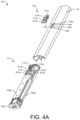
- FIG. 4 A is an exploded view illustrating features of a vaporizer body prior to assembly consistent with implementations of the current subject matter
- FIG. 5 A - FIG. 5 F illustrate features of an integrated board assembly and a printed circuit board assembly of a vaporizer device consistent with implementations of the current subject matter
- FIG. 6 A - FIG. 6 C illustrate features of antenna designs incorporated in a vaporizer device consistent with implementations of the current subject matter
- FIG. 12 illustrates features of a cartridge of a vaporizer device consistent with implementations of the current subject matter
- FIG. 15 A - FIG. 15 B illustrate features of various seals incorporated in a cartridge of a vaporizer device consistent with implementations of the current subject matter
- FIG. 17 illustrates features relating to assembly of a heater assembly and internal connections in a cartridge, consistent with implementations of the current subject matter
- FIG. 18 illustrates additional features relating to filling a cartridge with a vaporizable material consistent with implementations of the current subject matter
- FIG. 27 shows a fill path (arrow A) of vaporizable material entering the reservoir
- the controller 128 sends a signal to the haptics system 144 , instructing the haptics system 144 to provide haptic feedback (e.g., a vibration).
- the controller 128 could additionally or alternatively provide a signal to the speaker 140 to emit a sound or series of sounds.
- the haptics system 144 and/or speaker 140 may also provide control and usage feedback to the user of the vaporizer device 100 ; for example, providing haptic and/or audio feedback when a particular amount of a vaporizable material has been used or when a period of time since last use has elapsed.
- haptic and/or audio feedback may be provided as a user cycles through various settings of the vaporizer device 100 .
- light pipe components 117 a,b,c,d and the LEDs 136 are shown in a specific pattern, implementations of the current subject matter are not so limited. Fewer or additional LEDs, and a corresponding light pipe structure, may be incorporated in various patterns, arrangements, sizes, and shapes.
- the light pipe 147 may be placed into or inserted such that the light pipe components 117 a,b,c,d are placed within the openings 119 a,b,c,d on the outer shell 112 and the recesses 817 a,b,c,d of the mating structure 113 . Slight pressure placed on the light pipe 147 , to press the light pipe components 117 a,b,c,d into their respective openings, causes the light pipe 147 to break away from the carriage unit 147 a . The carriage unit 147 a may be discarded, and the individual light pipe components 117 a,b,c,d are flush-mounted within the outer shell 112 via installation as one unit.
- an upward extending edge 819 a,b,c,d may extend around a portion of the upper circumference of each recess 817 a,b,c,d .
- the upward extending edge 819 a,b,c,d may have a sloped surface extending upward and outward from the upper circumference of each recess 817 a,b,c,d .
- the upward extending edge 819 a,b,c,d may aid in installation of the light pipe components 117 a,b,c,d to achieve a smooth or flat position with respect to the outer shell 112 .
- the air inlets 116 a,b may include a plurality of individual air slots.
- the air inlet 116 a may be a grouping of circular, square, rectangular, triangular, oval, and/or other-shaped air slots arranged in a variety of configurations.
- the gasket 115 is installed at a proximal end of the assembled structure (i.e., the top and the bottom support structures 120 a , 120 b connected together), the entirety of which can then be slid into an outer shell 112 .
- the light pipe 147 may be added, as described above with respect to FIGS. 8 A- 8 D .
- FIG. 11 Q is a back cross-sectional view and FIG. 11 R is a side cross-sectional view, illustrating the bottom cap 120 c installed and connected on the connected structure (i.e., the top and the bottom support structures 120 a , 120 b connected together).
- connections and engagements are described with reference to assembling the components of the inner assembly 111 and the vaporizer body 110 , these connections and engagements are exemplary and non-limiting examples of how the various components may be assembled. For example, different types of snaps and engagements may be utilized and incorporated. In some instances as noted herein, snaps and connection mechanisms may not be incorporated and instead various components may fit within or connect to each other without snapping or connecting.
- FIGS. 32 A- 32 H illustrate features of the integrated board assembly 400 and the support structure in accordance with an alternative implementation of the current subject matter.
- FIG. 32 A is a top perspective view of a portion of the integrated board assembly 400 looking from the proximal end
- FIG. 32 B is a top perspective view of a portion of the integrated board assembly 400 looking from the distal end.
- the proximal end 402 a (at which the first antenna 143 is integrated) of the flexible layer 402 may extend from a proximal (e.g., front) end of the PCBA 126 , as shown in FIGS. 32 A and 32 B .
- the proximal end 402 a of the flexible layer 402 may extend outward from the proximal end of the PCBA 126 and curve or bend so that the planar surface (having a front surface and a back surface) of the first antenna 143 is positioned in a perpendicular configuration with respect to the top and bottom surfaces of the PCBA 126 .
- the proximal end 402 a of the flexible layer 402 may be curved approximately 180 degrees so that the planar surface of the first antenna 143 is properly oriented.
- the proximal end 402 a of the flexible layer 402 may be bent at one or more angles so that the planar surface of the first antenna 143 is properly oriented.
- Antenna through-holes 3202 a,b may extend through the planar surface of the first antenna 143 .
- the power pins 122 a,b may be positioned to extend through respective ones of the antenna through-holes 3202 a,b , and may be connected (e.g., soldered) to the back surface of the first antenna 143 .
- a support plate 3204 may be provided and may have a planar surface adjacent to and that aligns with that of the first antenna 143 .
- the support plate 3204 may include support openings 3206 a,b that align with the antenna through-holes 3202 a,b respectively, and the power pins 122 a,b extend through the support openings 3206 a,b .
- An opening 3208 on the top surface at the proximal end of the top support structure 120 a is sized and shaped to accommodate the proximal end 402 a of the flexible layer 402 in the configuration in which the proximal end 402 a extends from the proximal end of the PCBA 126 .
- a teething configuration on proximal ends of the top support structure 120 a and the bottom support structure 120 b is provided to allow for alignment and connection of the respective proximal ends.
- a teething configuration of the top support structure 120 a may include downward-extending protrusions 3210 a,b,c,d that mate (e.g., with a friction fit) with corresponding upward-extending openings (or gaps) 3220 a,b,c,d that are formed in the proximal end of the bottom support structure 120 b .
- the openings 3220 b,c may be sized and shaped to hold the power pins 122 a,b respectively, with the power pins 122 a,b extending longitudinally outward through the openings 3220 b,c .
- the corresponding protrusions 3210 b,c may be of a downward length sufficient to allow the power pins 122 a,b respectively to securely fit within the openings 3220 b,c and engage flexible side protrusions 3222 with for example a friction fit.
- the side protrusions 3222 may be formed on each side of the openings 3220 b,c and protrude inward in the respective openings 3220 b,c .
- the power pins 122 a,b contact the side protrusions 3222 upon a force being applied to the power pins 122 a,b , and the side protrusions releasably secure the power pins 122 a,b within the openings 3220 b,c below a bottom surface of the side protrusions 3222 .
- the side protrusions 3222 may be engaged by the respective power pins, causing the power pins 122 a,b to be pushed below the side protrusions 3222 , which serve to secure the power pins 122 a,b within the respective openings 3220 b,c.
- the first antenna 143 and the support plate 3204 are positioned on an outer side of the proximal end of the bottom structure 120 b .
- the configuration of the proximal end 402 a of the flexible layer 402 and the first antenna 143 as shown in FIGS. 32 A and 32 B , provides for the planar surface of the first antenna 143 to align with the proximal end of the bottom support structure 120 b.
- top support structure 120 a and the bottom support structure 120 b may then be connected by proper alignment and engagement of the respective teething configurations to align the proximal ends of the top and the bottom support structures 120 a , 120 b .
- outer side snaps 1122 a,b may engage side tabs 1124 a,b to secure the top and the bottom support structures 120 a , 120 b to one another.
- Outward-extending tabs 3224 may be provided on the proximal ends of the top support structure 120 a and the bottom support structure 120 b to provide one or more flat surfaces against which the back end of the support plate 3204 may contact.
- FIGS. 32 F and 32 G are top perspective views, looking from the proximal ends, showing the inner assembly 111 in which the integrated board assembly 400 is secured, the top and the bottom support structures 120 a , 120 b connected to one another, and the gasket 115 installed on the proximal end of the connected structure (i.e., the top and the bottom support structures 120 a , 120 b connected together).
- the connected structure and the gasket 115 are semi-transparent in FIG. 32 F to illustrate the placement of the various components with respect to these outer structures.
- the planar surface of the first antenna 143 aligns with the outer side of the proximal ends of the connected structure as shown in FIG. 32 F .
- the first antenna 143 is positioned adjacent to the front plate 1132 , the first antenna 143 is positioned or sandwiched (e.g., substantially parallel) between the front plate 1132 and the gasket 115 , with the power pins 122 a,b extending through the gasket 115 (e.g., through the gasket openings 115 f,g formed through the planar surface of the gasket 115 and configured to surround the power pins 122 a,b when the gasket 115 is installed on the connected structure as described with respect to FIG. 11 S ).
- the gasket 115 may additionally have a tab 3208 a extending from the lip 115 c of the gasket 115 to mate with the opening 3208 on the top surface at the proximal end of the top support structure 120 a.
- the antenna configuration shown in FIGS. 32 A- 32 H provides an improved mounting for the power pins 122 a,b as the power pins 122 a,b extend lengthwise through both the support openings 3206 a,b of the support plate 3204 and the antenna through-holes 3202 a,b . This results in increased support for the power pins 122 a,a . Moreover, the orientation of the proximal end 402 a of the flexible layer 402 provides for more efficient use of space of the PCBA 126 during manufacturing.
- FIGS. 33 A- 33 E illustrate features of the integrated board assembly 400 and the support structure of a vaporizer device consistent with additional implementations of the current subject matter in which the proximal end 402 a of the flexible layer 402 extends from a side region of the PCBA 126 and in which the first antenna 143 is oriented such that it is positioned external to the connected structure, as described with reference to FIGS. 33 A- 33 E .
- FIG. 33 A is a top perspective view of a portion of the integrated board assembly 400 looking from the proximal end
- FIG. 33 B is a top perspective view of a portion of the integrated board assembly 400 looking from the distal end.
- the planar surface of the first antenna 143 is aligned with the proximal end of the PCBA 126 (e.g., side edges of the planar surface of the first antenna 143 align with side edges of the proximal end of the PCBA 126 ).
- FIG. 33 C is a top perspective view showing alignment of the top support structure 120 a , the integrated board assembly 400 , and the bottom support structure 120 b , looking from the proximal ends of each.
- Features of the top support structure 120 a and the bottom support structure 120 b may be similar or equivalent to those described elsewhere in the description.
- the teething configuration of the proximal ends of the top support structure 120 a and the bottom support structure 120 b configured to allow for alignment and connection of the respective proximal ends, may be similar to that shown in FIGS. 32 C and 32 D .
- the first antenna 143 is positioned on an outer side of the proximal end of the bottom structure 120 b .
- the configuration of the proximal end 402 a of the flexible layer 402 and the first antenna 143 as shown in FIGS. 33 A and 33 B , provides for the planar surface of the first antenna 143 to align with the proximal end of the bottom support structure 120 b.
- top support structure 120 a and the bottom support structure 120 b may then be connected by alignment and engagement of the respective teething configurations to align the proximal ends of the top and the bottom support structures 120 a , 120 b .
- outer side snaps 1122 a,b may engage side tabs 1124 a,b to secure the top and the bottom support structures 120 a , 120 b to one another.
- FIG. 33 D is a top perspective view, looking from the proximal end, showing the inner assembly 111 in which the integrated board assembly 400 is secured, the top and the bottom support structures 120 a , 120 b connected to one another, and the gasket 115 installed on the proximal end of the connected structure.
- the connected structure and the gasket 115 are semi-transparent in FIG. 33 D to illustrate the placement of the various components with respect to these outer structures.
- gasket 115 may be similar to those described with respect to FIGS. 11 S, 11 T, and 32 F .
- the first antenna 143 is sandwiched (e.g., substantially parallel to) or positioned between the front plate 1132 and the gasket 115 , with the power pins 122 a,b extending lengthwise through the gasket 115 .
- FIG. 33 E is a cross-sectional side view showing a portion of the vaporizer device 100 with the cartridge 150 inserted into the cartridge receptacle 114 formed by the outer shell 112 of the vaporizer body 110 in which the inner assembly 111 is inserted.
- the portion shown includes the distal end of the cartridge 150 , on or near which the data tag 164 is positioned, and the proximal end of the inner assembly 111 at which the first antenna 143 is positioned between the gasket 115 and the proximal end of the connected structure 120 a,b .
- this configuration results in a reduced spacing 3330 between the data tag 164 and the first antenna 143 which advantageously results in improved communication between the cartridge 150 and the vaporizer body 110 .
- the side protrusions 3222 may be formed on each side of the openings 3220 b,c and protrude inward in the respective openings 3220 b,c .
- the power pins 122 a,b contact the side protrusions 3222 upon a force being applied to the power pins 122 a,b , and the side protrusions releasably secure the power pins 122 a,b within the openings 3220 b,c below a bottom surface of the side protrusions 3222 .
- a portion of the proximal end of the bottom support structure 120 b forms a support wall 3226 positioned between the openings 3220 b,c .
- the support wall 3226 is sized and shaped to provide support between the openings 3220 b,c such that this portion of the proximal end of the bottom support structure 120 b does not flex or otherwise bend, thus providing additional support for the power pins 122 a,b and the first antenna 143 .
- the support wall 3226 may have for example a cross-shaped cross-section or other cross-section of a suitable configuration and thickness (e.g., rectangular, x-shaped, etc.) to provide a supportive wall between the openings 3220 b,c .
- FIG. 39 A is a bottom perspective view of the distal end of the top support structure 120 a (the end at which the bottom cap 120 c is connected) consistent with implementations of the current subject matter.
- a cap connection region 3920 is at the distal end of the top support structure 120 a , and it is the cap connection region 3920 which fits within the inner cap region 120 d of the bottom cap 120 c (see also FIGS. 4 B and 11 N ).
- Adjacent to the cap connection region is a cross support bar 3902 that extends longitudinally across the width of the top support structure 120 a , as shown in FIG. 39 A .
- FIG. 39 B is a cross-sectional front view of the cross support bar 3902 .
- Two openings 3904 a,b are formed through the top support structure 120 a and are adjacent the cross support bar 3902 on the side opposite the cap connection region 3920 moving away from the distal end. Consistent with implementations of the current subject matter, the two openings 3904 a,b may be separated by a cross rib 3906 that extends down from an upper portion of the cross support bar 3902 to separate the two openings 3904 a,b and to connect to the top support structure 120 a .
- the configuration of the two openings 3904 a,b and the cross rib 3906 may aid in material flow during injection molding of the top support structure 120 a , thereby reducing warped regions that may otherwise occur.
- FIG. 39 D is a top perspective view of the proximal end of the top support structure 120 a .
- various crush ribs may be incorporated on surfaces of the inner assembly 111 , including the top support structure 120 a , the bottom support structure 120 b , and the bottom cap 120 c , to aid in providing a secure and tight fit within the outer shell 112 .
- the crush ribs engage an inner surface of the outer shell 112 when in contact with the outer shell 112 , which provides for a secure and tight fit. As shown in FIG.
- top support structure crush ribs 3910 a,b are provided on a top surface of the top support structure 120 a near the proximal end to assist in securing the top support structure 120 a within the outer shell 112 during installation of the light pipe components 117 .
- a process flow chart 2800 illustrates features of a method, which may optionally include some or all of the following.
- the integrated board assembly 400 is inserted into the bottom support structure 120 b .
- the PCBA 126 portion of the integrated board assembly 400 may be snapped into the bottom support structure by engaging one or more snaps 1102 a,b,c .
- 2802 may also include alignment and insertion of the power pins 122 a,b with and into respective openings, for example the teeth configuration described with reference to FIG. 11 D , at a proximal end of the bottom support structure 120 b.
- the bottom cap 120 c is connected to the connected structure at the distal end thereof.
- the side snap engagement component 1128 of the bottom cap may engage the distal side snap 1126 of the bottom support structure 120 b upon the bottom cap 120 c being aligned with and inserted on the distal end of the connected structure.
- the vaporizer device 100 includes the cartridge 150 configured to operatively couple with the vaporizer body 110 .
- the cartridge 150 is disposable whereas the vaporizer body 110 is durable and/or re-usable.
- the cartridge 150 may also be configured to be reused as described elsewhere herein.
- FIGS. 12 - 14 illustrate features of a cartridge 150 of a vaporizer device 100 consistent with implementations of the current subject matter.
- the cartridge 150 may include the cartridge body 156 defining, at least in part, a reservoir 158 configured to contain vaporizable material, a mouthpiece 152 , and a vaporizing assembly of vapor-generating components positioned within the cartridge body 156 and configured to vaporize the vaporizable material.
- a reservoir 158 configured to contain vaporizable material
- a mouthpiece 152 a vaporizing assembly of vapor-generating components positioned within the cartridge body 156 and configured to vaporize the vaporizable material.
- the cartridge body 156 can be divided, generally, into a proximal end region 156 A, a central region 156 B, and a distal end region 156 C.
- the proximal end region 156 A of the cartridge body 156 can be coupled to the mouthpiece 152 configured to deliver the vapor to the user.
- the central region 156 B includes a tank or reservoir 158 defined, at least in part, by the cartridge body 156 and configured to contain an amount of the vaporizable material.
- the distal end region 156 C of the cartridge body 156 may house one or more components configured to vaporize the material from the reservoir 158 into a vaporization chamber 1005 .
- the mouthpiece 152 is configured to interface with the user to release the vapor from the vaporization chamber 1005 to the user through one or more openings 154 in the mouthpiece 152 , for example, upon the user drawing a breath through the vaporizer device 100 .
- Each of these components will be described in more detail below.
- the vaporizable material is cannabis oil.
- Cannabis oils can present particular challenges when vaporized using a cartridge and a vaporizer device.
- cannabis oil is relatively sticky and viscous, particularly once it dries out.
- leakage may be a more serious consideration and challenge compared to other aqueous vaporizable materials.
- leakage of cannabis oil may result in clogging of the device and disturbing the electrical components, particularly the electrical contacts.
- the dried oil can also disrupt the electrical control of the vaporizer device due to its electrically insulating properties.
- the distal end region 156 C of the cartridge body 156 may be configured to couple to and be secured with the vaporizer body 110 , for example, by inserting within the cartridge receptacle 114 (see FIGS. 4 A- 4 B ).
- the cartridge receptacle 114 may have a proximal opening and an inner diameter sufficient to receive the outer diameter of the distal end region 156 C of the cartridge body 156 .
- the cartridge receptacle 114 may have a depth sufficient to slide the cartridge body 156 into the cartridge receptacle 114 up to about the level of the mouthpiece 152 .
- the distal end region 156 C of the cartridge body 156 may include substantially straight or inwardly tapered sides and include one or more coupling features that secure the cartridge 150 within the cartridge receptacle 114 of the vaporizer body 110 .
- the one or more coupling features may be configured to engage with a complementary feature on the vaporizer body 110 , such as within the cartridge receptacle 114 , when the cartridge 150 engages with the vaporizer body 110 .
- the one or more coupling features may be male parts such as a pair of tabs or a circumferential rib on an outer surface of the distal end region 156 C of the cartridge body 156 that inserts within a complementary female part such as a pair of indents or a circumferential groove on an inner surface of the cartridge receptacle 114 .
- the male parts may snap into the female parts upon downward insertion of the cartridge 150 within the cartridge receptacle 114 to provide a secure fit and reversed upon withdrawing the cartridge 150 upward out of the cartridge receptacle 114 .
- the one or more coupling features is a circumferential rib on an outer surface of the cartridge 150 , for example, near where proximal end region 156 A meets the central region 156 B (see FIG. 13 ).
- the circumferential rib may be an elastomeric element configured to provide an interference fit with an inner surface of the cartridge receptacle 114 such that the cartridge 150 securely couples with the vaporizer body 110 without needing to engage with a corresponding feature on the inner surface of the cartridge receptacle 114 (see, for example, FIG. 4 A ).
- the depth of the cartridge 150 is also measured transverse the longitudinal axis A, but along the minor axis of the cartridge 150 and thus refers to the length of the shorter sides.
- the width may be 1.2 times, 1.3 times, 1.4 times, 1.5 times, 1.6 times, 1.7 times, 1.8 times, 1.9 times, etc. or greater than the depth.
- the cartridge 150 may be between about 1 cm and 10 cm long, between about 2 cm and 7 cm long, between 3 cm and 5 cm long.
- the length of the cartridge 150 may be less than 8 cm, less than 7 cm, less than 6 cm, less than 5.5 cm, less than 5 cm, etc.
- the cartridge 150 may have a total length of about 3.3 cm, a width (i.e., across the major axis of the cartridge) of about 1.7 cm, and a depth (i.e., across the minor axis of the cartridge) of about 0.85 cm.
- the cross-sectional shape of the cartridge body 156 may be any of a variety of shapes, including circular, round, or non-round shapes, such as an approximately oval, elliptical, rectangular, square, trapezoidal, or other cross-sectional shape.
- the cross-sectional shape may be geometric or free-form shape. Non-round shapes, particularly flattened shapes may be preferred to prevent rolling when the vaporizer device 100 is placed on its side.
- the shape of the cartridge 150 including the cartridge body 156 and the mouthpiece 152 , resembles or is a continuation of the general shape of the vaporizer body 110 such that upon coupling the cartridge 150 and the vaporizer body 110 together, the vaporizer device 100 has a substantially sleek profile.
- the coupling between the cartridge 150 and the vaporizer body 110 may allow for the vaporizer device 100 to have continuous edges that provide a seamless unibody profile from end to end.
- the coupling between the cartridge 150 and the vaporizer body 110 may occur upon relative sliding along the longitudinal axis A of the vaporizer device 100 as shown at FIG. 13 .
- other relative movements are considered herein, such as rotation around the longitudinal axis A or side-to-side movements orthogonal to the longitudinal axis A of the vaporizer device 100 .
- the cartridge receptacle 114 and the cartridge 150 have bilateral symmetry such that the cartridge 150 may be flipped horizontally relative to the cartridge receptacle 114 and still operatively couple with the vaporizer body 110 .
- the cartridge receptacle 114 and cartridge 150 have lateral dissymmetry such that they engage with one another in only a single orientation.
- the fit between the cartridge body 156 and the vaporizer body 110 may be sufficient to provide a secure fit to prevent inadvertent uncoupling, but may still allow for the cartridge 150 to be easily withdrawn or disengaged from the vaporizer body 110 to remove and replace the cartridge 150 .
- the engagement between the cartridge body 156 and the vaporizer body 110 may include a release button or other feature that is configured to actively disengage the cartridge 150 from the device.
- the outer surface of the cartridge 150 may incorporate one or more three-dimensional features such as slots, knurling, or other type of finger grips that aid a user during installation and removal of the cartridge 150 from the vaporizer body 110 .
- the coupling such as a snap-fit coupling, may provide a visual, audible and/or tactile confirmation that the cartridge body 156 is positioned properly relative to the vaporizer body 110 .
- the second sealing rib 1035 may provide a snap-fit with the cartridge receptacle 114 when inserted within the cartridge receptacle 114 . It should be appreciated that the position of the mouthpiece seal 177 relative to the mouthpiece 152 may vary. Additionally, the mouthpiece 152 may incorporate more than the mouthpiece seal 177 , for example, the mouthpiece seal 177 near the distal end region 1030 as well as a seal (such as an O-ring) closer to the proximal end 153 of the mouthpiece 152 .
- the shape of the pad along with its wedged coupling with the internal flange 1045 of the mouthpiece, the proximal surface 1050 and upper element 1052 of the cartridge body 156 prevent shifting of the pad 170 during use and handling. Shifting of the pad 170 may cause the pad 170 to obstruct vapor flow through the device.
- FIG. 34 D is a perspective, front cross-sectional view of the cartridge 150 with the two pads 170 a,b inserted in the cartridge body 156 and with the mouthpiece 152 attached to the proximal end region 156 A of the cartridge body 156 .
- FIG. 34 E is a cross-sectional view of the cartridge 150 taken along a plane shown by arrows A-A of FIG. 12
- FIG. 34 F is a front perspective view thereof.
- the central, upper element 1052 has a side cross-sectional profile with a sharpened end, curved and angled sides, and a blunt top that splits, due to the sharpened end and the curved and angled sides, the flow of vapor around the central, upper element 1052 for larger particles to be captured and entrained by the pads 170 a,b , which are off-axis with respect to direction of the vapor flow.
- the central, upper element 1052 may be an airfoil with a leading edge and a closed trailing edge.
- the side cross-sectional profile of the central, upper element 1052 may be parabolic or triangular, as shown in FIG. 35 A as well as FIGS.
- a bounding box defining the side cross-sectional area of the central, upper element 1052 may have a length of about 1.5 mm, about 1.6 mm, about 1.7 mm, about 1.8 mm, about 1.9 mm, up to about 2.0 mm, and may have a height of about 2.0 mm, about 2.1 mm, about 2.2 mm, about 2.3 mm, about 2.4 mm, about 2.5 mm, about 2.6 mm, up to about 2.7 mm.
- the sealing ring 171 may be an elastomeric material configured to be compressed slightly upon insertion of the central cannula 172 into the central channel 1015 thereby providing fluid sealing and preventing the vaporizable fluid stored in the reservoir 158 from exiting the cartridge 150 through the central channel 1015 .
- Distal end region 156 C of the cartridge body 156 and the mouthpiece 152 are both shown as opaque and blocking from view any of the internal components contained within either of those regions. From a usability perspective, a user of the vaporizer device 100 may want to see a remaining amount of vaporizable material 187 within the reservoir 158 , but not be distracted with the complexity of the internal components of the cartridge body 156 .
- the translucent to transparent central region 156 B may reveal the amount of vaporizable material remaining in the reservoir 158 .
- An opaque plastic may be injection-molded directly over a clear plastic, with the opaque plastic region hiding from view internal components of the cartridge body 156 and the clear plastic region showing a large volume of the reservoir 158 portion of the cartridge body 156 (see also FIGS. 16 A- 16 B ).
- the opaque plastic may be laser-etched to provide a label directly on the cartridge body 156 .
- the cartridge body 156 may include graduations positioned relative to the central region 156 B to provide a user with an indication as to the volume of vaporizable material 187 contained within the reservoir 158 .
- the central cannula 172 extending through the reservoir 158 defines the vaporization chamber 1005 that together with the central channel 1015 directs vapor flow towards the mouthpiece 152 .
- the central cannula 172 defining the vaporizing chamber may be a generally cylindrical element extending from a bottom plate 1072 to the proximal tap 1018 .
- the central cannula 172 may extend coaxial with the longitudinal axis A of the cartridge 150 up through the reservoir 158 such that the reservoir 158 surrounds the central cannula 172 .
- the base region of the vaporization chamber 1005 may have an enlarged volume and a greater inner diameter compared to an inner diameter of the proximal tap 1018 .
- the bottom plate 1072 may include a central aperture 1073 such that the vaporization chamber 1005 remains open on a distal end to provide a vapor flow passageway through the cartridge body 156 to the mouthpiece 152 .
- the central aperture 1073 may be elongated such that it forms an oval, elliptical, or other elongate shape having a minor axis and a major axis.
- a middle portion of the central aperture 1073 may be aligned with the vaporization chamber 1005 and at least partially encircled by the central cannula 172 .
- the middle portion of the central aperture 1073 may be generally rounded or circular in shape similar to a cross-sectional shape of the base of the central cannula 172 .
- the heater 166 of the vaporizing assembly may cause the vaporizable material to be converted from a condensed form (e.g., a solid, a liquid, a solution, a suspension, a part of an at least partially unprocessed plant material, etc.) to the gas phase.
- a condensed form e.g., a solid, a liquid, a solution, a suspension, a part of an at least partially unprocessed plant material, etc.
- At least some of the gas-phase vaporizable material may condense to form particulate matter in at least a partial local equilibrium with the gas phase as part of an aerosol, which may form some or all of an inhalable dose provided by the vaporizer for a given puff or draw on the vaporizer.
- the interplay between gas and condensed phases in an aerosol generated by a vaporizer may be complex and dynamic, as factors such as ambient temperature, relative humidity, chemistry, flow conditions in airflow paths (both inside the vaporizer and in the airways of a human or other animal), mixing of the gas-phase or aerosol-phase vaporizable material with other air streams, etc., may affect one or more physical parameters of an aerosol.
- the inhalable dose may exist predominantly in the gas phase (i.e., formation of condensed phase particles may be very limited).
- Vaporizers for use with liquid vaporizable materials typically include an atomizer in which a wicking element (also referred to herein as a wick 168 ), which may include any material capable of causing passive fluid motion, for example, by capillary pressure) conveys an amount of a liquid vaporizable material to a part of the atomizer that includes the heating element.
- the wicking element is generally configured to draw liquid vaporizable material from the reservoir configured to contain (and that may in use contain) the liquid vaporizable material such that the liquid vaporizable material may be vaporized by heat delivered from the heating element.
- the heater 166 may be or include one or more of a conductive heater, a radiative heater, and a convective heater.
- a vaporizing heating element is a resistive heating element, which may be constructed of or at least include a material (e.g., a metal or alloy, for example a nickel-chromium alloy, or a non-metallic resistor) configured to dissipate electrical power in the form of heat when electrical current is passed through one or more resistive segments of the heating element.
- an atomizer may include a vaporizing heating element that includes resistive coil or other heating element wrapped around, positioned within, integrated into a bulk shape of, pressed into thermal contact with, or otherwise arranged to deliver heat to a wicking element to cause a liquid vaporizable material drawn by the wicking element from a reservoir to be vaporized for subsequent inhalation by a user in a gas and/or a condensed (e.g., aerosol particles or droplets) phase.
- a vaporizing heating element that includes resistive coil or other heating element wrapped around, positioned within, integrated into a bulk shape of, pressed into thermal contact with, or otherwise arranged to deliver heat to a wicking element to cause a liquid vaporizable material drawn by the wicking element from a reservoir to be vaporized for subsequent inhalation by a user in a gas and/or a condensed (e.g., aerosol particles or droplets) phase.
- Certain vaporizers may also or alternatively be configured to create an inhalable dose of gas-phase and/or aerosol-phase vaporizable material via heating of a non-liquid vaporizable material, such as for example a solid-phase vaporizable material or plant material containing the vaporizable material.
- a resistive heating element may be part of or otherwise incorporated into or in thermal contact with the walls of an oven or other heating chamber into which the non-liquid vaporizable material is placed.
- a resistive heating element or elements may be used to heat air passing through or past the non-liquid vaporizable material to cause convective heating of the non-liquid vaporizable material.
- a resistive heating element or elements may be disposed in intimate contact with plant material such that direct conductive heating of the plant material occurs from within a mass of the plant material (e.g., as opposed to only by conduction inward from walls of an oven).
- the wick 168 may be formed of any of a variety of materials, including metals, polymer, natural fibers, synthetic fibers, or combinations of these.
- the wick 168 may be formed of silica fibers, cotton, ceramic, hemp, stainless steel mesh, rope cables, and/or any porous medium, such as for example sintered glass beads.
- the wick 168 is porous and provides a capillary pathway for fluid within the reservoir 158 through and into the wick 168 .
- the capillary pathway is generally large enough to permit wicking of sufficient material to replace vaporized liquid transferred from the reservoir 158 by capillary action (wicking) during vaporization, but may be small enough to prevent leakage of the vaporizable material out of the cartridge during normal operation, including when pressure is applied to outside the cartridge 150 .
- the wick 168 may have a size configured to handle high viscosity liquids. In some implementations, the wick 168 may have a diameter that is at least about 1.5 mm.
- the wick may be larger than 1.5 mm in diameter (e.g., about 1.9 mm or larger, about 2.0 mm or larger, about 2.1 mm or larger, about 2.2 mm or larger, about 2.3 mm or larger, about 2.4 mm or larger, about 2.5 mm or larger, etc., including between about 1.8 mm and about 5 mm, between about 1.9 mm and about 4 mm, between about 2 mm and about 4 mm, etc.).
- the material of the wick 168 is configured to draw the liquid vaporizable material from the reservoir 158 into the vaporization chamber 1005 without the need for a pump or other mechanical moving part.
- the tension of the heating coil 167 wound around the wick 168 may vary.
- Winding the heating coil 167 tighter and/or with additional windings may create a larger heating surface area to create more intense or concentrated heating of the vaporizable material. Likewise, reducing the diameter of the wick may also create more intense or concentrated heating of the vaporizable material.
- Alternative configurations may include gravity-fed, capillary-fed, micro-pump, or collapsible bladders which operate under pressure differentials.
- the heater 166 is described herein as incorporating a heating coil, it should be appreciated that other configurations may be used and that the resistive element need not be shaped as a coil. The heater 166 also need not be a coil/wick configuration. In some implementations, the heater 166 incorporates a piezo aerosolizer to generate droplets of the vaporizable material.
- the heating coil 167 may be a resistance wire wrapped around the wick 168 and connected to a positive and negative pole of a current source.
- the coil 167 may increase in temperature as a result of the current flowing through the wire to generate heat.
- the heat may be transferred to at least a portion of the vaporizable material through conductive, convective, and/or radiative heat transfer such that at least a portion of the vaporizable material vaporizes. Air drawn into the vaporization chamber 1005 may carry the vapor away from the heater 166 .
- the heater 166 may extend across the air path within the vaporization chamber 1005 , such as in a transverse direction. Still with respect to FIGS. 13 - 14 and also FIG. 17 , the central cannula 172 may be arranged coaxial with the longitudinal axis A of the device and the wick 168 may extend orthogonal to the longitudinal axis A through the central cannula 172 . The wick 168 is preferably positioned near a distal-most end region of the reservoir 158 such that the vaporizable material in the reservoir 158 may be fully used. A pair of lateral openings 1074 a,b may extend through the walls of the central cannula 172 near its base where the central cannula 172 couples to the bottom plate 1072 .
- the pair of lateral openings 1074 a,b may be aligned across from one another on opposing sides of the central cannula 172 .
- the openings 1074 a,b are provided and sized for coupling to the heater 166 .
- the bottom plate 1072 and the central aperture 1073 extending through the bottom plate 1072 may have a major axis and a minor axis.
- the elongate shape of the central aperture 1073 provides for two outer portions along the major axis of the bottom plate 1072 to extend beyond the base of the central cannula 172 .
- the two outer portions of the central aperture 1073 may be aligned with the lateral openings 1074 a,b of the central cannula 172 thereby forming an enlarged slot near the base of the central cannula 172 where it couples with the bottom plate 1072 .
- the wick 168 may extend through these lateral openings 1074 a,b and within this slot.
- the wick 168 of the heater 166 may include a central portion 1060 and opposing ends 1065 a,b .
- the heating coil 167 may be wrapped around the central portion 1060 of the wick 168 , which in turn may be positioned within the vaporization chamber 1005 .
- the opposing ends 1065 a,b of the wick 168 may be positioned outside the vaporization chamber 1005 by extending laterally outward through the lateral openings 1074 a,b of the central cannula 172 .
- the opposing ends 1065 a,b may be positioned within the internal volume of the reservoir 158 whereas the central portion 1060 of the wick 168 wrapped by the heating coil 167 may be positioned inside the vaporization chamber 1005 of the central cannula 172 .
- the leads 1067 of the heating coil 167 may extend away from the central portion 1060 of the wick 168 and down through the central aperture 1073 of the bottom plate 1072 out of the vaporization chamber 1005 .
- the leads 1067 may extend into the distal end region 156 C of the cartridge body 156 where the leads 1067 may electrically couple with the power pin receptacles 160 a,b , which will be described in more detail below.
- the distal end region 156 C of the cartridge body 156 may house the internal sealing gasket 173 coupled to a lower support structure 174 .
- the internal sealing gasket 173 may be positioned generally under the bottom plate 1072 of the central cannula 172 and attached to an upper surface of the lower support structure 174 . This placement of the internal sealing gasket 173 serves to seal the reservoir 158 on the distal or bottom end and thereby reduce or eliminate leaking of vaporizable material out of the reservoir 158 , for example, into the electrical components contained in the distal end region 156 C of the cartridge 150 as well as the vaporizer body 110 .
- the internal sealing gasket 173 may be, in some implementations, an oversized elastic or rubberized material that plugs various openings in a distal end region of the device and forms a seal between the reservoir 158 and the lower support structure 174 when under compression.
- the internal sealing gasket 173 may be sized and shaped to fit between the reservoir 158 and the lower support structure 174 to seal any openings therebetween.
- the distal extensions of the central cannula 172 projecting from the lower surface of the bottom plate 1072 extend down through the central opening 195 of the internal sealing gasket 173 .
- the leads 1067 of the heating coil 167 may extend away from the central portion 1060 of the wick 168 and down through the central aperture 1073 of the bottom plate 1072 and through the central opening 195 of the internal sealing gasket 173 in order to electrically couple with the power pin receptacles 160 a,b , within the lower support structure 174 which will be described in more detail below.
- the surface features 197 a,b may project through the outer portions of the central aperture 1073 of the bottom plate 1072 .
- the middle portion of the central aperture 1073 is aligned with the longitudinal axis A of the cartridge and at least partially encircled by the central cannula 172 .
- the central aperture 1073 may additionally include two outer portions on either side of the middle portion that are positioned generally outside the perimeter of the central cannula 172 base (i.e., along the major axis of the plate).
- the pair of surface features 197 a,b projecting from the upper surface of the internal sealing gasket 173 extends up through the outer portions of the central aperture 1073 on either side of the central cannula 172 thereby sealing these outer portions of the central aperture 1073 .
- the distal extensions of the central cannula 172 on the lower surface of the bottom plate 1072 may extend down through the central opening 195 in the internal sealing gasket 173 . This provides a tight fit coupling between the bottom plate 1072 of the central cannula 172 and the internal sealing gasket 173 .
- the pair of surface features 197 a,b projecting from the upper surface of the internal sealing gasket 173 may include a region configured to interface with and laterally support the heater 166 .
- the opposing ends 1065 a,b of the wick 168 extending through the lateral openings 1074 a,b may engage with at least a portion of the pair of surface features 197 a,b .
- the pair of surface features 197 a,b may also seal with the wick 168 .
- the pair of surface features 197 a,b may generally align with the location of the lateral openings 1074 a,b of the central cannula 172 through which the opposing ends 1065 a,b of the wick 168 extend.
- the wick 168 may extend orthogonal to the longitudinal axis A at the base of the reservoir 158 .
- the opposing ends 1065 a,b of the wick 168 may be positioned within the reservoir 158 and the central portion 1060 of the wick 168 wound by the heating coil 167 may be positioned within the vaporization chamber 1005 .
- the upper half of the wick 168 may be sealed by the walls of the central cannula 172 defining the lateral openings 1074 a,b .
- the lower half of the wick 168 may engage and seal with the pair surface features 197 a,b of the internal sealing gasket 173 .
- the pair of surface features 197 a,b may be sized and shaped to insert through the central aperture 1073 of the bottom plate 1072 helping to seal the central aperture 1073 (see FIGS. 17 , 19 A- 19 B ). At least a portion of the pair of surface features 197 a,b extends a distance toward the opposing ends 1065 a,b of the wick 168 .
- This portion of the pair of surface features 197 a,b may include a wick mating surface sized and shape to complement the cylindrical surface of the wick 168 .
- the portion may have a semi-circular wick mating surface configured to seal with the cylindrical outer surface of a region of the wick 168 .
- the portion of the pair of surface features 197 a,b may also laterally support the opposing ends 1065 a,b of the wick 168 .
- the internal sealing gasket 173 also may include a midline region between the upper and lower regions.
- the midline region of the internal sealing gasket 173 may seal with the internal surface of the cartridge body 156 .
- the midline region of the internal sealing gasket 173 may be encircled by a seal having dual sealing beads 198 .
- the dual sealing beads 198 are configured to provide a circumferential seal with the distal end region 156 C of the cartridge body 156 (see FIG. 19 B ).
- the dual sealing bands 198 may be provided for redundancy, to prevent vaporizable material from leaking from the reservoir 158 .
- the lower region of the internal sealing gasket 173 may include a pair of penetrable surface features 196 a,b projecting downward from the lower surface of the internal sealing gasket 173 .
- the pair of penetrable surface features 196 a,b extend distally and insert within corresponding ones of the pair of openings 1080 in the upper surface of the lower support structure 174 , as will be described in more detail below.
- the various features of the internal sealing gasket 173 on the upper, lower, and perimeter surfaces form an integrated sealing element that may seal a variety of locations within the cartridge 150 (i.e., the filling ports, the wick, and the distal end of the reservoir 158 ).
- the integrated seals provided by the internal sealing gasket 173 may simplify assembly and manufacturing, as will be described in more detail below.
- the distal end region 156 C of the cartridge body 156 may house the lower support structure 174 .
- the lower support structure 174 may include an upper region 1077 and a lower region 1078 (see FIGS. 19 B , FIG. 20 C , and FIG. 21 A ).
- the upper region 1077 is configured to mate with the lower region of the internal sealing gasket 173 .
- the upper region 1077 may include the pair of openings 1080 in the upper surface that are sized and shaped to receive the pair of penetrable surface features 196 a,b projecting downward from the lower surface of the internal sealing gasket 173 .
- the upper region 1077 of the lower support structure 174 may also include a central aperture 1079 extending through its thickness that is configured to align with the central opening 195 of the internal sealing gasket 173 that, in turn, aligns with the central aperture 1073 extending through the bottom plate 1072 .
- the central aperture 1073 in the bottom plate 1072 , the central opening 195 in the internal sealing gasket 173 , and the central aperture 1079 of the lower support structure 174 are configured to receive distal extensions of the central cannula 172 and align with the vaporization chamber 1005 to allow for air flow through the distal end region 156 C of the cartridge body 156 .
- a pair of air flow channels 1085 may extend through the lower support structure 174 .
- the air flow channels 1085 each communicate on a distal end with a respective one of a pair of the air flow inlets 162 a,b configured to remain in fluid communication with the atmosphere during use of the device.
- the distal end of the lower support structure 174 may define the air flow inlets 162 a,b into the air flow channels 1085 extending through the lower support structure 174 .
- the air flow channels 1085 extend from the air flow inlets 162 a,b through the lower region 1078 of the lower support structure into the upper region 1077 of the lower support structure 174 .
- the air flow channels 1085 extend to the pair of openings 1080 in the upper region 1077 of the lower support structure 174 .
- the pair of air flow channels 1085 may extend through the entire thickness of the lower support structure 174 between the air flow inlets 162 a,b in the lower surface to the pair of openings 1080 in the upper surface.
- the internal sealing gasket 173 may be positioned in the distal end region 156 C of the cartridge body 156 providing sealing between the reservoir 158 and the air flow channels 1085 of the lower support structure 174 .
- the pair of air flow inlets 162 a,b through the lower surface of the lower support structure 174 into the air flow channels 1085 remain unobstructed.
- the air flow inlets 162 a,b may align with or be positioned in fluid communication with the side air inlets 116 a,b , which will be described in more detail below.
- Each of the air flow channels 1085 extending through the lower support structure 174 from the lower air flow inlets 162 a,b to the pair of openings 1080 may additionally include a side channel outlet 1087 .
- the side channel outlet 1087 may be positioned a distance distal to the pair of penetrable surface features 196 a,b projecting into the air flow channels 1085 and a distance proximal to the lower air flow inlets 162 a,b into the air flow channels 1085 .
- the length of the air flow channels 1085 allows for the positioning of these side channel outlets 1087 away from the lower air flow inlets 162 a,b such that, in the event of a leak into the bottom volume of the cartridge body 156 , the air flow channels 1085 avoid being significantly filled in a manner that could block the air flow through or cause leaking out of the side channel outlets 1087 .
- FIGS. 20 A- 20 C illustrate air flow path 181 through the cartridge 150 upon coupling the cartridge 150 to a vaporizer body 110 .
- the outer shell 112 of the cartridge receptacle 114 of the vaporizer body 110 may include one or more side air inlets 116 a,b (see also FIGS. 1 C and 1 D ).
- the air inlets 116 a,b may be aligned with or positioned in fluid communication with the lower air flow inlets 162 a,b leading into the air flow channels 1085 from the lower region 1078 of the lower support structure 174 .
- Air may enter the cartridge 150 through the air inlets 116 a,b and continue through the lower air flow inlets 162 a,b and into the air flow channels 1085 of the lower region 1078 of the lower support structure 174 .
- FIGS. 20 A- 20 C and also FIGS. 18 , 19 A- 19 B show air may pass from the air flow channels 1085 of the lower region 1078 of the lower support structure 174 through the side channel outlets 1087 before passing up through the upper region 1077 into the vaporization chamber 1005 .
- the lower support structure 174 may act as a plenum for the air, which is then directed through the central opening 195 in the internal sealing gasket 173 , past the wick 168 and heating coil 167 , and through the vaporization chamber 1005 of the central cannula 172 .
- the air flow path 181 may continue through the opening 1022 of the proximal tap 1018 , into the central channel 1015 of the proximal end region 156 A of the cartridge body 156 and out the opening 154 of the mouthpiece 152 .
- the vapor may then be inhaled by a user.
- the mouthpiece 152 may incorporate a baffle 1088 near the opening 154 to allow the vapor to cool via a longer, turbulent flow path before entering the mouth of a user (see FIG. 20 B ).
- the lower region 1078 of the lower support structure 174 is configured to mate with the distal end region 156 C of the cartridge body 156 .
- the lower region 1078 of the lower support structure 174 may include a bottom tank seal 176 extending circumferentially around its perimeter (see FIGS. 15 C, 18 D , and 22 A).
- the bottom tank seal 176 may further block any material that leaks from the wick 168 into the distal end region 156 C of the cartridge body 156 from leaking out of the cartridge body 156 .
- the bottom tank seal 176 may be over-molded around the distal end of the lower region 1078 .
- the internal sealing gasket 173 and the lower support structure 174 may provide redundant sealing to prevent liquid leaks from the reservoir.
- the internal sealing gasket 173 positioned in a distal end region 156 C of the cartridge body 156 may include an upper region configured to seal a bottom end of the reservoir 158 , a midline region that may include the first circumferential perimeter seal (e.g. 198 ) that is configured to seal with an inner surface of the cartridge body 156 , and a lower region.
- the lower support structure 174 may also be positioned in the distal end region 156 C of the cartridge body 156 .
- the lower support structure 174 may include the upper region 1077 configured to seal with the lower region of the internal sealing gasket 173 and the lower region 1078 .
- One or more absorbent pads 175 a,b may be positioned within the distal end region 156 C of the cartridge body 156 to prevent leakage of the vaporizable material from the reservoir 158 (see, for example, FIGS. 14 and 19 B ).
- the pads 175 a,b in addition to the bottom tank seal 176 add a layer of redundancy against vaporizable material leaking from the cartridge 150 .
- the pads 175 a,b may be oriented to prevent leakage in this region of the cartridge 150 without disrupting airflow or formation of vapor.
- the absorbent pads 175 a,b may be positioned and fitted within the lower support structure 174 off-axis from the air flow path 181 .
- the configuration of the pads 175 a,b may vary.
- the cartridge 150 may include a pair of absorbent pads 175 a,b that are attached to opposing sides of the lower support structure 174 , for example, between the upper and lower regions 1077 , 1078 to absorb excess vaporizable material.
- the pads 175 a,b may be wedged between the lower support structure 174 and the long, interior walls of the distal end region 156 C of the cartridge body 156 .
- the pads 175 a,b may align generally parallel to each other and to the flat sides of the device.
- the pads 175 a,b may be spaced away from one another creating a gap between them that prevents the pads from interfering with the air flow path 181 through the distal end region 156 C of the cartridge body 156 .
- the pads 175 a,b may have any of a variety of shapes configured to fill this region of the cartridge 150 including rectangular, circular, ovoid, triangular, square, rings, or other shape.
- the size and shape of the pads 175 a,b may be selected to minimize interference with the air path through the cartridge 150 while maximizing moisture and particle collection.
- the size and shape of the pads 175 a,b may be configured to fit within open spaces of the lower support structure 174 thereby filling the distal end region 156 C of the cartridge body 156 .
- FIG. 19 B illustrates the pads 175 a,b may incorporate a keyed shape or a keying feature 1761 .
- the pads 175 a,b having the keyed shape or keying feature 1761 may be configured to wedge within a respective keyed recess 1762 located between the upper region 1077 and the lower region 1078 .
- the keyed recess 1762 may have a shape corresponding to the keyed shape or keying feature 1761 of the respective one of the pads 175 a,b .
- the lower support structure 174 may have a first keyed recess 1762 on a first side configured to receive a first pad 175 a and a second keyed recess 1762 on a second side configured to receive a second pad 175 b such that each of the first and second keyed recesses may have their own respective pad 175 a,b wedged therein.
- the absorbent pad 170 in the proximal end region of the cartridge 150 may be formed by more than a single ring-shaped pad (e.g., 2, 3, 4, 5 or more).
- the pair of absorbent pads 175 a,b in the distal end region of the cartridge 150 may be a single pad or greater than two pads.
- the absorbent pads may be located in only one region of the cartridge 150 .
- the coil guides 179 a,b may include a bore extending through a thickness of the upper region 1077 of the lower support structure 174 from a generally circular opening 1081 on the upper surface of the upper region 1077 to another generally circular opening 1082 leading towards the power pin receptacles 160 a,b within the lower support structure 174 .
- the bore of the coil guides 179 a,b may be cylindrical and have an inner diameter sized to receive and mate with the outer surface of the leads 1067 such that the leads 1067 are securely held within the coil guides 179 a,b .
- the opening 1081 into the bore of the coil guides 179 a,b on the upper surface may have an inner diameter that is slightly larger than the inner diameter of the bore.
- FIGS. 18 , 22 A- 22 B illustrate features relating to filling a cartridge 150 with a vaporizable material, in accordance with some implementations of the current subject matter.
- the cartridge 150 may be filled without the need to disassemble the sealing components of the reservoir 158 .
- the air flow inlets 162 a,b into the air flow channels 1085 form an entry point for air into the cartridge 150 as well as an entry point for a filler to fill the reservoir 158 with vaporizable material.
- the cartridge 150 described herein may be filled through the distal end region 156 C of the cartridge 150 where the cartridge 150 is in any orientation relative to gravity.
- the cartridge 150 may be filled with a filler 182 in either an upward orientation with the mouthpiece 152 up ( FIG.
- the presence of the flow directors 1582 may initially prevent the vaporizable material from entering the second volume of the reservoir surrounding the second end 1065 b of the wick 168 and prevent them from wetting.
- the second end 1065 b of the wick 168 may stay substantially dry as the first volume of the reservoir begins to fill with vaporizable material from the filler.
- the protected second end 1065 b may vent air from the cartridge 150 .
- the vaporizable material substantially fills the first volume of the reservoir it may reach an upper end of the flow directors 1582 .
- the vaporizable material may then flow over the upper end of the flow directors 1582 to enter the second volume of the reservoir (see arrow A of FIG. 27 ).
- the vaporizable material may include viscous oil-based vaporizable materials, including cannabis oils.
- the vaporizable material may include cannabis oil having between 40-100% cannabis oil extract.
- the viscous oil may include a carrier for improving vapor formation, such as propylene glycol, glycerol, etc.
- the viscosity of the vaporizable materials may be in a range between about 30 cP (centipoise) and 115 KcP (kilocentipoise), or between 40 cP and 113 KcP.
- the vent needle may be positioned or extended to a region of the reservoir 158 that is distant from where the filler 182 is delivering fluid into the reservoir 158 such that as the fluid from the filler 182 fills the reservoir, the air is displaced towards an opening into the vent needle.
- the filler 182 /vent needle arrangement may provide a passive, substantially pressure neutral way to exchange fluids within the reservoir 158 to refill the cartridge.
- a data tag 164 may be incorporated within a region of the cartridge 150 to transmit, receive, and/or store relevant information about the cartridge 150 and/or the vaporizable material contained within.
- the tag 164 may allow for communication between the cartridge 150 and the vaporizer body 110 as well as between the cartridge 150 and an external computing device, such as a user device 305 (e.g., a smartphone, tablet, laptop), or a remote server 307 .
- the communication between the cartridge 150 provided by the tag 164 may be independent of the vaporizer body 110 such that the cartridge 150 may communicate with an external computing device even when the cartridge 150 is not coupled to the vaporizer body 110 , as described elsewhere herein.
- the overall thickness of the tag 164 may be, for example, about 0.05 mm, 0.06 mm, 0.07 mm, 0.08 mm, 0.10 mm, 0.12 mm, 0.14 mm, 0.16 mm, 0.18 mm, 0.20 mm, 0.22 mm, 0.24 mm, 0.26 mm, 0.28 mm, 0.30 mm, 0.32 mm, 0.34 mm, 0.36 mm, 0.38 mm, 0.40 mm, 0.42 mm, 0.44 mm, 0.46 mm, 0.48 mm, or 0.50 mm.
- the tag 164 may be a variety of shapes, including the generally planar element with an upper surface, a lower surface and an outer perimeter such as that shown in the figures.
- the outer perimeter of the tag 164 may be identical to the outer perimeter of the cartridge 150 at its distal end 1020 such that its shape resembles the cross-sectional shape of the distal end 1020 of the cartridge 150 so as not to interfere with coupling between the cartridge 150 and the vaporizer body 110 .
- the upper surface of the tag 164 is configured to abut flush against the bottom plate of the lower support structure 174 .
- the lower surface is similarly planar.
- the tag 164 may be positioned on the cartridge 150 in any of a number of configurations, such as between the power pin receptacle 160 a,b or encircling the power pin receptacles 160 a,b.
- the tag 164 has a circular or partially circular shape.
- the tag 164 may include at least one aperture extending through its thickness such that the tag 164 surrounds the power pin receptacles 160 a,b and air flow inlets 162 a,b at the distal end of the cartridge 150 .
- the tag 164 may include a first aperture 1090 a extending through its thickness that is configured to align with a first air flow inlet 162 a and a first power pin receptacle 160 a of the lower support element 174 .
- the tag 164 may additionally include a second aperture 1090 b configured to align with a second air flow inlet 162 b and the second power pin receptacle 160 b of the lower support structure 174 .
- the apertures 1090 a,b allow for the tag 164 to avoid covering the air flow inlets 162 a,b and the power pin receptacles 160 a,b for proper functioning of the device.
- the tag 164 may include a single aperture 1091 extending through its thickness such that the single aperture 1091 surrounds the power pin receptacles 160 a,b and the air flow inlets 162 a,b .
- This configuration eliminates the bridge portion (which may in some cases not adhere sufficiently to the bottom plate of the lower support structure 174 due to its narrow width between the apertures 1090 a,b ) of the tag 164 between the first and second apertures 1090 a,b shown in FIGS. 23 A and 23 B .
- FIGS. 37 B- 37 D illustrate details of an additional implementation of the cartridge 150 with the tag 164 configured to be attached to the bottom plate of the lower support structure 174 of the cartridge 150 .
- FIG. 37 B is a bottom perspective view of the cartridge 150 illustrating the central region 156 B and the distal end region 156 C of the cartridge body 156 , with the mouthpiece 152 coupled to the proximal end region 156 A of the cartridge body 156 and the tag 164 coupled or otherwise attached to the lower support structure 174 at the distal end region 156 C.
- FIG. 37 C is a bottom perspective view of the cartridge 150 and the tag 164 , illustrating placement of the tag 164 with respect to the cartridge 150 .
- the cartridge body 156 may have a profile or shape that varies from that of the cartridge body 156 shown in, for example, FIG. 37 A .
- the outer and inner perimeters of the cartridge body 156 of the cartridge 150 shown in FIGS. 37 B and 37 C may include a more rounded shape or cross section at side portions (e.g., the shorter, opposing side portions) of the cartridge body 156 compared to that of the cartridge body 156 shown in FIG. 37 A .
- Some portions of the cartridge body 156 may be opaque while other portions are clear.
- the power pin receptacles 160 a,b and the air flow inlets 162 a,b formed through the lower support structure 174 may be spaced apart with respect to one another with distances that vary from that of the cartridge body 156 shown in FIG. 37 A .
- the tag 164 consistent with implementations of the current subject matter may be sized and shaped to accommodate the shape of the bottom plate of the lower support structure 174 , which may be sized and shaped to accommodate the shape of the distal end region 156 C of the cartridge body 156 .
- the tag 164 may include the single aperture 1091 extending through its thickness such that the single aperture 1091 surrounds the power pin receptacles 160 a,b and the air flow inlets 162 a,b of the lower support structure 174 .
- the single aperture 1091 may dip or extend slightly between the power pin receptacles 160 a,b to provide more usable area of the tag 164 (e.g., providing more room for additional antennae coils).
- two apertures may be provided in the tag 164 , similar to the configuration shown in FIGS. 23 A and 23 B .
- the bottom plate of the lower support structure 174 may include a recessed region 174 a sized and shaped to accommodate the tag 164 .
- the tag 164 and the recessed region 174 a may be the same size and shape, or substantially the same size and shape, as one another.
- the shapes of the tag 164 and the recessed region 174 a mirror or substantially mirror one another.
- the size of the tag 164 is slightly smaller than that of the recessed region 174 a to provide for placement of the tag 164 on the recessed region 174 a .
- the recessed region 174 a may include an indentation or pocket 174 b to accommodate the microcontroller unit (MCU) 190 and a tuning capacitor 3802 of the tag 164 (see FIGS. 38 B and 38 C ).
- the bottom plate of the lower support structure 174 may include a raised region 174 c surrounded by the recessed region 174 a and through which the power pin receptacles 160 a,b and the air flow inlets 162 a,b are formed.
- the antenna 192 may have a variety of other alternative configurations to enable communication with the vaporizer body 110 or other devices (e.g., the user device 305 , the remote server 307 , etc.).
- the other configurations of the antenna 192 may include, for example, helical, parabolic, spiral, zig zag, linear, or circular configurations.
- the traces of the antenna 192 may be configured to match, in size or shape, one or more usable areas of the tag 164 .
- FIGS. 38 B and 38 C illustrate features of the tag 164 consistent with additional implementations of the current subject matter.
- FIG. 38 B is a bottom perspective view of the tag 164 .
- the microcontroller unit (MCU) 190 and the tuning capacitor 3802 are provided on an area of the tag 164 that corresponds to, for example, the pocket 174 b formed on the bottom plate of the lower support structure 174 ; although the pocket 174 b is not required to accommodate such an arrangement of the microcontroller unit (MCU) 190 and the tuning capacitor 3802 .
- the tag 164 may be a printed circuit board with an antenna (i.e., the antenna 192 ) with the outer perimeter 164 a and the inner perimeter, where the inner perimeter 164 b defines the single aperture 1091 .
- FIG. 38 C is an exploded view from a bottom perspective of the tag 164 of FIG. 38 B .
- the tag 164 that includes, in some implementations, a printed circuit board with an antenna
- the microcontroller unit (MCU) 190 may be an adhesive for adhering the tag 164 to the bottom plate of the lower support structure 174 .
- the base 184 may be sized and shaped to align with at least a portion of the tag 164 .
- the base 184 aligns with at least a portion of the tag 164 and is of the same general shape of the tag 164 but is slightly smaller to allow for proper placement of the tag 164 on the base 184 . In some implementations, the base 184 is of the same size and shape of the tag 164 . In some implementations, the base 184 includes a gap or a cut-out region 184 a to accommodate the microcontroller unit (MCU) 190 and the tuning capacitor 3802 on the tag 164 . The base 184 may be of various other sizes and shapes and may include multiple pieces, such as two or more strips.
- MCU microcontroller unit
- the arrangement of the microcontroller unit (MCU) 190 and the tuning capacitor 3802 is such that the microcontroller unit (MCU) 190 and the tuning capacitor 3802 are adjacent or near one another.
- other arrangements such as that provided in FIG. 38 A where the microcontroller unit (MCU) 190 and the tuning capacitor 3802 are spaced apart from one another, are possible consistent with implementations of the current subject matter.
- the arrangement of the microcontroller unit (MCU) 190 and the tuning capacitor 3802 may be based on various factors, such as tuning, manufacturing considerations, and placement/fitting on the cartridge 150 .
- the tag 164 may be encased in plastic during injection molding of the mating plastics, or an ultrasonic welding process may be implemented in which the protective layer is welded to mating plastics.
- the tag 164 may be manufactured like a flexible printed circuit (FPC).
- the tag 164 may be formed like a rigid printed circuit board.
- an air coil may be used as a coiled wire for the tag 164 , rather than being printed like a FPC.
- the air coil is conductive with an increased range of performance compared to the FPC method.
- the tag 164 may be printed or directly etched onto a base, such as for example the PSA base 184 , using a laser direct structuring (LDS) method or the like.
- LDS laser direct structuring
- the antenna traces have a width of about 75 microns and a thickness of 18 microns, and there may be a gap of about 75 microns between each antenna trace.
- the antenna traces may have a width of, for example, about 20 microns, 25 microns, 30 microns, 35 microns, 40 microns, 45 microns, 50 microns, 55 microns, 60 microns, 65 microns, 70 microns, 75 microns, 80 microns, 85 microns, 90 microns, or 95 microns.
- the antenna traces may have a thickness of, for example, about 8 microns, 10 microns, 12 microns, 14 microns, 16 microns, 18 microns, 20 microns, 22 microns, 24 microns, 26 microns, 28 microns, or 30 microns.
- the gap between the antenna traces may be, for example, about 20 microns, 25 microns, 30 microns, 35 microns, 40 microns, 45 microns, 50 microns, 55 microns, 60 microns, 65 microns, 70 microns, 75 microns, 80 microns, 85 microns, 90 microns, or 95 microns.
- the thickness of the antenna traces on a single substrate may differ from one another or may be the same as one another.
- the gap between the antenna traces may be the same on a single substrate or may differ such that one gap is larger than another gap.
- FIG. 24 is a series of diagrams illustrating assembly of a cartridge 150 consistent with implementations of the current subject matter.
- the heater 166 (coil 167 /wick 168 ) may be inserted to the central cannula 172 .
- the internal sealing gasket 173 may be attached to a lower surface of the bottom plate 1072 portion of the central cannula 172 .
- the pair of surface features 197 a,b on the internal sealing gasket 173 may project through the bottom plate 1072 , for example, through slots of the central aperture 1073 of the bottom plate 1072 on either side of the central cannula 172 to engage with opposing ends 1065 a,b of the wick 168 .
- the lower support structure 174 may be connected to the distal end of the central cannula 172 such that the internal sealing gasket 173 mates with the lower support structure 174 .
- the sealing ring 171 may be added over the proximal tap 1018 at a top end of the central cannula 172 .
- the pair of absorbent pads 175 a,b may be inserted on opposing open sides of the lower support structure 174 between the upper and lower regions 1077 , 1078 .
- the absorbent pads 175 a,b may be sized and shaped such that they securely fit into and are held within the lower support structure 174 .
- the components of the internal sub-assembly may be snapped together during the afore-mentioned sub-assembly process.
- the internal sub-assembly may then be inserted into the cartridge body 156 with the mouthpiece seal 177 positioned over a proximal end region of the body 156 .
- the tag 164 may be adhered to the bottom plate of the lower support structure 174 .
- the absorbent top pad 170 is placed at a proximal end of the cartridge body 156 , and the mouthpiece 152 is then secured over the proximal end of the cartridge body 156 .
- the cartridge 150 may be difficult for a user to take apart.
- a feature may be incorporated on a region of the cartridge 150 to discourage tampering and disassembly and for internally securing components.
- the configuration of the feature may vary.
- the cartridge 150 may include an internal snap feature 180 on one or more outer edges of the lower support structure 174 (at the distal end of the cartridge 150 ) (see FIG. 17 ).
- the feature 180 may be an angled annular projection configured to mate with one or more complementary recesses 183 formed on an internal side of the cartridge body 156 (see FIGS. 14 and 17 ).
- the feature 180 may have a proximal-facing ramped surface and a distal-facing flat surface.
- the lower support structure 174 may be inserted within the distal end region 156 C of the cartridge body 156 from the distal end region.
- the ramped surface slides along the inner surface of the cartridge body 156 .
- the ramped surface of the feature 180 inserts within the recess 183 of the internal surface of the cartridge body 156 .
- the distal-facing flat surface of the feature abuts against a corresponding proximal-facing flat surface preventing the lower support structure 174 from sliding in the opposite direction back out from the lower end of the cartridge body 156 .
- Such an internal configuration makes it difficult for a user to take apart the cartridge 150 .
- a process flow chart 2400 illustrates features of a method, which may optionally include some or all of the following.
- the wireless transceiver e.g., the tag 164
- the wireless transceiver receives data characterizing the cartridge 150 .
- the tag 164 may be an NFC tag that includes manufacturing data relating to the cartridge 150 , filler data relating to the vaporizable material, and/or usage data relating to use of the cartridge 150 .
- the wireless transceiver transmits to the vaporizer body 110 the data characterizing the cartridge 150 .
- the tag 164 may transmit to the vaporizer body 110 data relating to the type of vaporizable material contained within the cartridge 150 or configuration parameters related to temperature and/or dose.
- the vaporizer body 110 configures, for example in response to user activation of the vaporizer body 110 , the vaporizer body 110 to operate consistent with the data characterizing the cartridge 150 .
- certain operational or configuration parameters may be best suited for a particular vaporizable material, and the vaporizer body 110 may accordingly control, for example, the temperature or dose based on the particular vaporizable material.
- the operational or configuration parameters include a value for a temperature and/or parameters for controlling a dose, such as time and amount of energy to provide to the heater 166 .
- an antenna or data tag may also provide power functionality to a cartridge to, for example, heat the vaporizable material contained within a reservoir of the cartridge.
- Such an implementation provides for wireless heating and communication between a vaporizer body and a cartridge, eliminating the need for power pins and power pin receptacles. By eliminating power pins and power pin receptacles, larger antennae may be incorporated in the vaporizer device and/or cartridge without increasing the overall size of either component.
- a vaporizer body 2510 includes a device antenna 2512 and control logic 2514 .
- a heater pulse width modulation (PWM) module 2516 and a communication PWM module 2518 are coupled to the control logic 2514 .
- the control logic is configured to ensure that signals from the heater PWM module 2516 and the communication PWM module 2518 are not on at the same time.
- the cartridge 2550 includes a cartridge antenna 2552 and control logic 2554 .
- a heating element 2556 e.g., non-volatile memory such as, for example but not limited to, EEPROM
- a communication transceiver 2560 are coupled to the control logic 2554 .
- the communication transceiver 2560 may be an analog front-end (AFE) module but is not limited to this protocol.
- AFE analog front-end
- a current on the cartridge antenna 2552 is induced via the device antenna 2512 , which serves to heat the heating element 2556 .
- the communication PWM module 2518 operates at higher frequencies to achieve a desired bandwidth.
- a control signal is sent to and read by the control logic 2554 of cartridge 2550 .
- the control signal tells the control logic 2554 to turn on the communication transceiver 2560 .
- the cartridge 2550 then harvests energy produced from the wireless field at the cartridge antenna 2552 to power the memory 2558 .
- This communication transceiver 2560 translates the wireless signal from the vaporizer body 2510 into a protocol with which the memory 2558 may communicate.
- vaporizer body 2510 may be similar or equivalent to those of the vaporizer body 110 described herein, and similarly other aspects of the cartridge 2550 may be similar or equivalent to those of the cartridge 150 described herein.
- a user may activate the vaporizer device by drawing (e.g., inhaling) through the mouthpiece.
- the device may detect a draw (e.g., using a pressure sensor, flow sensors, and/or the like, including a sensor configured to detect a change in temperature or power applied to a heater element) and may increase the power to a predetermined temperature preset.
- the power may be regulated by the controller by detecting the change in resistance of the heating coil and using the temperature coefficient of resistivity to determine the temperature.
- the heater may include a small heating element configured to heat and/or vaporize at least a portion of the vaporizable material and a wicking material that may draw a liquid vaporizable material into the atomizer (e.g., heater).
- the resistance wire may be a coil. When the resistance wire is activated, the resistance wire (or coil) may have a temperature increase as a result of the current flowing through the resistive wire to generate heat.
- the heat may be transferred to at least a portion of the vaporizable material through conductive, convective, and/or radiative heat transfer such that at least a portion of the vaporizable material vaporizes.
- Air may be drawn into the vaporizer device to carry the vaporized aerosol away from the heating element, where it then cools and condenses to form liquid particles suspended in air, which may then be drawn out of the mouthpiece by the user.
- a vaporizer device may be controlled so that the temperature used to vaporize the vaporizable material is maintained within a preset range.
- the controller may control the temperature of the resistive heater (e.g., resistive coil, etc.) based on a change in resistance due to temperature (e.g., TCR).
- a heater may be any appropriate resistive heater, such as, for example, a resistive coil.
- the heater is typically coupled to the heater controller via two or more connectors (electrically conductive wires or lines) so that the heater controller applies power (e.g., from the power source) to the heater.
- the heater controller may include regulatory control logic to regulate the temperature of the heater by adjusting the applied power.
- the heater controller may include a dedicated or general-purpose processor, circuitry, or the like and is generally connected to the power source and may receive input from the power source to regulate the applied power to the heater.
- the controller 128 may be configured to control a temperature of the heater 166 including, for example, by adjusting and/or maintaining the temperature of the heating coil 167 .
- the temperature of the heating coil 167 may be adjusted and/or maintained by at least controlling a discharge of the battery 124 to the heating coil 167 .
- the controller 128 may start the discharge of the battery 124 to the heating coil 167 in order to raise the temperature of the heating coil 167 .
- the controller 128 may stop the discharge of the battery 124 to the heating coil 167 in order maintain and/or decrease the temperature of the heating coil 167 .
- the controller 128 may apply a proportional-integral-derivative (PID) control technique when adjusting the temperature of the heating coil 167 .
- PID proportional-integral-derivative
- the controller 128 may adjust the temperature of the heating coil 167 , including by starting or stopping the discharge of the battery 124 to the heating coil 167 , based on an error in the current temperature of the heating coil 167 relative to a target temperature.
- the temperature of the heating coil 167 may correspond to a resistance through the heating coil 167 . That is, the temperature of the heating coil 167 may be correlated to the resistance through the heating coil 167 by a thermal coefficient of resistance associated with the heating coil 167 .
- the current resistance through the heating coil 167 may correspond to the current temperature of the heating coil while the target resistance through the heating coil 167 may correspond to the target temperature of the heating coil 167 .
- the controller 128 may start or stop the discharge of the battery 124 to the heating coil 167 based on an error in the current resistance through the heating coil 167 relative to a target resistance.
- the heater control circuitry 130 may be configured to determine a current resistance of the heating coil 167 .
- the current resistance of the heating coil 167 may correspond to a current temperature of the heating coil 167 .
- the controller 128 when applying a proportional-integral-derivative control technique, may adjust and/or maintain the temperature of the heating coil 167 based at least on an error between the current resistance of the heating coil 167 and a target resistance corresponding to at target temperature for the heating coil 167 .
- the controller 128 may adjust, based at least on the error between the current resistance through the heating coil 167 and the target resistance, the discharge of the battery 124 to the heating coil 167 .
- the controller 128 may start the discharge of the battery 124 to the heating coil 167 if the current resistance of the heating coil 167 is below the target resistance. Alternatively or additionally, the controller 128 may stop the discharge of the battery 124 to the heating coil 167 if the current resistance of the heating coil 167 is equal to and/or above the target resistance.
- FIG. 30 B depicts a schematic diagram illustrating an example of the heater control circuitry 130 consistent with implementations of the current subject matter.
- the heater control circuitry 130 may be configured to determine a resistance through the heating coil 167 , which may correspond to a temperature of the heating coil 167 .
- the heater control circuitry 130 may include a plurality of resistors having known resistances including, for example, a first resistor 2630 a , a second resistor 2630 b , and a third resistor 2630 c . As shown in FIG.
- the first output signal 2680 a may be an analog signal between ground (e.g., 0 volts) and a positive voltage (e.g., 3 volts) of the power supply 2610 .
- the first output signal 2680 a may be output to an analog-to-digital (ADC) at the controller 128 such that the controller 128 may perform an analog to digital conversion to determine the resistance through the heating coil 167 .
- ADC analog-to-digital
- V out V in ⁇ ( R 2 R 1 + R 2 ) ( 7 )
- the required V 1 of the output from the resistor divider coupled with the heating coil 167 when V adc is at 3 volts may be determined to be 0.042 volts.
- the maximum resistance R 2 of the heating coil 167 that can be measured at scale zero may be determined to be 1.4199 ohms by at least setting V out in Equation (7) to equal 0.042 volts and V in Equation (7) to equal 3 volts.
- the minimum resistance that can be measured at scale zero may be determined based on the required V 1 of the output from the resistor divider coupled with the heating coil 167 when V adc is at 0 volts.
- FIG. 30 B shows the battery 124 as being coupled to the heater control circuitry 130 at a node between the heating coil 167 and the third resistor 2630 c .
- a first switch 2620 a may be disposed between the battery 124 and the node at which the battery 124 is coupled to the heater control circuitry 130 .
- the first switch 2620 a may be a transistor including, for example, an n-channel field effect transistor (NFET), a p-channel field effect transistor (PFET), and/or the like.
- the state of the first switch 2620 a may be controlled by a first input signal 2670 a from the controller 128 .
- the controller 128 may change the state of the first switch 2620 a in order to start or stop the battery 124 from being discharged to the heating coil 167 .
- the controller 128 may control the flow of current from the power supply 2610 to the heater control circuitry 130 based on whether the vaporizer device 100 is use and/or is about to be put in use. For example, the controller 128 may start the flow of current from the power supply 2610 to the heater control circuitry 130 when the controller 128 determines that the vaporizer device 100 is in use and/or is about to be put in use. The controller 128 may determine that the vaporizer device 100 is in use and/or is about to be put in use when the cartridge 150 is inserted into the cartridge receptacle 114 in the vaporizer body 110 of the vaporizer device 100 .
- the heater control circuitry 130 may further include a first diode 2650 a .
- the first diode 2650 a may be forward biased towards the battery 124 in order to prevent current from the battery 124 from creating an overvoltage across portions of the heater control circuitry 130 including, for example, the first resistor 2630 a , the second resistor 2630 b , and the third resistor 2630 c forming the Wheatstone bridge 2600 .
- a cathode of the first diode 2650 a may be coupled to a drain of the first switch 2620 a and a gate of the sixth switch 2620 f .
- first resistor 2630 a and the second resistor 2630 b may form the first voltage divider A of the Wheatstone bridge 2600 while the third resistor 2630 c and the heating coil 167 may form the second voltage divider B in the Wheatstone bridge 2600 .
- the heating coil 167 may be formed from two or more different materials (e.g., metals and/or the like). Contact between two different conductive materials may trigger a Seebeck effect and induce an additional voltage across the heating coil 167 . This additional voltage may increase as the temperature of the heater 166 increases. As noted, the temperature of the heater 166 may be determined based on the voltage differential across the Wheatstone bridge. Thus, the presence of the additional voltage due to Seebeck effect may introduce an error in the resistance measured for the heating coil 167 . Accordingly, in some example embodiments, the controller 128 may perform an open-circuit voltage measurement and use the open-circuit voltage measurement to adjust the voltage differential output by the differential amplifier 2640 .
- the controller 128 may perform an open-circuit voltage measurement and use the open-circuit voltage measurement to adjust the voltage differential output by the differential amplifier 2640 .
- the range of the voltage differential measured across the Wheatstone bridge 2600 may be adjusted by at least coupling the fourth resistor 2630 d , the fifth resistor 2630 e , and/or the sixth resistor 2630 f to the first voltage divider A of the Wheatstone bridge 2600 .
- the range of the voltage differential may refer to a quantity of steps between a maximum voltage differential and a minimum voltage differential indicated by first output signal 2680 a .
- the range of the voltage differential may correspond to the range of the temperature increment at the heating coil 167 including, for example, the quantity of steps between a baseline temperature and a target temperature for the heating coil 167 .
- the heater control circuitry 130 may allow the heater control circuitry 130 to determine the resistance of the heating coil 167 at eight different levels. It should be appreciated that the heater control circuitry 130 may support resistance measurements at different ranges in order to accommodate the various types of vaporizable material that vaporize at different temperature ranges.
- the heater control circuitry 130 may be coupled with the battery 124 as well as the power supply 2610 . However, instead of being powered directly by the battery 124 , the heater control circuitry 130 may be powered by the power supply 2610 .
- the power supply 2610 may include a voltage rail 2615 generated by the voltage regulator 2690 .
- the voltage rail 2615 may be a regulated voltage rail having a steady voltage of 3 volts and/or the like.
- the power supply 2610 may power the heater control circuitry 130 instead of the battery 124 .
- the heater control circuitry 130 may include the first diode 2650 a . While the first switch 2620 a is held on by the first input signal 2670 a from the controller 128 , the first diode 2650 a may prevent current from the battery 124 from entering the first resistor 2630 a , the second resistor 2630 b , and the third resistor 2630 c in the Wheatstone bridge 2600 . Instead, while the first switch 2620 a is held on by the first input signal 2670 a , current from the battery 124 may be directed to the heating coil 167 .
- the heater control circuitry 130 may also include the third switch 2620 c .
- the third switch 2620 c may control the flow of current from the power supply 2610 to the heater control circuitry 130 including, for example, the second voltage divider B in the Wheatstone bridge 2600 .
- the third switch 2620 c may also prevent the battery 124 from discharging to the voltage rail 2615 an over voltage on the voltage rail 2615 by at least preventing the battery 124 from discharging to the voltage rail 2615 and causing an over voltage across portions of the Wheatstone bridge 2600 including, for example, the first resistor 2630 a , the second resistor 2630 b , and the third resistor 2630 c in the Wheatstone bridge 2600 .
- the heater control circuitry 130 may further include a fifth switch 2620 e .
- the fifth switch 2620 e may be a transistor including, for example, an n-channel field effect transistor (NFET), a p-channel field effect transistor (PFET), and/or the like. As shown in FIG. 30 C , the fifth switch 2620 e may be disposed at a junction between the voltage rail 2615 , the first voltage divider A of the Wheatstone bridge 2600 , and the differential amplifier 2640 .
- the fifth switch 2620 e may be configured to prevent back powering, which may occur, for example, when current back fed from other components of the heater control circuitry 130 (e.g., the first diode 2650 a and/or the like) continues to power the heater control circuitry 130 even when the heater control circuitry 130 is not being powered by the power supply 2610 .
- FIG. 30 C shows the fifth switch 2620 e as being coupled to a node on the voltage rail 2615 .
- the fifth switch 2620 e may be coupled to the second voltage divider B of the Wheatstone bridge 2600 , for example, at a node between the third resistor 2630 c and the heating coil 167 .
- the fifth switch 2620 e may be further coupled to a line coupling the second voltage divider B to an input into the differential amplifier 2640 .
- the state of the fifth switch 2620 e may determine whether current flow from the second voltage divider B into the differential amplifier 2640 .
- the fifth switch 2620 e may be held on when the second switch 2620 b is held on and current is flowing from the power supply 2610 into the heater control circuitry 130 .
- the fifth switch 2620 e may be held off when the second switch 2620 b is held off and current is not flowing from the power supply 2610 into the heater control circuitry 130 . Holding off the fifth switch 2620 e may prevent current back fed from other components of the heater control circuitry 130 (e.g., the first diode 2650 a and/or the like) from entering portions of the heater control circuitry 130 including, for example, the differential amplifier 2640 .
- the controller 128 may be further configured to detect the presence or the absence of the cartridge 150 , for example, in the cartridge receptacle 114 in the vaporizer body 110 of the vaporizer device 100 .
- the discharge of the battery 124 to the heating coil 167 may depend on whether the cartridge 150 is present or absent from the cartridge receptacle 114 .
- the state of the first switch 2620 a which may control the discharge of the battery 124 to the heating coil 167 , may be further determined based on the whether the cartridge 150 is present or absent from the cartridge receptacle 114 .
- the absence of the cartridge 150 may prevent the first switch 2620 a from being held off by the first input signal 2670 a , thereby preventing the battery 124 from discharging to the heating coil 167 .
- the heater control circuitry 130 may include an interrupt request (IRQ) line configured to detect the presence or an absence of the cartridge 150 .
- the presence or the absence of the cartridge 150 may correspond to a presence or an absence of the heating coil 167 across the positive terminal H+ and the negative terminal H ⁇ of the heater control circuitry 130 .
- the interrupt request (IRQ) line may be implemented using a second diode 2650 b that is coupled in series with a seventh resistor 2630 g .
- the heating coil 167 may be disposed across the positive terminal H+ and the negative terminal H ⁇ of the heater control circuitry 130 .
- a second output signal 2680 b to the controller 128 may enable the controller 128 to determine whether the cartridge 150 is present or absent from the cartridge receptacle 114 in the vaporizer body 110 of the vaporizer device 100 .
- the controller 128 may determine, based at least on the second output signal 2680 b , whether the cartridge 150 is present in the cartridge receptacle 114 in the vaporizer body 110 of the vaporizer device 100 .
- the heater control circuitry 130 may include one or more test points. As shown in FIG. 30 C , the heater control circuitry 130 may include a first test point 2660 a coupled to the first voltage divider A in the Wheatstone bridge 2600 and a second test point 2660 b coupled to the second voltage divider B in the Wheatstone bridge 2600 .
- the first test point 2660 a may be used to measure the voltage across the first voltage divider A while the second test point 2660 b may be used to measure the voltage across the second voltage divider B.
- the first test point 2660 a and the second test point 2660 b may be used to calibrate the Wheatstone bridge 2600 , for example, including by determining correction factors for the known resistances of the first resistor 2630 a , the second resistor 2630 b , and/or the third resistor 2630 c.
- the heater control circuitry 130 may also include a third test point 2660 c and a fourth test point 2660 d .
- the fourth test point 2660 d may be coupled to a cathode of the second diode 2650 d while the third test point 2660 c may be coupled to ground.
- the third test point 2660 c and the fourth test point 2660 d may be used to calibrate the interrupt request (IRQ) line formed by the second diode 2650 b and the seventh resistor 2630 g . For example, readings from the third test point 2660 c and the fourth test point 2660 d may be used to determine correction factors for the second output signal 2680 b to the controller 128 .
- IRQ interrupt request
- FIG. 30 D depicts a schematic diagram illustrating another example of the heater control circuitry 130 consistent with implementations of the current subject matter.
- the heater control circuitry 130 shown in FIG. 30 D may include additional circuit components not shown in FIG. 30 B and/or FIG. 30 C .
- the heater control circuitry 130 may include a suppressor 2692 disposed between the power supply 2610 and the second switch 2620 b .
- the heater control circuitry 130 may further include a reservoir capacitor 2694 , which connects between the power supply 2610 and ground.
- the suppressor 2692 may be configured to suppress high frequency noise present in the electrical signal from the power supply 2610 .
- the suppressor 2692 may exhibit a low resistance when subject to a low frequency electrical signal from the power supply 2610 and/or a high resistance when subject to a high frequency electrical signal from the power supply 2610 .
- the suppressor 2692 be coupled with the reservoir capacitor 2694 to act as a low-pass filter that rejects any high frequency noise present in the electrical signal from the power supply 2610 .
- the suppressor 2692 may be implemented using a resistor, a zero ohm-resistor, a ferrite bead, and/or the like. Nevertheless, it should be appreciated that implementing the suppressor 2692 using a conventional resistor may consume more power (e.g., quiescent current) when no noise is present, for example, during normal operation.
- the reservoir capacitor 2694 may be configured to accommodate in-rush current and the concomitant voltage drop on the voltage rail 2615 .
- the reservoir capacitor 2694 may remain charged while the heater control circuitry 130 is powered off, for example, via the second switch 2620 b disposed between the power supply 2610 and the node at which the power supply 2610 is coupled to the heater control circuitry 130 .
- the reservoir capacitor 2694 may prevent a voltage drop on the voltage rail 2615 and minimize the time-delay associated with stabilizing the supply voltage by at least supplying the in-rush current to the heater control circuitry 130 .
- the reservoir capacitor 2694 may couple with the suppressor 2692 to serve as a low-pass filter.
- the heater control circuitry 130 may further include a high-pass filter 2696 coupled with the first input signal 2670 a from the controller 128 .
- the first input signal 2670 a may be driven high permanently and cause the battery 124 to constantly discharge to the heating coil 167 of the heater 166 .
- This constant discharge of the battery 124 to the heating coil 167 may potentially damage and/or destroy the heating coil 167 .
- the heater control circuitry 130 may include the high-pass filter 2696 in order to prevent the battery 124 from constantly discharging to the heating coil 167 .
- the high-pass filter 2696 may include a third diode 2650 c configured to provide a fast-discharge path for the negative voltage on the high-pass filter 2696 when the input to the high-pass filter 2696 switches from a high voltage to a low voltage (e.g., 0 volt) at high duty cycles.
- a third diode 2650 c configured to provide a fast-discharge path for the negative voltage on the high-pass filter 2696 when the input to the high-pass filter 2696 switches from a high voltage to a low voltage (e.g., 0 volt) at high duty cycles.
- the vaporizer device 100 may detect a motion event.
- the vaporizer device 100 may include the accelerometer 139 (and/or other motion sensors, capacitive sensors, flow sensors, strain gauge(s), or the like) capable of detecting movement of the vaporizer body 110 including, for example, tapping, rolling, and/or any other deliberate movements. Such movements may be indicative of user interaction with the vaporizer device 100 and may therefore be interpreted, for example, by the controller 128 , as one or more predefined user commands including, for example, a user command to gradually increase the temperature of the heater 166 before the user begin using the vaporizer device 100 and/or while the user is using the vaporizer device 100 .
- the vaporizer device 100 may respond to the presence of the cartridge 150 in the cartridge receptacle 114 of the vaporizer body 110 by at least transitioning to an active mode in which the pressure sensor 137 and/or the ambient pressure sensor 138 operate at a first sampling frequency.
- the vaporizer device 100 may transition to an active mode if the cartridge 150 is present in the cartridge receptacle 114 of the vaporizer body 110 .
- the pressure sensor 137 and/or the ambient pressure sensor 138 may operate at a higher sampling frequency than when the vaporizer device 100 is in the standby mode and/or the deep standby mode.
- the pressure sensor 137 and/or the ambient pressure sensor 138 may operate at a sampling frequency of 50 hertz.
- the controller 128 may adjust the first input signal 2670 a from the controller 128 to the heater control circuitry 130 to change the state of the first switch 2620 a to enable the battery 124 to discharge to the heating coil 167 of the heater 166 .
- the first input signal 2670 a may be a pulse width modulation (PWM) signal.
- the controller 128 may adjust the first input signal 2670 a by at least changing a duty cycle of the pulse width modulation signal.
- the process 2700 may resume at operation 2707 where the vaporizer device 100 again determines whether the pressure in the air flow path 181 measured by the pressure sensor 137 is greater than or equal to the ambient pressure measured by the ambient pressure sensor 138 .
- the difference between the pressure in the air flow path 181 measured by the pressure sensor 137 and the ambient pressure measured by the ambient pressure sensor 138 may indicate whether air is being drawn into the vaporizer device 100 through the air flow path 181 , for example, by the user drawing on the mouthpiece 152
- the vaporizer device 100 may determine that the pressure in the air flow path 181 measured by the pressure sensor 137 is equal to or greater than the ambient pressure measured by the ambient pressure sensor 138 . For example, a greater than ambient pressure within the air flow path 181 may indicate that no air being drawn, for example, by the user, into the vaporizer device 100 through the air flow path 181 . As such, at 2711 , the vaporizer device 100 may determine whether the pressure in the air flow path 181 measured by the pressure sensor 137 is equal to or greater than the ambient pressure measured by the ambient pressure sensor 138 for a threshold quantity of time. For instance, the vaporizer device 100 may determine whether no air is being drawn by the user into the vaporizer device 100 through the air flow path 181 for at least 10 seconds.
- the vaporizer device 100 may determine that the pressure in the air flow path 181 measured by the pressure sensor 137 is equal to or greater than the ambient pressure measured by the ambient pressure sensor 138 for the threshold quantity of time. For instance, the vaporizer device 100 may determine that the user has not drawn air into the vaporizer device 100 through the air flow path 181 for at least 10 seconds. As such, at 2714 , the vaporizer device 100 may transition to a standby mode in which the pressure sensor 137 and/or the ambient pressure sensor 138 operate at a second sampling frequency.
- the pressure sensor 137 and/or the ambient pressure sensor 138 may operate at an intermediate sampling frequency that is lower than the sampling frequency in the active mode but higher than the sampling frequency in the deep standby mode. For example, when the vaporizer device 100 transitions to the standby mode, the pressure sensor 137 and/or the ambient pressure sensor 138 may operate at a sampling frequency of 10 hertz.
- the vaporizer device 100 may determine that the pressure in the air flow path 181 measured by the pressure sensor 137 is not equal to or greater than the ambient pressure measured by the ambient pressure sensor 138 for the threshold quantity of time. Accordingly, at 2712 , the vaporizer device 100 may remain in the active mode while the pressure sensor 137 and/or the ambient pressure sensor 138 continues to operate at the first sampling frequency. For example, if the vaporizer device 100 determines that the lack of air being drawn into the vaporizer device 100 through the air flow path 181 has not lasted for at least 10 seconds, the vaporizer device 100 may remain in the active mode.
- the process 2700 may continue at operation 2715 at which the vaporizer device 100 may determine whether the pressure in the air flow path 181 measured by the pressure sensor 137 is less than the ambient pressure measured by the ambient pressure sensor 138 by a threshold quantity. For example, the vaporizer device 100 may determine whether the pressure in the air flow path 181 measured by the pressure sensor 137 is less than the ambient pressure measured by the ambient pressure sensor 138 by at least 1.5 hectopascals (hPa).
- the pressure sensor 137 and/or the ambient pressure sensor 138 may again operate at a sampling rate of 50 hertz, which may be a higher sampling rate than when the vaporizer device 100 is in the standby mode and/or the deep standby mode.
- the vaporizer device 100 may determine, at 2721 , whether a motion event is detected. At 2721 -Y, the vaporizer device 100 may determine that a motion event has been detected. In response to the motion event, the process 2700 may resume at operation 2714 such that the vaporizer device 100 returns to a standby mode and the pressure sensor 137 and/or the ambient pressure sensor 138 resumes operating at the second sampling frequency.
- the cartridge may include a reservoir configured to contain a vaporizable material, a mouthpiece configured to deliver an aerosol comprising the vaporizable material to a user, a heating element configured to heat and cause vaporization of the vaporizable material into air drawn into the vaporizer device along an air flow path, and a wireless transceiver configured to store data and to communicate with a second subset of one or more remote devices.
- the wireless communication circuitry may include a near-field communication antenna and a Bluetooth antenna.
- the vaporizer body may further include an assembly that includes the wireless communication circuitry and a controller, and a support structure configured to support the assembly within the outer shell.
- the vaporizer body may further include an antenna window connected to at least a portion of the outer shell and at least partially aligned with the Bluetooth antenna.
- the wireless communication circuitry may receive operational instructions from an application running on at least a first device of the first subset, and the controller may be configured to implement the operational instructions.
- the wireless transceiver may communicate with the second subset prior to the cartridge connecting to the vaporizer body.
- the second subset may include at least the vaporizer body.
- the data stored on the wireless transceiver may include manufacturing data relating to the cartridge, filler data relating to the vaporizable material, and/or usage data relating to use of the cartridge.
- the usage data may be provided by the vaporizer body.
- the cartridge may further include a support structure at a distal end opposite the mouthpiece, and an internal sealing gasket configured to mate with the support structure and isolate the reservoir from the support structure.
- One or more air flow openings may be formed through a bottom plate of the support structure, the one or more air flow openings aligned with one or more respective air inlets formed in the outer shell of the vaporizer body.
- One or more power pin receptacles may extend from a bottom plate of the support structure for mating with one or more respective power pins extending from the cartridge receptacle of the vaporizer body.
- the one or more power pin receptacles may include built-in coil guides for connecting to the heating element.
- the vaporizer device may further include one or more absorbent pads configured to fit within the support structure off-axis from the air flow path.
- the wireless transceiver may include near-field communication circuitry.
- a vaporizer body may include an outer shell defining an interior region of the vaporizer body, a cartridge receptacle at a proximal end of the outer shell, the cartridge receptacle configured to mate and electrically connect with a cartridge, and a printed circuit board assembly positioned within the outer shell.
- the cartridge may further include one or more power pin receptacles extending from a bottom plate of the support structure, the one or more power pin receptacles configured to mate with one or more respective power pins extending from the vaporizer body.
- the one or more power pin receptacles may include coil guides for connecting to the heating element.
- the cartridge may further include one or more absorbent pads configured to fit within the support structure off-axis from the air flow path.
- the data stored on the wireless transceiver may include manufacturing data relating to the cartridge, filler data relating to the vaporizable material, and/or usage data relating to use of the cartridge.
- the filler data may be provided by filling equipment.
- the usage data may be provided by the vaporizer body.
- the cartridge may further include a bottom tank seal formed around a bottom region of the support structure.
Landscapes
- Engineering & Computer Science (AREA)
- Health & Medical Sciences (AREA)
- Physics & Mathematics (AREA)
- General Physics & Mathematics (AREA)
- Life Sciences & Earth Sciences (AREA)
- General Health & Medical Sciences (AREA)
- Microelectronics & Electronic Packaging (AREA)
- Veterinary Medicine (AREA)
- Heart & Thoracic Surgery (AREA)
- Hematology (AREA)
- Biomedical Technology (AREA)
- Animal Behavior & Ethology (AREA)
- Anesthesiology (AREA)
- Public Health (AREA)
- Power Engineering (AREA)
- General Engineering & Computer Science (AREA)
- Pulmonology (AREA)
- Pathology (AREA)
- Bioinformatics & Cheminformatics (AREA)
- Chemical & Material Sciences (AREA)
- Analytical Chemistry (AREA)
- Biochemistry (AREA)
- Immunology (AREA)
- Mechanical Engineering (AREA)
- Filling Or Discharging Of Gas Storage Vessels (AREA)
- Arrangements For Transmission Of Measured Signals (AREA)
- Catching Or Destruction (AREA)
- Feeding, Discharge, Calcimining, Fusing, And Gas-Generation Devices (AREA)
- Vaporization, Distillation, Condensation, Sublimation, And Cold Traps (AREA)
- Sampling And Sample Adjustment (AREA)
Abstract
Description
wherein T0 may denote a reference temperature (e.g., 298° K and/or the like), R0 may denote a resistance at the reference temperature T0, β may denote the thermal coefficient of resistance of the
Claims (30)
Priority Applications (1)
| Application Number | Priority Date | Filing Date | Title |
|---|---|---|---|
| US16/425,705 US12029237B2 (en) | 2018-05-29 | 2019-05-29 | Identification of a cartridge for a vaporizer device |
Applications Claiming Priority (11)
| Application Number | Priority Date | Filing Date | Title |
|---|---|---|---|
| US201862677598P | 2018-05-29 | 2018-05-29 | |
| US201862725875P | 2018-08-31 | 2018-08-31 | |
| US201862725964P | 2018-08-31 | 2018-08-31 | |
| US201862725872P | 2018-08-31 | 2018-08-31 | |
| US201862726008P | 2018-08-31 | 2018-08-31 | |
| US201862726024P | 2018-08-31 | 2018-08-31 | |
| US201862738874P | 2018-09-28 | 2018-09-28 | |
| US201962802598P | 2019-02-07 | 2019-02-07 | |
| US201962834307P | 2019-04-15 | 2019-04-15 | |
| US201962835988P | 2019-04-18 | 2019-04-18 | |
| US16/425,705 US12029237B2 (en) | 2018-05-29 | 2019-05-29 | Identification of a cartridge for a vaporizer device |
Publications (2)
| Publication Number | Publication Date |
|---|---|
| US20190369127A1 US20190369127A1 (en) | 2019-12-05 |
| US12029237B2 true US12029237B2 (en) | 2024-07-09 |
Family
ID=66952033
Family Applications (11)
| Application Number | Title | Priority Date | Filing Date |
|---|---|---|---|
| US16/425,759 Active 2041-05-25 US11638443B2 (en) | 2018-05-29 | 2019-05-29 | Heater control circuitry for vaporizer device |
| US16/425,807 Active 2041-09-05 US11606970B2 (en) | 2018-05-29 | 2019-05-29 | Vaporizer device with differential pressure sensor |
| US16/425,710 Active 2041-06-29 US11632983B2 (en) | 2018-05-29 | 2019-05-29 | Vaporizer device body |
| US16/425,713 Active 2040-08-14 US11666086B2 (en) | 2018-05-29 | 2019-05-29 | Vaporizer cartridge for a vaporizer |
| US16/425,705 Active 2042-07-18 US12029237B2 (en) | 2018-05-29 | 2019-05-29 | Identification of a cartridge for a vaporizer device |
| US18/186,722 Active US12102117B2 (en) | 2018-05-29 | 2023-03-20 | Vaporizer device with differential pressure sensor |
| US18/306,118 Active US12108785B2 (en) | 2018-05-29 | 2023-04-24 | Vaporizer device body |
| US18/310,410 Active US12156536B2 (en) | 2018-05-29 | 2023-05-01 | Heater control circuitry for vaporizer device |
| US18/329,438 Active 2040-03-31 US12538942B2 (en) | 2018-05-29 | 2023-06-05 | Vaporizer system including vaporizer cartridge |
| US18/812,885 Pending US20250185704A1 (en) | 2018-05-29 | 2024-08-22 | Vaporizer device with differential pressure sensor |
| US18/821,152 Pending US20250185705A1 (en) | 2018-05-29 | 2024-08-30 | Vaporizer device body |
Family Applications Before (4)
| Application Number | Title | Priority Date | Filing Date |
|---|---|---|---|
| US16/425,759 Active 2041-05-25 US11638443B2 (en) | 2018-05-29 | 2019-05-29 | Heater control circuitry for vaporizer device |
| US16/425,807 Active 2041-09-05 US11606970B2 (en) | 2018-05-29 | 2019-05-29 | Vaporizer device with differential pressure sensor |
| US16/425,710 Active 2041-06-29 US11632983B2 (en) | 2018-05-29 | 2019-05-29 | Vaporizer device body |
| US16/425,713 Active 2040-08-14 US11666086B2 (en) | 2018-05-29 | 2019-05-29 | Vaporizer cartridge for a vaporizer |
Family Applications After (6)
| Application Number | Title | Priority Date | Filing Date |
|---|---|---|---|
| US18/186,722 Active US12102117B2 (en) | 2018-05-29 | 2023-03-20 | Vaporizer device with differential pressure sensor |
| US18/306,118 Active US12108785B2 (en) | 2018-05-29 | 2023-04-24 | Vaporizer device body |
| US18/310,410 Active US12156536B2 (en) | 2018-05-29 | 2023-05-01 | Heater control circuitry for vaporizer device |
| US18/329,438 Active 2040-03-31 US12538942B2 (en) | 2018-05-29 | 2023-06-05 | Vaporizer system including vaporizer cartridge |
| US18/812,885 Pending US20250185704A1 (en) | 2018-05-29 | 2024-08-22 | Vaporizer device with differential pressure sensor |
| US18/821,152 Pending US20250185705A1 (en) | 2018-05-29 | 2024-08-30 | Vaporizer device body |
Country Status (9)
| Country | Link |
|---|---|
| US (11) | US11638443B2 (en) |
| EP (1) | EP3801091A1 (en) |
| CN (1) | CN112351697A (en) |
| AU (1) | AU2019279893A1 (en) |
| CA (1) | CA3100749A1 (en) |
| IL (1) | IL278980A (en) |
| MX (1) | MX2020012804A (en) |
| TW (1) | TW202011840A (en) |
| WO (1) | WO2019232086A1 (en) |
Cited By (1)
| Publication number | Priority date | Publication date | Assignee | Title |
|---|---|---|---|---|
| EP4728914A1 (en) * | 2024-10-16 | 2026-04-22 | The Nebbula Corporate, S.L. | Electronic inhaler device |
Families Citing this family (175)
| Publication number | Priority date | Publication date | Assignee | Title |
|---|---|---|---|---|
| US12279646B2 (en) * | 2014-02-06 | 2025-04-22 | Juul Labs, Inc. | Cartridge of vaporization device systems having unequal transverse cartridge dimensions |
| US10893707B2 (en) | 2015-02-17 | 2021-01-19 | Mark H. Krietzman | Portable temperature controlled aromatherapy vaporizers |
| US12245337B2 (en) | 2015-02-17 | 2025-03-04 | Mark Krietzman | Vaporizing consumables heated with convection and conduction in a portable device |
| GB201703284D0 (en) | 2017-03-01 | 2017-04-12 | Nicoventures Holdings Ltd | Vapour provision device with liquid capture |
| US11577034B2 (en) | 2017-08-03 | 2023-02-14 | Daisy Elizabeth Fortkort | Discrete apparatus for self-administration of cannabinoids |
| US10772356B2 (en) | 2017-10-11 | 2020-09-15 | Altria Client Services Llc | Electronic vaping device including transfer pad with oriented fibers |
| US12232224B2 (en) | 2017-10-11 | 2025-02-18 | Altria Client Services Llc | Folded heater for electronic vaping device |
| US12396482B2 (en) | 2017-10-11 | 2025-08-26 | Altria Client Services Llc | Electronic vaping device including transfer pad with oriented fibers |
| US10687557B2 (en) * | 2017-12-29 | 2020-06-23 | Altria Client Services Llc | Electronic vaping device with outlet-end illumination |
| US11191304B2 (en) | 2018-04-06 | 2021-12-07 | Mark James Grote | Multi-element vaporizer system and application |
| EP3560362A1 (en) * | 2018-04-24 | 2019-10-30 | JT International SA | Electronic cigarette with protective cover |
| CA3100749A1 (en) * | 2018-05-29 | 2019-12-05 | Juul Labs, Inc. | Vaporizer device with cartridge |
| CN120226799A (en) | 2018-06-07 | 2025-07-01 | 尤尔实验室有限公司 | Cartridges for evaporator devices |
| JP6968848B2 (en) * | 2018-06-20 | 2021-11-17 | 深▲せん▼市合元科技有限公司Shenzhen First Union Technology Co., Ltd | How to control e-cigarettes and e-cigarettes |
| US10986875B2 (en) * | 2018-06-25 | 2021-04-27 | Juul Labs, Inc. | Vaporizer device heater control |
| CN110639103B (en) * | 2018-06-27 | 2023-04-07 | 尤尔实验室有限公司 | Evaporator device |
| US10888125B2 (en) * | 2018-06-27 | 2021-01-12 | Juul Labs, Inc. | Vaporizer device with subassemblies |
| US11416515B2 (en) * | 2018-07-16 | 2022-08-16 | Mark Krietzman | Track and trace vaporizers and cartridges |
| US11241044B2 (en) | 2018-07-23 | 2022-02-08 | Juul Labs, Inc. | Airflow management for vaporizer device |
| TW202011845A (en) * | 2018-07-24 | 2020-04-01 | 瑞士商傑太日煙國際股份有限公司 | Side-by-side terminal for personal vaporizing device |
| US12431568B2 (en) * | 2018-07-30 | 2025-09-30 | Altria Client Services Llc | Electronic vaping device |
| KR102878359B1 (en) | 2018-07-31 | 2025-10-28 | 쥴 랩스, 인크. | Cartridge-based vaporizer that heats without burning |
| US12501929B2 (en) | 2018-08-22 | 2025-12-23 | Qnovia, Inc. | Electronic device for producing an aerosol for inhalation by a person |
| WO2020041641A1 (en) | 2018-08-22 | 2020-02-27 | Respira Technologies, Inc. | Electronic device for producing an aerosol for inhalation by a person |
| US11678700B2 (en) | 2018-10-12 | 2023-06-20 | Rai Strategic Holdings, Inc. | Aerosol delivery device with visible indicator |
| US11291249B2 (en) * | 2018-10-12 | 2022-04-05 | Rai Strategic Holdings, Inc. | Aerosol delivery device with visible indicator |
| US11974603B2 (en) | 2018-10-12 | 2024-05-07 | Rai Strategic Holdings, Inc. | Aerosol delivery device with visible indicator |
| US12256784B2 (en) | 2018-10-17 | 2025-03-25 | Juul Labs, Inc. | Cartridge for a vaporizer device |
| EP3871545B1 (en) * | 2018-10-26 | 2024-11-20 | Changzhou Patent Electronic Technology Co., Ltd | Cartridge and electronic cigarette |
| US12543799B2 (en) | 2018-11-02 | 2026-02-10 | Juul Labs, Inc. | Vaporizer device with charging and reverse-charging capability |
| US11838997B2 (en) | 2018-11-05 | 2023-12-05 | Juul Labs, Inc. | Cartridges for vaporizer devices |
| WO2020097067A1 (en) | 2018-11-05 | 2020-05-14 | Juul Labs, Inc. | Cartridges for vaporizer devices |
| EP3876760B1 (en) | 2018-11-08 | 2024-05-15 | Juul Labs, Inc. | Cartridges for vaporizer devices |
| CA3118314A1 (en) * | 2018-11-09 | 2020-05-14 | Juul Labs, Inc. | Vaporizing related data protocols |
| US11592793B2 (en) * | 2018-11-19 | 2023-02-28 | Rai Strategic Holdings, Inc. | Power control for an aerosol delivery device |
| US11326962B2 (en) * | 2018-11-20 | 2022-05-10 | Gseh Holistic, Inc. | Temperature measurement device for measuring a temperature of a vaporization element |
| USD929648S1 (en) * | 2018-11-21 | 2021-08-31 | Shenzhen Smoore Technology Limited | Electronic cigarette |
| US11547816B2 (en) * | 2018-11-28 | 2023-01-10 | Rai Strategic Holdings, Inc. | Micropump for an aerosol delivery device |
| CN119423386A (en) | 2018-12-21 | 2025-02-14 | 尤尔实验室有限公司 | Evaporator device |
| EP3906074A1 (en) | 2018-12-31 | 2021-11-10 | Juul Labs, Inc. | Cartridges for vaporizer devices |
| CN113939203A (en) | 2019-01-15 | 2022-01-14 | 尤尔实验室有限公司 | Evaporator device |
| WO2020154690A1 (en) | 2019-01-25 | 2020-07-30 | Juul Labs, Inc. | Vaporizer device and cartridge |
| US10531693B1 (en) | 2019-02-14 | 2020-01-14 | Glas, Inc. | Vaporization device having remotely controllable operational modes |
| US11253001B2 (en) | 2019-02-28 | 2022-02-22 | Juul Labs, Inc. | Vaporizer device with vaporizer cartridge |
| US20200281271A1 (en) * | 2019-03-08 | 2020-09-10 | Loop Laboratories, LLC | Reusable dabbing system, apparatus, and method |
| TW202037291A (en) | 2019-03-11 | 2020-10-16 | 英商尼可創業貿易有限公司 | Aerosol provision device |
| BR112021017976A2 (en) * | 2019-03-11 | 2021-11-16 | Nicoventures Trading Ltd | Aerosol delivery device and aerosol delivery system |
| EP3937686B1 (en) | 2019-03-11 | 2024-12-18 | Nicoventures Trading Limited | Aerosol provision device |
| US12389950B2 (en) | 2019-04-02 | 2025-08-19 | Paxlabs, Inc. | Fixed dose cartridge for vaporizer device |
| USD930895S1 (en) * | 2019-04-10 | 2021-09-14 | 14Th Round Inc. | Vaporization device |
| USD952244S1 (en) * | 2019-04-12 | 2022-05-17 | Pax Labs, Inc. | Vaporizer cartridge |
| USD930236S1 (en) * | 2019-04-13 | 2021-09-07 | 14Th Round Inc. | Vaporizer pod |
| WO2020254862A1 (en) | 2019-06-20 | 2020-12-24 | Shaheen Innovations Holding Limited | Personal ultrasonic atomizer device |
| USD950837S1 (en) * | 2019-07-12 | 2022-05-03 | Shenzhen Verdewell Technology Limited | Electronic cigarette |
| KR102420138B1 (en) | 2019-07-31 | 2022-07-13 | 주식회사 케이티앤지 | Cartridge and aerosol generating device comprising the same |
| TWI874434B (en) * | 2019-08-08 | 2025-03-01 | 瑞士商Jt國際公司 | Aerosol generation device, and sub-assembly and method for manufacturing the same |
| KR20260047302A (en) * | 2019-08-08 | 2026-04-07 | 제이티 인터내셔널 소시에떼 아노님 | Aerosol generation device |
| CN110547516B (en) * | 2019-09-25 | 2024-08-23 | 惠州市新泓威科技有限公司 | Electronic cigarette with automatic closed-loop control output power chip |
| WO2021070118A1 (en) * | 2019-10-09 | 2021-04-15 | Rai Strategic Holdings Inc | Article |
| US20210113783A1 (en) | 2019-10-20 | 2021-04-22 | Respira Technologies, Inc. | Electronic devices and liquids for aerosolizing and inhaling therewith |
| DE102019128730B4 (en) * | 2019-10-24 | 2022-04-21 | Infineon Technologies Ag | INHALER, SUBSTANCE STORAGE, INHALER SYSTEM AND METHOD OF OPERATING AN INHALER |
| US20210367438A1 (en) * | 2019-10-30 | 2021-11-25 | Federal Bureau Of Investigation | Battery adapter |
| CN110693094B (en) * | 2019-11-05 | 2024-08-23 | 惠州市新泓威科技有限公司 | Electronic atomization device chip with air pressure sensing unit and working method thereof |
| US11564416B2 (en) | 2019-11-26 | 2023-01-31 | Altria Client Services Llc | Non-nicotine pod assemblies and non-nicotine e-vaping devices |
| US11596172B2 (en) * | 2019-11-26 | 2023-03-07 | Altria Client Services Llc | Non-nicotine pod assemblies and non-nicotine e-vaping devices |
| US11484062B2 (en) | 2019-11-26 | 2022-11-01 | Altria Client Services Llc | Nicotine pod assemblies and nicotine e-vaping devices |
| US11528939B2 (en) | 2019-11-26 | 2022-12-20 | Altria Client Services Llc | Non-nicotine pod assemblies and non-nicotine e-vaping devices |
| CA3163092A1 (en) * | 2019-11-26 | 2021-06-03 | Juul Labs, Inc. | Vaporizer device with responsive inhalation detection |
| US11576432B2 (en) | 2019-11-26 | 2023-02-14 | Altria Client Services Llc | Nicotine pod assemblies and nicotine e-vaping devices |
| WO2021113533A1 (en) | 2019-12-04 | 2021-06-10 | Juul Labs, Inc. | High-power drive circuit for a vaporizer heater |
| US20220053827A1 (en) * | 2019-12-04 | 2022-02-24 | Continental Automotive Systems, Inc. | Vaporization device |
| KR20220113979A (en) | 2019-12-12 | 2022-08-17 | 제이티 인터내셔널 소시에떼 아노님 | Electric Charger Device for Electronic Cigarette |
| EP4031216B1 (en) | 2019-12-15 | 2025-01-15 | Shaheen Innovations Holding Limited | Ultrasonic mist inhaler |
| WO2021123867A1 (en) | 2019-12-15 | 2021-06-24 | Shaheen Innovations Holding Limited | Ultrasonic mist inhaler |
| US11666713B2 (en) * | 2019-12-15 | 2023-06-06 | Shaheen Innovations Holding Limited | Mist inhaler devices |
| US11589610B2 (en) | 2019-12-15 | 2023-02-28 | Shaheen Innovations Holding Limited | Nicotine delivery device having a mist generator device and a driver device |
| PL3837999T3 (en) | 2019-12-15 | 2022-10-10 | Shaheen Innovations Holding Limited | Mist inhaler devices |
| PL4292632T3 (en) | 2019-12-15 | 2025-11-24 | Shaheen Innovations Holding Limited | Ultrasonic mist inhaler |
| US12262738B2 (en) | 2019-12-15 | 2025-04-01 | Shaheen Innovations Holding Limited | Ultrasonic mist inhaler |
| US11730193B2 (en) | 2019-12-15 | 2023-08-22 | Shaheen Innovations Holding Limited | Hookah device |
| EP3860696B1 (en) | 2019-12-15 | 2024-04-10 | Shaheen Innovations Holding Limited | Ultrasonic mist inhaler |
| US11730191B2 (en) | 2019-12-15 | 2023-08-22 | Shaheen Innovations Holding Limited | Hookah device |
| US12538944B2 (en) | 2019-12-15 | 2026-02-03 | Shaheen Innovations Holding Limited | Nicotine delivery device with identification arrangement |
| US12121056B2 (en) | 2019-12-15 | 2024-10-22 | Shaheen Innovations Holding Limited | Hookah device |
| US12201144B2 (en) | 2019-12-15 | 2025-01-21 | Shaheen Innovations Holding Limited | Hookah device |
| US12233207B2 (en) | 2019-12-15 | 2025-02-25 | Shaheen Innovations Holding Limited | Mist inhaler devices |
| CN115413243B (en) * | 2019-12-23 | 2024-08-27 | Pax实验室公司 | Evaporator box |
| CN211530779U (en) * | 2020-01-03 | 2020-09-18 | 勒克司国际集团 | A portable charging stand |
| PH12022550672A1 (en) | 2020-01-30 | 2023-04-12 | Philip Morris Products Sa | Aerosol-generating system with leakage prevention |
| CN118489958A (en) * | 2020-01-31 | 2024-08-16 | 韩国烟草人参公社 | Vaporizer (ZA) |
| USD952242S1 (en) * | 2020-02-04 | 2022-05-17 | Pax Labs, Inc. | Vaporizer device |
| KR102323511B1 (en) * | 2020-02-05 | 2021-11-08 | 주식회사 케이티앤지 | Aerosol generating device and operation method thereof |
| WO2021156365A1 (en) | 2020-02-06 | 2021-08-12 | Philip Morris Products S.A. | Electrically operated aerosol-generating device with means for detecting an airflow in the device |
| KR102324197B1 (en) | 2020-02-07 | 2021-11-09 | 주식회사 케이티앤지 | Aerosol generating device |
| KR102329282B1 (en) * | 2020-02-11 | 2021-11-19 | 주식회사 케이티앤지 | Aerosol generating device and operation method thereof |
| CN111213913A (en) * | 2020-02-18 | 2020-06-02 | 深圳尊一品科技有限公司 | Electronic atomizer with child lock assembly and application thereof |
| US11628263B2 (en) * | 2020-03-02 | 2023-04-18 | Peter Daniel Klurfeld | Tri-state compact modular inhaler, vaporizer |
| JP6811346B1 (en) * | 2020-03-05 | 2021-01-13 | 日本たばこ産業株式会社 | Aerosol aspirator power supply unit and aerosol aspirator |
| JP6749513B1 (en) * | 2020-03-05 | 2020-09-02 | 日本たばこ産業株式会社 | Controller for aspirator |
| WO2021191326A1 (en) * | 2020-03-27 | 2021-09-30 | Sanofi | Drug delivery device with electronic system |
| KR20220160634A (en) * | 2020-03-27 | 2022-12-06 | 맥닐 에이비 | cartridges with nicotine |
| KR102499719B1 (en) * | 2020-04-07 | 2023-02-14 | 주식회사 이엠텍 | Air damper for sealing sensor of microparticle generator and sensor sealing structure of microparticle generator having the same |
| KR102412117B1 (en) * | 2020-04-08 | 2022-06-22 | 주식회사 케이티앤지 | Aerosol generating apparatus and method for operating the same |
| JP6735002B1 (en) * | 2020-05-11 | 2020-08-05 | 日本たばこ産業株式会社 | Power supply unit for aerosol inhalers |
| WO2021226834A1 (en) * | 2020-05-12 | 2021-11-18 | 深圳麦克韦尔科技有限公司 | Atomization device |
| WO2021237157A1 (en) * | 2020-05-21 | 2021-11-25 | Juul Labs, Inc. | One-piece shell for vaporizer device |
| CA3170589A1 (en) * | 2020-05-28 | 2021-12-02 | Claude Zominy | Aerosol generation device with a valve position detector and a drying cycle |
| WO2021254395A1 (en) * | 2020-06-16 | 2021-12-23 | 深圳市合元科技有限公司 | Atomizer, electronic atomization device, and sealing element for atomizer |
| US20210392953A1 (en) * | 2020-06-18 | 2021-12-23 | Ethan Laurence Akira Tannen | Dual Pod Vaping Device |
| EP3937337B1 (en) * | 2020-07-09 | 2022-11-09 | Japan Tobacco Inc. | Power supply unit for aerosol inhaler comprising a temperature sensor |
| WO2022009358A1 (en) * | 2020-07-09 | 2022-01-13 | 日本たばこ産業株式会社 | Main body unit for aerosol generation device, aerosol generation device, and non-combustion-type inhaler |
| JP6903798B1 (en) * | 2020-07-09 | 2021-07-14 | 日本たばこ産業株式会社 | A device including a plug and a power supply unit for an aerosol generator |
| EP4179894A4 (en) * | 2020-07-09 | 2024-03-27 | Japan Tobacco Inc. | Main body unit of aerosol generation device, aerosol generation device, and non-combustion-type inhaler |
| FR3113225A1 (en) * | 2020-08-04 | 2022-02-11 | V.F.P. France | INHALER |
| WO2022034019A1 (en) * | 2020-08-10 | 2022-02-17 | Jt International Sa | Aerosol generating device |
| US20230276845A1 (en) * | 2020-08-10 | 2023-09-07 | Jt International Sa | Aerosol Generation Device with a Nested and Flexible PCB |
| CA3188883A1 (en) * | 2020-08-10 | 2022-02-17 | Xu Gao | Aerosol generation device comprising a light guide pipe and associated assembly method |
| CA3189101A1 (en) * | 2020-08-10 | 2022-02-17 | Pifa Shen | A battery module and an aerosol generating system comprising such battery module |
| EP3954234A1 (en) * | 2020-08-10 | 2022-02-16 | JT International SA | Aerosol generating device with a vibration generator |
| EP4192292A1 (en) * | 2020-08-10 | 2023-06-14 | JT International SA | A cartridge for a vapour generating system |
| CN115768292A (en) * | 2020-08-10 | 2023-03-07 | 日本烟草国际股份有限公司 | Aerosol generating device with sealed chamber for housing battery |
| WO2022034017A1 (en) * | 2020-08-10 | 2022-02-17 | Jt International Sa | Aerosol generating device with lip seal for battery degassing mitigation |
| US20230270163A1 (en) * | 2020-08-10 | 2023-08-31 | Jt International Sa | Aerosol Generation Device Comprising a Finishing Element and Associated Assembly Method |
| WO2022049537A1 (en) * | 2020-09-03 | 2022-03-10 | Itc Limited | Aerosol generating article |
| US20220079249A1 (en) * | 2020-09-16 | 2022-03-17 | Capnos Llc | Reservoir-less vaping-alternative devices and related methods |
| GB2599696B (en) * | 2020-10-09 | 2025-01-15 | Inflowvent Ltd | A device and a method for vaporising a volatile material |
| US12471625B2 (en) | 2020-11-01 | 2025-11-18 | Qnovia, Inc. | Electronic devices and liquids for aerosolizing and inhaling therewith |
| KR102533027B1 (en) | 2020-11-10 | 2023-05-16 | 주식회사 케이티앤지 | Aerosol generating articles |
| US12426630B2 (en) * | 2020-12-10 | 2025-09-30 | Blackship Technologies Development Llc | Disposable vaporizer cartridge |
| EP4014768A1 (en) * | 2020-12-15 | 2022-06-22 | JT International SA | Multilayer optoelectronic element for an electrical smoking device |
| US12520880B2 (en) | 2021-01-18 | 2026-01-13 | Altria Client Services Llc | Heat-not-burn (HNB) aerosol-generating devices including energy based heater control, and methods of controlling a heater |
| JP7744421B2 (en) * | 2021-02-19 | 2025-09-25 | ジェイティー インターナショナル エスエイ | Printed circuit board with NFC antenna |
| WO2022180192A1 (en) * | 2021-02-25 | 2022-09-01 | Jt International Sa | Electronic cigarette and method for controlling an electronic cigarette |
| US11879764B2 (en) * | 2021-03-03 | 2024-01-23 | Dan Haronian | Liquid height level device |
| CA3169826A1 (en) | 2021-03-03 | 2022-09-03 | Kt&G Corporation | Cartridge and aerosol generating apparatus comprising the same |
| US20240237752A1 (en) * | 2021-05-06 | 2024-07-18 | Philip Morris Products S.A. | Aerosol-generating device with gesture control |
| USD1028336S1 (en) | 2021-06-22 | 2024-05-21 | Pax Labs, Inc. | Vaporizer cartridge |
| JP7602641B2 (en) * | 2021-07-08 | 2024-12-18 | 日本たばこ産業株式会社 | Aerosol generator power supply unit |
| US20240315330A1 (en) * | 2021-08-12 | 2024-09-26 | Kt&G Corporation | Cartridge for aerosol-generating device and aerosol-generating device including the same |
| US12419350B2 (en) * | 2021-09-10 | 2025-09-23 | Imperial Tobacco Limited | Aerosol generating apparatus having a push-push mechanism |
| EP4155049A1 (en) * | 2021-09-27 | 2023-03-29 | Nerudia Limited | Method and aerosol delivery component |
| EP4402486A4 (en) | 2021-09-14 | 2025-09-10 | Transp Authority Inc | Systems and methods for the accurate and repeatable delivery of pharmaceutical agents |
| US12144377B2 (en) | 2021-10-01 | 2024-11-19 | Rai Strategic Holdings, Inc. | Absorbent containing mouthpiece for aerosol delivery device |
| US20240213936A1 (en) * | 2021-12-08 | 2024-06-27 | Kt & G Corporation | Aerosol generating device for controlling heating through power amplification and operating method thereof |
| CN118369000A (en) * | 2021-12-10 | 2024-07-19 | 日本烟草产业株式会社 | Power supply unit for aerosol generating device |
| US20230188901A1 (en) | 2021-12-15 | 2023-06-15 | Shaheen Innovations Holding Limited | Apparatus for transmitting ultrasonic waves |
| EP4197364A1 (en) * | 2021-12-16 | 2023-06-21 | Imperial Tobacco Limited | Vapour generating system |
| CN114431543A (en) * | 2021-12-21 | 2022-05-06 | 深圳市赛尔美电子科技有限公司 | Atomizing core and atomizing device |
| USD1070862S1 (en) * | 2022-01-27 | 2025-04-15 | Asustek Computer Inc. | Indicator light of laptop computer |
| CN114668180A (en) * | 2022-03-08 | 2022-06-28 | 立讯精密工业股份有限公司 | Electronic atomization heating oil storage assembly and electronic atomization heating device |
| CN114668179B (en) * | 2022-03-08 | 2024-12-17 | 立讯精密工业股份有限公司 | Electronic atomization heating battery assembly and electronic atomization heating device |
| CN114568755B (en) | 2022-04-18 | 2025-06-10 | 立讯精密工业股份有限公司 | Electronic cigarette rods and electronic cigarettes |
| US12279650B2 (en) * | 2022-04-22 | 2025-04-22 | Qnovia, Inc. | Electronic devices for aerosolizing and inhaling liquid having an enclosed interior air passageway with diaphragm and pressure sensor |
| WO2023239982A1 (en) * | 2022-06-10 | 2023-12-14 | Bidi Vapor, LLC | Disposable vaporization system |
| WO2024046881A1 (en) * | 2022-08-31 | 2024-03-07 | Imperial Tobacco Limited | Aerosol generating apparatus |
| US20240122269A1 (en) | 2022-10-14 | 2024-04-18 | Airo Brands Inc. | A dispensing device with an electromechanical feedback system and methods of use |
| CN115886334A (en) * | 2022-10-28 | 2023-04-04 | 深圳市艾溹技术研究有限公司 | Straight-in oil heating atomizer, atomizer component and electronic atomizer |
| WO2024119032A2 (en) * | 2022-12-02 | 2024-06-06 | Warehouse Goods LLC | Double filter vaporizer |
| CN120435240A (en) * | 2023-01-09 | 2025-08-05 | 韩国烟草人参公社 | Aerosol generating device |
| USD1060817S1 (en) | 2023-04-07 | 2025-02-04 | Bidi Vapor, LLC | Atomizer |
| USD1060816S1 (en) | 2023-04-07 | 2025-02-04 | Bidi Vapor, LLC | Bracket for electronic cigarette |
| USD1068518S1 (en) | 2023-04-07 | 2025-04-01 | Bidi Vapor, LLC | Air flow sensor seal |
| USD1073686S1 (en) | 2023-04-07 | 2025-05-06 | Bidi Vapor, LLC | Charging dongle |
| USD1108352S1 (en) | 2023-04-07 | 2026-01-06 | Bidi Vapor, LLC | Charging case |
| USD1049474S1 (en) | 2023-04-17 | 2024-10-29 | Bidi Vapor, LLC | Electronic cigarette |
| US20240365871A1 (en) * | 2023-05-04 | 2024-11-07 | Next Level Ventures LLC | Combinable and orientable vaporizing devices |
| CN116420921A (en) * | 2023-05-22 | 2023-07-14 | 常州市派腾电子技术服务有限公司 | An aerosol generating device |
| US12302951B2 (en) | 2023-07-07 | 2025-05-20 | Airo Brands Inc. | Dispensing device with an electromechanical feedback system and methods of use |
| US20250113874A1 (en) * | 2023-10-07 | 2025-04-10 | Uava Llc | Trackable vaporization |
| WO2025097432A1 (en) * | 2023-11-10 | 2025-05-15 | 深圳市韶音科技有限公司 | Battery assembly |
| EP4637884A1 (en) * | 2023-12-06 | 2025-10-29 | Shaheen Innovations Holding Limited | Driver for mist generator |
| WO2025126353A1 (en) * | 2023-12-13 | 2025-06-19 | 日本たばこ産業株式会社 | Flavor inhaler, flavor generation system, and method for producing flavor inhaler |
| EP4635309A1 (en) * | 2024-04-15 | 2025-10-22 | JT International S.A. | Detection of a dry puff by addition of an imiscible substance |
| WO2025262608A1 (en) | 2024-06-18 | 2025-12-26 | Itc Limited | An aerosol generating device comprising a pressure sensor and operating method |
| WO2026074410A1 (en) | 2024-10-03 | 2026-04-09 | Itc Limited | An aerosol generating device, and a method for controlling resistance of heating element |
Citations (201)
| Publication number | Priority date | Publication date | Assignee | Title |
|---|---|---|---|---|
| US2978364A (en) | 1956-03-05 | 1961-04-04 | Fairchild Camera Instr Co | Automatic control system for precision resistor manufacture |
| US5144962A (en) | 1989-12-01 | 1992-09-08 | Philip Morris Incorporated | Flavor-delivery article |
| US5175791A (en) | 1990-05-07 | 1992-12-29 | Technical Concepts, L.P. | Fragrance diffuser having stepped power levels |
| US5269327A (en) | 1989-12-01 | 1993-12-14 | Philip Morris Incorporated | Electrical smoking article |
| WO2000021598A1 (en) | 1998-10-14 | 2000-04-20 | Chrysalis Technologies Incorporated | Aerosol generator and methods of making and using an aerosol generator |
| US20030005926A1 (en) | 1999-12-11 | 2003-01-09 | Jones Anthony Patrick | Medicament dispenser |
| US20040021017A1 (en) | 2002-02-25 | 2004-02-05 | The Procter & Gamble Company | Electrostatic spray device |
| US20050007296A1 (en) * | 2001-09-28 | 2005-01-13 | Takanori Endo | Antenna coil and rfid-use tag using it, transponder-use antenna |
| US20050022806A1 (en) | 2001-06-11 | 2005-02-03 | Beaumont Gary Robert | Medicament dispenser |
| US20050066961A1 (en) | 2001-12-19 | 2005-03-31 | Rand Paul Kenneth | Medicament dispenser with magneto-rheological fluid actuator |
| US20050179604A1 (en) * | 2002-04-25 | 2005-08-18 | Liu Jay Z. | Antenna |
| US20050212707A1 (en) * | 2004-03-23 | 2005-09-29 | Egbert William C | Radio frequency identification tags with compensating elements |
| US20060109119A1 (en) * | 2004-11-19 | 2006-05-25 | Jeremy Burr | RFID tag in a printed circuit board |
| US20080105257A1 (en) | 2006-11-08 | 2008-05-08 | Resmed Limited | Humidifier for respiratory apparatus |
| US20080315829A1 (en) | 2005-02-11 | 2008-12-25 | Stuart Micheal Ruan Jones | Power Supply Systems for Electrical Devices |
| US20090153299A1 (en) * | 2007-12-18 | 2009-06-18 | Keystone Technology Solutions, Llc | Wrapping with Antenna |
| US20100000943A1 (en) | 2006-12-08 | 2010-01-07 | Carson William W | Method and apparatus for desolvating flowing liquid |
| US20100097767A1 (en) | 2008-10-18 | 2010-04-22 | John David Jude | Machine for passively removing heat generated by an electronic circuit board |
| CN102264420A (en) | 2008-10-23 | 2011-11-30 | 赫尔穆特·布赫贝格尔 | Inhaler |
| CN102970885A (en) | 2010-04-30 | 2013-03-13 | 洛艾克有限公司 | Electronic smoking device |
| CN203087525U (en) | 2012-06-14 | 2013-07-31 | 深圳市新宜康科技有限公司 | Environment-friendly type non-ignitable atomizing electronic cigarette |
| CN203152489U (en) | 2013-03-12 | 2013-08-28 | 向智勇 | Electronic cigarette |
| US20130319440A1 (en) | 2011-02-09 | 2013-12-05 | Sammy Capuano | Variable power control electronic cigarette |
| US8646462B2 (en) | 2009-02-23 | 2014-02-11 | Japan Tobacco Inc. | Non-heating flavor inhaler |
| US20140041655A1 (en) | 2012-08-11 | 2014-02-13 | Grenco Science, Inc | Portable Vaporizer |
| US20140150810A1 (en) | 2011-08-04 | 2014-06-05 | Fontem Holdings 1 B.V. | Electronic cigarette with capacitor sensor |
| CN203643774U (en) | 2013-12-13 | 2014-06-11 | 深圳市合元科技有限公司 | Electronic cigarette |
| US8794244B2 (en) | 2010-12-27 | 2014-08-05 | The Meeting Room LLC | Electronic rechargeable smoking unit |
| US8820330B2 (en) | 2011-10-28 | 2014-09-02 | Evolv, Llc | Electronic vaporizer that simulates smoking with power control |
| US20140276536A1 (en) | 2013-03-14 | 2014-09-18 | Asante Solutions, Inc. | Infusion Pump System and Methods |
| WO2015031836A1 (en) | 2013-08-29 | 2015-03-05 | Loec, Inc. | Electronic smoking device configured for automated assembly |
| US20150142387A1 (en) | 2013-11-21 | 2015-05-21 | Loec, Inc. | Device, method and system for logging smoking data |
| CA2925018A1 (en) | 2013-11-15 | 2015-05-21 | Jj 206, Llc | Systems and methods for a vaporization device and product usage control and documentation |
| CN204426706U (en) | 2014-12-12 | 2015-07-01 | 卓尔悦(常州)电子科技有限公司 | Atomising device and the electronic cigarette containing this atomising device |
| US20150208729A1 (en) | 2013-12-23 | 2015-07-30 | Ploom, Inc. | Vaporization device systems and methods |
| US20150237917A1 (en) | 2012-10-19 | 2015-08-27 | Nicoventures Holdings Limited | Electronic vapour provision device |
| US20150245661A1 (en) | 2014-02-12 | 2015-09-03 | Vapor 4 Life, LLC | Mouthpiece assembly for an electronic cigar or cigarette |
| US20150282526A1 (en) | 2012-12-28 | 2015-10-08 | Changming Wu | Tobacco vaporizer |
| WO2015157928A1 (en) | 2014-04-16 | 2015-10-22 | 吉瑞高新科技股份有限公司 | Electronic cigarette |
| US20150313284A1 (en) | 2012-10-05 | 2015-11-05 | Smart Chip Microelectronic Co. Limited | Electronic smoke apparatus |
| US20150320116A1 (en) | 2014-05-12 | 2015-11-12 | Loto Labs, Inc. | Vaporizer device |
| WO2015174708A1 (en) | 2014-05-12 | 2015-11-19 | 이충언 | Electronic cigarette |
| US20150327596A1 (en) | 2014-05-13 | 2015-11-19 | Loec, Inc. | Electronic smoking device and data exchange applications |
| US20150333561A1 (en) | 2014-05-13 | 2015-11-19 | Loec, Inc. | Method, system and device for inductively charging batteries in electronic cigarettes |
| US20150359263A1 (en) | 2014-06-14 | 2015-12-17 | Evolv, Llc | Electronic vaporizer having temperature sensing and limit |
| CN204905326U (en) | 2015-09-21 | 2015-12-23 | 深圳市克莱鹏科技有限公司 | Control by temperature change electronics battery for cigarette |
| WO2016028544A1 (en) | 2014-08-21 | 2016-02-25 | R. J. Reynolds Tobacco Company | Aerosol delivery device including a moveable cartridge and related assembly method |
| US9272103B2 (en) | 2011-12-01 | 2016-03-01 | Stobi Gmbh Co. & Kg | Vaporizer with combined air and radiation heating |
| US20160058073A1 (en) | 2014-08-29 | 2016-03-03 | Shenzhen Smoore Technology Limited | Electronic Cigarette and Atomizer Assembly Thereof |
| US20160066619A1 (en) | 2014-09-10 | 2016-03-10 | Fernando Di Carlo | Multi-user electronic hookah and a method of its use |
| WO2016033734A1 (en) | 2014-09-02 | 2016-03-10 | 深圳麦克韦尔股份有限公司 | Smoking implement |
| EP3007305A1 (en) | 2013-05-28 | 2016-04-13 | Kimree Hi-Tech Inc. | Apparatus and method for efficient charging of electronic cigarettes |
| US20160128387A1 (en) | 2014-08-29 | 2016-05-12 | Shenzhen Smoore Technology Limited | Electronic cigarette and method for manufacturing electronic cigarette |
| US9350181B2 (en) | 2013-05-28 | 2016-05-24 | Huizhou Kimree Technology Co., Ltd. Shenzhen Branch | Efficient electronic cigarette charging device and method for using the same |
| US20160150824A1 (en) | 2014-02-28 | 2016-06-02 | Beyond Twenty Ltd. | E-cigarette personal vaporizer |
| WO2016092259A1 (en) | 2014-12-11 | 2016-06-16 | Nicoventures Holdings Limited | Electronic vapour provision system |
| US20160174611A1 (en) | 2013-12-23 | 2016-06-23 | James Monsees | Vaporization device systems and methods |
| WO2016106493A1 (en) | 2014-12-29 | 2016-07-07 | 惠州市吉瑞科技有限公司 | Electronic cigarette control circuit, electronic cigarette, and electronic cigarette atomization control method |
| US20160219933A1 (en) | 2015-01-29 | 2016-08-04 | R.J. Reynolds Tobacco Company | Proximity detection for an aerosol delivery device |
| US20160261021A1 (en) | 2015-03-04 | 2016-09-08 | R. J. Reynolds Tobacco Company | Antenna for an aerosol delivery device |
| US20160262457A1 (en) | 2015-03-13 | 2016-09-15 | Fontem Holdings 2 B.V. | Aerosol generating component for an electronic smoking device, electronic smoking device and method for generating an inhalant |
| WO2016145634A1 (en) | 2015-03-18 | 2016-09-22 | 惠州市吉瑞科技有限公司 | Heating method for heating wire of electronic cigarette atomizer, and electronic cigarette |
| US9462832B2 (en) | 2012-10-19 | 2016-10-11 | Nicoventures Holdings Limited | Electronic inhalation device with suspension function |
| CN106136324A (en) | 2016-07-09 | 2016-11-23 | 刘团芳 | A kind of electronic cigarette battery box with button |
| US9504278B2 (en) | 2014-01-10 | 2016-11-29 | Huizhou Kimree Technology Co., Ltd. Shenzhen Branch | Electronic cigarette case, method and system for managing information of electronic cigarette case |
| WO2016200382A1 (en) | 2015-06-10 | 2016-12-15 | Evolv, Llc | Electronic vaporizer having reduced particle size |
| US20160360786A1 (en) | 2015-06-10 | 2016-12-15 | Evolv, Llc | Electronic vaporizer having reduced particle size |
| US20160371437A1 (en) | 2013-06-21 | 2016-12-22 | Fontem Holdings 4 B.V. | Clinical interface |
| US20160366947A1 (en) | 2013-12-23 | 2016-12-22 | James Monsees | Vaporizer apparatus |
| WO2016202028A1 (en) | 2015-06-17 | 2016-12-22 | 深圳市新宜康科技有限公司 | Electronic-cigarette vaporization temperature control method and control circuit, and temperature-controlled electronic-cigarette vaporization core |
| WO2016210242A1 (en) | 2015-06-25 | 2016-12-29 | Altria Client Services Llc | Electronic vaping device having pressure sensor |
| US20160374399A1 (en) | 2013-12-23 | 2016-12-29 | James Monsees | Vaporizer apparatus |
| US20170014582A1 (en) | 2015-02-20 | 2017-01-19 | Ahkeo Labs, Llc | Systems and methods for intelligent vaporizers |
| WO2017011419A1 (en) | 2015-07-10 | 2017-01-19 | Pax Labs, Inc. | Wickless vaporizing devices and methods |
| US20170020191A1 (en) * | 2015-07-24 | 2017-01-26 | R. J. Reynolds Tobacco Company | Radio-frequency identification (rfid) authentication system for aerosol delivery devices |
| US20170023952A1 (en) | 2015-07-24 | 2017-01-26 | R. J. Reynolds Tobacco Company | Trigger-based wireless broadcasting for aerosol delivery devices |
| US20170035115A1 (en) | 2013-12-23 | 2017-02-09 | James Monsees | Cartridge for use with a vaporizer device |
| WO2017021536A2 (en) | 2015-08-06 | 2017-02-09 | Fontem Holdings 1 B.V. | Electronic smoking device with a glass capillary tube |
| US20170045150A1 (en) | 2014-02-28 | 2017-02-16 | Beyond Twenty Ltd. | Electronic vaporiser system |
| US20170045994A1 (en) | 2014-02-28 | 2017-02-16 | Beyond Twenty Ltd. | Electronic vaporiser system |
| WO2017024477A1 (en) | 2015-08-10 | 2017-02-16 | 惠州市吉瑞科技有限公司深圳分公司 | Method for detecting whether cigarette oil in electronic cigarette is exhausted and electronic cigarette |
| EP3135139A1 (en) | 2015-08-28 | 2017-03-01 | Fontem Holdings 1 B.V. | Electronic smoking device with integrated mouthpiece and capsule assembly |
| WO2017033007A1 (en) | 2015-08-25 | 2017-03-02 | Nicoventures Holdings Limited | Electronic vapour provision system |
| WO2017036818A1 (en) | 2015-08-28 | 2017-03-09 | Fontem Holdings 1 B.V. | Electronic smoking device and additive reservoir for electronic smoking device |
| WO2017036819A1 (en) | 2015-08-28 | 2017-03-09 | Fontem Holdings 1 B.V. | Electronic smoking device and additive reservoir for electronic smoking device |
| WO2017036879A1 (en) | 2015-08-28 | 2017-03-09 | Fontem Holdings 1 B.V. | Electronic smoking device with additive reservoir |
| US9596884B2 (en) | 2013-06-17 | 2017-03-21 | Huizhou Kimree Technology Co., Ltd. Shenzhen Branch | Electronic cigarette and method for controlling electronic cigarette emitting light |
| US20170079327A1 (en) | 2015-09-22 | 2017-03-23 | Shenzhen Jieshibo Technology Co., Ltd. | Power supply device for electronic atomizer |
| US20170095005A1 (en) | 2013-12-23 | 2017-04-06 | James Monsees | Vaporization device systems and methods |
| WO2017055795A1 (en) | 2015-09-28 | 2017-04-06 | Nicoventures Holdings Limited | Electronic aerosol provision systems and methods |
| WO2017056103A1 (en) | 2015-10-01 | 2017-04-06 | Anuraag Reddy Kuchukulla | A controlled nicotine delivery system which restricts, and gradually attenuates the dosage |
| US20170099878A1 (en) | 2014-02-28 | 2017-04-13 | Beyond Twenty Ltd. | Electronic vaporiser system |
| US20170099877A1 (en) | 2015-10-13 | 2017-04-13 | R.J. Reynolds Tobacco Company | Aerosol delivery device including a moveable cartridge and related assembly method |
| WO2017067326A1 (en) | 2015-10-21 | 2017-04-27 | 惠州市吉瑞科技有限公司深圳分公司 | Electronic cigarette |
| US20170118584A1 (en) | 2014-04-03 | 2017-04-27 | Kimree Hi-Tech Inc. | Information interaction method and system applying to electronic cigarette |
| US20170119052A1 (en) * | 2015-10-30 | 2017-05-04 | R.J. Reynolds Tobacco Company | Application specific integrated circuit (asic) for an aerosol delivery device |
| WO2017075827A1 (en) | 2015-11-06 | 2017-05-11 | 惠州市吉瑞科技有限公司深圳分公司 | Method of controlling atomization of liquid nicotine in electronic cigarette |
| US20170136196A1 (en) | 2014-06-30 | 2017-05-18 | Syqe Medical Ltd. | Method and device for vaporization and inhalation of isolated substances |
| US20170143043A1 (en) | 2014-06-19 | 2017-05-25 | Huizhou Kimree Technology Co., Ltd. Shenzhen Branch | Electronic cigarette |
| US20170150756A1 (en) | 2015-11-30 | 2017-06-01 | National Concessions Group Inc. | Dual-activation for vaporizer devices |
| US20170156399A1 (en) | 2015-12-07 | 2017-06-08 | Giant Concepts LLC | Inhalation device with metering |
| US9675118B2 (en) | 2014-08-29 | 2017-06-13 | Shenzhen Smoore Technology Limited | Electronic cigarette and atomizer assembly mounting base thereof |
| WO2017101030A1 (en) | 2015-12-15 | 2017-06-22 | 惠州市吉瑞科技有限公司深圳分公司 | Battery assembly |
| US20170196266A1 (en) | 2014-09-26 | 2017-07-13 | Shenzhen Smoore Technology Limited | Inhaler, atomizing assembly and atomizing core |
| US9714878B2 (en) | 2013-09-12 | 2017-07-25 | Arrow Electronics, Inc. | Pressure sensitive device for flow detection |
| US20170214261A1 (en) | 2014-07-29 | 2017-07-27 | Nicoventures Holdings Limited | E-cigarette and re-charging pack |
| US20170231281A1 (en) | 2013-03-15 | 2017-08-17 | Pax Labs, Inc. | Vaporizer devices with blow discrimination |
| WO2017139662A1 (en) | 2016-02-11 | 2017-08-17 | Pax Labs, Inc. | Vaporizer devices with blow discrimination |
| US20170231282A1 (en) | 2013-03-15 | 2017-08-17 | Pax Labs, Inc. | Securely attaching cartridges for vaporizer devices |
| US20170250552A1 (en) | 2014-10-17 | 2017-08-31 | Huizhou Kimree Technology Co., Ltd. | Battery assembly and charging method thereof, and electronic cigarette |
| US20170259170A1 (en) | 2016-03-10 | 2017-09-14 | Pax Labs, Inc. | Vaporization device having integrated games |
| US9763478B2 (en) | 2015-05-15 | 2017-09-19 | Lunatech, Llc | Electronic vapor device in cooperation with wireless communication device |
| US9772245B2 (en) | 2012-03-08 | 2017-09-26 | Ams International Ag | MEMS capacitive pressure sensor |
| US20170295846A1 (en) | 2014-09-19 | 2017-10-19 | Huizhou Kimree Technology Co., Ltd. | Vaporization assembly and electronic cigarette |
| US20170304563A1 (en) | 2016-04-22 | 2017-10-26 | Resolve Digital Health Inc. | Inhalation device, system and method |
| US20170303597A1 (en) | 2015-01-26 | 2017-10-26 | Xmart Chip Microelectronic Co. Limited | Electronic Smoking Apparatus and Circuitry |
| US20170304567A1 (en) | 2016-04-22 | 2017-10-26 | Resolve Digital Health Inc. | Inhalation device, system and method |
| US20170325505A1 (en) | 2014-12-15 | 2017-11-16 | Philip Morris Products S.A. | Split airflow system for an electrically heated smoking system and method for guiding an airflow inside an electrically heated smoking system |
| US9820509B2 (en) | 2013-10-10 | 2017-11-21 | Kyle D. Newton | Electronic cigarette with encoded cartridge |
| US20170347710A1 (en) | 2014-12-25 | 2017-12-07 | Fontem Holdings 1 B.V. | Electronic smoking device with aerosol measurement |
| US9839238B2 (en) | 2014-02-28 | 2017-12-12 | Rai Strategic Holdings, Inc. | Control body for an electronic smoking article |
| WO2017218982A1 (en) | 2016-06-16 | 2017-12-21 | Juul Labs, Inc. | On-demand, portable convection vaporizer |
| US20180020728A1 (en) | 2016-07-25 | 2018-01-25 | Fontem Holdings 1 B.V. | Electronic cigarette with mass air flow sensor |
| US20180042306A1 (en) | 2016-08-05 | 2018-02-15 | Juul Labs, Inc. | Anemometric-assisted control of a vaporizer |
| US20180043114A1 (en) | 2016-05-25 | 2018-02-15 | Juul Labs, Inc. | Control of an electronic vaporizer |
| US20180050164A1 (en) | 2016-08-16 | 2018-02-22 | Resolve Digital Health Inc. | Portable Vaporizer |
| US20180073114A1 (en) * | 2016-09-09 | 2018-03-15 | Hyundai Motor Company | High strength special steel |
| WO2018048813A1 (en) | 2016-09-06 | 2018-03-15 | Juul Labs, Inc. | Vaporizer apparatus |
| US20180077967A1 (en) | 2016-09-22 | 2018-03-22 | Pax Labs, Inc. | Leak-resistant vaporizer device |
| US9930780B1 (en) | 2016-11-22 | 2018-03-27 | Lear Corporation | Remote control device having motherboard and battery daughterboard connected by interconnect |
| US9949511B2 (en) | 2014-06-24 | 2018-04-24 | Shenzhen Smoore Technology Limited | Electronic cigarette and control method therefor |
| US9980513B2 (en) | 2011-05-12 | 2018-05-29 | Shenzhen Smoore Technology Limited | Atomizing nozzle and electronic atomizing inhaler |
| US9999248B2 (en) | 2014-11-28 | 2018-06-19 | Shenzhen Smoore Technology Limited | Electronic cigarette and method for assembling electronic cigarette |
| US9999250B2 (en) | 2010-05-15 | 2018-06-19 | Rai Strategic Holdings, Inc. | Vaporizer related systems, methods, and apparatus |
| US20180177231A1 (en) | 2016-12-27 | 2018-06-28 | GoFire, LLC | System and method for managing concentrate usage of a user |
| US20180184715A1 (en) | 2015-09-09 | 2018-07-05 | Shenzhen Smoore Technology Limited | Electronic cigarette and method for controlling heating and atomization thereof |
| US20180184722A1 (en) | 2015-09-01 | 2018-07-05 | Beyond Twenty Ltd. | Electronic vaporiser system |
| US10051889B2 (en) | 2014-06-26 | 2018-08-21 | Shenzhen Smoore Technology Limited | Electronic cigarette |
| US10058126B2 (en) | 2014-05-26 | 2018-08-28 | Shenzhen Smoore Technology Limited | Electronic cigarette |
| US10069320B2 (en) | 2014-06-09 | 2018-09-04 | Silergy Semiconductor Technology (Hangzhou) Ltd. | Electronic cigarette with miniaturized charging and discharging integrated circuit therefor |
| US20180255835A1 (en) | 2017-03-08 | 2018-09-13 | Vuber Technologies | Vaporizer |
| US20180263283A1 (en) * | 2017-03-15 | 2018-09-20 | Canopy Growth Corporation | System and method for an improved personal vapourization device |
| US10090693B2 (en) | 2014-05-13 | 2018-10-02 | Fontem Holdings 4 B.V. | Method, system and device for controlling charging of batteries in electronic cigarettes |
| US10092036B2 (en) | 2015-12-28 | 2018-10-09 | Rai Strategic Holdings, Inc. | Aerosol delivery device including a housing and a coupler |
| US10098386B2 (en) | 2012-01-31 | 2018-10-16 | Altria Client Services Llc | Electronic cigarette |
| US20180296777A1 (en) | 2010-05-15 | 2018-10-18 | Rai Strategic Holdings, Inc. | Vaporizer related systems, methods, and apparatus |
| US20180295886A1 (en) | 2015-12-07 | 2018-10-18 | Daniel Freeman | Inhalation device having security features |
| US20180303162A1 (en) | 2017-04-21 | 2018-10-25 | Ald Group Limited | E-cigarette Device |
| US10117461B2 (en) | 2015-03-10 | 2018-11-06 | Shenzhen Smoore Technology Limited | Electronic cigarette |
| US20180317557A1 (en) | 2014-02-06 | 2018-11-08 | Juul Labs, Inc. | Vaporizer apparatus |
| US10131532B2 (en) | 2014-02-28 | 2018-11-20 | Beyond Twenty Ltd. | Electronic vaporiser system |
| US20180333547A1 (en) | 2015-12-07 | 2018-11-22 | Daniel Freeman | Inhalation device with consumption metering including one or more airflow sensors |
| US20180361086A1 (en) | 2017-06-15 | 2018-12-20 | Vuber Technologies | Cannabis Vaporization Temperature Control |
| US20180369516A1 (en) | 2017-06-27 | 2018-12-27 | Resolve Digital Health Inc. | Device For Controlled Dispensation Of Liquid Medicament And Method Of Vaporization Control |
| US20180369514A1 (en) | 2017-06-27 | 2018-12-27 | Resolve Digital Health Inc. | Metered Dose Inhaler |
| US20190000148A1 (en) | 2014-02-06 | 2019-01-03 | Juul Labs, Inc. | Vaporization device systems and methods |
| US10195370B2 (en) | 2014-10-29 | 2019-02-05 | Shenzhen Smoore Technology Limited | Electronic cigarette |
| US10201186B2 (en) | 2014-08-22 | 2019-02-12 | Fontem Holdings 4 B.V. | Method, system and device for controlling a heating element |
| EP3213385B1 (en) | 2014-10-28 | 2019-02-20 | Philip Morris Products S.a.s. | An adaptive battery charging method and system |
| US20190069599A1 (en) | 2016-02-25 | 2019-03-07 | Juul Labs, Inc. | Vaporization device control systems and methods |
| US10245374B2 (en) | 2011-12-21 | 2019-04-02 | Deka Products Limited Partnership | Syringe pump |
| CN109588779A (en) | 2018-03-27 | 2019-04-09 | 深圳瀚星翔科技有限公司 | Electronic atomized equipment and its control device preventing dry fry |
| US10278429B2 (en) | 2015-11-06 | 2019-05-07 | O-Net Automation Technology (Shenzhen) Limited | Temperature control system of E-cigarette |
| US20190158938A1 (en) | 2017-11-22 | 2019-05-23 | Juul Labs, Inc. | Electronic vaporizer sessioning |
| US20190159519A1 (en) | 2017-11-24 | 2019-05-30 | Juul Labs, Inc. | Puff Sensing And Power Circuitry For Vaporizer Devices |
| AU2017202891B2 (en) | 2010-04-30 | 2019-05-30 | Fontem Holdings 4 B.V. | Electronic smoking device |
| WO2019126805A1 (en) | 2017-12-21 | 2019-06-27 | Juul Labs, Inc. | Vaporizer controls |
| US20190208821A1 (en) | 2016-08-25 | 2019-07-11 | Nicoventures Holdings Limited | Electronic vapor provision device with absorbent element |
| US10375990B2 (en) | 2012-10-19 | 2019-08-13 | Nicoventures Holdings Limited | Electronic inhalation device |
| WO2019173923A1 (en) | 2018-03-14 | 2019-09-19 | Canopy Growth Corporation | Vape devices, including cartridges, tablets, sensors, and controls for vape devices, and methods for making and using the same |
| US20190335813A1 (en) | 2017-01-16 | 2019-11-07 | Changzhou Patent Electronic Technology Co., LTD | Atomizer and electronic cigarette having the same |
| US20190373679A1 (en) | 2018-05-29 | 2019-12-05 | Pax Labs, Inc. | Heater control circuitry for vaporizer device |
| US20200000143A1 (en) | 2018-06-27 | 2020-01-02 | Juul Labs, Inc. | Connected vaporizer device systems |
| US20200046033A1 (en) | 2017-05-03 | 2020-02-13 | Philip Morris Products S.A. | A system and method for temperature control in an electrically heated aerosol-generating device |
| US20200091608A1 (en) | 2016-12-21 | 2020-03-19 | Intel Corporation | Wireless communication technology, apparatuses, and methods |
| US20200136238A1 (en) | 2017-05-10 | 2020-04-30 | Fujikura Ltd. | Wireless relay device |
| US20200130911A1 (en) | 2018-10-30 | 2020-04-30 | Juul Labs, Inc. | Cartridge packaging for vaporizer cartridges |
| EP3141135B1 (en) | 2014-05-07 | 2020-05-06 | Lin, Guangrong | Dual-voltage electronic cigarette control assembly |
| EP3518377B1 (en) | 2016-10-12 | 2020-05-13 | Changzhou Patent Electronic Technology Co., Ltd | Electronic cigarette, and power supply structure thereof |
| US20200178389A1 (en) | 2018-12-04 | 2020-06-04 | Samsung Electro-Mechanics Co., Ltd. | Printed circuit board and package including printed circuit board |
| US10716322B1 (en) * | 2018-06-18 | 2020-07-21 | Orgalife Nutrition Science Company Limited | Oral/enteral vegetarian food compositions and method of manufacturing the same |
| US10716332B2 (en) | 2015-08-28 | 2020-07-21 | Fontem Holdings 1 B.V. | Liquid reservoir with two storage volumes and atomizer/liquid reservoir portion as well as electronic smoking device with liquid reservoir |
| US10729177B2 (en) * | 2016-07-31 | 2020-08-04 | Altria Client Services Llc | Electronic vaping device, battery section, and charger |
| EP3286741B1 (en) | 2015-04-20 | 2020-08-19 | Poulet, Florence | Geopositioning device for recovering stolen objects |
| US10792685B2 (en) | 2015-10-08 | 2020-10-06 | Fontem Holdings 1 B.V. | Liquid supply for an electronic smoking device |
| US20200352249A1 (en) | 2017-11-22 | 2020-11-12 | Juul Labs, Inc. | User interface and user experience for a vaporizer device |
| US10856577B2 (en) | 2017-09-20 | 2020-12-08 | Rai Strategic Holdings, Inc. | Product use and behavior monitoring instrument |
| US10869505B2 (en) | 2015-10-15 | 2020-12-22 | Fontem Holdings 1 B.V. | Electronic cigarette with multicameral liquid reservoir |
| US20210052829A1 (en) | 2018-01-19 | 2021-02-25 | Ventus Medical Limited | Methods, Inhalation Device, and Computer Program |
| US10945463B2 (en) | 2015-07-01 | 2021-03-16 | Nicoventures Holdings Limited | Electronic aerosol provision system with multiple modes based on sensed events |
| US10959458B2 (en) | 2016-06-20 | 2021-03-30 | Rai Strategic Holdings, Inc. | Aerosol delivery device including an electrical generator assembly |
| US20210153562A1 (en) | 2019-11-26 | 2021-05-27 | Juul Labs, Inc. | Vaporizer device with responsive inhalation detection |
| EP3629783B1 (en) | 2017-06-01 | 2021-07-14 | Fontem Holdings 1 B.V. | Electronic cigarette fluid pump |
| EP3691481B1 (en) | 2017-10-06 | 2021-09-01 | Philip Morris Products S.A. | Visual user interface for aerosol-generating devices |
| US11116254B2 (en) | 2013-10-09 | 2021-09-14 | Nicoventures Trading Limited | Power regulation system and method of supplying power to an electronic vapor provision system |
| US20210307402A1 (en) | 2019-01-15 | 2021-10-07 | Juul Labs, Inc. | Vaporizer Devices |
| EP3607840B1 (en) | 2017-06-08 | 2021-11-17 | China Tobacco Hunan Industrial Co., Ltd. | Circuit for ultrasonic electronic cigarette and ultrasonic electronic cigarette |
| US11178908B2 (en) | 2016-06-28 | 2021-11-23 | Changzhou Jwei Intelligent Technology Co., Ltd. | Atomizer and electronic cigarette thereof |
| EP3636084B1 (en) | 2018-10-12 | 2021-12-01 | JT International S.A. | Aerosol generation device, and heating chamber therefor |
| US11583001B2 (en) | 2017-03-29 | 2023-02-21 | Nicoventures Trading Limited | Aerosol delivery system |
| US11865246B2 (en) | 2015-02-27 | 2024-01-09 | Nicoventures Trading Limited | Apparatus for generating an inhalable medium |
Family Cites Families (1)
| Publication number | Priority date | Publication date | Assignee | Title |
|---|---|---|---|---|
| JP6847251B2 (en) * | 2017-04-07 | 2021-03-24 | フィリップ・モーリス・プロダクツ・ソシエテ・アノニム | Systems and methods for checking the filling level of liquid storage sections |
-
2019
- 2019-05-29 CA CA3100749A patent/CA3100749A1/en active Pending
- 2019-05-29 US US16/425,759 patent/US11638443B2/en active Active
- 2019-05-29 WO PCT/US2019/034447 patent/WO2019232086A1/en not_active Ceased
- 2019-05-29 US US16/425,807 patent/US11606970B2/en active Active
- 2019-05-29 US US16/425,710 patent/US11632983B2/en active Active
- 2019-05-29 AU AU2019279893A patent/AU2019279893A1/en not_active Abandoned
- 2019-05-29 EP EP19731838.9A patent/EP3801091A1/en not_active Withdrawn
- 2019-05-29 TW TW108118643A patent/TW202011840A/en unknown
- 2019-05-29 MX MX2020012804A patent/MX2020012804A/en unknown
- 2019-05-29 CN CN201980042568.0A patent/CN112351697A/en active Pending
- 2019-05-29 US US16/425,713 patent/US11666086B2/en active Active
- 2019-05-29 US US16/425,705 patent/US12029237B2/en active Active
-
2020
- 2020-11-25 IL IL278980A patent/IL278980A/en unknown
-
2023
- 2023-03-20 US US18/186,722 patent/US12102117B2/en active Active
- 2023-04-24 US US18/306,118 patent/US12108785B2/en active Active
- 2023-05-01 US US18/310,410 patent/US12156536B2/en active Active
- 2023-06-05 US US18/329,438 patent/US12538942B2/en active Active
-
2024
- 2024-08-22 US US18/812,885 patent/US20250185704A1/en active Pending
- 2024-08-30 US US18/821,152 patent/US20250185705A1/en active Pending
Patent Citations (238)
| Publication number | Priority date | Publication date | Assignee | Title |
|---|---|---|---|---|
| US2978364A (en) | 1956-03-05 | 1961-04-04 | Fairchild Camera Instr Co | Automatic control system for precision resistor manufacture |
| US5144962A (en) | 1989-12-01 | 1992-09-08 | Philip Morris Incorporated | Flavor-delivery article |
| US5269327A (en) | 1989-12-01 | 1993-12-14 | Philip Morris Incorporated | Electrical smoking article |
| US5175791A (en) | 1990-05-07 | 1992-12-29 | Technical Concepts, L.P. | Fragrance diffuser having stepped power levels |
| WO2000021598A1 (en) | 1998-10-14 | 2000-04-20 | Chrysalis Technologies Incorporated | Aerosol generator and methods of making and using an aerosol generator |
| US6234167B1 (en) | 1998-10-14 | 2001-05-22 | Chrysalis Technologies, Incorporated | Aerosol generator and methods of making and using an aerosol generator |
| US20030005926A1 (en) | 1999-12-11 | 2003-01-09 | Jones Anthony Patrick | Medicament dispenser |
| US20050022806A1 (en) | 2001-06-11 | 2005-02-03 | Beaumont Gary Robert | Medicament dispenser |
| US20050007296A1 (en) * | 2001-09-28 | 2005-01-13 | Takanori Endo | Antenna coil and rfid-use tag using it, transponder-use antenna |
| US20050066961A1 (en) | 2001-12-19 | 2005-03-31 | Rand Paul Kenneth | Medicament dispenser with magneto-rheological fluid actuator |
| US20040021017A1 (en) | 2002-02-25 | 2004-02-05 | The Procter & Gamble Company | Electrostatic spray device |
| US20050179604A1 (en) * | 2002-04-25 | 2005-08-18 | Liu Jay Z. | Antenna |
| US20050212707A1 (en) * | 2004-03-23 | 2005-09-29 | Egbert William C | Radio frequency identification tags with compensating elements |
| US20060109119A1 (en) * | 2004-11-19 | 2006-05-25 | Jeremy Burr | RFID tag in a printed circuit board |
| US20080315829A1 (en) | 2005-02-11 | 2008-12-25 | Stuart Micheal Ruan Jones | Power Supply Systems for Electrical Devices |
| US20080105257A1 (en) | 2006-11-08 | 2008-05-08 | Resmed Limited | Humidifier for respiratory apparatus |
| US20100000943A1 (en) | 2006-12-08 | 2010-01-07 | Carson William W | Method and apparatus for desolvating flowing liquid |
| US20090153299A1 (en) * | 2007-12-18 | 2009-06-18 | Keystone Technology Solutions, Llc | Wrapping with Antenna |
| US20100097767A1 (en) | 2008-10-18 | 2010-04-22 | John David Jude | Machine for passively removing heat generated by an electronic circuit board |
| US20170197046A1 (en) * | 2008-10-23 | 2017-07-13 | Batmark Limited | Inhaler |
| CN102264420A (en) | 2008-10-23 | 2011-11-30 | 赫尔穆特·布赫贝格尔 | Inhaler |
| US8833364B2 (en) | 2008-10-23 | 2014-09-16 | Batmark Limited | Inhaler |
| CN102264420B (en) | 2008-10-23 | 2014-03-12 | 巴特马克有限公司 | Inhaler |
| US8646462B2 (en) | 2009-02-23 | 2014-02-11 | Japan Tobacco Inc. | Non-heating flavor inhaler |
| US9907337B2 (en) | 2010-04-30 | 2018-03-06 | Fontem Holdings 4 B.V. | Disabling control for an electronic smoking device |
| AU2017202891B2 (en) | 2010-04-30 | 2019-05-30 | Fontem Holdings 4 B.V. | Electronic smoking device |
| US10966462B2 (en) | 2010-04-30 | 2021-04-06 | Fontem Holdings 4 B.V. | Dosing control for an electronic smoking device |
| CN102970885A (en) | 2010-04-30 | 2013-03-13 | 洛艾克有限公司 | Electronic smoking device |
| US9439455B2 (en) | 2010-04-30 | 2016-09-13 | Fontem Holdings 4 B.V. | Electronic smoking device |
| CN102970885B (en) | 2010-04-30 | 2015-05-20 | 洛艾克有限公司 | Electronic smoking device |
| US20180296777A1 (en) | 2010-05-15 | 2018-10-18 | Rai Strategic Holdings, Inc. | Vaporizer related systems, methods, and apparatus |
| US9999250B2 (en) | 2010-05-15 | 2018-06-19 | Rai Strategic Holdings, Inc. | Vaporizer related systems, methods, and apparatus |
| US8794244B2 (en) | 2010-12-27 | 2014-08-05 | The Meeting Room LLC | Electronic rechargeable smoking unit |
| US20130319440A1 (en) | 2011-02-09 | 2013-12-05 | Sammy Capuano | Variable power control electronic cigarette |
| US9980513B2 (en) | 2011-05-12 | 2018-05-29 | Shenzhen Smoore Technology Limited | Atomizing nozzle and electronic atomizing inhaler |
| US20140150810A1 (en) | 2011-08-04 | 2014-06-05 | Fontem Holdings 1 B.V. | Electronic cigarette with capacitor sensor |
| US8820330B2 (en) | 2011-10-28 | 2014-09-02 | Evolv, Llc | Electronic vaporizer that simulates smoking with power control |
| US20140332016A1 (en) | 2011-10-28 | 2014-11-13 | Evolv, Llc | Electronic vaporizer that simulates smoking with power control |
| US9272103B2 (en) | 2011-12-01 | 2016-03-01 | Stobi Gmbh Co. & Kg | Vaporizer with combined air and radiation heating |
| US10245374B2 (en) | 2011-12-21 | 2019-04-02 | Deka Products Limited Partnership | Syringe pump |
| US10098386B2 (en) | 2012-01-31 | 2018-10-16 | Altria Client Services Llc | Electronic cigarette |
| US9772245B2 (en) | 2012-03-08 | 2017-09-26 | Ams International Ag | MEMS capacitive pressure sensor |
| CN203087525U (en) | 2012-06-14 | 2013-07-31 | 深圳市新宜康科技有限公司 | Environment-friendly type non-ignitable atomizing electronic cigarette |
| US20140041655A1 (en) | 2012-08-11 | 2014-02-13 | Grenco Science, Inc | Portable Vaporizer |
| US20150313284A1 (en) | 2012-10-05 | 2015-11-05 | Smart Chip Microelectronic Co. Limited | Electronic smoke apparatus |
| US20150237917A1 (en) | 2012-10-19 | 2015-08-27 | Nicoventures Holdings Limited | Electronic vapour provision device |
| US10375990B2 (en) | 2012-10-19 | 2019-08-13 | Nicoventures Holdings Limited | Electronic inhalation device |
| US9462832B2 (en) | 2012-10-19 | 2016-10-11 | Nicoventures Holdings Limited | Electronic inhalation device with suspension function |
| US20150282526A1 (en) | 2012-12-28 | 2015-10-08 | Changming Wu | Tobacco vaporizer |
| CN203152489U (en) | 2013-03-12 | 2013-08-28 | 向智勇 | Electronic cigarette |
| US20140276536A1 (en) | 2013-03-14 | 2014-09-18 | Asante Solutions, Inc. | Infusion Pump System and Methods |
| US20170231281A1 (en) | 2013-03-15 | 2017-08-17 | Pax Labs, Inc. | Vaporizer devices with blow discrimination |
| US10130123B2 (en) | 2013-03-15 | 2018-11-20 | Juul Labs, Inc. | Vaporizer devices with blow discrimination |
| US20170231282A1 (en) | 2013-03-15 | 2017-08-17 | Pax Labs, Inc. | Securely attaching cartridges for vaporizer devices |
| EP3007305A1 (en) | 2013-05-28 | 2016-04-13 | Kimree Hi-Tech Inc. | Apparatus and method for efficient charging of electronic cigarettes |
| US9350181B2 (en) | 2013-05-28 | 2016-05-24 | Huizhou Kimree Technology Co., Ltd. Shenzhen Branch | Efficient electronic cigarette charging device and method for using the same |
| US9596884B2 (en) | 2013-06-17 | 2017-03-21 | Huizhou Kimree Technology Co., Ltd. Shenzhen Branch | Electronic cigarette and method for controlling electronic cigarette emitting light |
| EP3011849B1 (en) | 2013-06-17 | 2018-04-11 | Huizhou Kimree Technology Co., Ltd. Shenzhen Branch | Electronic cigarette and method for controlling light emission of electronic cigarette |
| US20160371437A1 (en) | 2013-06-21 | 2016-12-22 | Fontem Holdings 4 B.V. | Clinical interface |
| US10617833B2 (en) | 2013-08-29 | 2020-04-14 | Fontem Holdings 4 B.V. | Electronic smoking device configured for automated assembly |
| WO2015031836A1 (en) | 2013-08-29 | 2015-03-05 | Loec, Inc. | Electronic smoking device configured for automated assembly |
| US9714878B2 (en) | 2013-09-12 | 2017-07-25 | Arrow Electronics, Inc. | Pressure sensitive device for flow detection |
| US11116254B2 (en) | 2013-10-09 | 2021-09-14 | Nicoventures Trading Limited | Power regulation system and method of supplying power to an electronic vapor provision system |
| US9820509B2 (en) | 2013-10-10 | 2017-11-21 | Kyle D. Newton | Electronic cigarette with encoded cartridge |
| US20150136158A1 (en) * | 2013-11-15 | 2015-05-21 | Jj 206, Llc | Systems and methods for a vaporization device and product usage control and documentation |
| CA2925018A1 (en) | 2013-11-15 | 2015-05-21 | Jj 206, Llc | Systems and methods for a vaporization device and product usage control and documentation |
| US20160211693A1 (en) | 2013-11-15 | 2016-07-21 | Jj 206, Llc | Systems and methods for a vaporization device and product usage control and documentation |
| US20150142387A1 (en) | 2013-11-21 | 2015-05-21 | Loec, Inc. | Device, method and system for logging smoking data |
| CN203643774U (en) | 2013-12-13 | 2014-06-11 | 深圳市合元科技有限公司 | Electronic cigarette |
| US20150208729A1 (en) | 2013-12-23 | 2015-07-30 | Ploom, Inc. | Vaporization device systems and methods |
| US20160366947A1 (en) | 2013-12-23 | 2016-12-22 | James Monsees | Vaporizer apparatus |
| US20180070648A1 (en) | 2013-12-23 | 2018-03-15 | Juul Labs, Inc. | Vaporization device systems and methods |
| US10058129B2 (en) | 2013-12-23 | 2018-08-28 | Juul Labs, Inc. | Vaporization device systems and methods |
| US10117465B2 (en) | 2013-12-23 | 2018-11-06 | Juul Labs, Inc. | Vaporization device systems and methods |
| US10117466B2 (en) | 2013-12-23 | 2018-11-06 | Juul Labs, Inc. | Vaporization device systems and methods |
| US9549573B2 (en) | 2013-12-23 | 2017-01-24 | Pax Labs, Inc. | Vaporization device systems and methods |
| US20170095005A1 (en) | 2013-12-23 | 2017-04-06 | James Monsees | Vaporization device systems and methods |
| US10045568B2 (en) | 2013-12-23 | 2018-08-14 | Juul Labs, Inc. | Vaporization device systems and methods |
| US20160174611A1 (en) | 2013-12-23 | 2016-06-23 | James Monsees | Vaporization device systems and methods |
| US20180360130A1 (en) | 2013-12-23 | 2018-12-20 | Juul Labs, Inc. | Vaporization device systems and methods |
| US20180360129A1 (en) | 2013-12-23 | 2018-12-20 | Juul Labs, Inc. | Vaporization device systems and methods |
| US20170035115A1 (en) | 2013-12-23 | 2017-02-09 | James Monsees | Cartridge for use with a vaporizer device |
| US20160374399A1 (en) | 2013-12-23 | 2016-12-29 | James Monsees | Vaporizer apparatus |
| US9504278B2 (en) | 2014-01-10 | 2016-11-29 | Huizhou Kimree Technology Co., Ltd. Shenzhen Branch | Electronic cigarette case, method and system for managing information of electronic cigarette case |
| US20190000148A1 (en) | 2014-02-06 | 2019-01-03 | Juul Labs, Inc. | Vaporization device systems and methods |
| US20180317557A1 (en) | 2014-02-06 | 2018-11-08 | Juul Labs, Inc. | Vaporizer apparatus |
| US20150245661A1 (en) | 2014-02-12 | 2015-09-03 | Vapor 4 Life, LLC | Mouthpiece assembly for an electronic cigar or cigarette |
| US10131532B2 (en) | 2014-02-28 | 2018-11-20 | Beyond Twenty Ltd. | Electronic vaporiser system |
| US20170099878A1 (en) | 2014-02-28 | 2017-04-13 | Beyond Twenty Ltd. | Electronic vaporiser system |
| US20160150824A1 (en) | 2014-02-28 | 2016-06-02 | Beyond Twenty Ltd. | E-cigarette personal vaporizer |
| US20170045150A1 (en) | 2014-02-28 | 2017-02-16 | Beyond Twenty Ltd. | Electronic vaporiser system |
| US20170045994A1 (en) | 2014-02-28 | 2017-02-16 | Beyond Twenty Ltd. | Electronic vaporiser system |
| US9839238B2 (en) | 2014-02-28 | 2017-12-12 | Rai Strategic Holdings, Inc. | Control body for an electronic smoking article |
| US20170118584A1 (en) | 2014-04-03 | 2017-04-27 | Kimree Hi-Tech Inc. | Information interaction method and system applying to electronic cigarette |
| WO2015157928A1 (en) | 2014-04-16 | 2015-10-22 | 吉瑞高新科技股份有限公司 | Electronic cigarette |
| EP3141135B1 (en) | 2014-05-07 | 2020-05-06 | Lin, Guangrong | Dual-voltage electronic cigarette control assembly |
| WO2015174708A1 (en) | 2014-05-12 | 2015-11-19 | 이충언 | Electronic cigarette |
| US20150320116A1 (en) | 2014-05-12 | 2015-11-12 | Loto Labs, Inc. | Vaporizer device |
| US10090693B2 (en) | 2014-05-13 | 2018-10-02 | Fontem Holdings 4 B.V. | Method, system and device for controlling charging of batteries in electronic cigarettes |
| US20150327596A1 (en) | 2014-05-13 | 2015-11-19 | Loec, Inc. | Electronic smoking device and data exchange applications |
| US20150333561A1 (en) | 2014-05-13 | 2015-11-19 | Loec, Inc. | Method, system and device for inductively charging batteries in electronic cigarettes |
| US10058126B2 (en) | 2014-05-26 | 2018-08-28 | Shenzhen Smoore Technology Limited | Electronic cigarette |
| US10069320B2 (en) | 2014-06-09 | 2018-09-04 | Silergy Semiconductor Technology (Hangzhou) Ltd. | Electronic cigarette with miniaturized charging and discharging integrated circuit therefor |
| US20150359263A1 (en) | 2014-06-14 | 2015-12-17 | Evolv, Llc | Electronic vaporizer having temperature sensing and limit |
| US20170143043A1 (en) | 2014-06-19 | 2017-05-25 | Huizhou Kimree Technology Co., Ltd. Shenzhen Branch | Electronic cigarette |
| US9949511B2 (en) | 2014-06-24 | 2018-04-24 | Shenzhen Smoore Technology Limited | Electronic cigarette and control method therefor |
| US10051889B2 (en) | 2014-06-26 | 2018-08-21 | Shenzhen Smoore Technology Limited | Electronic cigarette |
| US20170136196A1 (en) | 2014-06-30 | 2017-05-18 | Syqe Medical Ltd. | Method and device for vaporization and inhalation of isolated substances |
| US20170214261A1 (en) | 2014-07-29 | 2017-07-27 | Nicoventures Holdings Limited | E-cigarette and re-charging pack |
| WO2016028544A1 (en) | 2014-08-21 | 2016-02-25 | R. J. Reynolds Tobacco Company | Aerosol delivery device including a moveable cartridge and related assembly method |
| US10201186B2 (en) | 2014-08-22 | 2019-02-12 | Fontem Holdings 4 B.V. | Method, system and device for controlling a heating element |
| US20160058073A1 (en) | 2014-08-29 | 2016-03-03 | Shenzhen Smoore Technology Limited | Electronic Cigarette and Atomizer Assembly Thereof |
| US9675118B2 (en) | 2014-08-29 | 2017-06-13 | Shenzhen Smoore Technology Limited | Electronic cigarette and atomizer assembly mounting base thereof |
| US20160128387A1 (en) | 2014-08-29 | 2016-05-12 | Shenzhen Smoore Technology Limited | Electronic cigarette and method for manufacturing electronic cigarette |
| WO2016033734A1 (en) | 2014-09-02 | 2016-03-10 | 深圳麦克韦尔股份有限公司 | Smoking implement |
| US20160066619A1 (en) | 2014-09-10 | 2016-03-10 | Fernando Di Carlo | Multi-user electronic hookah and a method of its use |
| US20170295846A1 (en) | 2014-09-19 | 2017-10-19 | Huizhou Kimree Technology Co., Ltd. | Vaporization assembly and electronic cigarette |
| US20170196266A1 (en) | 2014-09-26 | 2017-07-13 | Shenzhen Smoore Technology Limited | Inhaler, atomizing assembly and atomizing core |
| US20170250552A1 (en) | 2014-10-17 | 2017-08-31 | Huizhou Kimree Technology Co., Ltd. | Battery assembly and charging method thereof, and electronic cigarette |
| EP3213385B1 (en) | 2014-10-28 | 2019-02-20 | Philip Morris Products S.a.s. | An adaptive battery charging method and system |
| US10439419B2 (en) | 2014-10-28 | 2019-10-08 | Philip Morris Products S.A. | Adaptive battery charging method and system |
| US10195370B2 (en) | 2014-10-29 | 2019-02-05 | Shenzhen Smoore Technology Limited | Electronic cigarette |
| US9999248B2 (en) | 2014-11-28 | 2018-06-19 | Shenzhen Smoore Technology Limited | Electronic cigarette and method for assembling electronic cigarette |
| US11026448B2 (en) | 2014-12-11 | 2021-06-08 | Nicoventures Trading Limited | Electronic vapor provision system using the heater as an antenna for wireless communications |
| WO2016092259A1 (en) | 2014-12-11 | 2016-06-16 | Nicoventures Holdings Limited | Electronic vapour provision system |
| CN204426706U (en) | 2014-12-12 | 2015-07-01 | 卓尔悦(常州)电子科技有限公司 | Atomising device and the electronic cigarette containing this atomising device |
| CN204540824U (en) | 2014-12-12 | 2015-08-12 | 卓尔悦(常州)电子科技有限公司 | Atomising device and the electronic cigarette containing this atomising device |
| WO2016090955A1 (en) | 2014-12-12 | 2016-06-16 | 卓尔悦(常州)电子科技有限公司 | Atomization device and electronic cigarette comprising atomization device |
| CN204540825U (en) | 2014-12-12 | 2015-08-12 | 卓尔悦(常州)电子科技有限公司 | Atomising device and the electronic cigarette containing this atomising device |
| US20170325505A1 (en) | 2014-12-15 | 2017-11-16 | Philip Morris Products S.A. | Split airflow system for an electrically heated smoking system and method for guiding an airflow inside an electrically heated smoking system |
| US20170347710A1 (en) | 2014-12-25 | 2017-12-07 | Fontem Holdings 1 B.V. | Electronic smoking device with aerosol measurement |
| WO2016106493A1 (en) | 2014-12-29 | 2016-07-07 | 惠州市吉瑞科技有限公司 | Electronic cigarette control circuit, electronic cigarette, and electronic cigarette atomization control method |
| US20170303597A1 (en) | 2015-01-26 | 2017-10-26 | Xmart Chip Microelectronic Co. Limited | Electronic Smoking Apparatus and Circuitry |
| US20160219933A1 (en) | 2015-01-29 | 2016-08-04 | R.J. Reynolds Tobacco Company | Proximity detection for an aerosol delivery device |
| US20170014582A1 (en) | 2015-02-20 | 2017-01-19 | Ahkeo Labs, Llc | Systems and methods for intelligent vaporizers |
| US11865246B2 (en) | 2015-02-27 | 2024-01-09 | Nicoventures Trading Limited | Apparatus for generating an inhalable medium |
| US20160261021A1 (en) | 2015-03-04 | 2016-09-08 | R. J. Reynolds Tobacco Company | Antenna for an aerosol delivery device |
| US10117461B2 (en) | 2015-03-10 | 2018-11-06 | Shenzhen Smoore Technology Limited | Electronic cigarette |
| US20160262457A1 (en) | 2015-03-13 | 2016-09-15 | Fontem Holdings 2 B.V. | Aerosol generating component for an electronic smoking device, electronic smoking device and method for generating an inhalant |
| WO2016145634A1 (en) | 2015-03-18 | 2016-09-22 | 惠州市吉瑞科技有限公司 | Heating method for heating wire of electronic cigarette atomizer, and electronic cigarette |
| EP3286741B1 (en) | 2015-04-20 | 2020-08-19 | Poulet, Florence | Geopositioning device for recovering stolen objects |
| US9763478B2 (en) | 2015-05-15 | 2017-09-19 | Lunatech, Llc | Electronic vapor device in cooperation with wireless communication device |
| WO2016200382A1 (en) | 2015-06-10 | 2016-12-15 | Evolv, Llc | Electronic vaporizer having reduced particle size |
| US20160360786A1 (en) | 2015-06-10 | 2016-12-15 | Evolv, Llc | Electronic vaporizer having reduced particle size |
| WO2016202028A1 (en) | 2015-06-17 | 2016-12-22 | 深圳市新宜康科技有限公司 | Electronic-cigarette vaporization temperature control method and control circuit, and temperature-controlled electronic-cigarette vaporization core |
| WO2016210242A1 (en) | 2015-06-25 | 2016-12-29 | Altria Client Services Llc | Electronic vaping device having pressure sensor |
| US10736356B2 (en) | 2015-06-25 | 2020-08-11 | Altria Client Services Llc | Electronic vaping device having pressure sensor |
| US10945463B2 (en) | 2015-07-01 | 2021-03-16 | Nicoventures Holdings Limited | Electronic aerosol provision system with multiple modes based on sensed events |
| WO2017011419A1 (en) | 2015-07-10 | 2017-01-19 | Pax Labs, Inc. | Wickless vaporizing devices and methods |
| US20170023952A1 (en) | 2015-07-24 | 2017-01-26 | R. J. Reynolds Tobacco Company | Trigger-based wireless broadcasting for aerosol delivery devices |
| US20170020191A1 (en) * | 2015-07-24 | 2017-01-26 | R. J. Reynolds Tobacco Company | Radio-frequency identification (rfid) authentication system for aerosol delivery devices |
| WO2017021536A2 (en) | 2015-08-06 | 2017-02-09 | Fontem Holdings 1 B.V. | Electronic smoking device with a glass capillary tube |
| WO2017024477A1 (en) | 2015-08-10 | 2017-02-16 | 惠州市吉瑞科技有限公司深圳分公司 | Method for detecting whether cigarette oil in electronic cigarette is exhausted and electronic cigarette |
| WO2017033007A1 (en) | 2015-08-25 | 2017-03-02 | Nicoventures Holdings Limited | Electronic vapour provision system |
| WO2017036819A1 (en) | 2015-08-28 | 2017-03-09 | Fontem Holdings 1 B.V. | Electronic smoking device and additive reservoir for electronic smoking device |
| WO2017036879A1 (en) | 2015-08-28 | 2017-03-09 | Fontem Holdings 1 B.V. | Electronic smoking device with additive reservoir |
| US10716332B2 (en) | 2015-08-28 | 2020-07-21 | Fontem Holdings 1 B.V. | Liquid reservoir with two storage volumes and atomizer/liquid reservoir portion as well as electronic smoking device with liquid reservoir |
| EP3135139A1 (en) | 2015-08-28 | 2017-03-01 | Fontem Holdings 1 B.V. | Electronic smoking device with integrated mouthpiece and capsule assembly |
| WO2017036818A1 (en) | 2015-08-28 | 2017-03-09 | Fontem Holdings 1 B.V. | Electronic smoking device and additive reservoir for electronic smoking device |
| US20180184722A1 (en) | 2015-09-01 | 2018-07-05 | Beyond Twenty Ltd. | Electronic vaporiser system |
| US20180184715A1 (en) | 2015-09-09 | 2018-07-05 | Shenzhen Smoore Technology Limited | Electronic cigarette and method for controlling heating and atomization thereof |
| CN204905326U (en) | 2015-09-21 | 2015-12-23 | 深圳市克莱鹏科技有限公司 | Control by temperature change electronics battery for cigarette |
| US20170079327A1 (en) | 2015-09-22 | 2017-03-23 | Shenzhen Jieshibo Technology Co., Ltd. | Power supply device for electronic atomizer |
| WO2017055795A1 (en) | 2015-09-28 | 2017-04-06 | Nicoventures Holdings Limited | Electronic aerosol provision systems and methods |
| WO2017056103A1 (en) | 2015-10-01 | 2017-04-06 | Anuraag Reddy Kuchukulla | A controlled nicotine delivery system which restricts, and gradually attenuates the dosage |
| US10792685B2 (en) | 2015-10-08 | 2020-10-06 | Fontem Holdings 1 B.V. | Liquid supply for an electronic smoking device |
| US20170099877A1 (en) | 2015-10-13 | 2017-04-13 | R.J. Reynolds Tobacco Company | Aerosol delivery device including a moveable cartridge and related assembly method |
| US10869505B2 (en) | 2015-10-15 | 2020-12-22 | Fontem Holdings 1 B.V. | Electronic cigarette with multicameral liquid reservoir |
| WO2017067326A1 (en) | 2015-10-21 | 2017-04-27 | 惠州市吉瑞科技有限公司深圳分公司 | Electronic cigarette |
| US20170119052A1 (en) * | 2015-10-30 | 2017-05-04 | R.J. Reynolds Tobacco Company | Application specific integrated circuit (asic) for an aerosol delivery device |
| US10278429B2 (en) | 2015-11-06 | 2019-05-07 | O-Net Automation Technology (Shenzhen) Limited | Temperature control system of E-cigarette |
| WO2017075827A1 (en) | 2015-11-06 | 2017-05-11 | 惠州市吉瑞科技有限公司深圳分公司 | Method of controlling atomization of liquid nicotine in electronic cigarette |
| US20170150756A1 (en) | 2015-11-30 | 2017-06-01 | National Concessions Group Inc. | Dual-activation for vaporizer devices |
| US20180295886A1 (en) | 2015-12-07 | 2018-10-18 | Daniel Freeman | Inhalation device having security features |
| US20170156399A1 (en) | 2015-12-07 | 2017-06-08 | Giant Concepts LLC | Inhalation device with metering |
| CA3027164A1 (en) | 2015-12-07 | 2018-03-01 | Indose Inc. | Inhalation device with metering |
| US20180333547A1 (en) | 2015-12-07 | 2018-11-22 | Daniel Freeman | Inhalation device with consumption metering including one or more airflow sensors |
| WO2017101030A1 (en) | 2015-12-15 | 2017-06-22 | 惠州市吉瑞科技有限公司深圳分公司 | Battery assembly |
| EP3397097B1 (en) | 2015-12-28 | 2019-11-20 | RAI Strategic Holdings, Inc. | Aerosol delivery device including a housing and a coupler |
| US10092036B2 (en) | 2015-12-28 | 2018-10-09 | Rai Strategic Holdings, Inc. | Aerosol delivery device including a housing and a coupler |
| US20190104767A1 (en) | 2016-02-11 | 2019-04-11 | Juul Labs, Inc. | Vaporizer devices with blow discrimination |
| WO2017139662A1 (en) | 2016-02-11 | 2017-08-17 | Pax Labs, Inc. | Vaporizer devices with blow discrimination |
| US20190069599A1 (en) | 2016-02-25 | 2019-03-07 | Juul Labs, Inc. | Vaporization device control systems and methods |
| US10231486B2 (en) | 2016-03-10 | 2019-03-19 | Pax Labs, Inc. | Vaporization device having integrated games |
| US20170259170A1 (en) | 2016-03-10 | 2017-09-14 | Pax Labs, Inc. | Vaporization device having integrated games |
| US20170304567A1 (en) | 2016-04-22 | 2017-10-26 | Resolve Digital Health Inc. | Inhalation device, system and method |
| US20170304563A1 (en) | 2016-04-22 | 2017-10-26 | Resolve Digital Health Inc. | Inhalation device, system and method |
| US20180093054A1 (en) | 2016-05-25 | 2018-04-05 | Juul Labs, Inc. | Control of an electronic vaporizer |
| US20180043114A1 (en) | 2016-05-25 | 2018-02-15 | Juul Labs, Inc. | Control of an electronic vaporizer |
| WO2017218982A1 (en) | 2016-06-16 | 2017-12-21 | Juul Labs, Inc. | On-demand, portable convection vaporizer |
| US10517331B2 (en) | 2016-06-16 | 2019-12-31 | Juul Labs, Inc. | On-demand, portable convection vaporizer |
| US10959458B2 (en) | 2016-06-20 | 2021-03-30 | Rai Strategic Holdings, Inc. | Aerosol delivery device including an electrical generator assembly |
| US11178908B2 (en) | 2016-06-28 | 2021-11-23 | Changzhou Jwei Intelligent Technology Co., Ltd. | Atomizer and electronic cigarette thereof |
| CN106136324A (en) | 2016-07-09 | 2016-11-23 | 刘团芳 | A kind of electronic cigarette battery box with button |
| US20180020728A1 (en) | 2016-07-25 | 2018-01-25 | Fontem Holdings 1 B.V. | Electronic cigarette with mass air flow sensor |
| US10729177B2 (en) * | 2016-07-31 | 2020-08-04 | Altria Client Services Llc | Electronic vaping device, battery section, and charger |
| US20180042306A1 (en) | 2016-08-05 | 2018-02-15 | Juul Labs, Inc. | Anemometric-assisted control of a vaporizer |
| US20180050164A1 (en) | 2016-08-16 | 2018-02-22 | Resolve Digital Health Inc. | Portable Vaporizer |
| US20190208821A1 (en) | 2016-08-25 | 2019-07-11 | Nicoventures Holdings Limited | Electronic vapor provision device with absorbent element |
| WO2018048813A1 (en) | 2016-09-06 | 2018-03-15 | Juul Labs, Inc. | Vaporizer apparatus |
| US20180073114A1 (en) * | 2016-09-09 | 2018-03-15 | Hyundai Motor Company | High strength special steel |
| WO2018057957A1 (en) | 2016-09-22 | 2018-03-29 | Juul Labs, Inc. | Leak resistant vaporizer device |
| US20180077967A1 (en) | 2016-09-22 | 2018-03-22 | Pax Labs, Inc. | Leak-resistant vaporizer device |
| TW201815301A (en) | 2016-09-22 | 2018-05-01 | 美商尤爾實驗室有限公司 | Leak-proof evaporator device |
| EP3518377B1 (en) | 2016-10-12 | 2020-05-13 | Changzhou Patent Electronic Technology Co., Ltd | Electronic cigarette, and power supply structure thereof |
| US9930780B1 (en) | 2016-11-22 | 2018-03-27 | Lear Corporation | Remote control device having motherboard and battery daughterboard connected by interconnect |
| US20200091608A1 (en) | 2016-12-21 | 2020-03-19 | Intel Corporation | Wireless communication technology, apparatuses, and methods |
| US20180177231A1 (en) | 2016-12-27 | 2018-06-28 | GoFire, LLC | System and method for managing concentrate usage of a user |
| US20190335813A1 (en) | 2017-01-16 | 2019-11-07 | Changzhou Patent Electronic Technology Co., LTD | Atomizer and electronic cigarette having the same |
| US20180255835A1 (en) | 2017-03-08 | 2018-09-13 | Vuber Technologies | Vaporizer |
| WO2018165758A1 (en) | 2017-03-15 | 2018-09-20 | Canopy Growth Corporation | System and method for an improved personal vapourization device |
| US20180263283A1 (en) * | 2017-03-15 | 2018-09-20 | Canopy Growth Corporation | System and method for an improved personal vapourization device |
| US11583001B2 (en) | 2017-03-29 | 2023-02-21 | Nicoventures Trading Limited | Aerosol delivery system |
| US20180303162A1 (en) | 2017-04-21 | 2018-10-25 | Ald Group Limited | E-cigarette Device |
| US20200046033A1 (en) | 2017-05-03 | 2020-02-13 | Philip Morris Products S.A. | A system and method for temperature control in an electrically heated aerosol-generating device |
| US20200136238A1 (en) | 2017-05-10 | 2020-04-30 | Fujikura Ltd. | Wireless relay device |
| EP3629783B1 (en) | 2017-06-01 | 2021-07-14 | Fontem Holdings 1 B.V. | Electronic cigarette fluid pump |
| EP3607840B1 (en) | 2017-06-08 | 2021-11-17 | China Tobacco Hunan Industrial Co., Ltd. | Circuit for ultrasonic electronic cigarette and ultrasonic electronic cigarette |
| US20180361086A1 (en) | 2017-06-15 | 2018-12-20 | Vuber Technologies | Cannabis Vaporization Temperature Control |
| US20180369514A1 (en) | 2017-06-27 | 2018-12-27 | Resolve Digital Health Inc. | Metered Dose Inhaler |
| US20180369516A1 (en) | 2017-06-27 | 2018-12-27 | Resolve Digital Health Inc. | Device For Controlled Dispensation Of Liquid Medicament And Method Of Vaporization Control |
| US10856577B2 (en) | 2017-09-20 | 2020-12-08 | Rai Strategic Holdings, Inc. | Product use and behavior monitoring instrument |
| EP3691481B1 (en) | 2017-10-06 | 2021-09-01 | Philip Morris Products S.A. | Visual user interface for aerosol-generating devices |
| US20190158938A1 (en) | 2017-11-22 | 2019-05-23 | Juul Labs, Inc. | Electronic vaporizer sessioning |
| US20200352249A1 (en) | 2017-11-22 | 2020-11-12 | Juul Labs, Inc. | User interface and user experience for a vaporizer device |
| US20190159519A1 (en) | 2017-11-24 | 2019-05-30 | Juul Labs, Inc. | Puff Sensing And Power Circuitry For Vaporizer Devices |
| WO2019126805A1 (en) | 2017-12-21 | 2019-06-27 | Juul Labs, Inc. | Vaporizer controls |
| US20210052829A1 (en) | 2018-01-19 | 2021-02-25 | Ventus Medical Limited | Methods, Inhalation Device, and Computer Program |
| WO2019173923A1 (en) | 2018-03-14 | 2019-09-19 | Canopy Growth Corporation | Vape devices, including cartridges, tablets, sensors, and controls for vape devices, and methods for making and using the same |
| CN109588779A (en) | 2018-03-27 | 2019-04-09 | 深圳瀚星翔科技有限公司 | Electronic atomized equipment and its control device preventing dry fry |
| US20190373679A1 (en) | 2018-05-29 | 2019-12-05 | Pax Labs, Inc. | Heater control circuitry for vaporizer device |
| US10716322B1 (en) * | 2018-06-18 | 2020-07-21 | Orgalife Nutrition Science Company Limited | Oral/enteral vegetarian food compositions and method of manufacturing the same |
| US20200000143A1 (en) | 2018-06-27 | 2020-01-02 | Juul Labs, Inc. | Connected vaporizer device systems |
| EP3636084B1 (en) | 2018-10-12 | 2021-12-01 | JT International S.A. | Aerosol generation device, and heating chamber therefor |
| US20200130911A1 (en) | 2018-10-30 | 2020-04-30 | Juul Labs, Inc. | Cartridge packaging for vaporizer cartridges |
| US20200178389A1 (en) | 2018-12-04 | 2020-06-04 | Samsung Electro-Mechanics Co., Ltd. | Printed circuit board and package including printed circuit board |
| US20210307402A1 (en) | 2019-01-15 | 2021-10-07 | Juul Labs, Inc. | Vaporizer Devices |
| US20210153562A1 (en) | 2019-11-26 | 2021-05-27 | Juul Labs, Inc. | Vaporizer device with responsive inhalation detection |
Cited By (1)
| Publication number | Priority date | Publication date | Assignee | Title |
|---|---|---|---|---|
| EP4728914A1 (en) * | 2024-10-16 | 2026-04-22 | The Nebbula Corporate, S.L. | Electronic inhaler device |
Also Published As
| Publication number | Publication date |
|---|---|
| US11638443B2 (en) | 2023-05-02 |
| US20190364969A1 (en) | 2019-12-05 |
| US20240000135A1 (en) | 2024-01-04 |
| US12108785B2 (en) | 2024-10-08 |
| US20190364957A1 (en) | 2019-12-05 |
| US12102117B2 (en) | 2024-10-01 |
| US11606970B2 (en) | 2023-03-21 |
| AU2019279893A1 (en) | 2020-12-17 |
| US20240057659A1 (en) | 2024-02-22 |
| MX2020012804A (en) | 2021-03-25 |
| US20190364968A1 (en) | 2019-12-05 |
| US11666086B2 (en) | 2023-06-06 |
| CA3100749A1 (en) | 2019-12-05 |
| WO2019232086A1 (en) | 2019-12-05 |
| TW202011840A (en) | 2020-04-01 |
| US12538942B2 (en) | 2026-02-03 |
| US20240000134A1 (en) | 2024-01-04 |
| EP3801091A1 (en) | 2021-04-14 |
| US20240090564A1 (en) | 2024-03-21 |
| US20250185704A1 (en) | 2025-06-12 |
| IL278980A (en) | 2021-01-31 |
| US20190369127A1 (en) | 2019-12-05 |
| CN112351697A (en) | 2021-02-09 |
| US11632983B2 (en) | 2023-04-25 |
| US12156536B2 (en) | 2024-12-03 |
| US20190373679A1 (en) | 2019-12-05 |
| US20250185705A1 (en) | 2025-06-12 |
Similar Documents
| Publication | Publication Date | Title |
|---|---|---|
| US12108785B2 (en) | Vaporizer device body | |
| US12369644B2 (en) | Vaporizer device with responsive inhalation detection | |
| US20250311775A1 (en) | Vaporizer cartridge | |
| US20240284981A1 (en) | Vaporizer cartridge | |
| CN106163307A (en) | E-cigarette personal vaporizer | |
| US20220287366A1 (en) | Vaporizer device with improved heater | |
| US20250366516A1 (en) | Vaporizer cartridge | |
| US20240198017A1 (en) | Vaporizer device with hybrid heater |
Legal Events
| Date | Code | Title | Description |
|---|---|---|---|
| FEPP | Fee payment procedure |
Free format text: ENTITY STATUS SET TO UNDISCOUNTED (ORIGINAL EVENT CODE: BIG.); ENTITY STATUS OF PATENT OWNER: LARGE ENTITY |
|
| AS | Assignment |
Owner name: JUUL LABS, INC., CALIFORNIA Free format text: ASSIGNMENT OF ASSIGNORS INTEREST;ASSIGNOR:HATTON, NICHOLAS J.;REEL/FRAME:050400/0392 Effective date: 20190527 Owner name: PAX LABS, INC., CALIFORNIA Free format text: ASSIGNMENT OF ASSIGNORS INTEREST;ASSIGNORS:FU, JOSHUA;LOENTAL, CHRISTOPHER;MARKOVIC, MARKO;AND OTHERS;SIGNING DATES FROM 20190527 TO 20190529;REEL/FRAME:050400/0001 Owner name: JUUL LABS, INC., CALIFORNIA Free format text: ASSIGNMENT OF ASSIGNORS INTEREST;ASSIGNOR:PAX LABS, INC.;REEL/FRAME:050400/0342 Effective date: 20190529 |
|
| STPP | Information on status: patent application and granting procedure in general |
Free format text: DOCKETED NEW CASE - READY FOR EXAMINATION |
|
| AS | Assignment |
Owner name: CORTLAND CAPITAL MARKET SERVICES LLC, ILLINOIS Free format text: SECURITY INTEREST;ASSIGNOR:JUUL LABS, INC.;REEL/FRAME:053418/0664 Effective date: 20200806 |
|
| AS | Assignment |
Owner name: MUFG UNION BANK, N.A., CALIFORNIA Free format text: PATENT SECURITY AGREEMENT;ASSIGNOR:JUUL LABS, INC.;REEL/FRAME:053535/0433 Effective date: 20200528 |
|
| AS | Assignment |
Owner name: JUUL LABS, INC., DISTRICT OF COLUMBIA Free format text: RELEASE BY SECURED PARTY;ASSIGNOR:MUFG UNION BANK, N.A.;REEL/FRAME:060446/0261 Effective date: 20220425 Owner name: JUUL LABS, INC., DISTRICT OF COLUMBIA Free format text: RELEASE OF SECURITY INTEREST;ASSIGNOR:MUFG UNION BANK, N.A.;REEL/FRAME:060446/0261 Effective date: 20220425 |
|
| AS | Assignment |
Owner name: ALTER DOMUS (US) LLC, ILLINOIS Free format text: SECURITY INTEREST;ASSIGNOR:JUUL LABS, INC.;REEL/FRAME:061578/0865 Effective date: 20220930 |
|
| AS | Assignment |
Owner name: JUUL LABS, INC., DISTRICT OF COLUMBIA Free format text: RELEASE BY SECURED PARTY;ASSIGNOR:CORTLAND CAPITAL MARKET SERVICES LLC;REEL/FRAME:061588/0176 Effective date: 20220930 Owner name: JUUL LABS, INC., DISTRICT OF COLUMBIA Free format text: RELEASE OF SECURITY INTEREST;ASSIGNOR:CORTLAND CAPITAL MARKET SERVICES LLC;REEL/FRAME:061588/0176 Effective date: 20220930 |
|
| STPP | Information on status: patent application and granting procedure in general |
Free format text: NON FINAL ACTION MAILED |
|
| AS | Assignment |
Owner name: JLI NATIONAL SETTLEMENT TRUST, CALIFORNIA Free format text: SECURITY INTEREST;ASSIGNOR:JUUL LABS, INC.;REEL/FRAME:062114/0195 Effective date: 20221207 |
|
| AS | Assignment |
Owner name: JLI NATIONAL SETTLEMENT TRUST, CALIFORNIA Free format text: CORRECTIVE ASSIGNMENT TO CORRECT THE THE ASSIGNEE ADDRESS PREVIOUSLY RECORDED AT REEL: 062114 FRAME: 0196. ASSIGNOR(S) HEREBY CONFIRMS THE ASSIGNMENT;ASSIGNOR:JUUL LABS, INC.;REEL/FRAME:062214/0142 Effective date: 20221207 |
|
| STPP | Information on status: patent application and granting procedure in general |
Free format text: NON FINAL ACTION MAILED |
|
| AS | Assignment |
Owner name: ALTER DOMUS (US) LLC, ILLINOIS Free format text: SECURITY INTEREST;ASSIGNORS:JUUL LABS, INC.;VMR PRODUCTS LLC;ENVENIO INC.;REEL/FRAME:064252/0225 Effective date: 20230706 |
|
| STPP | Information on status: patent application and granting procedure in general |
Free format text: RESPONSE TO NON-FINAL OFFICE ACTION ENTERED AND FORWARDED TO EXAMINER |
|
| STPP | Information on status: patent application and granting procedure in general |
Free format text: NOTICE OF ALLOWANCE MAILED -- APPLICATION RECEIVED IN OFFICE OF PUBLICATIONS |
|
| ZAAA | Notice of allowance and fees due |
Free format text: ORIGINAL CODE: NOA |
|
| ZAAB | Notice of allowance mailed |
Free format text: ORIGINAL CODE: MN/=. |
|
| STPP | Information on status: patent application and granting procedure in general |
Free format text: DOCKETED NEW CASE - READY FOR EXAMINATION |
|
| STPP | Information on status: patent application and granting procedure in general |
Free format text: NOTICE OF ALLOWANCE MAILED -- APPLICATION RECEIVED IN OFFICE OF PUBLICATIONS |
|
| ZAAA | Notice of allowance and fees due |
Free format text: ORIGINAL CODE: NOA |
|
| ZAAB | Notice of allowance mailed |
Free format text: ORIGINAL CODE: MN/=. |
|
| STPP | Information on status: patent application and granting procedure in general |
Free format text: NOTICE OF ALLOWANCE MAILED -- APPLICATION RECEIVED IN OFFICE OF PUBLICATIONS |
|
| ZAAA | Notice of allowance and fees due |
Free format text: ORIGINAL CODE: NOA |
|
| ZAAB | Notice of allowance mailed |
Free format text: ORIGINAL CODE: MN/=. |
|
| AS | Assignment |
Owner name: PAX LABS, INC., CALIFORNIA Free format text: ASSIGNMENT OF ASSIGNORS INTEREST;ASSIGNOR:JUUL LABS, INC.;REEL/FRAME:067094/0758 Effective date: 20240126 |
|
| STPP | Information on status: patent application and granting procedure in general |
Free format text: AWAITING TC RESP, ISSUE FEE PAYMENT VERIFIED |
|
| STPP | Information on status: patent application and granting procedure in general |
Free format text: AWAITING TC RESP, ISSUE FEE PAYMENT VERIFIED |
|
| STPP | Information on status: patent application and granting procedure in general |
Free format text: PUBLICATIONS -- ISSUE FEE PAYMENT VERIFIED |
|
| STCF | Information on status: patent grant |
Free format text: PATENTED CASE |
|
| AS | Assignment |
Owner name: ENVENIO INC., CANADA Free format text: RELEASE BY SECURED PARTY;ASSIGNOR:ALTER DOMUS (US) LLC;REEL/FRAME:069185/0228 Effective date: 20240912 Owner name: VMR PRODUCTS LLC, FLORIDA Free format text: RELEASE BY SECURED PARTY;ASSIGNOR:ALTER DOMUS (US) LLC;REEL/FRAME:069185/0228 Effective date: 20240912 Owner name: JUUL LABS, INC., DISTRICT OF COLUMBIA Free format text: RELEASE BY SECURED PARTY;ASSIGNOR:ALTER DOMUS (US) LLC;REEL/FRAME:069185/0228 Effective date: 20240912 Owner name: JUUL LABS, INC., DISTRICT OF COLUMBIA Free format text: RELEASE OF SECURITY INTEREST;ASSIGNOR:ALTER DOMUS (US) LLC;REEL/FRAME:069185/0228 Effective date: 20240912 Owner name: VMR PRODUCTS LLC, FLORIDA Free format text: RELEASE OF SECURITY INTEREST;ASSIGNOR:ALTER DOMUS (US) LLC;REEL/FRAME:069185/0228 Effective date: 20240912 Owner name: ENVENIO INC., CANADA Free format text: RELEASE OF SECURITY INTEREST;ASSIGNOR:ALTER DOMUS (US) LLC;REEL/FRAME:069185/0228 Effective date: 20240912 |