US12027477B2 - Method of additively manufacturing an integrated circuit of an interconnect packaging structure - Google Patents
Method of additively manufacturing an integrated circuit of an interconnect packaging structure Download PDFInfo
- Publication number
- US12027477B2 US12027477B2 US17/056,188 US201917056188A US12027477B2 US 12027477 B2 US12027477 B2 US 12027477B2 US 201917056188 A US201917056188 A US 201917056188A US 12027477 B2 US12027477 B2 US 12027477B2
- Authority
- US
- United States
- Prior art keywords
- integrated circuit
- gap
- interconnect
- dielectric material
- packaging structure
- Prior art date
- Legal status (The legal status is an assumption and is not a legal conclusion. Google has not performed a legal analysis and makes no representation as to the accuracy of the status listed.)
- Active, expires
Links
Images


Classifications
-
- H—ELECTRICITY
- H10—SEMICONDUCTOR DEVICES; ELECTRIC SOLID-STATE DEVICES NOT OTHERWISE PROVIDED FOR
- H10W—GENERIC PACKAGES, INTERCONNECTIONS, CONNECTORS OR OTHER CONSTRUCTIONAL DETAILS OF DEVICES COVERED BY CLASS H10
- H10W44/00—Electrical arrangements for controlling or matching impedance
- H10W44/20—Electrical arrangements for controlling or matching impedance at high-frequency [HF] or radio frequency [RF]
-
- H01L23/66—
-
- B—PERFORMING OPERATIONS; TRANSPORTING
- B33—ADDITIVE MANUFACTURING TECHNOLOGY
- B33Y—ADDITIVE MANUFACTURING, i.e. MANUFACTURING OF THREE-DIMENSIONAL [3D] OBJECTS BY ADDITIVE DEPOSITION, ADDITIVE AGGLOMERATION OR ADDITIVE LAYERING, e.g. BY 3D PRINTING, STEREOLITHOGRAPHY OR SELECTIVE LASER SINTERING
- B33Y10/00—Processes of additive manufacturing
-
- B—PERFORMING OPERATIONS; TRANSPORTING
- B33—ADDITIVE MANUFACTURING TECHNOLOGY
- B33Y—ADDITIVE MANUFACTURING, i.e. MANUFACTURING OF THREE-DIMENSIONAL [3D] OBJECTS BY ADDITIVE DEPOSITION, ADDITIVE AGGLOMERATION OR ADDITIVE LAYERING, e.g. BY 3D PRINTING, STEREOLITHOGRAPHY OR SELECTIVE LASER SINTERING
- B33Y30/00—Apparatus for additive manufacturing; Details thereof or accessories therefor
-
- G—PHYSICS
- G01—MEASURING; TESTING
- G01S—RADIO DIRECTION-FINDING; RADIO NAVIGATION; DETERMINING DISTANCE OR VELOCITY BY USE OF RADIO WAVES; LOCATING OR PRESENCE-DETECTING BY USE OF THE REFLECTION OR RERADIATION OF RADIO WAVES; ANALOGOUS ARRANGEMENTS USING OTHER WAVES
- G01S13/00—Systems using the reflection or reradiation of radio waves, e.g. radar systems; Analogous systems using reflection or reradiation of waves whose nature or wavelength is irrelevant or unspecified
- G01S13/88—Radar or analogous systems specially adapted for specific applications
- G01S13/93—Radar or analogous systems specially adapted for specific applications for anti-collision purposes
- G01S13/931—Radar or analogous systems specially adapted for specific applications for anti-collision purposes of land vehicles
-
- G—PHYSICS
- G01—MEASURING; TESTING
- G01S—RADIO DIRECTION-FINDING; RADIO NAVIGATION; DETERMINING DISTANCE OR VELOCITY BY USE OF RADIO WAVES; LOCATING OR PRESENCE-DETECTING BY USE OF THE REFLECTION OR RERADIATION OF RADIO WAVES; ANALOGOUS ARRANGEMENTS USING OTHER WAVES
- G01S7/00—Details of systems according to groups G01S13/00, G01S15/00, G01S17/00
- G01S7/02—Details of systems according to groups G01S13/00, G01S15/00, G01S17/00 of systems according to group G01S13/00
- G01S7/027—Constructional details of housings, e.g. form, type, material or ruggedness
- G01S7/028—Miniaturisation, e.g. surface mounted device [SMD] packaging or housings
-
- G—PHYSICS
- G01—MEASURING; TESTING
- G01S—RADIO DIRECTION-FINDING; RADIO NAVIGATION; DETERMINING DISTANCE OR VELOCITY BY USE OF RADIO WAVES; LOCATING OR PRESENCE-DETECTING BY USE OF THE REFLECTION OR RERADIATION OF RADIO WAVES; ANALOGOUS ARRANGEMENTS USING OTHER WAVES
- G01S7/00—Details of systems according to groups G01S13/00, G01S15/00, G01S17/00
- G01S7/02—Details of systems according to groups G01S13/00, G01S15/00, G01S17/00 of systems according to group G01S13/00
- G01S7/28—Details of pulse systems
- G01S7/282—Transmitters
-
- H01L24/06—
-
- H01L24/19—
-
- H01L24/24—
-
- H—ELECTRICITY
- H10—SEMICONDUCTOR DEVICES; ELECTRIC SOLID-STATE DEVICES NOT OTHERWISE PROVIDED FOR
- H10W—GENERIC PACKAGES, INTERCONNECTIONS, CONNECTORS OR OTHER CONSTRUCTIONAL DETAILS OF DEVICES COVERED BY CLASS H10
- H10W70/00—Package substrates; Interposers; Redistribution layers [RDL]
- H10W70/01—Manufacture or treatment
- H10W70/05—Manufacture or treatment of insulating or insulated package substrates, or of interposers, or of redistribution layers
- H10W70/08—Manufacture or treatment of insulating or insulated package substrates, or of interposers, or of redistribution layers by depositing layers on the chip or wafer, e.g. "chip-first" RDLs
- H10W70/09—Manufacture or treatment of insulating or insulated package substrates, or of interposers, or of redistribution layers by depositing layers on the chip or wafer, e.g. "chip-first" RDLs extending onto an encapsulation that laterally surrounds the chip or wafer, e.g. fan-out wafer level package [FOWLP] RDLs
-
- H—ELECTRICITY
- H10—SEMICONDUCTOR DEVICES; ELECTRIC SOLID-STATE DEVICES NOT OTHERWISE PROVIDED FOR
- H10W—GENERIC PACKAGES, INTERCONNECTIONS, CONNECTORS OR OTHER CONSTRUCTIONAL DETAILS OF DEVICES COVERED BY CLASS H10
- H10W70/00—Package substrates; Interposers; Redistribution layers [RDL]
- H10W70/01—Manufacture or treatment
- H10W70/05—Manufacture or treatment of insulating or insulated package substrates, or of interposers, or of redistribution layers
- H10W70/093—Connecting or disconnecting other interconnections thereto or therefrom, e.g. connecting bond wires or bumps
-
- H01L2223/6627—
-
- H01L2223/6644—
-
- H01L2223/6677—
-
- H01L2224/06131—
-
- H01L2224/24227—
-
- H01L2224/24247—
-
- H—ELECTRICITY
- H10—SEMICONDUCTOR DEVICES; ELECTRIC SOLID-STATE DEVICES NOT OTHERWISE PROVIDED FOR
- H10W—GENERIC PACKAGES, INTERCONNECTIONS, CONNECTORS OR OTHER CONSTRUCTIONAL DETAILS OF DEVICES COVERED BY CLASS H10
- H10W44/00—Electrical arrangements for controlling or matching impedance
- H10W44/20—Electrical arrangements for controlling or matching impedance at high-frequency [HF] or radio frequency [RF]
- H10W44/203—Electrical connections
- H10W44/216—Waveguides, e.g. strip lines
-
- H—ELECTRICITY
- H10—SEMICONDUCTOR DEVICES; ELECTRIC SOLID-STATE DEVICES NOT OTHERWISE PROVIDED FOR
- H10W—GENERIC PACKAGES, INTERCONNECTIONS, CONNECTORS OR OTHER CONSTRUCTIONAL DETAILS OF DEVICES COVERED BY CLASS H10
- H10W44/00—Electrical arrangements for controlling or matching impedance
- H10W44/20—Electrical arrangements for controlling or matching impedance at high-frequency [HF] or radio frequency [RF]
- H10W44/226—Electrical arrangements for controlling or matching impedance at high-frequency [HF] or radio frequency [RF] for HF amplifiers
-
- H—ELECTRICITY
- H10—SEMICONDUCTOR DEVICES; ELECTRIC SOLID-STATE DEVICES NOT OTHERWISE PROVIDED FOR
- H10W—GENERIC PACKAGES, INTERCONNECTIONS, CONNECTORS OR OTHER CONSTRUCTIONAL DETAILS OF DEVICES COVERED BY CLASS H10
- H10W44/00—Electrical arrangements for controlling or matching impedance
- H10W44/20—Electrical arrangements for controlling or matching impedance at high-frequency [HF] or radio frequency [RF]
- H10W44/241—Electrical arrangements for controlling or matching impedance at high-frequency [HF] or radio frequency [RF] for passive devices or passive elements
- H10W44/248—Electrical arrangements for controlling or matching impedance at high-frequency [HF] or radio frequency [RF] for passive devices or passive elements for antennas
-
- H—ELECTRICITY
- H10—SEMICONDUCTOR DEVICES; ELECTRIC SOLID-STATE DEVICES NOT OTHERWISE PROVIDED FOR
- H10W—GENERIC PACKAGES, INTERCONNECTIONS, CONNECTORS OR OTHER CONSTRUCTIONAL DETAILS OF DEVICES COVERED BY CLASS H10
- H10W70/00—Package substrates; Interposers; Redistribution layers [RDL]
- H10W70/099—Connecting interconnections to insulating or insulated package substrates, interposers or redistribution layers
-
- H—ELECTRICITY
- H10—SEMICONDUCTOR DEVICES; ELECTRIC SOLID-STATE DEVICES NOT OTHERWISE PROVIDED FOR
- H10W—GENERIC PACKAGES, INTERCONNECTIONS, CONNECTORS OR OTHER CONSTRUCTIONAL DETAILS OF DEVICES COVERED BY CLASS H10
- H10W70/00—Package substrates; Interposers; Redistribution layers [RDL]
- H10W70/60—Insulating or insulated package substrates; Interposers; Redistribution layers
- H10W70/67—Insulating or insulated package substrates; Interposers; Redistribution layers characterised by their insulating layers or insulating parts
- H10W70/68—Shapes or dispositions thereof
- H10W70/682—Shapes or dispositions thereof comprising holes having chips therein
-
- H—ELECTRICITY
- H10—SEMICONDUCTOR DEVICES; ELECTRIC SOLID-STATE DEVICES NOT OTHERWISE PROVIDED FOR
- H10W—GENERIC PACKAGES, INTERCONNECTIONS, CONNECTORS OR OTHER CONSTRUCTIONAL DETAILS OF DEVICES COVERED BY CLASS H10
- H10W72/00—Interconnections or connectors in packages
- H10W72/071—Connecting or disconnecting
- H10W72/073—Connecting or disconnecting of die-attach connectors
-
- H—ELECTRICITY
- H10—SEMICONDUCTOR DEVICES; ELECTRIC SOLID-STATE DEVICES NOT OTHERWISE PROVIDED FOR
- H10W—GENERIC PACKAGES, INTERCONNECTIONS, CONNECTORS OR OTHER CONSTRUCTIONAL DETAILS OF DEVICES COVERED BY CLASS H10
- H10W72/00—Interconnections or connectors in packages
- H10W72/851—Dispositions of multiple connectors or interconnections
- H10W72/874—On different surfaces
-
- H—ELECTRICITY
- H10—SEMICONDUCTOR DEVICES; ELECTRIC SOLID-STATE DEVICES NOT OTHERWISE PROVIDED FOR
- H10W—GENERIC PACKAGES, INTERCONNECTIONS, CONNECTORS OR OTHER CONSTRUCTIONAL DETAILS OF DEVICES COVERED BY CLASS H10
- H10W72/00—Interconnections or connectors in packages
- H10W72/90—Bond pads, in general
- H10W72/941—Dispositions of bond pads
- H10W72/944—Dispositions of multiple bond pads
- H10W72/9445—Top-view layouts, e.g. mirror arrays
-
- H—ELECTRICITY
- H10—SEMICONDUCTOR DEVICES; ELECTRIC SOLID-STATE DEVICES NOT OTHERWISE PROVIDED FOR
- H10W—GENERIC PACKAGES, INTERCONNECTIONS, CONNECTORS OR OTHER CONSTRUCTIONAL DETAILS OF DEVICES COVERED BY CLASS H10
- H10W90/00—Package configurations
-
- H—ELECTRICITY
- H10—SEMICONDUCTOR DEVICES; ELECTRIC SOLID-STATE DEVICES NOT OTHERWISE PROVIDED FOR
- H10W—GENERIC PACKAGES, INTERCONNECTIONS, CONNECTORS OR OTHER CONSTRUCTIONAL DETAILS OF DEVICES COVERED BY CLASS H10
- H10W90/00—Package configurations
- H10W90/701—Package configurations characterised by the relative positions of pads or connectors relative to package parts
- H10W90/731—Package configurations characterised by the relative positions of pads or connectors relative to package parts of die-attach connectors
- H10W90/736—Package configurations characterised by the relative positions of pads or connectors relative to package parts of die-attach connectors between a chip and a stacked lead frame, conducting package substrate or heat sink
Definitions
- a method of manufacturing an interconnect packaging structure includes forming a first body defining a cavity around at least one integrated circuit using an additive manufacturing machine (i.e., a 3-D printer), depositing a conductive transmission line on the first body and electrically coupling the conductive transmission line and the at least one integrated circuit with an electrically conductive interconnect.
- an interconnect packaging structure including a first body, a second body, transmission lines and interconnects is additively manufactured using an additively manufactured machine.
- an interconnect packaging structure is prepared by a process comprising the steps of forming a first body defining a cavity around at least one integrated circuit using a first dielectric material such that a gap exists between the cavity and the at least one integrated circuit, filling the gap with a second dielectric material to form a second body, depositing a conductive transmission line on the first body and depositing a conductive interconnect onto the second body and onto the at least one integrated circuit such that the conductive interconnect electrically couples the conductive transmission line and the at least one integrated circuit.
- an automotive vehicle includes an additively manufactured sensor including an interconnect packaging structure and integrated circuits components.
- the interconnect packaging structure manufactured according to the present disclosure is advantageous over traditional devices.
- the interconnect packaging structure allows for ultra-high frequency broadband interconnects suitable for high power applications without the need for difficult design matching networks and sacrificing thermal performance for electrical performance.
- FIG. 1 is a top elevational view showing an automotive vehicle on a roadway having radar sensors
- FIG. 2 is perspective view showing the vehicle of FIG. 1 having the radar sensors
- FIG. 3 is a block diagram showing a transmitter system of the radar sensors
- FIG. 4 is a diagram showing an interconnect packaging structure that implements the transmitter system
- FIG. 5 is a perspective view showing an integrated circuit being located to a substrate
- FIG. 6 is perspective view showing a dielectric material of the interconnect packaging structure deposited to the substrate
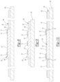
- FIG. 8 is a cross-sectional view, taken along line 8 - 8 of FIG. 6 , showing the dielectric material of the interconnect packaging structure;
- FIG. 9 is a cross-sectional view, taken along line 9 - 9 of FIG. 6 , showing the dielectric material of the interconnect packaging structure;
- FIG. 10 is a cross-sectional view, taken along line 10 - 10 of FIG. 7 , showing the transmission lines and the interconnects of the interconnect packaging structure deposited onto the dielectric material;
- FIG. 11 is a cross-sectional view, taken along line 11 - 11 of FIG. 7 , showing the transmission lines and the interconnects of the interconnect packaging structure deposited onto the dielectric material;
- FIG. 12 is a perspective view showing the interconnect packaging structure
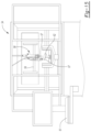
- FIG. 13 is a front elevational view showing a three-dimensional printer for printing the packaging structure
- FIG. 14 is a perspective view showing a nozzle of the printer and the interconnect packaging structure of FIG. 12 ;
- FIG. 15 is a front view elevational view showing a three-dimensional printer for printing the packaging structure.
- a primary automotive vehicle 10 (preferably an autonomous vehicle) is provided on a roadway with other automotive vehicles 14 .
- Primary vehicle 10 includes a collision detection system 16 that is capable of sensing and navigating objects, such as other secondary vehicles, posts, or people on or alongside the roadway, in proximity to primary vehicle 10 .
- Collision detection system 16 includes radar sensors 18 a , 18 b , 18 c , 18 d and 18 e , and a vehicle control module 20 .
- Radar sensors 18 a , 18 b , 18 c , 18 d and 18 e operate at various frequencies (including but not limited to 24 and 76 GHz systems) for detecting the secondary objects that are proximate to primary vehicle 10 .
- the field of view for radar sensors 18 a , 18 b , 18 c , 18 d and 18 e is designed to target the desired detection area to determine proximity of primary vehicle 10 to the objects.
- radar sensors 18 a , 18 b , 18 c , 18 d and 18 e are disclosed by way of example, other sensors that emit energy to obtain information on surrounding objects would benefit from the present disclosure.
- Radar sensors 18 a , 18 b , 18 c , 18 d and 18 e are mounted behind painted bumpers 22 or vehicle fascia panels 24 at various locations of primary vehicle 10 .
- radar sensors 18 a , 18 b , 18 c , 18 d and 18 e are disposed at a front right end 26 of primary vehicle 10 , a front left end 28 of primary vehicle 10 , a center area 30 of primary vehicle 10 , a back right end 32 of primary vehicle 10 and/or a back left end 34 of primary vehicle 10 , respectively.
- FIG. 1 and 2 radar sensors 18 a , 18 b , 18 c , 18 d and 18 e are disposed at a front right end 26 of primary vehicle 10 , a front left end 28 of primary vehicle 10 , a center area 30 of primary vehicle 10 , a back right end 32 of primary vehicle 10 and/or a back left end 34 of primary vehicle 10 , respectively.
- radar sensors 18 a and 18 b are mounted behind a crash beam 36 of primary vehicle 10 , which, in turn, is located proximate bumper 22 . It is also understood that primary vehicle 10 can include other radar sensors disposed at other locations thereof.
- Control module 20 including an electrical circuit with a microprocessor and memory, is disposed within vehicle 10 and is configured to communicate with radar sensors 18 a , 18 b , 18 c , 18 d and 18 e .
- control module 20 communicates with radar sensors 18 a , 18 b , 18 c , 18 d and 18 e such that radar sensors 18 a , 18 b , 18 c , 18 d and 18 e continuously transmit signals to or receive signals from the desired detection area.
- FIG. 3 shows a transmitter system 40 of radar sensors 18 a , 18 b , 18 c , 18 d and 18 e in communication with vehicle control module 20 and a transmitter antenna 42 .
- Transmitter system 40 includes amplifiers 44 a , 44 b , a mixer 46 and an oscillator 48 .
- Amplifier 44 a amplifies an RF signal generated by transmitter system 40 .
- Mixer 46 receives the amplified RF signal from amplifier 44 a and a signal from oscillator 48 and outputs a signal having a common intermediate frequency of the two, which, in turn, is amplified by amplifier 44 b and transmitted to the detection area (via transmitter antenna 42 ) to detect secondary objects 49 .
- Interconnect packaging structure 52 is manufactured using an Optomec Aersol Jet 5 ⁇ three-dimensional printer 54 , which is capable of additively printing or depositing features on a stacked layer-by-layer basis below 10 ⁇ m.
- the aerosolized materials are focused through a printer head 56 and a nozzle 57 .
- Nozzle 57 includes a sheath of nitrogen gas which prevents the printing or deposition material from coming into contact with the nozzle.
- Nozzle 57 operably linearly moves back and forth along a gantry 59 within printer 54 based on signals from a programmable computer controller 61 activating an actuator.
- a second dielectric material preferably polyimide
- a second dielectric material is deposited in gap 68 extending around and between the periphery of cavity 66 and integrated circuit 58 , thereby, forming a second substrate or body 70 .
- This is done by angling the table top 62 10 degrees and depositing the dielectric material, using the nozzle 57 , into gap 68 with no curing, thereby allowing the second dielectric material to fill gap 68 and form second substrate 70 .
- Top surface 72 of integrated circuit 58 sits slightly above gap 68 , therefore, filling gap 68 with the second dielectric material forms second substrate 70 having fillets or ramp surfaces 74 around integrated circuit 58 .
- Each ramp surface 74 extends from the periphery of cavity 66 to at least an edge of integrated circuit 58 .
- At least two ramp surfaces 74 extend onto top surface 72 of integrated circuit 58 and are adjacent to respective bonding pads 76 .
- transmission lines 78 are deposited onto surface 80 of first substrate 64 using printer 54 and extend from or near an end of first substrate 64 to a respective ramp surface 74 .
- Each transmission line 78 is preferably elongated and of a rectangular top view shape.
- Electrically conductive interconnects 82 preferably made of silver nanoparticle ink, are deposited onto respective ramp surfaces 74 and onto respective bonding pads 76 of integrated circuit 58 using printer 54 , thereby electrically connecting transmission lines 78 and bonding pads 76 on integrated circuit 58 .
- Bonding pads 76 are electrically coupled to ends of elongated conductors 81 that are fabricated on integrated circuit 58 and extend substantially parallel to each other.
- Interconnects 82 are deposited onto at least two ramp surfaces 74 that extend onto top surface 72 of integrated circuit 58 , adjacent to respective bonding pads 76 . In this way, interconnects 82 are prohibited from coming into contact with a metal seal ring (not shown) around integrated circuit 58 , thereby preventing an electrical short from interconnects 82 to the metal ring.
- Each interconnect 82 has a generally rectangular top view shape and more preferably a square shape.
- Transmission lines 78 and interconnects 82 have a thickness of 2 ⁇ m, which is deposited all at one time as oppose to in layers.
- the table top 62 is angled 10 degrees when the nozzle 57 is depositing interconnects 82 onto ramp surfaces 74 to ensure continuity therewith.
- interconnect packaging structure 52 is cured by heating, using heating element 67 (e.g., hot plate, heat pad, etc.) underneath table top 62 , in a nitrogen atmosphere.
- heating element 67 e.g., hot plate, heat pad, etc.
- interconnect packaging structure 52 is heated between 150 degrees Celsius and 200 degrees Celsius, preferably 180 degrees Celsius, for at least 15 minutes, more preferably 40 minutes.
- interconnect packaging structure 52 is heated between 200 degrees Celsius and 300 degrees Celsius, more preferably 280 degrees Celsius, for at least 15 minutes, more preferably 30 minutes.
- interconnect packaging structure 52 is heated between 300 degrees Celsius and 400 degrees Celsius, more preferably 300 degrees Celsius for at least 5 minutes, more preferably 10 minutes.
- integrated circuit 58 may be attached to a printed circuit board (PCB) as oppose to copper substrate 60 .
- PCB printed circuit board
- the height of integrated circuit 58 and the thickness of first substrate 64 may be of the same as opposed to being different.
- the curing can be done in an oven as oppose to using heating element 67 underneath table top 62 .
- transmission lines 78 may be deposited onto surface 80 of first substrate 64 and ramp surfaces 74 , thereby reducing the length of interconnects 82 . While certain materials have been disclosed it should be appreciated that alternate materials may be used although all of the present advantages may not be fully achieved. It is also noteworthy that any of the preceding features may be interchanged and intermixed with any of the others. Variations are not to be regarded as a departure from the present disclosure, and all such modifications are entitled to be included within the scope and spirit of the present invention.
Landscapes
- Engineering & Computer Science (AREA)
- Radar, Positioning & Navigation (AREA)
- Remote Sensing (AREA)
- Physics & Mathematics (AREA)
- Computer Networks & Wireless Communication (AREA)
- General Physics & Mathematics (AREA)
- Manufacturing & Machinery (AREA)
- Chemical & Material Sciences (AREA)
- Materials Engineering (AREA)
- Electromagnetism (AREA)
- Manufacturing Of Printed Wiring (AREA)
- Radar Systems Or Details Thereof (AREA)
Abstract
Description
Claims (18)
Priority Applications (1)
| Application Number | Priority Date | Filing Date | Title |
|---|---|---|---|
| US17/056,188 US12027477B2 (en) | 2018-05-18 | 2019-05-15 | Method of additively manufacturing an integrated circuit of an interconnect packaging structure |
Applications Claiming Priority (3)
| Application Number | Priority Date | Filing Date | Title |
|---|---|---|---|
| US201862673403P | 2018-05-18 | 2018-05-18 | |
| PCT/US2019/032501 WO2019222410A1 (en) | 2018-05-18 | 2019-05-15 | Manufactured interconnect packaging structure |
| US17/056,188 US12027477B2 (en) | 2018-05-18 | 2019-05-15 | Method of additively manufacturing an integrated circuit of an interconnect packaging structure |
Publications (2)
| Publication Number | Publication Date |
|---|---|
| US20210217712A1 US20210217712A1 (en) | 2021-07-15 |
| US12027477B2 true US12027477B2 (en) | 2024-07-02 |
Family
ID=68541013
Family Applications (1)
| Application Number | Title | Priority Date | Filing Date |
|---|---|---|---|
| US17/056,188 Active 2041-08-29 US12027477B2 (en) | 2018-05-18 | 2019-05-15 | Method of additively manufacturing an integrated circuit of an interconnect packaging structure |
Country Status (2)
| Country | Link |
|---|---|
| US (1) | US12027477B2 (en) |
| WO (1) | WO2019222410A1 (en) |
Families Citing this family (1)
| Publication number | Priority date | Publication date | Assignee | Title |
|---|---|---|---|---|
| CN117840703B (en) * | 2024-01-18 | 2026-04-17 | 芯体素(杭州)科技发展有限公司 | A method and apparatus for fabricating printing nozzles based on micropore filling |
Citations (19)
| Publication number | Priority date | Publication date | Assignee | Title |
|---|---|---|---|---|
| US6535116B1 (en) | 2000-08-17 | 2003-03-18 | Joe Huayue Zhou | Wireless vehicle monitoring system |
| US20060070554A1 (en) * | 2003-01-22 | 2006-04-06 | Braunreiter Carl J | Molded three-dimensional insulator |
| US20080191297A1 (en) * | 2007-02-12 | 2008-08-14 | Advanced Chip Engineering Technology Inc. | Wafer level image sensor package with die receiving cavity and method of the same |
| US20100140811A1 (en) | 2008-12-09 | 2010-06-10 | Vertical Circuits, Inc. | Semiconductor die interconnect formed by aerosol application of electrically conductive material |
| US8062976B2 (en) | 2009-07-28 | 2011-11-22 | Stmicroelectronics S.R.L. | Low cost method of fabrication of vertical interconnections combined to metal top electrodes |
| TW201218468A (en) * | 2010-10-26 | 2012-05-01 | Bridge Semiconductor Corp | Semiconductor chip assembly with bump/base heat spreader and cavity in bump |
| US20120161317A1 (en) | 2009-06-02 | 2012-06-28 | Hsio Technologies, Llc | Area array semiconductor device package interconnect structure with optional package-to-package or flexible circuit to package connection |
| US20130027240A1 (en) * | 2010-03-05 | 2013-01-31 | Sazzadur Chowdhury | Radar system and method of manufacturing same |
| US9305901B2 (en) | 2014-07-17 | 2016-04-05 | Seagate Technology Llc | Non-circular die package interconnect |
| US9508667B2 (en) | 2014-12-23 | 2016-11-29 | Intel Corporation | Formation of solder and copper interconnect structures and associated techniques and configurations |
| US20170129171A1 (en) * | 2015-11-09 | 2017-05-11 | U.S.A. As Represented By The Administrator Of The National Aeronautics And Space Administration | Devices and Methods for Additive Manufacturing Using Flexible Filaments |
| US20170251713A1 (en) * | 2016-03-07 | 2017-09-07 | Telamens, Inc. | 3d printer and method for printing an object using a curable liquid |
| US9799617B1 (en) * | 2016-07-27 | 2017-10-24 | Nxp Usa, Inc. | Methods for repackaging copper wire-bonded microelectronic die |
| US20180020683A1 (en) * | 2016-07-21 | 2018-01-25 | BeeHex, LLC | 3d-print system with integrated cnc robot and automatic self-cleaning mechanism |
| US20180036941A1 (en) * | 2015-04-28 | 2018-02-08 | Gold Array Technology (Beijing), Llc | Photo-curing 3d printer and 3d printing method |
| US20180068982A1 (en) * | 2014-10-15 | 2018-03-08 | Infineon Technologies Ag | Method of forming a chip assembly and chip assembly |
| US20180065302A1 (en) * | 2016-09-07 | 2018-03-08 | Canon Kabushiki Kaisha | Three-dimensional manufacturing apparatus, three-dimensional manufactured object producing method, and container for three-dimensional manufacturing apparatus |
| US20180104894A1 (en) * | 2016-05-13 | 2018-04-19 | Hewlett-Packard Development Company, L.P. | Three-dimensional printing |
| US20180207863A1 (en) * | 2017-01-20 | 2018-07-26 | Southern Methodist University | Methods and apparatus for additive manufacturing using extrusion and curing and spatially-modulated multiple materials |
-
2019
- 2019-05-15 US US17/056,188 patent/US12027477B2/en active Active
- 2019-05-15 WO PCT/US2019/032501 patent/WO2019222410A1/en not_active Ceased
Patent Citations (19)
| Publication number | Priority date | Publication date | Assignee | Title |
|---|---|---|---|---|
| US6535116B1 (en) | 2000-08-17 | 2003-03-18 | Joe Huayue Zhou | Wireless vehicle monitoring system |
| US20060070554A1 (en) * | 2003-01-22 | 2006-04-06 | Braunreiter Carl J | Molded three-dimensional insulator |
| US20080191297A1 (en) * | 2007-02-12 | 2008-08-14 | Advanced Chip Engineering Technology Inc. | Wafer level image sensor package with die receiving cavity and method of the same |
| US20100140811A1 (en) | 2008-12-09 | 2010-06-10 | Vertical Circuits, Inc. | Semiconductor die interconnect formed by aerosol application of electrically conductive material |
| US20120161317A1 (en) | 2009-06-02 | 2012-06-28 | Hsio Technologies, Llc | Area array semiconductor device package interconnect structure with optional package-to-package or flexible circuit to package connection |
| US8062976B2 (en) | 2009-07-28 | 2011-11-22 | Stmicroelectronics S.R.L. | Low cost method of fabrication of vertical interconnections combined to metal top electrodes |
| US20130027240A1 (en) * | 2010-03-05 | 2013-01-31 | Sazzadur Chowdhury | Radar system and method of manufacturing same |
| TW201218468A (en) * | 2010-10-26 | 2012-05-01 | Bridge Semiconductor Corp | Semiconductor chip assembly with bump/base heat spreader and cavity in bump |
| US9305901B2 (en) | 2014-07-17 | 2016-04-05 | Seagate Technology Llc | Non-circular die package interconnect |
| US20180068982A1 (en) * | 2014-10-15 | 2018-03-08 | Infineon Technologies Ag | Method of forming a chip assembly and chip assembly |
| US9508667B2 (en) | 2014-12-23 | 2016-11-29 | Intel Corporation | Formation of solder and copper interconnect structures and associated techniques and configurations |
| US20180036941A1 (en) * | 2015-04-28 | 2018-02-08 | Gold Array Technology (Beijing), Llc | Photo-curing 3d printer and 3d printing method |
| US20170129171A1 (en) * | 2015-11-09 | 2017-05-11 | U.S.A. As Represented By The Administrator Of The National Aeronautics And Space Administration | Devices and Methods for Additive Manufacturing Using Flexible Filaments |
| US20170251713A1 (en) * | 2016-03-07 | 2017-09-07 | Telamens, Inc. | 3d printer and method for printing an object using a curable liquid |
| US20180104894A1 (en) * | 2016-05-13 | 2018-04-19 | Hewlett-Packard Development Company, L.P. | Three-dimensional printing |
| US20180020683A1 (en) * | 2016-07-21 | 2018-01-25 | BeeHex, LLC | 3d-print system with integrated cnc robot and automatic self-cleaning mechanism |
| US9799617B1 (en) * | 2016-07-27 | 2017-10-24 | Nxp Usa, Inc. | Methods for repackaging copper wire-bonded microelectronic die |
| US20180065302A1 (en) * | 2016-09-07 | 2018-03-08 | Canon Kabushiki Kaisha | Three-dimensional manufacturing apparatus, three-dimensional manufactured object producing method, and container for three-dimensional manufacturing apparatus |
| US20180207863A1 (en) * | 2017-01-20 | 2018-07-26 | Southern Methodist University | Methods and apparatus for additive manufacturing using extrusion and curing and spatially-modulated multiple materials |
Non-Patent Citations (47)
Also Published As
| Publication number | Publication date |
|---|---|
| WO2019222410A1 (en) | 2019-11-21 |
| US20210217712A1 (en) | 2021-07-15 |
Similar Documents
| Publication | Publication Date | Title |
|---|---|---|
| JP7303815B2 (en) | Radar system for vehicle perimeter detection with synthetic resin antenna | |
| CN115117610B (en) | Single-layer air waveguide antenna integrated on circuit board | |
| CN113646890B (en) | Antenna on Package Integrated Circuit Device | |
| US10269726B2 (en) | Electronic circuit package | |
| US11799190B2 (en) | Antenna-on-package integrated circuit device | |
| US11791542B2 (en) | RF devices including conformal antennas and methods for manufacturing thereof | |
| CN114914672B (en) | Shaped waveguide antennas for radar assemblies | |
| US9245859B2 (en) | Wireless module | |
| CN104145335B (en) | Semiconductor module with integrated antenna structure | |
| TW201705834A (en) | Additive fabrication of single and multi-layer electronic circuits | |
| JP2010050628A (en) | Antenna apparatus | |
| WO2003040754A1 (en) | Mobile millimetric wave radar | |
| CN107196038A (en) | Signal device including substrate integrated waveguide | |
| CN116581520A (en) | Antenna arrangement, radar sensor arrangement and method for producing the antenna arrangement | |
| US12027477B2 (en) | Method of additively manufacturing an integrated circuit of an interconnect packaging structure | |
| US20080316126A1 (en) | Antenna System for a Radar Transceiver | |
| JP2007503587A (en) | Radar sensor for use in automobiles | |
| CN115296024B (en) | Multilayer air waveguide antenna with layer-to-layer connections | |
| CN118285019A (en) | Radar sensor and manufacturing method | |
| CN115685084A (en) | Radar sensor products | |
| JP7176872B2 (en) | Planar antenna device | |
| CN114649659B (en) | Sawtooth waveguide with grating lobes for suppression | |
| JP2023021066A (en) | multilayer printed circuit board | |
| CN114509725A (en) | Radar plate, preparation method thereof and millimeter wave radar | |
| US20230021656A1 (en) | Radar sensor having a waveguide structure |
Legal Events
| Date | Code | Title | Description |
|---|---|---|---|
| STPP | Information on status: patent application and granting procedure in general |
Free format text: APPLICATION DISPATCHED FROM PREEXAM, NOT YET DOCKETED |
|
| STPP | Information on status: patent application and granting procedure in general |
Free format text: DOCKETED NEW CASE - READY FOR EXAMINATION |
|
| STPP | Information on status: patent application and granting procedure in general |
Free format text: NON FINAL ACTION MAILED |
|
| STPP | Information on status: patent application and granting procedure in general |
Free format text: RESPONSE TO NON-FINAL OFFICE ACTION ENTERED AND FORWARDED TO EXAMINER |
|
| STPP | Information on status: patent application and granting procedure in general |
Free format text: NOTICE OF ALLOWANCE MAILED -- APPLICATION RECEIVED IN OFFICE OF PUBLICATIONS |
|
| ZAAB | Notice of allowance mailed |
Free format text: ORIGINAL CODE: MN/=. |
|
| STPP | Information on status: patent application and granting procedure in general |
Free format text: NOTICE OF ALLOWANCE MAILED -- APPLICATION RECEIVED IN OFFICE OF PUBLICATIONS |
|
| AS | Assignment |
Owner name: BOARD OF TRUSTEES OF MICHIGAN STATE UNIVERSITY, MICHIGAN Free format text: ASSIGNMENT OF ASSIGNORS INTEREST;ASSIGNORS:PAPAPOLYMEROU, IOANNIS;CHAHAL, PREMJEET;ALBRECHT, JOHN D.;AND OTHERS;SIGNING DATES FROM 20210226 TO 20211110;REEL/FRAME:067476/0682 |
|
| STPP | Information on status: patent application and granting procedure in general |
Free format text: PUBLICATIONS -- ISSUE FEE PAYMENT VERIFIED |
|
| STCF | Information on status: patent grant |
Free format text: PATENTED CASE |