US12025165B2 - Fastening device for fastening to a plate-like element - Google Patents
Fastening device for fastening to a plate-like element Download PDFInfo
- Publication number
- US12025165B2 US12025165B2 US17/422,284 US202017422284A US12025165B2 US 12025165 B2 US12025165 B2 US 12025165B2 US 202017422284 A US202017422284 A US 202017422284A US 12025165 B2 US12025165 B2 US 12025165B2
- Authority
- US
- United States
- Prior art keywords
- head
- fastening device
- blades
- core
- foot
- Prior art date
- Legal status (The legal status is an assumption and is not a legal conclusion. Google has not performed a legal analysis and makes no representation as to the accuracy of the status listed.)
- Active, expires
Links
Images


Classifications
-
- F—MECHANICAL ENGINEERING; LIGHTING; HEATING; WEAPONS; BLASTING
- F16—ENGINEERING ELEMENTS AND UNITS; GENERAL MEASURES FOR PRODUCING AND MAINTAINING EFFECTIVE FUNCTIONING OF MACHINES OR INSTALLATIONS; THERMAL INSULATION IN GENERAL
- F16B—DEVICES FOR FASTENING OR SECURING CONSTRUCTIONAL ELEMENTS OR MACHINE PARTS TOGETHER, e.g. NAILS, BOLTS, CIRCLIPS, CLAMPS, CLIPS OR WEDGES; JOINTS OR JOINTING
- F16B21/00—Means for preventing relative axial movement of a pin, spigot, shaft or the like and a member surrounding it; Stud-and-socket releasable fastenings
- F16B21/06—Releasable fastening devices with snap-action
- F16B21/08—Releasable fastening devices with snap-action in which the stud, pin, or spigot has a resilient part
- F16B21/086—Releasable fastening devices with snap-action in which the stud, pin, or spigot has a resilient part the shank of the stud, pin or spigot having elevations, ribs, fins or prongs intended for deformation or tilting predominantly in a direction perpendicular to the direction of insertion
-
- F—MECHANICAL ENGINEERING; LIGHTING; HEATING; WEAPONS; BLASTING
- F16—ENGINEERING ELEMENTS AND UNITS; GENERAL MEASURES FOR PRODUCING AND MAINTAINING EFFECTIVE FUNCTIONING OF MACHINES OR INSTALLATIONS; THERMAL INSULATION IN GENERAL
- F16B—DEVICES FOR FASTENING OR SECURING CONSTRUCTIONAL ELEMENTS OR MACHINE PARTS TOGETHER, e.g. NAILS, BOLTS, CIRCLIPS, CLAMPS, CLIPS OR WEDGES; JOINTS OR JOINTING
- F16B11/00—Connecting constructional elements or machine parts by sticking or pressing them together, e.g. cold pressure welding
- F16B11/006—Connecting constructional elements or machine parts by sticking or pressing them together, e.g. cold pressure welding by gluing
-
- F—MECHANICAL ENGINEERING; LIGHTING; HEATING; WEAPONS; BLASTING
- F16—ENGINEERING ELEMENTS AND UNITS; GENERAL MEASURES FOR PRODUCING AND MAINTAINING EFFECTIVE FUNCTIONING OF MACHINES OR INSTALLATIONS; THERMAL INSULATION IN GENERAL
- F16B—DEVICES FOR FASTENING OR SECURING CONSTRUCTIONAL ELEMENTS OR MACHINE PARTS TOGETHER, e.g. NAILS, BOLTS, CIRCLIPS, CLAMPS, CLIPS OR WEDGES; JOINTS OR JOINTING
- F16B5/00—Joining sheets or plates, e.g. panels, to one another or to strips or bars parallel to them
- F16B5/06—Joining sheets or plates, e.g. panels, to one another or to strips or bars parallel to them by means of clamps or clips
- F16B5/0607—Joining sheets or plates, e.g. panels, to one another or to strips or bars parallel to them by means of clamps or clips joining sheets or plates to each other
- F16B5/0621—Joining sheets or plates, e.g. panels, to one another or to strips or bars parallel to them by means of clamps or clips joining sheets or plates to each other in parallel relationship
- F16B5/0642—Joining sheets or plates, e.g. panels, to one another or to strips or bars parallel to them by means of clamps or clips joining sheets or plates to each other in parallel relationship the plates being arranged one on top of the other and in full close contact with each other
-
- F—MECHANICAL ENGINEERING; LIGHTING; HEATING; WEAPONS; BLASTING
- F16—ENGINEERING ELEMENTS AND UNITS; GENERAL MEASURES FOR PRODUCING AND MAINTAINING EFFECTIVE FUNCTIONING OF MACHINES OR INSTALLATIONS; THERMAL INSULATION IN GENERAL
- F16B—DEVICES FOR FASTENING OR SECURING CONSTRUCTIONAL ELEMENTS OR MACHINE PARTS TOGETHER, e.g. NAILS, BOLTS, CIRCLIPS, CLAMPS, CLIPS OR WEDGES; JOINTS OR JOINTING
- F16B33/00—Features common to bolt and nut
- F16B33/004—Sealing; Insulation
Definitions
- the invention relates to a fastening device for fastening same or elements to a preferably at least substantially plate-like element, in particular to a body panel of a vehicle.
- the invention furthermore relates to a method for producing such a fastening device.
- a “high” element for example a high shoulder
- Plate-like elements are also understood as meaning elements which have merely an at least substantially plate-like region (to which the fastening device is fastened). Apart from said substantially plate-like region, the plate-like elements can accordingly also be designed in some other way.
- the blades of the at least one group of blades which are elastic at least in regions are arranged next to one another in a manner sorted according to the height of their oblique shoulders.
- the oblique shoulders are arranged from high (in the vicinity of the head) to low (far away from the head).
- point of the oblique shoulder of a blade which is furthest away from the head i.e. the lowest point of the shoulder which is furthermore the furthermost outer point of the oblique shoulder
- the point (the highest point) is further away from the head (i.e. lower) than the point (the highest point), which is arranged closest to the head, of the oblique shoulder of an adjacent blade, the shoulder of which is further away from the head (i.e. lower).
- three groups of blades which are elastic at least in regions are formed, said blades preferably being of identical design, wherein the blades are preferably arranged distributed uniformly along the circumference of the core.
- each group of blades in each case has six blades, in each case three blades would therefore be arranged level with the six different heights (of the oblique shoulders).
- each of the blades has a connecting region which connects the respective shoulder to the core.
- the corresponding connecting region of at least one of the blades forms a stop region which is formed at least substantially orthogonally with respect to the plane with the axis of rotation of the core as a perpendicular.
- the stop region is therefore vertical or is a vertical plane. Alternatively thereto, however, it is also conceivable if the stop region is designed as a curved surface.
- the stop region is also formed orthogonally to the main direction of extent of the plate-like element and therefore parallel to the inner wall of the bore of the plate-like element to which the fastening device is fastened.
- the stop region can correspondingly form a stop for the plate-like element, and therefore the plate-like element is held securely.
- the connecting region on a side facing the head at least substantially does not have a slope with respect to the plane with the axis of rotation of the core as a perpendicular.
- the surface of a side of the connecting region towards the head is a horizontal surface.
- the latter furthermore simultaneously runs parallel to the plane with the axis of rotation of the core as a perpendicular.
- the connecting region on a side facing the head has a slope or a slope profile with respect to the plane with the axis of rotation of the core as a perpendicular.
- the side of the connecting region that faces the head is preferably always curved, i.e. formed with a slope or a slope profile, in order to permit simple mounting of the fastening device.
- the connecting regions are formed at different heights from one another along the axis of rotation of the core.
- the sides of the connecting regions of the blades that face the head can be at the same distance from the head or can be at different distances from one another from the head.
- the head has a plate-like basic region and an annular region which encircles the latter and protrudes in the direction of the foot.
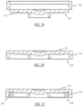
- the solution according to the invention consists in a method for producing a fastening device, which method has the following steps: injection moulding the head and the foot of the fastening device, wherein the annular region of the head points in a direction opposed to the foot; inserting the intermediate product consisting of the injection-moulded head and foot into a mould; closing the mould, wherein the annular region of the head is pressed downwards in the direction of the foot either during closing of the mould, or the annular region of the head is pressed downwards in the direction of the foot with the aid of a manipulator, in particular robot, specifically in each case in such a manner that, at least after the closing of the mould, the annular region protrudes from the plate-like basic region in the direction of the foot; and injecting the sealing material on a surface of the head that points in the direction of the foot.
- a geometry in which the annular region of the head points in a direction opposed to the foot can therefore be produced better by means of injection moulding.
- the advantages of the annular region that exist in conjunction with the sealing material can simultaneously also be used.
- FIG. 7 shows illustrations for the method for producing a fastening device according to the present invention.
- the fastening device 100 in FIG. 1 has three groups of blades 122 each having six blades 122 .
- Each group of blades 122 is constructed identically here, and therefore a total of six times three blades 122 having the oblique shoulder 123 at the same height are arranged on the core 121 of the foot 120 .
- the blade 122 having the oblique shoulder 123 arranged lowest (furthest away from the head 110 ) When the blade 122 having the oblique shoulder 123 arranged lowest (furthest away from the head 110 ) is overcome, a pull effect arises which pulls the fastening device 100 or the head 110 of the fastening device 100 in the direction of the plate-like element.
- the reason is in particular that the blades 122 are of flexible design and push outwards in the plate-like element or the bore of the plate-like element and because of the oblique shoulders 123 of the blades 122 that pull the fastening device 100 in the direction of the plate-like element.
- a stop region 125 which substantially has a vertical surface is formed on a region of the connecting region 124 that is adjacent to the oblique shoulder 123 . Said stop region 125 serves as a stop for the plate-like element or for the bore of the plate-like element.
- the inner side of the bore of a thick plate-like element lies against a blade 122 (or, in the case of three groups of blades 122 , against three blades 122 ) which has a stop region 125 which is at a distance from the head 110 .
- the blades 122 which are arranged on the right side in FIG. 2 A .
- the fastening device 100 assisted by the above-described pull effect is pushed or pulled into the bore of the plate-like element to an extent such that the inner wall of the bore of the plate-like element comes to stop against a stop region 125 of a blade 122 , said stop region being arranged close to the head 110 of the fastening device 100 .
- the feet 120 illustrated in FIGS. 2 A to 2 C furthermore share the feature that their connecting regions 124 have a substantially horizontal surface on an upper side (side in the direction of the head 110 ). That is to say that said horizontal upper side of the connecting regions 124 is arranged orthogonally to the stop region 125 of the corresponding blade 122 .
- the upper side of the connecting region 124 is arranged parallel to the plane with the axis of rotation 121 a of the core 121 as a perpendicular (upper side of connecting region 124 is parallel to a plane that is perpendicular to the axis of rotation 121 a of the core).
- the stop regions 125 of the blades 122 are arranged orthogonally with respect to said plane.
- the region arranged highest (smallest distance from the head 110 ) of the oblique shoulder 123 , i.e. the boundary region with respect to the stop region 125 , of a first blade 122 is arranged higher (i.e. closer to the head 110 ) than the lowest region of the oblique shoulder 123 , i.e. the outer region of the oblique shoulder 123 , of a blade 122 which has an oblique shoulder 123 formed higher (lying closer to the head 110 ).
- FIGS. 2 A to 2 C differ in that the blades 122 differ in design.
- the upper sides (side oriented in the direction of the head 110 ) of the connecting regions 124 are arranged at different distances from the head 110 corresponding to the oblique shoulders 123 and the stop regions 125 of the blades 122 .
- the lower sides of the blades 122 are formed substantially similarly and at the same height, and therefore the blades 122 become smaller from the blade placed closest to the head 110 to the blade 122 which is furthest away.
- the connecting regions 124 are all arranged at the same height, i.e. all at the same distance from the head 110 .
Landscapes
- Engineering & Computer Science (AREA)
- General Engineering & Computer Science (AREA)
- Mechanical Engineering (AREA)
- Insertion Pins And Rivets (AREA)
- Connection Of Plates (AREA)
Abstract
Description
Claims (15)
Applications Claiming Priority (3)
| Application Number | Priority Date | Filing Date | Title |
|---|---|---|---|
| DE102019100946.4 | 2019-01-15 | ||
| DE102019100946.4A DE102019100946A1 (en) | 2019-01-15 | 2019-01-15 | FASTENING DEVICE FOR FASTENING ON A PANEL-SHAPED ELEMENT |
| PCT/US2020/012680 WO2020150052A1 (en) | 2019-01-15 | 2020-01-08 | Fastening device for fastening to a plate-like element |
Publications (2)
| Publication Number | Publication Date |
|---|---|
| US20220120307A1 US20220120307A1 (en) | 2022-04-21 |
| US12025165B2 true US12025165B2 (en) | 2024-07-02 |
Family
ID=69469195
Family Applications (1)
| Application Number | Title | Priority Date | Filing Date |
|---|---|---|---|
| US17/422,284 Active 2041-02-07 US12025165B2 (en) | 2019-01-15 | 2020-01-08 | Fastening device for fastening to a plate-like element |
Country Status (4)
| Country | Link |
|---|---|
| US (1) | US12025165B2 (en) |
| CN (1) | CN113614393B (en) |
| DE (1) | DE102019100946A1 (en) |
| WO (1) | WO2020150052A1 (en) |
Families Citing this family (2)
| Publication number | Priority date | Publication date | Assignee | Title |
|---|---|---|---|---|
| GB2596149A (en) * | 2020-06-19 | 2021-12-22 | Bewi Energy As | Tubular end protector |
| DE102021100259B3 (en) | 2021-01-11 | 2022-04-21 | Bayerische Motoren Werke Aktiengesellschaft | Plug for a component, in particular a vehicle |
Citations (26)
| Publication number | Priority date | Publication date | Assignee | Title |
|---|---|---|---|---|
| US4334632A (en) * | 1980-03-03 | 1982-06-15 | Nifco Inc. | Stopper for opening |
| US5342139A (en) * | 1992-09-30 | 1994-08-30 | Bridgestone/Firestone, Inc. | Snap mounted attachment device |
| US5454479A (en) | 1992-12-14 | 1995-10-03 | Trw United Carr Gmbh & Co. Kg | Closure cover |
| CN1142019A (en) | 1995-02-08 | 1997-02-05 | Trw联合运载工具有限公司 | Fastening device made of plastic |
| DE202004007055U1 (en) | 2004-05-03 | 2004-07-01 | Böllhoff Verbindungstechnik GmbH | Plug element with ring flange, comprising three radial arranged elastic elements for being joined to sockets of various sizes |
| EP1688658A1 (en) | 2005-02-08 | 2006-08-09 | Fastpoint S.r.l. | Protective plug particularly for threaded holes, pipe ends, and the like |
| US20070108216A1 (en) * | 2003-07-24 | 2007-05-17 | Martin Kurth | Closure cap |
| WO2007099393A1 (en) | 2006-03-02 | 2007-09-07 | I.T.W. De France | A fastener provided with a snap-engagement foot for thrusting through a hole in a panel |
| US20070241256A1 (en) | 2006-04-13 | 2007-10-18 | Mario Stigler | Mounting clip |
| US20090265900A1 (en) | 2008-04-25 | 2009-10-29 | Piolazx, Inc. | Clip |
| FR2944569A1 (en) | 2009-04-20 | 2010-10-22 | Raymond A & Cie | RIB WING ATTACHMENT |
| USD638103S1 (en) * | 2007-04-02 | 2011-05-17 | Roll Larry D | Lift hole plug |
| US8162166B2 (en) * | 2006-11-24 | 2012-04-24 | Piolax Inc. | Hole plug |
| US8381943B2 (en) * | 2008-04-30 | 2013-02-26 | I.T.W. De France | Obturator |
| US8393058B2 (en) * | 2008-01-30 | 2013-03-12 | Piolax Inc. | Clip |
| FR3016937A1 (en) | 2014-01-24 | 2015-07-31 | Trw Automotive Electron & Comp | MOUNTING CLIP |
| CN105102830A (en) | 2013-03-27 | 2015-11-25 | 伊利诺斯工具制品有限公司 | System for fastening a component on a carrier component |
| EP2980422A1 (en) | 2014-07-29 | 2016-02-03 | Siemens Aktiengesellschaft | Fastener |
| US9309972B2 (en) * | 2011-11-16 | 2016-04-12 | Nifco Inc. | Hole plug |
| WO2016069125A1 (en) | 2014-10-31 | 2016-05-06 | Illinois Tool Works Inc. | Retaining device, in particular for removably connecting vehicle body parts |
| US9714055B2 (en) * | 2012-07-30 | 2017-07-25 | Nifco Inc. | Hole plug |
| US9850927B2 (en) * | 2015-08-04 | 2017-12-26 | The Boeing Company | Fastener installation in composite panels with fastener insert |
| US9963087B2 (en) * | 2012-06-01 | 2018-05-08 | Illinois Tool Works Inc. | Fastener comprising a snap-engagement foot to push through a hole in a panel and an engagement head configured to jut over said panel |
| US10640996B2 (en) * | 2015-08-31 | 2020-05-05 | Michael Hartman | Hole cover |
| US20200408236A1 (en) * | 2019-06-28 | 2020-12-31 | Illinois Tool Works Inc. | Assembly plug |
| US11255362B2 (en) * | 2018-06-01 | 2022-02-22 | Vibracoustic Usa, Inc. | Mount assembly with clip |
-
2019
- 2019-01-15 DE DE102019100946.4A patent/DE102019100946A1/en active Pending
-
2020
- 2020-01-08 WO PCT/US2020/012680 patent/WO2020150052A1/en not_active Ceased
- 2020-01-08 US US17/422,284 patent/US12025165B2/en active Active
- 2020-01-08 CN CN202080008566.2A patent/CN113614393B/en active Active
Patent Citations (29)
| Publication number | Priority date | Publication date | Assignee | Title |
|---|---|---|---|---|
| US4334632A (en) * | 1980-03-03 | 1982-06-15 | Nifco Inc. | Stopper for opening |
| US5342139A (en) * | 1992-09-30 | 1994-08-30 | Bridgestone/Firestone, Inc. | Snap mounted attachment device |
| US5454479A (en) | 1992-12-14 | 1995-10-03 | Trw United Carr Gmbh & Co. Kg | Closure cover |
| CN1142019A (en) | 1995-02-08 | 1997-02-05 | Trw联合运载工具有限公司 | Fastening device made of plastic |
| US5658110A (en) | 1995-02-08 | 1997-08-19 | Trw Inc. | Fastening element made of plastic |
| US20070108216A1 (en) * | 2003-07-24 | 2007-05-17 | Martin Kurth | Closure cap |
| DE202004007055U1 (en) | 2004-05-03 | 2004-07-01 | Böllhoff Verbindungstechnik GmbH | Plug element with ring flange, comprising three radial arranged elastic elements for being joined to sockets of various sizes |
| EP1688658A1 (en) | 2005-02-08 | 2006-08-09 | Fastpoint S.r.l. | Protective plug particularly for threaded holes, pipe ends, and the like |
| US7967539B2 (en) * | 2006-03-02 | 2011-06-28 | I.T.W. De France | Fastener provided with a snap-engagement foot for thrusting through a hole in a panel |
| US20090022567A1 (en) | 2006-03-02 | 2009-01-22 | I.T.W. De France | fastener provided with a snap-engagement foot for thrusting through a hole in a panel |
| WO2007099393A1 (en) | 2006-03-02 | 2007-09-07 | I.T.W. De France | A fastener provided with a snap-engagement foot for thrusting through a hole in a panel |
| US20070241256A1 (en) | 2006-04-13 | 2007-10-18 | Mario Stigler | Mounting clip |
| US8162166B2 (en) * | 2006-11-24 | 2012-04-24 | Piolax Inc. | Hole plug |
| USD638103S1 (en) * | 2007-04-02 | 2011-05-17 | Roll Larry D | Lift hole plug |
| US8393058B2 (en) * | 2008-01-30 | 2013-03-12 | Piolax Inc. | Clip |
| US20090265900A1 (en) | 2008-04-25 | 2009-10-29 | Piolazx, Inc. | Clip |
| US8381943B2 (en) * | 2008-04-30 | 2013-02-26 | I.T.W. De France | Obturator |
| FR2944569A1 (en) | 2009-04-20 | 2010-10-22 | Raymond A & Cie | RIB WING ATTACHMENT |
| US9309972B2 (en) * | 2011-11-16 | 2016-04-12 | Nifco Inc. | Hole plug |
| US9963087B2 (en) * | 2012-06-01 | 2018-05-08 | Illinois Tool Works Inc. | Fastener comprising a snap-engagement foot to push through a hole in a panel and an engagement head configured to jut over said panel |
| US9714055B2 (en) * | 2012-07-30 | 2017-07-25 | Nifco Inc. | Hole plug |
| CN105102830A (en) | 2013-03-27 | 2015-11-25 | 伊利诺斯工具制品有限公司 | System for fastening a component on a carrier component |
| FR3016937A1 (en) | 2014-01-24 | 2015-07-31 | Trw Automotive Electron & Comp | MOUNTING CLIP |
| EP2980422A1 (en) | 2014-07-29 | 2016-02-03 | Siemens Aktiengesellschaft | Fastener |
| WO2016069125A1 (en) | 2014-10-31 | 2016-05-06 | Illinois Tool Works Inc. | Retaining device, in particular for removably connecting vehicle body parts |
| US9850927B2 (en) * | 2015-08-04 | 2017-12-26 | The Boeing Company | Fastener installation in composite panels with fastener insert |
| US10640996B2 (en) * | 2015-08-31 | 2020-05-05 | Michael Hartman | Hole cover |
| US11255362B2 (en) * | 2018-06-01 | 2022-02-22 | Vibracoustic Usa, Inc. | Mount assembly with clip |
| US20200408236A1 (en) * | 2019-06-28 | 2020-12-31 | Illinois Tool Works Inc. | Assembly plug |
Non-Patent Citations (1)
| Title |
|---|
| PCT, International Search Report and Written Opinion, International Application No. PCT/US2020/012680; dated Apr. 14, 2020, 10 pages. |
Also Published As
| Publication number | Publication date |
|---|---|
| US20220120307A1 (en) | 2022-04-21 |
| CN113614393B (en) | 2023-05-16 |
| DE102019100946A1 (en) | 2020-07-16 |
| CN113614393A (en) | 2021-11-05 |
| WO2020150052A1 (en) | 2020-07-23 |
Similar Documents
| Publication | Publication Date | Title |
|---|---|---|
| US12025165B2 (en) | Fastening device for fastening to a plate-like element | |
| US4081879A (en) | Sealing member | |
| JP5833684B2 (en) | Bolt hole cap | |
| EP3061999B1 (en) | Hole plug | |
| US10569725B2 (en) | Grommet | |
| TR201907925T4 (en) | Injection mold component and methods for creating the butterfly glass, guide rail, flywheel, car door and vehicle. | |
| US20180281583A1 (en) | Single shot injection molded article | |
| US8672178B2 (en) | Hole plug assembly | |
| US9709171B2 (en) | Sealing reducing washer | |
| US20200355215A1 (en) | Friction fit electromagnetic effect protection cap system | |
| CN111959250B (en) | Vehicle outer waist seal assembly | |
| US20150060574A1 (en) | Overmolded component with a labyrinth seal | |
| US11608893B2 (en) | Light weight hole plug | |
| GB2360322A (en) | Improvements relating to fasteners | |
| CN208132833U (en) | A kind of installation tool of valve rod sealing member | |
| US11486517B2 (en) | Gland for a sealed feedthrough of an orifice of a partition | |
| JPH0999787A (en) | end cap | |
| WO2017205022A1 (en) | Fastener for fastening an element, which is to be fastened, to a carrier part of a vehicle with reduced corrosion risk | |
| JP2011052810A (en) | Resin clip | |
| CN204099371U (en) | The fixed structure of rivet | |
| US10404002B2 (en) | Insulating body for a plug connector | |
| JP2004179791A (en) | Antenna and method for manufacturing the same | |
| CN210265369U (en) | T-shaped single-side buckling structure | |
| JPH0544232Y2 (en) | ||
| CN215016236U (en) | Lid assembly and electric cooker |
Legal Events
| Date | Code | Title | Description |
|---|---|---|---|
| AS | Assignment |
Owner name: ILLINOIS TOOL WORKS INC., ILLINOIS Free format text: ASSIGNMENT OF ASSIGNORS INTEREST;ASSIGNORS:SCHERER, CHRISTIAN;WOLF, MATTHIAS;REEL/FRAME:056823/0713 Effective date: 20190312 |
|
| STPP | Information on status: patent application and granting procedure in general |
Free format text: APPLICATION DISPATCHED FROM PREEXAM, NOT YET DOCKETED |
|
| STPP | Information on status: patent application and granting procedure in general |
Free format text: DOCKETED NEW CASE - READY FOR EXAMINATION |
|
| STPP | Information on status: patent application and granting procedure in general |
Free format text: NOTICE OF ALLOWANCE MAILED -- APPLICATION RECEIVED IN OFFICE OF PUBLICATIONS |
|
| STPP | Information on status: patent application and granting procedure in general |
Free format text: AWAITING TC RESP., ISSUE FEE NOT PAID |
|
| STPP | Information on status: patent application and granting procedure in general |
Free format text: NOTICE OF ALLOWANCE MAILED -- APPLICATION RECEIVED IN OFFICE OF PUBLICATIONS |
|
| STPP | Information on status: patent application and granting procedure in general |
Free format text: DOCKETED NEW CASE - READY FOR EXAMINATION |
|
| STPP | Information on status: patent application and granting procedure in general |
Free format text: NOTICE OF ALLOWANCE MAILED -- APPLICATION RECEIVED IN OFFICE OF PUBLICATIONS |
|
| STPP | Information on status: patent application and granting procedure in general |
Free format text: PUBLICATIONS -- ISSUE FEE PAYMENT VERIFIED |
|
| STCF | Information on status: patent grant |
Free format text: PATENTED CASE |