US12019357B2 - Projector device with imaging lens - Google Patents
Projector device with imaging lens Download PDFInfo
- Publication number
- US12019357B2 US12019357B2 US17/751,850 US202217751850A US12019357B2 US 12019357 B2 US12019357 B2 US 12019357B2 US 202217751850 A US202217751850 A US 202217751850A US 12019357 B2 US12019357 B2 US 12019357B2
- Authority
- US
- United States
- Prior art keywords
- imaging unit
- housing section
- projector
- exterior chassis
- unit
- Prior art date
- Legal status (The legal status is an assumption and is not a legal conclusion. Google has not performed a legal analysis and makes no representation as to the accuracy of the status listed.)
- Active
Links
- 238000003384 imaging method Methods 0.000 title claims abstract description 130
- 230000003287 optical effect Effects 0.000 claims abstract description 26
- 230000007246 mechanism Effects 0.000 claims description 16
- 230000008878 coupling Effects 0.000 claims description 12
- 238000010168 coupling process Methods 0.000 claims description 12
- 238000005859 coupling reaction Methods 0.000 claims description 12
- 230000015572 biosynthetic process Effects 0.000 claims description 6
- 239000004973 liquid crystal related substance Substances 0.000 description 9
- 238000000034 method Methods 0.000 description 5
- 238000005516 engineering process Methods 0.000 description 2
- 230000010287 polarization Effects 0.000 description 2
- 238000006243 chemical reaction Methods 0.000 description 1
- 230000000295 complement effect Effects 0.000 description 1
- 238000010586 diagram Methods 0.000 description 1
- 239000000428 dust Substances 0.000 description 1
- 230000006870 function Effects 0.000 description 1
- 239000011521 glass Substances 0.000 description 1
- 229910052736 halogen Inorganic materials 0.000 description 1
- 150000002367 halogens Chemical class 0.000 description 1
- QSHDDOUJBYECFT-UHFFFAOYSA-N mercury Chemical compound [Hg] QSHDDOUJBYECFT-UHFFFAOYSA-N 0.000 description 1
- 229910052753 mercury Inorganic materials 0.000 description 1
- 229910044991 metal oxide Inorganic materials 0.000 description 1
- 150000004706 metal oxides Chemical class 0.000 description 1
- 239000011347 resin Substances 0.000 description 1
- 229920005989 resin Polymers 0.000 description 1
- 239000004065 semiconductor Substances 0.000 description 1
- 238000000926 separation method Methods 0.000 description 1
- 239000012780 transparent material Substances 0.000 description 1
Images


Classifications
-
- G—PHYSICS
- G03—PHOTOGRAPHY; CINEMATOGRAPHY; ANALOGOUS TECHNIQUES USING WAVES OTHER THAN OPTICAL WAVES; ELECTROGRAPHY; HOLOGRAPHY
- G03B—APPARATUS OR ARRANGEMENTS FOR TAKING PHOTOGRAPHS OR FOR PROJECTING OR VIEWING THEM; APPARATUS OR ARRANGEMENTS EMPLOYING ANALOGOUS TECHNIQUES USING WAVES OTHER THAN OPTICAL WAVES; ACCESSORIES THEREFOR
- G03B17/00—Details of cameras or camera bodies; Accessories therefor
- G03B17/48—Details of cameras or camera bodies; Accessories therefor adapted for combination with other photographic or optical apparatus
- G03B17/54—Details of cameras or camera bodies; Accessories therefor adapted for combination with other photographic or optical apparatus with projector
-
- G—PHYSICS
- G03—PHOTOGRAPHY; CINEMATOGRAPHY; ANALOGOUS TECHNIQUES USING WAVES OTHER THAN OPTICAL WAVES; ELECTROGRAPHY; HOLOGRAPHY
- G03B—APPARATUS OR ARRANGEMENTS FOR TAKING PHOTOGRAPHS OR FOR PROJECTING OR VIEWING THEM; APPARATUS OR ARRANGEMENTS EMPLOYING ANALOGOUS TECHNIQUES USING WAVES OTHER THAN OPTICAL WAVES; ACCESSORIES THEREFOR
- G03B21/00—Projectors or projection-type viewers; Accessories therefor
- G03B21/14—Details
- G03B21/145—Housing details, e.g. position adjustments thereof
-
- H—ELECTRICITY
- H04—ELECTRIC COMMUNICATION TECHNIQUE
- H04N—PICTORIAL COMMUNICATION, e.g. TELEVISION
- H04N9/00—Details of colour television systems
- H04N9/12—Picture reproducers
- H04N9/31—Projection devices for colour picture display, e.g. using electronic spatial light modulators [ESLM]
- H04N9/3102—Projection devices for colour picture display, e.g. using electronic spatial light modulators [ESLM] using two-dimensional electronic spatial light modulators
- H04N9/3105—Projection devices for colour picture display, e.g. using electronic spatial light modulators [ESLM] using two-dimensional electronic spatial light modulators for displaying all colours simultaneously, e.g. by using two or more electronic spatial light modulators
-
- H—ELECTRICITY
- H04—ELECTRIC COMMUNICATION TECHNIQUE
- H04N—PICTORIAL COMMUNICATION, e.g. TELEVISION
- H04N9/00—Details of colour television systems
- H04N9/12—Picture reproducers
- H04N9/31—Projection devices for colour picture display, e.g. using electronic spatial light modulators [ESLM]
- H04N9/3141—Constructional details thereof
-
- H—ELECTRICITY
- H04—ELECTRIC COMMUNICATION TECHNIQUE
- H04N—PICTORIAL COMMUNICATION, e.g. TELEVISION
- H04N9/00—Details of colour television systems
- H04N9/12—Picture reproducers
- H04N9/31—Projection devices for colour picture display, e.g. using electronic spatial light modulators [ESLM]
- H04N9/3179—Video signal processing therefor
-
- H—ELECTRICITY
- H04—ELECTRIC COMMUNICATION TECHNIQUE
- H04N—PICTORIAL COMMUNICATION, e.g. TELEVISION
- H04N9/00—Details of colour television systems
- H04N9/12—Picture reproducers
- H04N9/31—Projection devices for colour picture display, e.g. using electronic spatial light modulators [ESLM]
- H04N9/3191—Testing thereof
- H04N9/3194—Testing thereof including sensor feedback
Definitions
- the present disclosure relates to a projector.
- JP-A-2011-180804 (Document 1), there is disclosed a technology of attaching an imaging device for taking an image projected from a projector on as upper surface of a chassis of the projector using a hook-and-loop fastener in order to automatically perform distortion or focus adjustment of the projected image.
- a projector includes an exterior chassis provided with a housing section, a light source unit which is housed in the exterior chassis, and is configured to emit light, an image forming unit which is housed in the exterior chassis, and is configured to generate image light from the light, a projection optical unit which is attached to the exterior chassis, and is configured to project the image light, and an imaging unit which is configured to image the image light projected, and is detachably attached, wherein the imaging unit is housed in the housing section.
- a projector includes an exterior chassis, a housing section which is provided to the exterior chassis, and is configured to house an imaging unit which images image light projected, and is detachably attached, a light source unit which is housed in the exterior chassis, and is configured to emit light, an image forming unit which is housed in the exterior chassis, and is configured to generate the image light from the light, and a projection optical unit which is attached to the exterior chassis, and is configured to project the image light.
- FIG. 1 is perspective view showing a configuration of a projector.
- FIG. 2 is a diagram showing an internal configuration of the projector.
- FIG. 3 is a perspective view showing the configuration of the projector.
- FIG. 4 is a perspective view showing a configuration of a part of the projector.
- FIG. 5 is a front view showing a configuration of a housing section.
- FIG. 7 is a perspective view showing a configuration when combining an imaging unit and a fixation member with each other.
- FIG. 8 is a perspective view showing the configuration when combining the imaging unit and the fixation member with each other.
- FIG. 9 is a perspective view showing a configuration of a cover part.
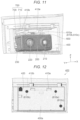
- FIG. 11 is a perspective view showing a configuration of an inside of the housing section.
- FIG. 12 is a front view showing the configuration of the inside of the housing section.
- FIG. 14 is a side view showing the configuration of the projector.
- FIG. 15 is a perspective view showing the configuration when combining the imaging unit and the fixation member with each other.
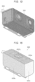
- FIG. 16 is a perspective view showing a configuration of the fixation member.
- FIG. 17 is a cross-sectional view showing a configuration of a housing section in a modified example.
- X direction A direction along the X axis is referred to as an “X direction”
- Y direction a direction along the B axis
- Z direction a direction along the Z axis
- an arrow direction is defined as a “+” direction while a direction opposite to the “+” direction is defined as a “ ⁇ ” direction.
- the +Z direction is also referred to as an “upper side” or “above” and the ⁇ Z direction is also referred to as a “lower side” or “below” in some cases, and a view from the +Z direction is also referred Co as a plan view or planar. Further, the description will be presented defining a surface at a “+” side in the Z direction as an upper surface, and a surface at a “ ⁇ ” side in the Z direction which is an opposite side thereto as a lower surface.
- the projector 1000 is provided with an exterior chassis 100 , a projection optical unit 1300 disposed at a first surface 100 a side of the exterior chassis 100 , an imaging unit 200 disposed at the ⁇ X direction side of the projection optical unit 1300 on the first surface 100 a , and a cover part 300 which covers the imaging unit 200 .
- the projector 1000 modulates image light projected from the projection optical unit 1300 in accordance with the image information to project an image on a projection target surface such as a screen in an enlarged manner.
- the imaging unit 200 is an imaging device for imaging the image light projected from the projection optical unit 1300 to automatically perform a distortion or focus adjustment of the image light.
- the imaging device is provided with an imaging element such as a CCD (Charge Coupled Device) or a CMOS (Complementary Metal Oxide Semiconductor).
- the exterior chassis 100 is provided with a housing section 400 which is recessed toward the inside of the exterior chassis 100 , which houses the imaging unit 200 , and which is located at a corner (at the ⁇ X direction side) in one end portion of the first surface 100 a .
- the exterior chassis 100 is provided with the cover part 300 for covering the imaging unit 200 housed inside the housing section 400 .
- the exterior chassis 100 has a plurality of cases such as an upper case constituting an upper part of the exterior chassis 100 , and a lower case constituting a lower part of the exterior chassis 100 . As described above, the exterior chassis 100 is provided with the housing section 400 for housing the imaging unit 200 .
- the light source unit 1100 is configured including a lamp unit 1101 formed of a white light source such as a ultrahigh pressure mercury lamp or a halogen lamp, an integrator lens 1102 , and a polarization conversion element 1103 .
- the image formation unit 1200 is a section for generating the image light from light emitted from the light source unit 1100 , and is provided with two dichroic mirrors 1104 , 1105 as a light separation element. Further, there are also provided three reflecting mirrors 1106 , 1107 , and 1108 , and five relay lenses 1201 , 1202 , 1203 , 1204 , and 1205 . Further, there are provided transmissive liquid crystal light valves 1210 , 1220 , and 1230 as three light modulators, and a cross dichroic prism 1206 as a light combining element.
- the red light (R) reflected by the dichroic mirror 1104 is reflected by the reflecting mirror 1106 , and then enters the liquid crystal light valve 1210 via the relay lens 1205 .
- the green light (G) reflected by the dichroic mirror 1105 enters the liquid crystal light valve 1220 via the relay lens 1204 .
- the blue light (B) transmitted through the dichroic mirror 1105 enters the liquid crystal light valve 1230 via a light guide system constituted by the three relay lenses 1201 , 1202 , and 1203 and the two reflecting mirrors 1107 , 1108 .
- the liquid crystal light valves 1210 , 1220 , and 1230 are arranged so as to be opposed respectively to planes of incidence of the colored light beams of the cross dichroic prism 1206 .
- the colored light beams having respectively entered the liquid crystal light valves 1210 , 1220 , and 1230 are modulated based on video information (a video signal), and are then emitted toward the cross dichroic prism 1206 .
- This prism is formed by bonding four rectangular prisms to each other, and is provided with a dielectric multilayer film for reflecting the red light and a dielectric multilayer film for reflecting the blue light formed on the inside surfaces so as to form a crisscross.
- the three colored light beams are combined with each other by these dielectric multilayer films, and thus the light expressing a color image is synthesized.
- the projection optical unit 1300 is arranged in a replaceable manner, and is provided with a projection lens 1207 which partially projects from the exterior chassis 100 .
- the projection optical unit 1300 is attached to the exterior chassis 100 via a lens holder and a lens shifting mechanism not shown.
- the image light thus synthesized is projected on a screen 1400 by the projection lens 1207 , and thus the image is displayed in an enlarged manner.
- liquid crystal light valve 1210 a pair of polarization elements respectively arranged at the incident side and the exit side of the colored light of a liquid crystal device not shown in a cross-Nicol arrangement are arranged at a distance. The same applies to the other liquid crystal light valves 1220 , 1230 .
- the controller 500 is provided with electronic components such as a CPU (Central Processing Unit), a ROM (Read Only Memory), a RAM (Random Access Memory), and so on.
- the controller 500 performs control of an operation of each section of the projector 1000 such as control related to the projection of the image.
- the controller 500 controls the image based on the image information obtained by the imaging unit 200 .
- the projector 1000 there is prepared the projector 1000 .
- the cover part 300 On the first surface 100 a of the exterior chassis 100 of the projector 1000 , there is mounted the cover part 300 .
- the cover part 300 is detached from the exterior chassis 100 . It is possible for the cover part 300 to be fixed to the exterior chassis 100 with a screw, or can also be fitted therein along a guide groove.
- the housing section 400 for housing the imaging unit 200 appears on the first surface 100 a of the exterior chassis 100 as shown in FIG. 4 and FIG. 5 . It should be noted that in the housing section 400 , there is disposed a fixation member 600 for attaching the imaging unit 200 .
- the fixation member 600 is detached from the housing section 400 .
- the fixation member 600 is fixed to, for example, a side surface 400 a at the +Y direction side in the housing section 400 with such three screws 610 a , 610 b , and 610 c as shown in FIG. 8 .
- By fixing the fixation member 600 at least with the two screws 610 a , 610 b in the X direction and the one screw 610 c in the Z direction it is possible to prevent the fixation member 600 from rotating in a plane direction of the side surface 400 a . It should be noted that it is also possible to arrange that the fixation member 600 is fixed with the two screws 610 a , 610 b in the X direction.
- the imaging unit 200 is attached to the fixation member 600 .
- the fixation member 600 and the imaging unit 200 are fixed to each other with a fixation screw 620 .
- the positioning mechanisms are each arranged at both sides across the fixation screw 620 .
- the position in the height direction (the Z direction) in the imaging unit 200 is decided.
- the imaging unit 200 fixed to the fixation member 600 is housed in the housing section 400 .
- a second cover 320 in a portion corresponding to an opening part 311 is detached from a first cover 310 as shown in FIG. 9 .
- the imaging unit 200 in the present embodiment is provided with the two imaging lenses 210 , 220 through which the image light is transmitted as shown in FIG. 11 , but this is not a limitation, and it is possible for the imaging unit 200 to be formed of a single imaging lens.
- the second cover 320 is provided to the first cover 310 so as to be able to be opened and closed.
- the second cover 320 is fixed at an opposite side to the side at which the imaging unit 200 is attached in the fixation member 600 as shown in FIG. 10 so as to prevent the second cover 320 having been detached from being lost.
- the fixation method for example, protrusions 321 a , 321 b of the second cover 320 are fitted into opening holes 640 a , 640 b provided to the fixation member 600 , and further, a resilient portion 322 of the second cover 320 is pressed into, and fixed to a fixation part 650 shaped like a protrusion provided to the fixation member 600 .
- the imaging unit 200 is housed in the housing section 400 .
- a cable 700 which is electrically coupled to an inside of the projector 1000 via an opening hole 420 of the housing section 400 , and is pulled out into the housing section 400 is further pulled out to an outside of the housing section 400 .
- the cable 700 has a wiring part 710 and a connector 720 attached to a tip of the wiring part 710 .
- the length of the cable 700 housed inside the housing section 400 is longer than the depth (in the +Y direction) of the housing section 400 . Therefore, it is possible to pull out the cable 700 from the inside of the housing section 400 to the outside of the housing section 400 .
- the connector 720 is inserted into a coupling part 230 of the imaging unit 200 to electrically couple the cable 700 and the imaging unit 200 to each other.
- the imaging unit 200 is housed in the housing section 400 .
- the imaging unit 200 is fixed by attaching the fixation member 600 to the side surface 400 a of the housing section 400 using the three screws 610 a , 610 b , and 610 c.
- the cable 700 pulled out to the outside of the housing section 400 is housed inside the housing section 400 .
- a superfluous portion of the cable 700 is folded to be inserted into a gap between support parts 410 a , 410 b arranged on the side surface 400 a of the housing section 400 and the upper surface of the housing section 400 to thereby support the cable 700 .
- FIG. 13 Due to the process described hereinabove, as shown in FIG. 13 , there is created the state in which the imaging unit 200 is housed in the housing section 400 . Subsequently, by fitting the first cover 310 shown in FIG. 9 into the exterior chassis 100 so as to cover the housing section 400 , it is possible to provide the projector 1000 of a built-in camera type as shown in FIG. 1 .
- the controller 500 performs, for example, the distortion or focus adjustment of the image light based on the image light obtained by the imaging unit 200 .
- an amount B of the projection of the imaging unit 200 from the first surface 100 a is sufficient for an amount B of the projection of the imaging unit 200 from the first surface 100 a to be made smaller than at least an amount A of the projection of the projection optical unit 1300 from the first surface 100 a as shown in FIG. 14 .
- FIG. 15 shows a state in which the imaging unit 200 is attached to the fixation member 600 .
- FIG. 16 shows a state in which the imaging unit 200 is detached from the fixation member 600 in the state shown in FIG. 15 .
- fixation member 600 since the three wall parts 600 a , 600 b , and 600 c are provided to the fixation member 600 , it is possible to make it easier to guide the imaging unit 200 in the positioning between the imaging unit 200 and the fixation member 600 . Further, since the fixation member 600 is constituted by the three wall parts 600 a , 600 b , and 600 c , it is possible to increase the strength of the fixation member 600 .
- the projector 1000 is provided with the exterior chassis 100 provided with the housing section 400 , the light source unit 1100 which is housed in the exterior chassis 100 , and emits the light, the image forming unit 1200 which is housed in the exterior chassis 100 , and generates the image light from the light, the projection optical unit 1300 which is attached to the exterior chassis 100 , and projects the image light, and the imaging unit 200 which is detachably attached, and images the image light projected, wherein the imaging unit 200 is housed in the housing section 400 .
- the imaging unit 200 since the imaging unit 200 is housed in the housing section 400 to be housed in the exterior chassis 100 , it becomes possible to reduce the projection from the exterior chassis 100 as much as the size of the housing section 400 . Therefore, even when attaching the imaging unit 200 , it is possible to prevent the projector 1000 from growing in size.
- the projector 1000 is provided with the exterior chassis 100 , the housing section 400 which is provided to the exterior chassis 100 , and in which the imaging unit 200 which is detachably attached, and images the image light projected is housed, the light source unit 1100 which is housed in the exterior chassis 100 , and emits the light, the image forming unit 1200 which is housed in the exterior chassis 100 , and generates the image light from the light, the projection optical unit 1300 which is attached to the exterior chassis 100 , and projects the image light.
- the housing section 400 in which the imaging unit 200 detachably attached is housed is provided to the exterior chassis 100 , it becomes possible to reduce the projection from the exterior chassis 100 as much as the size of the housing section 400 . Therefore, even when attaching the imaging unit 200 , it is possible to prevent the projector 1000 from growing in size.
- the fixation member 600 which is housed in the housing section 400 , and fixes the imaging unit 200 , and to provide the fixation member 600 and the imaging unit 200 with the positioning mechanisms (the opening holes 630 a , 630 b , and the protrusions 200 a , 200 b ) for determining the relative position therebetween.
- the positioning mechanisms the opening holes 630 a , 630 b , and the protrusions 200 a , 200 b
- the exterior chassis 100 has the first surface 100 a as a surface on which the projection optical unit 1300 is disposed, and the amount B of the projection of the imaging unit 200 from the first surface 100 a is smaller than the amount A of the projection of the projection optical unit 1300 from the first surface 100 a . According to this configuration, even when attaching the imaging unit 200 to the projector 1000 , it is possible to reduce the amount of the projection toward the first surface 100 a of the projector 1000 (the projection side in the projector 1000 ), and it is possible to prevent the projector 1000 from growing in size.
- the exterior chassis 100 it is preferable for the exterior chassis 100 to have the first surface 100 a as the surface on which the projection optical unit 1300 is disposed, and it is preferable for the imaging unit 200 not to project from the first surface 100 a . According to this configuration, even when attaching the imaging unit 200 to the projector 1000 , since the imaging unit 200 does not project toward the first surface 100 a of the projector 1000 (the projection side in the projector 1000 ), it is possible to prevent the projector 1000 from growing in size. In addition, since the imaging unit 200 does not project from the exterior chassis 100 , it is possible to improve the portability and the exterior appearance of the projector 1000 .
- the exterior chassis 100 it is preferable for the exterior chassis 100 to have the cover part 300 which covers the housing section 400 , and is capable of opening and closing. According to this configuration, since there is provided the cover part 300 for covering the housing section 400 , it is possible to protect the imaging unit 200 from an impact and dust even when installing the imaging unit 200 in the housing section 400 . Further, since the housing section 400 is covered with the cover part 300 , it is possible to improve the exterior appearance of the projector 1000 .
- the imaging unit 200 it is preferable for the imaging unit 200 to be provided with the imaging lenses 210 , 220 through which the image light is transmitted, and it is preferable for the cover part 300 to have the opening part 311 capable of opening and closing at the position corresponding to the imaging lenses 210 , 220 .
- the opening part 311 since there is disposed the opening part 311 at the position corresponding to the imaging lenses 210 , 220 , it is possible to protect the imaging unit 200 , and at the same time, to image the image light even when attaching the cover part 300 to the exterior chassis 100 .
- the fixation member 600 it is preferable for the fixation member 600 to be provided with the first wall part 600 a provided with the positioning mechanism, the second wall part 600 b disposed in a direction crossing the first wall part 600 a , and the third wall part 600 c disposed in a direction crossing the first all part 600 a and the second wall part 600 b .
- the fixation member 600 since the fixation member 600 is provided with the three wall parts 600 a , 600 b , and 600 c , it is possible to make it easier to guide the imaging unit 200 in the positioning between the imaging unit 200 and the fixation member 600 .
- the fixation member 600 is constituted by the three wall parts 600 a , 600 b , and 600 c , it is possible to increase the strength of the fixation member 600 .
- the housing section 400 it is preferable for the housing section 400 to be provided with the cable 700 having the connector 720 to electrically be coupled to the imaging unit 200 , and the support parts 410 a , 410 b for supporting the cable 700 , and it is preferable for the cable 700 extending in the housing section 400 to be longer in length than the depth of the housing section 400 .
- the cable 700 since the cable 700 is longer in length than the depth of the housing section 400 , when attaching or detaching the imaging unit 200 to or from the fixation member 600 , it is possible to perform the operation outside the exterior chassis 100 . Further, by folding the cable 700 to be fixed to the support parts 410 a , 410 b , it is possible to compactly house the cable 700 long in length.
- the configuration in which only the imaging unit 200 is housed in the housing section 400 is not a limitation, and it is possible to adopt, for example, a configuration shown in FIG. 17 .
- a housing section 400 A in the modified example a housing region is expanded downward from the region where the imaging unit 200 is disposed. In the region thus expanded, it is possible to house a coupling target device other than the imaging unit 200 .
- holding mechanisms 430 a , 430 b for holding the coupling target device in the housing section 400 A.
- the holding mechanisms 430 a , 430 b there can be cited a resilient member such as a spring.
- the coupling target device is made capable of wirelessly communicating with the projector 1000 .
- a device such as a wireless LAN or a body sensor is housed in the region thus expanded.
- the housing section 400 A it is preferable for the housing section 400 A to be provided with the holding mechanisms 430 a , 430 b for holding the coupling target device to electrically be coupled to the projector 1000 , and it is preferable for the housing section 400 A to house the imaging unit 200 and the coupling target device. According to this configuration, since it is possible to house the two or more devices in the housing section 400 A such as the imaging unit 200 and the coupling target device, it is possible to prevent the growth in size even when the plurality of devices and the projector 1000 are coupled to each other.
- the imaging unit 200 is fixed to the side surface 400 a of the housing section 400 with the screws 610 a , 610 b , and 610 c via the fixation member 600 , but this is not a limitation, and it is possible to adopt a sliding method, biasing with a biasing member, or the like.
- the position of the coupling part 230 of the imaging unit 200 can be arranged at an opposite side to the position in the embodiment described above. Further, it is also possible to arrange that the position of the third wall part 600 c constituting the fixation member 600 is also arranged at an opposite side in accordance with the position of the coupling part 230 . Further, it is possible to arrange that the position of the coupling part 230 is arranged on upper and lower surfaces of the imaging unit 200 .
- the imaging unit 200 is not limited to the arrangement of being arranged at the front side (the first surface 100 a side) of the exterior chassis 100 , and it is sufficient for the imaging unit 200 to be able to image the image light projected, and when, for example, the imaging unit 200 is arranged at a position other than the front side, it is possible to arrange to perform imaging in a folded manner, or when being applied to a single focus type projector, it is possible to arrange the imaging unit 200 on an upper surface or a lower surface of the exterior chassis.
- the positioning mechanisms for determining the positions of the fixation member 600 and the imaging unit 200 are not limited to the configuration of the embodiment described above, and it is possible to arrange that, for example, the opening hole is formed at the imaging unit 200 side, and the protrusion is provided to the fixation member 600 .
- the screw 620 for attaching the imaging unit 200 to the fixation member 600 is not limited to just one type, and it is possible to form a screw of, for example, a camera standard, or it is possible to arrange to form a versatile screw. Further, the same applies to the screw for attaching the fixation member 600 to the housing section 400 .
- cover part 300 is not limited to one formed of a general resin having a non-light transmissive property, and can also be formed using a transparent material such as glass.
Landscapes
- Physics & Mathematics (AREA)
- General Physics & Mathematics (AREA)
- Engineering & Computer Science (AREA)
- Multimedia (AREA)
- Signal Processing (AREA)
- Projection Apparatus (AREA)
Abstract
Description
Claims (12)
Applications Claiming Priority (2)
| Application Number | Priority Date | Filing Date | Title |
|---|---|---|---|
| JP2021086725A JP2022179913A (en) | 2021-05-24 | 2021-05-24 | projector |
| JP2021-086725 | 2021-05-24 |
Publications (2)
| Publication Number | Publication Date |
|---|---|
| US20220373868A1 US20220373868A1 (en) | 2022-11-24 |
| US12019357B2 true US12019357B2 (en) | 2024-06-25 |
Family
ID=84103584
Family Applications (1)
| Application Number | Title | Priority Date | Filing Date |
|---|---|---|---|
| US17/751,850 Active US12019357B2 (en) | 2021-05-24 | 2022-05-24 | Projector device with imaging lens |
Country Status (2)
| Country | Link |
|---|---|
| US (1) | US12019357B2 (en) |
| JP (2) | JP2022179913A (en) |
Citations (12)
| Publication number | Priority date | Publication date | Assignee | Title |
|---|---|---|---|---|
| US20100002123A1 (en) * | 2005-02-08 | 2010-01-07 | Nikon Corporation | Digital camera with projector and digital camera system |
| US20110187943A1 (en) * | 2010-02-03 | 2011-08-04 | International Business Machines Corporation | Information Technology System With Micro Projector Display |
| JP2011180804A (en) | 2010-03-01 | 2011-09-15 | Seiko Epson Corp | Unit and system for position detection |
| US20130265551A1 (en) * | 2012-04-10 | 2013-10-10 | Seiko Epson Corporation | Projection system, support, and image display method |
| US20150049309A1 (en) * | 2013-08-14 | 2015-02-19 | Shinichi SUMIYOSHI | Image projection apparatus and presentation system |
| US20150138513A1 (en) * | 2013-11-20 | 2015-05-21 | Seiko Epson Corporation | Projector, and method of controlling projector |
| US20150323859A1 (en) * | 2014-05-08 | 2015-11-12 | Fujitsu Limited | Projection device |
| US20160259402A1 (en) * | 2015-03-02 | 2016-09-08 | Koji Masuda | Contact detection apparatus, projector apparatus, electronic board apparatus, digital signage apparatus, projector system, and contact detection method |
| US20170208307A1 (en) * | 2016-01-20 | 2017-07-20 | Seiko Epson Corporation | Projector |
| US20210165309A1 (en) * | 2019-11-29 | 2021-06-03 | Seiko Epson Corporation | Projector, projection optical device, and method of controlling projector |
| US20210235050A1 (en) * | 2020-01-24 | 2021-07-29 | Seiko Epson Corporation | Method for controlling projector, projector, and display system |
| US20210356849A1 (en) * | 2020-05-12 | 2021-11-18 | Ditto Products Llc | Image projecting systems and methods |
Family Cites Families (15)
| Publication number | Priority date | Publication date | Assignee | Title |
|---|---|---|---|---|
| JP3742006B2 (en) * | 2001-12-26 | 2006-02-01 | Necパーソナルプロダクツ株式会社 | Electronic unit mounting structure |
| JP2003339112A (en) * | 2002-05-22 | 2003-11-28 | Sony Corp | Device and method for holding linear member, and electronic device |
| JP2004320830A (en) * | 2003-04-11 | 2004-11-11 | Fujikura Ltd | Harness fixing structure |
| JP3748076B2 (en) * | 2003-10-22 | 2006-02-22 | 船井電機株式会社 | LCD televisions, panel display televisions |
| JP2005195879A (en) * | 2004-01-07 | 2005-07-21 | Olympus Corp | Projector |
| JP2005257766A (en) * | 2004-03-09 | 2005-09-22 | Casio Comput Co Ltd | Projection apparatus, projection method, and program |
| TW200919069A (en) * | 2007-10-25 | 2009-05-01 | Asia Optical Co Inc | Optical engine for improving electromagnetic interference |
| JP2010080032A (en) * | 2008-09-29 | 2010-04-08 | Teac Corp | Hard disk unit and recording/reproducing device including the same |
| JP2010220069A (en) * | 2009-03-18 | 2010-09-30 | Nikon Corp | Electronics |
| JP2012018292A (en) * | 2010-07-08 | 2012-01-26 | Seiko Epson Corp | Manufacturing method of projection device, manufacturing apparatus of projection device, and projection device |
| JP2013122491A (en) * | 2011-12-09 | 2013-06-20 | Sanyo Electric Co Ltd | Projection type video display device |
| JP6646964B2 (en) * | 2015-07-29 | 2020-02-14 | キヤノン株式会社 | Projection display device and projection display system |
| JP6878816B2 (en) * | 2016-01-20 | 2021-06-02 | セイコーエプソン株式会社 | projector |
| JP7147617B2 (en) * | 2019-02-19 | 2022-10-05 | セイコーエプソン株式会社 | Projector and projector control method |
| CN114424118A (en) * | 2019-07-09 | 2022-04-29 | 麦克赛尔株式会社 | Projection type image display device |
-
2021
- 2021-05-24 JP JP2021086725A patent/JP2022179913A/en active Pending
-
2022
- 2022-05-24 US US17/751,850 patent/US12019357B2/en active Active
-
2025
- 2025-05-07 JP JP2025077174A patent/JP2025109751A/en active Pending
Patent Citations (12)
| Publication number | Priority date | Publication date | Assignee | Title |
|---|---|---|---|---|
| US20100002123A1 (en) * | 2005-02-08 | 2010-01-07 | Nikon Corporation | Digital camera with projector and digital camera system |
| US20110187943A1 (en) * | 2010-02-03 | 2011-08-04 | International Business Machines Corporation | Information Technology System With Micro Projector Display |
| JP2011180804A (en) | 2010-03-01 | 2011-09-15 | Seiko Epson Corp | Unit and system for position detection |
| US20130265551A1 (en) * | 2012-04-10 | 2013-10-10 | Seiko Epson Corporation | Projection system, support, and image display method |
| US20150049309A1 (en) * | 2013-08-14 | 2015-02-19 | Shinichi SUMIYOSHI | Image projection apparatus and presentation system |
| US20150138513A1 (en) * | 2013-11-20 | 2015-05-21 | Seiko Epson Corporation | Projector, and method of controlling projector |
| US20150323859A1 (en) * | 2014-05-08 | 2015-11-12 | Fujitsu Limited | Projection device |
| US20160259402A1 (en) * | 2015-03-02 | 2016-09-08 | Koji Masuda | Contact detection apparatus, projector apparatus, electronic board apparatus, digital signage apparatus, projector system, and contact detection method |
| US20170208307A1 (en) * | 2016-01-20 | 2017-07-20 | Seiko Epson Corporation | Projector |
| US20210165309A1 (en) * | 2019-11-29 | 2021-06-03 | Seiko Epson Corporation | Projector, projection optical device, and method of controlling projector |
| US20210235050A1 (en) * | 2020-01-24 | 2021-07-29 | Seiko Epson Corporation | Method for controlling projector, projector, and display system |
| US20210356849A1 (en) * | 2020-05-12 | 2021-11-18 | Ditto Products Llc | Image projecting systems and methods |
Also Published As
| Publication number | Publication date |
|---|---|
| US20220373868A1 (en) | 2022-11-24 |
| JP2025109751A (en) | 2025-07-25 |
| JP2022179913A (en) | 2022-12-06 |
Similar Documents
| Publication | Publication Date | Title |
|---|---|---|
| US12216391B2 (en) | Projector with rotatable projection lens | |
| CN101614945B (en) | Optical device and projector | |
| JP4433054B2 (en) | projector | |
| US20090086172A1 (en) | Optical Device and Projector | |
| CN107430257B (en) | Projection optical device and projector | |
| JP2013038626A (en) | Imaging apparatus and projector | |
| JP2004205716A (en) | Optical component housing, optical device, and projector | |
| JP4525757B2 (en) | projector | |
| US12019357B2 (en) | Projector device with imaging lens | |
| JP4127047B2 (en) | Projector housing and projector provided with the housing | |
| JP5245936B2 (en) | projector | |
| JP7533143B2 (en) | Projection Optical Device | |
| US6869186B2 (en) | Optical device and projector | |
| JP2004138913A (en) | Optical component housing, optical unit and projector | |
| JP2009171179A (en) | Electronics | |
| JP2009025771A (en) | Electronics | |
| JP2024119133A (en) | Projection display device | |
| JP5347439B2 (en) | projector | |
| JP2024084268A (en) | Projection device and projector | |
| JP2009086200A (en) | projector | |
| JP2018017848A (en) | projector | |
| JP2012173377A (en) | Projector and image display system | |
| JP2007240602A (en) | Optical apparatus and projector |
Legal Events
| Date | Code | Title | Description |
|---|---|---|---|
| AS | Assignment |
Owner name: SEIKO EPSON CORPORATION, JAPAN Free format text: ASSIGNMENT OF ASSIGNORS INTEREST;ASSIGNOR:YAMANO, DAIGO;REEL/FRAME:059996/0022 Effective date: 20220407 |
|
| STPP | Information on status: patent application and granting procedure in general |
Free format text: DOCKETED NEW CASE - READY FOR EXAMINATION |
|
| STPP | Information on status: patent application and granting procedure in general |
Free format text: NON FINAL ACTION MAILED |
|
| STPP | Information on status: patent application and granting procedure in general |
Free format text: RESPONSE TO NON-FINAL OFFICE ACTION ENTERED AND FORWARDED TO EXAMINER |
|
| STPP | Information on status: patent application and granting procedure in general |
Free format text: FINAL REJECTION MAILED |
|
| STPP | Information on status: patent application and granting procedure in general |
Free format text: DOCKETED NEW CASE - READY FOR EXAMINATION |
|
| STPP | Information on status: patent application and granting procedure in general |
Free format text: NOTICE OF ALLOWANCE MAILED -- APPLICATION RECEIVED IN OFFICE OF PUBLICATIONS |
|
| STPP | Information on status: patent application and granting procedure in general |
Free format text: PUBLICATIONS -- ISSUE FEE PAYMENT VERIFIED |
|
| STCF | Information on status: patent grant |
Free format text: PATENTED CASE |