US12017669B2 - Driving force control system for vehicle - Google Patents
Driving force control system for vehicle Download PDFInfo
- Publication number
- US12017669B2 US12017669B2 US17/585,102 US202217585102A US12017669B2 US 12017669 B2 US12017669 B2 US 12017669B2 US 202217585102 A US202217585102 A US 202217585102A US 12017669 B2 US12017669 B2 US 12017669B2
- Authority
- US
- United States
- Prior art keywords
- acceleration
- target acceleration
- vehicle
- accelerator pedal
- speed
- Prior art date
- Legal status (The legal status is an assumption and is not a legal conclusion. Google has not performed a legal analysis and makes no representation as to the accuracy of the status listed.)
- Active, expires
Links
Images


Classifications
-
- B—PERFORMING OPERATIONS; TRANSPORTING
- B60—VEHICLES IN GENERAL
- B60W—CONJOINT CONTROL OF VEHICLE SUB-UNITS OF DIFFERENT TYPE OR DIFFERENT FUNCTION; CONTROL SYSTEMS SPECIALLY ADAPTED FOR HYBRID VEHICLES; ROAD VEHICLE DRIVE CONTROL SYSTEMS FOR PURPOSES NOT RELATED TO THE CONTROL OF A PARTICULAR SUB-UNIT
- B60W50/00—Details of control systems for road vehicle drive control not related to the control of a particular sub-unit, e.g. process diagnostic or vehicle driver interfaces
- B60W50/06—Improving the dynamic response of the control system, e.g. improving the speed of regulation or avoiding hunting or overshoot
-
- B—PERFORMING OPERATIONS; TRANSPORTING
- B60—VEHICLES IN GENERAL
- B60W—CONJOINT CONTROL OF VEHICLE SUB-UNITS OF DIFFERENT TYPE OR DIFFERENT FUNCTION; CONTROL SYSTEMS SPECIALLY ADAPTED FOR HYBRID VEHICLES; ROAD VEHICLE DRIVE CONTROL SYSTEMS FOR PURPOSES NOT RELATED TO THE CONTROL OF A PARTICULAR SUB-UNIT
- B60W50/00—Details of control systems for road vehicle drive control not related to the control of a particular sub-unit, e.g. process diagnostic or vehicle driver interfaces
- B60W50/08—Interaction between the driver and the control system
- B60W50/10—Interpretation of driver requests or demands
-
- B—PERFORMING OPERATIONS; TRANSPORTING
- B60—VEHICLES IN GENERAL
- B60W—CONJOINT CONTROL OF VEHICLE SUB-UNITS OF DIFFERENT TYPE OR DIFFERENT FUNCTION; CONTROL SYSTEMS SPECIALLY ADAPTED FOR HYBRID VEHICLES; ROAD VEHICLE DRIVE CONTROL SYSTEMS FOR PURPOSES NOT RELATED TO THE CONTROL OF A PARTICULAR SUB-UNIT
- B60W30/00—Purposes of road vehicle drive control systems not related to the control of a particular sub-unit, e.g. of systems using conjoint control of vehicle sub-units
- B60W30/18—Propelling the vehicle
-
- B—PERFORMING OPERATIONS; TRANSPORTING
- B60—VEHICLES IN GENERAL
- B60L—PROPULSION OF ELECTRICALLY-PROPELLED VEHICLES; SUPPLYING ELECTRIC POWER FOR AUXILIARY EQUIPMENT OF ELECTRICALLY-PROPELLED VEHICLES; ELECTRODYNAMIC BRAKE SYSTEMS FOR VEHICLES IN GENERAL; MAGNETIC SUSPENSION OR LEVITATION FOR VEHICLES; MONITORING OPERATING VARIABLES OF ELECTRICALLY-PROPELLED VEHICLES; ELECTRIC SAFETY DEVICES FOR ELECTRICALLY-PROPELLED VEHICLES
- B60L15/00—Methods, circuits, or devices for controlling the traction-motor speed of electrically-propelled vehicles
- B60L15/20—Methods, circuits, or devices for controlling the traction-motor speed of electrically-propelled vehicles for control of the vehicle or its driving motor to achieve a desired performance, e.g. speed, torque, programmed variation of speed
- B60L15/2009—Methods, circuits, or devices for controlling the traction-motor speed of electrically-propelled vehicles for control of the vehicle or its driving motor to achieve a desired performance, e.g. speed, torque, programmed variation of speed for braking
- B60L15/2018—Methods, circuits, or devices for controlling the traction-motor speed of electrically-propelled vehicles for control of the vehicle or its driving motor to achieve a desired performance, e.g. speed, torque, programmed variation of speed for braking for braking on a slope
-
- B—PERFORMING OPERATIONS; TRANSPORTING
- B60—VEHICLES IN GENERAL
- B60W—CONJOINT CONTROL OF VEHICLE SUB-UNITS OF DIFFERENT TYPE OR DIFFERENT FUNCTION; CONTROL SYSTEMS SPECIALLY ADAPTED FOR HYBRID VEHICLES; ROAD VEHICLE DRIVE CONTROL SYSTEMS FOR PURPOSES NOT RELATED TO THE CONTROL OF A PARTICULAR SUB-UNIT
- B60W10/00—Conjoint control of vehicle sub-units of different type or different function
- B60W10/04—Conjoint control of vehicle sub-units of different type or different function including control of propulsion units
-
- B—PERFORMING OPERATIONS; TRANSPORTING
- B60—VEHICLES IN GENERAL
- B60W—CONJOINT CONTROL OF VEHICLE SUB-UNITS OF DIFFERENT TYPE OR DIFFERENT FUNCTION; CONTROL SYSTEMS SPECIALLY ADAPTED FOR HYBRID VEHICLES; ROAD VEHICLE DRIVE CONTROL SYSTEMS FOR PURPOSES NOT RELATED TO THE CONTROL OF A PARTICULAR SUB-UNIT
- B60W20/00—Control systems specially adapted for hybrid vehicles
- B60W20/10—Controlling the power contribution of each of the prime movers to meet required power demand
- B60W20/15—Control strategies specially adapted for achieving a particular effect
- B60W20/19—Control strategies specially adapted for achieving a particular effect for achieving enhanced acceleration
-
- B—PERFORMING OPERATIONS; TRANSPORTING
- B60—VEHICLES IN GENERAL
- B60W—CONJOINT CONTROL OF VEHICLE SUB-UNITS OF DIFFERENT TYPE OR DIFFERENT FUNCTION; CONTROL SYSTEMS SPECIALLY ADAPTED FOR HYBRID VEHICLES; ROAD VEHICLE DRIVE CONTROL SYSTEMS FOR PURPOSES NOT RELATED TO THE CONTROL OF A PARTICULAR SUB-UNIT
- B60W20/00—Control systems specially adapted for hybrid vehicles
- B60W20/40—Controlling the engagement or disengagement of prime movers, e.g. for transition between prime movers
-
- B—PERFORMING OPERATIONS; TRANSPORTING
- B60—VEHICLES IN GENERAL
- B60W—CONJOINT CONTROL OF VEHICLE SUB-UNITS OF DIFFERENT TYPE OR DIFFERENT FUNCTION; CONTROL SYSTEMS SPECIALLY ADAPTED FOR HYBRID VEHICLES; ROAD VEHICLE DRIVE CONTROL SYSTEMS FOR PURPOSES NOT RELATED TO THE CONTROL OF A PARTICULAR SUB-UNIT
- B60W30/00—Purposes of road vehicle drive control systems not related to the control of a particular sub-unit, e.g. of systems using conjoint control of vehicle sub-units
- B60W30/18—Propelling the vehicle
- B60W30/182—Selecting between different operative modes, e.g. comfort and performance modes
-
- B—PERFORMING OPERATIONS; TRANSPORTING
- B60—VEHICLES IN GENERAL
- B60W—CONJOINT CONTROL OF VEHICLE SUB-UNITS OF DIFFERENT TYPE OR DIFFERENT FUNCTION; CONTROL SYSTEMS SPECIALLY ADAPTED FOR HYBRID VEHICLES; ROAD VEHICLE DRIVE CONTROL SYSTEMS FOR PURPOSES NOT RELATED TO THE CONTROL OF A PARTICULAR SUB-UNIT
- B60W40/00—Estimation or calculation of non-directly measurable driving parameters for road vehicle drive control systems not related to the control of a particular sub unit, e.g. by using mathematical models
- B60W40/08—Estimation or calculation of non-directly measurable driving parameters for road vehicle drive control systems not related to the control of a particular sub unit, e.g. by using mathematical models related to drivers or passengers
- B60W40/09—Driving style or behaviour
-
- B—PERFORMING OPERATIONS; TRANSPORTING
- B60—VEHICLES IN GENERAL
- B60W—CONJOINT CONTROL OF VEHICLE SUB-UNITS OF DIFFERENT TYPE OR DIFFERENT FUNCTION; CONTROL SYSTEMS SPECIALLY ADAPTED FOR HYBRID VEHICLES; ROAD VEHICLE DRIVE CONTROL SYSTEMS FOR PURPOSES NOT RELATED TO THE CONTROL OF A PARTICULAR SUB-UNIT
- B60W40/00—Estimation or calculation of non-directly measurable driving parameters for road vehicle drive control systems not related to the control of a particular sub unit, e.g. by using mathematical models
- B60W40/10—Estimation or calculation of non-directly measurable driving parameters for road vehicle drive control systems not related to the control of a particular sub unit, e.g. by using mathematical models related to vehicle motion
-
- F—MECHANICAL ENGINEERING; LIGHTING; HEATING; WEAPONS; BLASTING
- F02—COMBUSTION ENGINES; HOT-GAS OR COMBUSTION-PRODUCT ENGINE PLANTS
- F02D—CONTROLLING COMBUSTION ENGINES
- F02D11/00—Arrangements for, or adaptations to, non-automatic engine control initiation means, e.g. operator initiated
- F02D11/06—Arrangements for, or adaptations to, non-automatic engine control initiation means, e.g. operator initiated characterised by non-mechanical control linkages, e.g. fluid control linkages or by control linkages with power drive or assistance
- F02D11/10—Arrangements for, or adaptations to, non-automatic engine control initiation means, e.g. operator initiated characterised by non-mechanical control linkages, e.g. fluid control linkages or by control linkages with power drive or assistance of the electric type
- F02D11/105—Arrangements for, or adaptations to, non-automatic engine control initiation means, e.g. operator initiated characterised by non-mechanical control linkages, e.g. fluid control linkages or by control linkages with power drive or assistance of the electric type characterised by the function converting demand to actuation, e.g. a map indicating relations between an accelerator pedal position and throttle valve opening or target engine torque
-
- F—MECHANICAL ENGINEERING; LIGHTING; HEATING; WEAPONS; BLASTING
- F02—COMBUSTION ENGINES; HOT-GAS OR COMBUSTION-PRODUCT ENGINE PLANTS
- F02D—CONTROLLING COMBUSTION ENGINES
- F02D41/00—Electrical control of supply of combustible mixture or its constituents
- F02D41/02—Circuit arrangements for generating control signals
- F02D41/04—Introducing corrections for particular operating conditions
- F02D41/045—Detection of accelerating or decelerating state
-
- F—MECHANICAL ENGINEERING; LIGHTING; HEATING; WEAPONS; BLASTING
- F02—COMBUSTION ENGINES; HOT-GAS OR COMBUSTION-PRODUCT ENGINE PLANTS
- F02D—CONTROLLING COMBUSTION ENGINES
- F02D41/00—Electrical control of supply of combustible mixture or its constituents
- F02D41/02—Circuit arrangements for generating control signals
- F02D41/04—Introducing corrections for particular operating conditions
- F02D41/10—Introducing corrections for particular operating conditions for acceleration
-
- F—MECHANICAL ENGINEERING; LIGHTING; HEATING; WEAPONS; BLASTING
- F02—COMBUSTION ENGINES; HOT-GAS OR COMBUSTION-PRODUCT ENGINE PLANTS
- F02D—CONTROLLING COMBUSTION ENGINES
- F02D41/00—Electrical control of supply of combustible mixture or its constituents
- F02D41/02—Circuit arrangements for generating control signals
- F02D41/14—Introducing closed-loop corrections
- F02D41/1497—With detection of the mechanical response of the engine
-
- B—PERFORMING OPERATIONS; TRANSPORTING
- B60—VEHICLES IN GENERAL
- B60L—PROPULSION OF ELECTRICALLY-PROPELLED VEHICLES; SUPPLYING ELECTRIC POWER FOR AUXILIARY EQUIPMENT OF ELECTRICALLY-PROPELLED VEHICLES; ELECTRODYNAMIC BRAKE SYSTEMS FOR VEHICLES IN GENERAL; MAGNETIC SUSPENSION OR LEVITATION FOR VEHICLES; MONITORING OPERATING VARIABLES OF ELECTRICALLY-PROPELLED VEHICLES; ELECTRIC SAFETY DEVICES FOR ELECTRICALLY-PROPELLED VEHICLES
- B60L2240/00—Control parameters of input or output; Target parameters
- B60L2240/10—Vehicle control parameters
- B60L2240/12—Speed
-
- B—PERFORMING OPERATIONS; TRANSPORTING
- B60—VEHICLES IN GENERAL
- B60L—PROPULSION OF ELECTRICALLY-PROPELLED VEHICLES; SUPPLYING ELECTRIC POWER FOR AUXILIARY EQUIPMENT OF ELECTRICALLY-PROPELLED VEHICLES; ELECTRODYNAMIC BRAKE SYSTEMS FOR VEHICLES IN GENERAL; MAGNETIC SUSPENSION OR LEVITATION FOR VEHICLES; MONITORING OPERATING VARIABLES OF ELECTRICALLY-PROPELLED VEHICLES; ELECTRIC SAFETY DEVICES FOR ELECTRICALLY-PROPELLED VEHICLES
- B60L2240/00—Control parameters of input or output; Target parameters
- B60L2240/10—Vehicle control parameters
- B60L2240/14—Acceleration
- B60L2240/16—Acceleration longitudinal
-
- B—PERFORMING OPERATIONS; TRANSPORTING
- B60—VEHICLES IN GENERAL
- B60L—PROPULSION OF ELECTRICALLY-PROPELLED VEHICLES; SUPPLYING ELECTRIC POWER FOR AUXILIARY EQUIPMENT OF ELECTRICALLY-PROPELLED VEHICLES; ELECTRODYNAMIC BRAKE SYSTEMS FOR VEHICLES IN GENERAL; MAGNETIC SUSPENSION OR LEVITATION FOR VEHICLES; MONITORING OPERATING VARIABLES OF ELECTRICALLY-PROPELLED VEHICLES; ELECTRIC SAFETY DEVICES FOR ELECTRICALLY-PROPELLED VEHICLES
- B60L2240/00—Control parameters of input or output; Target parameters
- B60L2240/60—Navigation input
- B60L2240/64—Road conditions
- B60L2240/642—Slope of road
-
- B—PERFORMING OPERATIONS; TRANSPORTING
- B60—VEHICLES IN GENERAL
- B60L—PROPULSION OF ELECTRICALLY-PROPELLED VEHICLES; SUPPLYING ELECTRIC POWER FOR AUXILIARY EQUIPMENT OF ELECTRICALLY-PROPELLED VEHICLES; ELECTRODYNAMIC BRAKE SYSTEMS FOR VEHICLES IN GENERAL; MAGNETIC SUSPENSION OR LEVITATION FOR VEHICLES; MONITORING OPERATING VARIABLES OF ELECTRICALLY-PROPELLED VEHICLES; ELECTRIC SAFETY DEVICES FOR ELECTRICALLY-PROPELLED VEHICLES
- B60L2250/00—Driver interactions
- B60L2250/26—Driver interactions by pedal actuation
-
- B—PERFORMING OPERATIONS; TRANSPORTING
- B60—VEHICLES IN GENERAL
- B60W—CONJOINT CONTROL OF VEHICLE SUB-UNITS OF DIFFERENT TYPE OR DIFFERENT FUNCTION; CONTROL SYSTEMS SPECIALLY ADAPTED FOR HYBRID VEHICLES; ROAD VEHICLE DRIVE CONTROL SYSTEMS FOR PURPOSES NOT RELATED TO THE CONTROL OF A PARTICULAR SUB-UNIT
- B60W50/00—Details of control systems for road vehicle drive control not related to the control of a particular sub-unit, e.g. process diagnostic or vehicle driver interfaces
- B60W2050/0001—Details of the control system
- B60W2050/0019—Control system elements or transfer functions
- B60W2050/0022—Gains, weighting coefficients or weighting functions
- B60W2050/0024—Variable gains
-
- B—PERFORMING OPERATIONS; TRANSPORTING
- B60—VEHICLES IN GENERAL
- B60W—CONJOINT CONTROL OF VEHICLE SUB-UNITS OF DIFFERENT TYPE OR DIFFERENT FUNCTION; CONTROL SYSTEMS SPECIALLY ADAPTED FOR HYBRID VEHICLES; ROAD VEHICLE DRIVE CONTROL SYSTEMS FOR PURPOSES NOT RELATED TO THE CONTROL OF A PARTICULAR SUB-UNIT
- B60W2520/00—Input parameters relating to overall vehicle dynamics
- B60W2520/10—Longitudinal speed
-
- B—PERFORMING OPERATIONS; TRANSPORTING
- B60—VEHICLES IN GENERAL
- B60W—CONJOINT CONTROL OF VEHICLE SUB-UNITS OF DIFFERENT TYPE OR DIFFERENT FUNCTION; CONTROL SYSTEMS SPECIALLY ADAPTED FOR HYBRID VEHICLES; ROAD VEHICLE DRIVE CONTROL SYSTEMS FOR PURPOSES NOT RELATED TO THE CONTROL OF A PARTICULAR SUB-UNIT
- B60W2540/00—Input parameters relating to occupants
- B60W2540/10—Accelerator pedal position
- B60W2540/106—Rate of change
-
- B—PERFORMING OPERATIONS; TRANSPORTING
- B60—VEHICLES IN GENERAL
- B60W—CONJOINT CONTROL OF VEHICLE SUB-UNITS OF DIFFERENT TYPE OR DIFFERENT FUNCTION; CONTROL SYSTEMS SPECIALLY ADAPTED FOR HYBRID VEHICLES; ROAD VEHICLE DRIVE CONTROL SYSTEMS FOR PURPOSES NOT RELATED TO THE CONTROL OF A PARTICULAR SUB-UNIT
- B60W2552/00—Input parameters relating to infrastructure
- B60W2552/15—Road slope, i.e. the inclination of a road segment in the longitudinal direction
-
- B—PERFORMING OPERATIONS; TRANSPORTING
- B60—VEHICLES IN GENERAL
- B60W—CONJOINT CONTROL OF VEHICLE SUB-UNITS OF DIFFERENT TYPE OR DIFFERENT FUNCTION; CONTROL SYSTEMS SPECIALLY ADAPTED FOR HYBRID VEHICLES; ROAD VEHICLE DRIVE CONTROL SYSTEMS FOR PURPOSES NOT RELATED TO THE CONTROL OF A PARTICULAR SUB-UNIT
- B60W2710/00—Output or target parameters relating to a particular sub-units
- B60W2710/08—Electric propulsion units
- B60W2710/081—Speed
-
- B—PERFORMING OPERATIONS; TRANSPORTING
- B60—VEHICLES IN GENERAL
- B60W—CONJOINT CONTROL OF VEHICLE SUB-UNITS OF DIFFERENT TYPE OR DIFFERENT FUNCTION; CONTROL SYSTEMS SPECIALLY ADAPTED FOR HYBRID VEHICLES; ROAD VEHICLE DRIVE CONTROL SYSTEMS FOR PURPOSES NOT RELATED TO THE CONTROL OF A PARTICULAR SUB-UNIT
- B60W2720/00—Output or target parameters relating to overall vehicle dynamics
- B60W2720/10—Longitudinal speed
- B60W2720/106—Longitudinal acceleration
-
- F—MECHANICAL ENGINEERING; LIGHTING; HEATING; WEAPONS; BLASTING
- F02—COMBUSTION ENGINES; HOT-GAS OR COMBUSTION-PRODUCT ENGINE PLANTS
- F02D—CONTROLLING COMBUSTION ENGINES
- F02D2200/00—Input parameters for engine control
- F02D2200/02—Input parameters for engine control the parameters being related to the engine
- F02D2200/10—Parameters related to the engine output, e.g. engine torque or engine speed
- F02D2200/1002—Output torque
-
- F—MECHANICAL ENGINEERING; LIGHTING; HEATING; WEAPONS; BLASTING
- F02—COMBUSTION ENGINES; HOT-GAS OR COMBUSTION-PRODUCT ENGINE PLANTS
- F02D—CONTROLLING COMBUSTION ENGINES
- F02D2200/00—Input parameters for engine control
- F02D2200/60—Input parameters for engine control said parameters being related to the driver demands or status
- F02D2200/602—Pedal position
-
- F—MECHANICAL ENGINEERING; LIGHTING; HEATING; WEAPONS; BLASTING
- F02—COMBUSTION ENGINES; HOT-GAS OR COMBUSTION-PRODUCT ENGINE PLANTS
- F02D—CONTROLLING COMBUSTION ENGINES
- F02D2250/00—Engine control related to specific problems or objectives
- F02D2250/18—Control of the engine output torque
Definitions
- Embodiments of the present disclosure relate to the art of a control system for a vehicle that controls a driving force to propel the vehicle based on an operation of an acceleration pedal.
- JP-A-2011-148342 describes a vehicle control system that corrects a target acceleration calculated based on an operation of an accelerator pedal so as to achieve a desired acceleration.
- the target acceleration is multiplied by a gain greater than 1 when an operating speed of the accelerator pedal is faster than a predetermined value.
- the target acceleration thus corrected is reduced with a reduction in a depression of the accelerator pedal, and returned to an initial value when the acceleration is reduced to zero.
- JP-A-2004-276669 describes a driving force control system of vehicle that reduces a delay in an actual vehicle speed with respect to an operation of an accelerator pedal.
- a target acceleration is determined based on an operation speed of the accelerator pedal, and a target vehicle speed is determined based on the target acceleration.
- a driving force is controlled in such a manner as to achieve the target speed thus determined so that a delay in the actual vehicle speed with respect to the operation of an accelerator pedal is reduced.
- the target acceleration is corrected by the gain to achieve a desired acceleration when the accelerator pedal is depressed fast to accelerate the vehicle abruptly.
- the target acceleration is determined uniformly based on a position of the accelerator pedal and the vehicle speed. Therefore, when the accelerator pedal is depressed abruptly, the desired acceleration may not be assessed accurately and hence an actual acceleration achieved by depressing the accelerator pedal abruptly would be different from the corrected acceleration.
- the corrected target acceleration is reduced to an initial value when the acceleration is reduced to zero. That is, a jerk of the acceleration would be changed within an acceleration range around zero as a result of shifting from the corrected target acceleration to the normal target acceleration.
- the acceleration falls within the range around zero when the vehicle cruises, and in this situation, the accelerator pedal is operated frequently. Consequently, the acceleration would be changed stepwise and hence a driver may feel uncomfortable feelings. Thus, if the jerk is changed within the acceleration range where the accelerator pedal is operated frequently, the acceleration of the vehicle may not be changed accurately in response to an operation of the accelerator pedal. Such technical problem may also occur in the vehicle described in JP-A-2004-276669.
- the driving force control system is applied to a vehicle that is propelled by operating an accelerator pedal.
- the driving force control system comprises a controller that calculates a required acceleration, and that transmits the calculated required acceleration in the form of command signal.
- the controller is configured to: calculate a basic target acceleration based on a position of the accelerator pedal and a speed of the vehicle; calculate a corrected target acceleration to increase the basic target acceleration when the required acceleration is greater than a predetermined value and an operating speed of the accelerator pedal is faster than a predetermined speed; and converts the corrected target acceleration into a target driving force to propel the vehicle so as to achieve the corrected target acceleration by generating the target driving force.
- the corrected target acceleration may be calculated by adding an acceleration enrichment value to the basic target acceleration.
- the acceleration enrichment value may be calculated by multiplying a difference between the basic target acceleration and an intended acceleration required by a driver, by a predetermined control gain.
- the intended acceleration may be calculated based on the position of the accelerator pedal, the speed of the vehicle, and an operating speed of the accelerator pedal.
- control gain may be determined based on the required acceleration and the speed of the vehicle.
- controller may be further configured to: increase the control gain to a maximum gain when the required acceleration is greater than the predetermined value and the operating speed of the accelerator pedal is faster than the predetermined speed; and reduce the control gain to a minimum gain when the required acceleration is reduced to the basic target acceleration.
- control gain may be changed continuously with a change in the required acceleration if the required acceleration is greater than the basic target acceleration but less than the predetermined value.
- the controller may be further configured to reduce the control gain in accordance with a reduction in depression of the accelerator pedal thereby reducing the corrected target acceleration to the basic target acceleration before the required acceleration is reduced to zero.
- the controller may be further configured to: obtain a road grade; calculate the required acceleration based on the position of the accelerator pedal, the speed of the vehicle, and the road grade; and calculate the acceleration enrichment value by multiplying a difference between the basic target acceleration and the intended acceleration calculated further based on the road grade, by the predetermined control gain.
- the controller may be further configured to reduce the acceleration enrichment value such that the corrected target acceleration is reduced to the basic target acceleration at a greater magnitude of the required acceleration decreasing while the accelerator pedal is maintained to a predetermined position when travelling uphill whose road grade is steeper than a predetermined road grade, compared to a case of travelling on a flat road.
- the driving force control system is configured to execute an acceleration enrichment control when the required acceleration is greater than a predetermined value and an operating speed of the accelerator pedal is faster than a predetermined speed.
- the control system calculates the corrected target acceleration by adding the acceleration enrichment value to the basic target acceleration, and converts the corrected target acceleration into the target driving force to propel the vehicle so as to achieve the corrected target acceleration by generating the target driving force. According to the exemplary embodiment of the present disclosure, therefore, the acceleration of the vehicle can be controlled accurately in line with the driver's intention.
- the corrected target acceleration is reduced to the basic target acceleration to terminate the acceleration enrichment control, before the required acceleration is reduced to zero. According to the exemplary embodiment of the present disclosure, therefore, a jerk of the acceleration will not be changed when the required acceleration decreases close to zero. For this reason, the driver will not be urged to operate the accelerator pedal unnecessarily to stabilize the acceleration, when the acceleration enrichment control is terminated and the vehicle starts coasting.
- FIG. 1 is a schematic illustration showing one example of a structure of a vehicle to which the control system according to the embodiment of the present disclosure is applied;
- FIG. 2 is a map determining a basic target acceleration with respect to a position of an accelerator pedal
- FIG. 3 is a flowchart showing one example of a routine executed by the drive force control system according to the exemplary embodiment of the present disclosure
- FIG. 4 is a map determining an adjustment rate of a control variable (i.e., a control gain);
- FIG. 5 is a map determining a terminating magnitude and a starting magnitude of acceleration
- FIG. 6 is a time chart showing a first example of temporal changes in the target acceleration and the adjustment rate of the control variable during execution of the routine shown in FIG. 3 ;
- FIG. 7 is a graph showing a temporal change in the adjustment rate of the control variable during the first example shown in FIG. 6 ;
- FIG. 8 is a graph showing a temporal change in the required acceleration during the first example shown in FIG. 6 ;
- FIG. 9 shows a comparison of termination timings of the acceleration enrichment control between the prior art and one example of the present disclosure
- FIG. 10 shows a comparison of reduction rates of increased acceleration between the prior art and the exemplary embodiment of the present disclosure
- FIG. 11 is a time chart showing a second example of temporal changes in the target acceleration and the adjustment rate of the control variable during execution of the routine shown in FIG. 3 ;
- FIG. 12 is a graph showing a temporal change in the adjustment rate of the control variable during the second example shown in FIG. 11 ;
- FIG. 14 is a time chart showing a third example of temporal changes in the target acceleration and the adjustment rate of the control variable during execution of the routine shown in FIG. 3 ;
- FIG. 16 is a graph showing a temporal change in the required acceleration during the third example shown in FIG. 14 ;
- FIG. 18 is a graph showing a temporal change in the adjustment rate of the control variable during the fourth example shown in FIG. 17 ;
- FIG. 19 is a graph showing a temporal change in the required acceleration during the fourth example shown in FIG. 17 ;
- FIG. 20 is a flowchart showing another example of a routine executed by the driving force control system according to the embodiment of the present disclosure.
- the driving force control system according to the embodiment of the present disclosure is applied to vehicles having at least one of a motor and an engine serving as a prime mover.
- the driving force control system according to the embodiment of the present disclosure may be applied to an electric vehicle in which only a motor serves as the prime mover, and a hybrid vehicle in which a prime mover includes an engine and a motor.
- the electric vehicle includes a battery electric vehicle in which only a motor is employed as a prime mover, and a range extender electric vehicle in which an engine is operated only to generate electricity.
- the driving force control system may also be applied to a plug-in electric vehicle, a plug-in hybrid vehicle, and a fuel-cell vehicle.
- FIG. 1 there is shown one example of a drive system and a control system of a vehicle Ve to which the driving force control system according to the exemplary embodiment of the present disclosure is applied.
- the vehicle Ve comprises a prime mover (referred to as “PWR” in FIG. 1 ) 1 , a pair of front wheels 2 , a pair of rear wheels 3 , an accelerator pedal 4 , a brake pedal 5 , a detector 6 , and an electronic control unit (to be abbreviated as the “ECU” hereinafter) 7 as a controller.
- PWR prime mover
- ECU electronice control unit
- the prime mover 1 generates a drive torque to establish a driving force to propel the vehicle Ve.
- an internal combustion engine such as a gasoline engine and a diesel engine may be adopted as the prime mover 1 .
- An output power of the engine may be adjusted electrically, and the engine may be started and stopped electrically according to need.
- an opening degree of a throttle valve, an amount of fuel supply or fuel injection, a commencement and a termination of ignition, an ignition timing etc. may be controlled electrically.
- an amount of fuel injection, an injection timing, an opening degree of a throttle valve of an EGR (Exhaust Gas Recirculation) system etc. may be controlled electrically.
- a permanent magnet type synchronous motor and an induction motor may also be adopted as the prime mover 1 .
- Those kinds of motors may serve not only as a motor to generate torque when driven by electricity suppled thereto, but also as a generator to generate electricity when rotated by a torque applied thereto.
- a motor-generator may also be adopted as the prime mover 1 .
- the motor serving as prime mover 1 is electrically connected with a battery through an inverter (neither of which are shown) so that the motor is switched between a motor and a generator by electrically controlling the prime mover 1 .
- the motor is operated as a motor by supplying electricity thereto from the battery, and electricity generated by the motor-generator is accumulated in the battery.
- the front wheels 2 serve as drive wheels, and a drive torque generated by the prime mover 1 is delivered to the front wheels 2 to establish a driving force.
- the driving force control system may also be applied to a rear-drive layout vehicle in which the rear wheels 3 serve as drive wheels, and a four-wheel drive layout vehicle in which all of wheels 2 and 3 are driven by the torque of the prime mover 1 .
- a transmission (not shown) may be arranged downstream of the prime mover 1 to deliver the output torque of the prime mover 1 to the drive wheels via the transmission.
- the driving force to propel (or accelerate) the vehicle Ve is changed in accordance with a position of the accelerator pedal 4 that is manipulated by a driver.
- the drive torque of the prime mover 1 is increased in accordance with an increase in depression (or an operating amount) of the accelerator pedal 4 thereby increasing the driving force to propel the vehicle Ve.
- the drive torque of the prime mover 1 is reduced by returning the accelerator pedal 4 .
- the drive torque of the prime mover 1 is reduced with a reduction in depression of the accelerator pedal 4 thereby reducing the driving force to propel the vehicle Ve.
- the motor is adopted as the prime mover 1
- a regenerative braking force derived from a regenerative torque of the motor is applied to the vehicle Ve when the accelerator pedal 4 is returned.
- an engine braking force derived from a friction torque and a pumping loss is applied to the vehicle Ve when the accelerator pedal 4 is returned.
- the braking force applied to the vehicle Ve is changed by manipulating the brake pedal 5 .
- a hydraulic disc brake and a drum brake may be adopted as a brake device, and the brake device is actuated to establish a brake force by depressing the brake pedal 5 .
- the vehicle Ve may be accelerated and decelerated only by manipulating the accelerator pedal 4 in accordance with a position of the accelerator pedal 4 .
- the brake device may be controlled in conjunction with an operation of the accelerator pedal 4 .
- the detector 6 collects data relating to conditions of the vehicle Ve including conditions of the accelerator pedal 4 and the brake pedal 5 .
- the detector 6 comprises: an accelerator position sensor 6 a that detects an operating amount (or a position) of the accelerator pedal 4 ; a brake stroke sensor 6 b that detects an operating amount (i.e., stroke or depression) of the brake pedal 5 ; a speed sensor 6 c that detects a speed of the vehicle Ve; an acceleration sensor 6 d that detects a longitudinal acceleration of the vehicle Ve; a road grade sensor 6 e that detects a road grade; and a speed sensor 6 f that detects a speed of an output shaft of the motor or engine.
- the detector 6 is electrically connected to the ECU 7 so that data collected by those sensors are transmitted to the ECU 8 in the form of an electric signal.
- the ECU 7 comprises a microcomputer as its main constituent. As described, the data collected by the detector 6 is sent to the ECU 7 to control the vehicle Ve, and the ECU 7 performs calculation using the incident data transmitted from the detector 6 , and data and formulas stored in advance. Calculation results are transmitted from the ECU 7 in the form of command signal.
- the ECU 7 calculates a target drive torque to be generated by the prime mover 1 and a target acceleration (or deceleration) of the vehicle Ve based on the data transmitted from the accelerator position sensor 6 a , and transmits the calculated target drive torque to the prime mover 1 in the form of command signal so as to control an output power of the prime mover 1 .
- the ECU 7 also controls the driving force to propel the vehicle Ve or the braking force to decelerate the vehicle Ve in such a manner as to achieve the target acceleration or deceleration calculated based on a state of the accelerator pedal 4 or the brake pedal 5 .
- a plurality of ECUs may be arranged in the vehicle Ve to control the specific devices individually.
- the target acceleration of the vehicle Ve is determined based on a position (or an operating amount) of the accelerator pedal 4 , and the output torque of the prime mover 1 is controlled in such a manner as to achieve the target acceleration.
- the target acceleration is determined temporarily in accordance with a speed of the vehicle Ve with reference to a map shown in FIG. 2 that is stored in the ECU 7 .
- the accelerator pedal 4 is depressed abruptly at a speed higher than a predetermined level, a desired acceleration may not be achieved due to inevitable delay.
- a correction amount of the target acceleration is calculated based on an operation of the accelerator pedal 4 when a relatively large acceleration is demanded by the driver, and the driving force generated by the prime mover 1 to propel the vehicle Ve is controlled in such a manner as to achieve the target acceleration corrected by the calculated correction amount.
- the ECU 7 is configured to execute a routine shown in FIG. 3 .
- step S 1 it is determined whether the driver intends to accelerate the vehicle Ve. Specifically, it is determined whether a required acceleration G is greater than a predetermined value a, and whether an operating speed of the accelerator pedal 4 is faster than a predetermined speed S.
- the required acceleration G as a target acceleration is calculated based on a position of the accelerator pedal 4 (referred to as “pap” in FIG. 3 ) and a current speed of the vehicle Ve with reference to the map shown in FIG. 2 .
- the required acceleration G thus calculated with reference to the map shown in FIG. 2 is a so-called static acceleration, and will be employed as a basic target acceleration Gb at the subsequent steps.
- step S 1 determines that the driver does not intend to accelerate the vehicle Ve, and the routine returns.
- step S 2 calculates an intended acceleration Gi demanded by the driver.
- the required acceleration G is determined temporarily based on a position of the accelerator pedal 4 and a speed of the vehicle Ve.
- the intended acceleration Gi is calculated further based on a dynamic parameter such as an operating speed of the accelerator pedal 4 , in addition to the position of the accelerator pedal 4 and the speed of the vehicle Ve. That is, the intended acceleration Gi is calculated taking into account the intension of the driver to accelerate the vehicle Ve.
- the control gain Gain is obtained with reference to an after-mentioned dedicated map.
- step S 8 it is determined at step S 8 whether the control gain Gain is reduced to zero. If the control gain Gain has been reduced to zero so that the answer of step S 8 is YES, the routine returns. As a result, an acceleration enrichment control is terminated, and the acceleration will be controlled based on the basic target acceleration Gb. By contrast, if the control gain Gain has not yet been reduced to zero so that the answer of step S 8 is NO, such determination at step S 8 will be repeated until the control gain Gain is reduced to zero.
- the control gain Gain as the adjustment rate of a control variable of the prime mover 1 varies from 0 to 100% in accordance with the required acceleration G. Specifically, the adjustment rate of the control variable is increased to 100% thereby increasing the control gain Gain to a maximum gain when the ECU 7 determines that the driver intends to accelerate the vehicle Ve. That is, when the required acceleration G exceeds the predetermined value a and the operating speed of the accelerator pedal 4 exceeds the predetermined speed ß, the adjustment rate is increased to 100% to enhance the acceleration of the vehicle Ve.
- the adjustment rate of the control variable starts to be reduced when the required acceleration G decreases to a starting magnitude B at which an adjustment rate reducing control is commenced.
- the adjustment rate of the control variable is reduced to 0% when the required acceleration G decreases to a terminating magnitude A which is immediately before the accelerator pedal 4 is returned to an initial position. Consequently, the corrected target acceleration Gh is reduced to the basic target acceleration Gb so that the acceleration enrichment control is terminated. That is, the adjustment rate of the control variable is reduced to 0% when the ECU 7 determines that the driver no longer intends to accelerate the vehicle Ve.
- the control gain Gain is reduced to a minimum gain. Given that the required acceleration G is about to zero, the vehicle Ve cruises in most cases while maintaining a current position of the accelerator pedal.
- the target acceleration is shifted from the corrected target acceleration Gh to the basic target acceleration Gb when the acceleration of the vehicle Ve is around zero, a jerk of the acceleration would be changed significantly.
- the target acceleration is returned from the corrected target acceleration Gh to the basic target acceleration Gb at the terminating magnitude A just before the required acceleration G is reduced to zero. According to the exemplary embodiment of the present disclosure, therefore, the acceleration of the vehicle Ve will not be changed significantly and stepwise when the corrected target acceleration Gh is reduced to the basic target acceleration Gb.
- the terminating magnitude A and the starting magnitude B of the acceleration are determined based on the required acceleration G and the speed of the vehicle Ve.
- the terminating magnitude A is increased mildly with an increase in the speed of the vehicle Ve.
- the starting magnitude B is reduced with an increase in the speed of the vehicle Ve.
- the required acceleration G is the terminating magnitude A or less
- the adjustment rate of the control variable is reduced to 0%.
- the adjustment rate of the control variable is increased to 100%.
- FIG. 6 shows an example in which the accelerator pedal 4 is depressed to accelerate the vehicle Ve, and then maintained to a predetermined position.
- the accelerator pedal 4 is depressed at a rate faster than the predetermined speed ß so that the required acceleration G is increased to the predetermined value a or greater. Consequently, an acceleration enrichment flag is turned on to commence the acceleration enrichment control from point t 0 , and the adjustment rate of the control variable is increased to 100%.
- the basic target acceleration Gb indicated by the dashed line is reduced from point t 0 with an increase in the speed of the vehicle Ve. Then, when the basic target acceleration Gb falls to the starting magnitude B at point t 1 , the adjustment rate of the control variable starts to be reduced so that the acceleration enrichment value Gsgain is reduced from point t 1 . Consequently, the corrected target acceleration Gh indicated by the solid line starts to be reduced from point t 1 .
- the adjustment rate of the control variable is reduced to 0%. Consequently, the acceleration enrichment flag is turned off at point t 2 .
- the adjustment rate of the control variable is reduced to 0% when the corrected target acceleration Gh is reduced to the basic target acceleration Gb.
- the required acceleration G as the target acceleration is reduced at a same rate as a reduction rate of the basic target acceleration Gb. According to the example shown in FIG. 6 , therefore, the acceleration of the vehicle Ve will not be reduced stepwise even when the acceleration enrichment control is terminated.
- the required acceleration G is further reduced close to zero and the vehicle Ve starts coasting.
- the target acceleration has already been shifted to the basic target acceleration Gb
- the jerk of the acceleration will not be changed.
- the acceleration enrichment control has already been terminated before the required acceleration G is reduced to zero, the acceleration of the vehicle Ve will not be reduced stepwise by an undesirable change in the jerk.
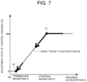
- a temporal change in the control gain Gain as the adjustment rate of a control variable of the prime mover 1 in the example shown in FIG. 6 will be explained in more detail with reference to FIG. 7 .
- the adjustment rate of the control variable is 100% at point t 1 , and starts to be reduced from point t 1 .
- the adjustment rate of the control variable is reduced to 0% at point t 2 .
- a temporal change in the required acceleration G in the example shown in FIG. 6 will be explained in more detail with reference to FIG. 8 .
- the accelerator pedal 4 is depressed at point t 0 so that the required acceleration G is increased. Consequently, the acceleration enrichment control is commenced from point t 0 .
- the required acceleration G decreases gradually with an increase in the speed of the vehicle Ve, and when the required acceleration G decreases to the starting magnitude B at point t 1 , the adjustment rate reducing control is commenced. Consequently, the corrected target acceleration Gh is reduced from point t 1 with a reduction in the acceleration enrichment value Gsgain. The corrected target acceleration Gh is further reduced to the basic target acceleration Gb at point t 2 which is immediately before the required acceleration G decreases to zero, and the acceleration enrichment control is terminated.
- the control system is configured to execute the acceleration enrichment control when a large acceleration is required by the driver.
- the driving force to propel the vehicle Ve is controlled based on the corrected target acceleration Gh calculated by adding the acceleration enrichment value Gsgain calculated taking account of the driver's intension to the basic target acceleration Gb.
- the acceleration can be enhanced accurately in line with the driver's intension.
- the target acceleration is reduced from the corrected target acceleration Gh to the basic target acceleration Gb when the acceleration of the vehicle Ve decreases to the terminating magnitude A which is greater than zero.
- the jerk is changed before the acceleration of the vehicle Ve decreases to zero, and the acceleration further decreases smoothly toward zero at the reduction rate governed by the basic target acceleration. For this reason, the driver will not be urged to operate the accelerator pedal 4 unnecessarily when the acceleration enrichment control is terminated and the vehicle Ve starts coasting.
- FIG. 10 there is shown another comparison between the prior art and the exemplary embodiment of the present disclosure.
- the acceleration enrichment value Gsgain is calculated based on the difference Gs between the basic target acceleration Gb and the intended acceleration Gi.
- the driving force can be controlled accurately in line with the intended acceleration Gi.
- the acceleration increased by depressing the accelerator pedal is reduced abruptly in spite of maintaining the position of the accelerator pedal. That is, according to the prior art, the acceleration is reduced against the driver's will.
- the acceleration increased by depressing the accelerator pedal is not reduced abruptly as long as the position of the accelerator pedal is maintained. Therefore, the acceleration can be increased sharply in line with the driver's intension even if the accelerator pedal 4 is depressed deeply at a high speed, but the acceleration will not be reduced undesirably until the adjustment rate of the control variable is reduced.
- FIG. 11 there is shown a second example of a temporal change in the adjustment rate during execution of the routine shown in FIG. 3 .
- the accelerator pedal 4 is depressed at point t 0 at a rate faster than the predetermined speed ß so that the required acceleration G is increased to the predetermined value a or greater.
- the acceleration enrichment flag is turned on to commence the acceleration enrichment control from point t 0 , and the adjustment rate of the control variable is increased to 100%.
- the basic target acceleration Gb is reduced from point t 0 with an increase in the speed of the vehicle Ve.
- the accelerator pedal 4 is returned from point t 1 , and the basic target acceleration Gb falls to the starting magnitude B at point t 1 so that the adjustment rate of the control variable starts to be reduced. Consequently, the acceleration enrichment value Gsgain is reduced from point t 1 at a rate faster than that in the first example so that the corrected target acceleration Gh is reduced from point t 1 a rate faster than that in the first example.
- the basic target acceleration Gb is reduced at a faster rate with a reduction in depression of the accelerator pedal 4 , and when the basic target acceleration Gb is reduced to the terminating magnitude A at point t 2 , the adjustment rate of the control variable is reduced to 0%. Consequently, the acceleration enrichment flag is turned off at point t 2 .
- the adjustment rate reducing control is also terminated before the required acceleration G is reduced to zero, and the required acceleration G as the target acceleration is reduced at a same rate as the reduction rate of the basic target acceleration Gb after point t 2 . According to the second example shown in FIG. 11 , therefore, the acceleration of the vehicle Ve will also not be reduced stepwise when the acceleration enrichment control is terminated.
- a temporal change in the control gain Gain as the adjustment rate of a control variable of the prime mover 1 in the second example shown in FIG. 11 will be explained in more detail with reference to FIG. 12 .
- the adjustment rate of the control variable is 100% at point t 1 , and starts to be reduced from point t 1 .
- the adjustment rate of the control variable is reduced to 0% at point t 2 , and maintained to 0% until point t 3 .
- a temporal change in the required acceleration G in the second example shown in FIG. 11 will be explained in more detail with reference to FIG. 13 .
- the accelerator pedal 4 is depressed at point t 0 so that the required acceleration G is increased.
- the acceleration enrichment control is commenced from point t 0 .
- the required acceleration G decreases gradually with an increase in the speed of the vehicle Ve, and when the required acceleration G decreases to the starting magnitude B at point t 1 , the adjustment rate reducing control is commenced. Consequently, the corrected target acceleration Gh is reduced from point t 1 with a reduction in the acceleration enrichment value Gsgain.
- the corrected target acceleration Gh is further reduced with a reduction in depression of the accelerator pedal 4 to the basic target acceleration Gb when the required acceleration G decreases to the terminating magnitude A at point t 2 . Consequently, the acceleration enrichment control is terminated at point t 2 , and then, the required acceleration G turns into the negative value.
- FIG. 14 there is shown a third example of a temporal change in the adjustment rate during execution of the routine shown in FIG. 3 .
- the accelerator pedal 4 is depressed at point t 0 at a rate faster than the predetermined speed ß so that the required acceleration G is increased to the predetermined value a or greater. Consequently, the acceleration enrichment control is commenced from point t 0 .
- the accelerator pedal 4 is also returned from point t 1 , and the corrected target acceleration Gh is also reduced to the basic target acceleration Gb at point t 2 . Then, the accelerator pedal 4 is returned close to the initial position at point t 3 so that the required acceleration G turns into a negative value.
- the acceleration enrichment control has already been terminated before the acceleration is reduced to zero, and hence the acceleration of the vehicle Ve will not be reduced stepwise by an undesirable change in the jerk.
- the accelerator pedal 4 is depressed again at point t 3 .
- the basic target acceleration Gb is employed as the required acceleration G to increase the acceleration in response to the depression of the accelerator pedal 4 . Therefore, the acceleration of the vehicle Ve can be increased naturally in response to an operation of the accelerator pedal 4 .
- a temporal change in the control gain Gain as the adjustment rate of a control variable of the prime mover 1 in the third example shown in FIG. 14 will be explained in more detail with reference to FIG. 15 .
- the adjustment rate of the control variable is 100% at point t 1 , and starts to be reduced from point t 1 .
- the adjustment rate of the control variable is reduced to 0% at point t 2 , and the required acceleration G turns into the negative value after point t 2 .
- the required acceleration G does not exceed the predetermined value a, and the operating speed of the accelerator pedal 4 does not exceed the predetermined speed S. Therefore, the adjustment rate of the control variable is maintained to 0% after point t 2 .
- a temporal change in the required acceleration G in the third example shown in FIG. 11 will be explained in more detail with reference to FIG. 16 .
- the accelerator pedal 4 is depressed at point t 0 so that the required acceleration G is increased. Consequently, the acceleration enrichment control is commenced from point t 0 .
- the required acceleration G decreases gradually with an increase in the speed of the vehicle Ve, and when the required acceleration G decreases to the starting magnitude B at point t 1 , the adjustment rate reducing control is commenced. Consequently, the corrected target acceleration Gh is reduced from point t 1 with a reduction in the acceleration enrichment value Gsgain.
- the corrected target acceleration Gh is further reduced with a reduction in the depression of the accelerator pedal 4 to the basic target acceleration Gb when the required acceleration G decreases to the terminating magnitude A at point t 2 . Consequently, the acceleration enrichment control is terminated at point t 2 , and then, the required acceleration G turns into the negative value. Thereafter, the accelerator pedal 4 is depressed again at point t 3 but the required acceleration G has not yet exceeded the predetermined value a, and the operating speed of the accelerator pedal 4 has not yet exceeded the predetermined speed S. Therefore, the required acceleration G increases mildly based on the basic target acceleration Gb in response to an increase in depression of the accelerator pedal 4 .
- FIG. 17 there is shown a fourth example of a temporal change in the adjustment rate during execution of the routine shown in FIG. 3 .
- the accelerator pedal 4 is depressed at point t 0 at a rate faster than the predetermined speed ß so that the required acceleration G is increased to the predetermined value a or greater. Consequently, the acceleration enrichment control is commenced from point t 0 .
- the accelerator pedal 4 is also returned from point t 1 , and consequently, the adjustment rate of the control variable starts to be reduced so that the acceleration enrichment value Gsgain is reduced from point t 1 .
- the accelerator pedal 4 is depressed again at point t 2 before the corrected target acceleration Gh is reduced to the basic target acceleration Gb. Consequently, the required acceleration G and the adjustment rate of the control variable are increased from point t 2 in response to an increase in depression of the accelerator pedal 4 . Eventually, the adjustment rate of the control variable being reduced is increased to 100% again at point t 3 , and maintained to 100% after point t 3 as long as the accelerator pedal 4 is depressed.
- the acceleration enrichment flag continues to be turned on so that the acceleration of the vehicle Ve is controlled based on the corrected target acceleration Gh after point t 0 .
- a temporal change in the control gain Gain as the adjustment rate of a control variable of the prime mover 1 in the fourth example shown in FIG. 17 will be explained in more detail with reference to FIG. 18 .
- the adjustment rate of the control variable is 100% at point t 1 , and starts to be reduced from point t 1 .
- the adjustment rate of the control variable is reduced close to 0% at point t 2 .
- the accelerator pedal 4 being returned is depressed again so that the adjustment rate of the control variable is increased to 100% again at point t 3 .
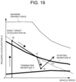
- a temporal change in the required acceleration G in the fourth example shown in FIG. 17 will be explained in more detail with reference to FIG. 19 .
- FIG. 19 In the fourth example shown in FIG.
- the accelerator pedal 4 is depressed at point t 0 so that the required acceleration G is increased. Consequently, the acceleration enrichment control is commenced from point t 0 . Then, the required acceleration G decreases gradually with an increase in the speed of the vehicle Ve, and when the required acceleration G decreases to the starting magnitude B at point t 1 , the adjustment rate reducing control is commenced. Consequently, the corrected target acceleration Gh is reduced from point t 1 with a reduction in the acceleration enrichment value Gsgain. The accelerator pedal 4 being returned is depressed again at point t 2 before the corrected target acceleration Gh is reduced to the basic target acceleration Gb. Consequently, the required acceleration G is increased from point t 2 in response to an increase in depression of the accelerator pedal 4 .
- the acceleration enrichment control is executed in the same manner as the case of travelling on a flat road also when travelling uphill whose road grade is steeper than a predetermined road grade, the acceleration enrichment control would be continued undesirably even if the driver does not intend to accelerate the vehicle Ve any longer. According to another example, therefore, the acceleration enrichment control is executed taking account of a road grade.
- FIG. 20 there is shown another example of the routine executed by the ECU 7 .
- the routine executed by the ECU 7 In the following descriptions, explanations for the steps in common with those in the routine shown in FIG. 3 will be simplified.
- step S 100 it is determined whether the driver intends to accelerate the vehicle Ve. Specifically, it is determined whether the required acceleration G is greater than the predetermined value a, and whether the operating speed of the accelerator pedal 4 is faster than the predetermined speed S. According to another example, the required acceleration G as a target acceleration is calculated based on a position of the accelerator pedal 4 , a current speed of the vehicle Ve, and a road grade with reference to the map shown in FIG. 2 . The required acceleration G thus calculated with reference to the map shown in FIG. 2 is a so-called static acceleration, and will be employed as the basic target acceleration Gb at the subsequent steps.
- step S 100 If the required acceleration G is less than the predetermined value a, or if the operating speed of the accelerator pedal 4 is slower than the predetermined speed ß so that the answer of step S 100 is NO, the ECU 7 determines that the driver does not intend to accelerate the vehicle Ve, and the routine returns.
- the ECU 7 determines that the driver intends to accelerate the vehicle Ve.
- the routine progresses to step S 200 to calculate the intended acceleration Gi required by the driver.
- the required acceleration G is determined temporarily based on a position of the accelerator pedal 4 , a speed of the vehicle Ve, and a road grade.
- the intended acceleration Gi is calculated further based on a dynamic parameter such as an operating speed of the accelerator pedal 4 , in addition to the position of the accelerator pedal 4 , the speed of the vehicle Ve, and the road grade. That is, the intended acceleration Gi is calculated taking into account the intension of the driver to accelerate the vehicle Ve.
- the upper limit value or the lower limit value of the intended acceleration Gi is calculated. For example, if the intended acceleration Gi calculated at step S 200 is greater than the maximum acceleration Gmax governed by a structure of the vehicle Ve, the intended acceleration Gi will be corrected to the maximum acceleration Gmax. By contrast, if the intended acceleration Gi calculated at step S 200 is equal to or less than the maximum acceleration Gmax, the intended acceleration Gi will not be corrected and maintained to the value calculated at step S 200 .
- the basic target acceleration Gb calculated at step S 1 corresponds to the lower limit value of the intended acceleration Gi.
- the maximum acceleration Gmax is calculated based on a maximum speed of the vehicle Ve and a road grade.
- the corrected target acceleration Gh is calculated by adding the acceleration enrichment value Gsgain calculated at step S 500 to the basic target acceleration Gb.
- the corrected target acceleration Gh is employed as a final value of the required acceleration G.
- the corrected target acceleration Gh is converted into the target driving force taking into consideration a weight of the vehicle Ve, a gear ratio, a diameter of each tire, a running resistance etc., and the vehicle Ve is propelled by the target driving force thus calculated so as to achieve the corrected target acceleration Gh.
- step S 800 it is determined at step S 800 whether the control gain Gain (i.e., the adjustment rate of the control variable) is reduced to zero. If the control gain Gain has been reduced to zero so that the answer of step S 800 is YES, the routine returns. That is, the acceleration enrichment control is terminated, and the acceleration will be controlled based on the basic target acceleration Gb. By contrast, if the control gain Gain has not yet been reduced to zero so that the answer of step S 800 is NO, such determination at step S 800 will be repeated until the control gain Gain is reduced to zero.
- the control gain Gain i.e., the adjustment rate of the control variable
- the required acceleration G is calculated taking account of a road grade.
- FIG. 21 there is shown a comparison between a conventional acceleration enrichment control according to the prior art and another example shown in FIG. 20 .
- the acceleration enrichment control is executed without taking account of a road grade.
- an accelerator pedal is depressed at point t 10 ′ so that the acceleration enrichment control is commenced.
- the road grade increases to A % from point t 11 ′ to point t 12 ′. Consequently, a corrected target acceleration as a required acceleration falls below 0G at the grade of A % immediately after point t 12 ′, and eventually falls to a basic target acceleration at point t 13 ′.
- the driver no longer intends to accelerate the vehicle Ve at the point when the required acceleration falls below 0G at the grade of A %, however, the acceleration is still enhanced until point t 13 ′ against the driver's will.
- the accelerator pedal 4 is also depressed at point t 10 so that the acceleration enrichment control is commenced and the road grade also increases to A % from point t 11 to point t 12 .
- the corrected target acceleration Gh is reduced to the basic target acceleration Gb at point t 12 when the road grade increases to A %. That is, the ECU 7 determines that the driver no longer intends to accelerate the vehicle Ve when the acceleration of the vehicle Ve decreases to 0 on the uphill.
- the acceleration enrichment value Gsgain is reduced in such a manner that the corrected target acceleration Gh is reduced to the basic target acceleration Gb at a greater magnitude of the acceleration decreasing while the accelerator pedal 4 is maintained to a predetermined position, compared to the case of travelling on a flat road. According to another example, therefore, the acceleration of the vehicle Ve may be controlled accurately in line with the driver's intention even when travelling uphill.
Landscapes
- Engineering & Computer Science (AREA)
- Mechanical Engineering (AREA)
- Transportation (AREA)
- Automation & Control Theory (AREA)
- Combustion & Propulsion (AREA)
- Chemical & Material Sciences (AREA)
- Mathematical Physics (AREA)
- Physics & Mathematics (AREA)
- General Engineering & Computer Science (AREA)
- Human Computer Interaction (AREA)
- Power Engineering (AREA)
- Control Of Throttle Valves Provided In The Intake System Or In The Exhaust System (AREA)
- Control Of Vehicle Engines Or Engines For Specific Uses (AREA)
- Control Of Driving Devices And Active Controlling Of Vehicle (AREA)
Abstract
Description
Gh=Gb+Gsgain.
That is, the basic target acceleration Gb is corrected to be increased by the acceleration enrichment value Gsgain. The corrected target acceleration Gh thus calculated at step S6 will be employed as a final value of the required acceleration G.
Claims (3)
Applications Claiming Priority (2)
| Application Number | Priority Date | Filing Date | Title |
|---|---|---|---|
| JP2021-029951 | 2021-02-26 | ||
| JP2021029951A JP7604944B2 (en) | 2021-02-26 | 2021-02-26 | Vehicle driving force control device |
Publications (2)
| Publication Number | Publication Date |
|---|---|
| US20220274615A1 US20220274615A1 (en) | 2022-09-01 |
| US12017669B2 true US12017669B2 (en) | 2024-06-25 |
Family
ID=80461225
Family Applications (1)
| Application Number | Title | Priority Date | Filing Date |
|---|---|---|---|
| US17/585,102 Active 2042-09-04 US12017669B2 (en) | 2021-02-26 | 2022-01-26 | Driving force control system for vehicle |
Country Status (4)
| Country | Link |
|---|---|
| US (1) | US12017669B2 (en) |
| EP (1) | EP4049911B1 (en) |
| JP (1) | JP7604944B2 (en) |
| CN (1) | CN114987475B (en) |
Families Citing this family (4)
| Publication number | Priority date | Publication date | Assignee | Title |
|---|---|---|---|---|
| JP2024085013A (en) * | 2022-12-14 | 2024-06-26 | カワサキモータース株式会社 | Vehicle control device and vehicle control method |
| CN115837844B (en) * | 2022-12-16 | 2026-03-17 | 河南科技大学 | A single-pedal electric direct-drive vehicle control method |
| JP2025126795A (en) * | 2024-02-19 | 2025-08-29 | トヨタ自動車株式会社 | Acceleration-deceleration control apparatus |
| JP2026048289A (en) * | 2024-09-05 | 2026-03-17 | マツダ株式会社 | Vehicle control system and control method |
Citations (10)
| Publication number | Priority date | Publication date | Assignee | Title |
|---|---|---|---|---|
| JP2004276669A (en) | 2003-03-13 | 2004-10-07 | Nissan Motor Co Ltd | Vehicle driving force control device |
| JP2007155643A (en) * | 2005-12-08 | 2007-06-21 | Toyota Motor Corp | Automatic operation control device for vehicle tester |
| JP2007248160A (en) * | 2006-03-14 | 2007-09-27 | Toyota Motor Corp | Device for estimating vehicle weight and road gradient |
| JP2008055994A (en) * | 2006-08-30 | 2008-03-13 | Toyota Motor Corp | Vehicle braking / driving force control device |
| US20090048751A1 (en) * | 2007-08-10 | 2009-02-19 | Denso Corporation | Method and apparatus for controlling acceleration of a vehicle |
| JP2010285139A (en) * | 2009-05-15 | 2010-12-24 | Toyota Motor Corp | Vehicle control device |
| WO2011089468A1 (en) | 2010-01-19 | 2011-07-28 | Toyota Jidosha Kabushiki Kaisha | Vehicle control system |
| DE102011103604A1 (en) | 2011-06-08 | 2012-02-16 | Daimler Ag | Method for supporting driver of motor car during oncoming traffic situation, involves comparing operation quality of accelerator pedals of motor car with set of criteria for recognizing strong acceleration request |
| JP5974916B2 (en) * | 2013-01-30 | 2016-08-23 | トヨタ自動車株式会社 | Vehicle speed control device |
| US20160281621A1 (en) * | 2015-03-26 | 2016-09-29 | Toyota Jidosha Kabushiki Kaisha | Vehicle speed limit apparatus |
Family Cites Families (6)
| Publication number | Priority date | Publication date | Assignee | Title |
|---|---|---|---|---|
| JP4446978B2 (en) * | 2006-04-28 | 2010-04-07 | トヨタ自動車株式会社 | Vehicle driving force control device |
| JP5780837B2 (en) * | 2011-06-01 | 2015-09-16 | 日野自動車株式会社 | VEHICLE CONTROL DEVICE, VEHICLE, VEHICLE CONTROL METHOD, AND PROGRAM |
| DE102013010542A1 (en) * | 2013-06-25 | 2015-06-18 | Daimler Ag | Method for controlling a drive machine |
| DE112013007223T5 (en) * | 2013-07-11 | 2016-04-28 | Toyota Jidosha Kabushiki Kaisha | Vehicle control system |
| RU2699204C1 (en) * | 2015-11-09 | 2019-09-03 | Ниссан Мотор Ко., Лтд. | Braking/driving force control method and brake/driving force control device |
| JP6784149B2 (en) * | 2016-11-11 | 2020-11-11 | 三菱自動車工業株式会社 | Vehicle driving force control device |
-
2021
- 2021-02-26 JP JP2021029951A patent/JP7604944B2/en active Active
-
2022
- 2022-01-26 US US17/585,102 patent/US12017669B2/en active Active
- 2022-02-25 CN CN202210174911.0A patent/CN114987475B/en active Active
- 2022-02-25 EP EP22158922.9A patent/EP4049911B1/en active Active
Patent Citations (12)
| Publication number | Priority date | Publication date | Assignee | Title |
|---|---|---|---|---|
| JP2004276669A (en) | 2003-03-13 | 2004-10-07 | Nissan Motor Co Ltd | Vehicle driving force control device |
| JP2007155643A (en) * | 2005-12-08 | 2007-06-21 | Toyota Motor Corp | Automatic operation control device for vehicle tester |
| JP2007248160A (en) * | 2006-03-14 | 2007-09-27 | Toyota Motor Corp | Device for estimating vehicle weight and road gradient |
| JP2008055994A (en) * | 2006-08-30 | 2008-03-13 | Toyota Motor Corp | Vehicle braking / driving force control device |
| US20090048751A1 (en) * | 2007-08-10 | 2009-02-19 | Denso Corporation | Method and apparatus for controlling acceleration of a vehicle |
| JP2010285139A (en) * | 2009-05-15 | 2010-12-24 | Toyota Motor Corp | Vehicle control device |
| WO2011089468A1 (en) | 2010-01-19 | 2011-07-28 | Toyota Jidosha Kabushiki Kaisha | Vehicle control system |
| JP2011148342A (en) | 2010-01-19 | 2011-08-04 | Toyota Motor Corp | Vehicle control device |
| US20120296541A1 (en) * | 2010-01-19 | 2012-11-22 | Toyota Jidosha Kabushiki Kaisha | Vehicle control system |
| DE102011103604A1 (en) | 2011-06-08 | 2012-02-16 | Daimler Ag | Method for supporting driver of motor car during oncoming traffic situation, involves comparing operation quality of accelerator pedals of motor car with set of criteria for recognizing strong acceleration request |
| JP5974916B2 (en) * | 2013-01-30 | 2016-08-23 | トヨタ自動車株式会社 | Vehicle speed control device |
| US20160281621A1 (en) * | 2015-03-26 | 2016-09-29 | Toyota Jidosha Kabushiki Kaisha | Vehicle speed limit apparatus |
Non-Patent Citations (2)
| Title |
|---|
| Machine translation of JP2007155643A (Year: 2007). * |
| Machine translation of JP2008055994A (Year: 2008). * |
Also Published As
| Publication number | Publication date |
|---|---|
| CN114987475A (en) | 2022-09-02 |
| JP2022131152A (en) | 2022-09-07 |
| CN114987475B (en) | 2025-07-15 |
| EP4049911B1 (en) | 2023-11-22 |
| JP7604944B2 (en) | 2024-12-24 |
| EP4049911A1 (en) | 2022-08-31 |
| US20220274615A1 (en) | 2022-09-01 |
Similar Documents
| Publication | Publication Date | Title |
|---|---|---|
| US12017669B2 (en) | Driving force control system for vehicle | |
| US10525968B2 (en) | Method for controlling a drive device of a hybrid vehicle and hybrid vehicle | |
| US11124174B2 (en) | Vehicle control system | |
| US5905349A (en) | Method of controlling electric motor torque in an electric vehicle | |
| US10800400B2 (en) | Control system for hybrid vehicle | |
| US20200254983A1 (en) | Brake force control system for vehicle | |
| US6262491B1 (en) | Control system for hybrid vehicle | |
| US6740987B2 (en) | Control device for hybrid vehicle | |
| US6356818B1 (en) | Control apparatus for hybrid vehicle | |
| US11952009B2 (en) | Driving force control system for vehicle | |
| US11807237B2 (en) | Vehicle control system | |
| JP7070325B2 (en) | Vehicle control device | |
| US6570266B1 (en) | Control apparatus for hybrid vehicle | |
| US6641501B2 (en) | Control apparatus for hybrid vehicle | |
| US20200309042A1 (en) | Driving force control apparatus for vehicle | |
| US20040148071A1 (en) | Controlle for hybrid vehicle | |
| US6216465B1 (en) | Control system for hybrid vehicle | |
| US11485347B2 (en) | Drive force control system for vehicle | |
| JP2020100349A (en) | Vehicle control device | |
| US12291127B2 (en) | Vehicle gear-shifting control apparatus | |
| US11891065B2 (en) | Vehicle gear-shifting control apparatus | |
| JP5614237B2 (en) | Vehicle travel control device | |
| JP2019107980A (en) | Vehicular control device | |
| JP2021109627A (en) | Vehicle control device | |
| US20230098578A1 (en) | Vehicle control device |
Legal Events
| Date | Code | Title | Description |
|---|---|---|---|
| AS | Assignment |
Owner name: TOYOTA JIDOSHA KABUSHIKI KAISHA, JAPAN Free format text: ASSIGNMENT OF ASSIGNORS INTEREST;ASSIGNORS:KUMAGAI, KUNINORI;YAMANAKA, SATOSHI;METSUGI, HIROMITSU;SIGNING DATES FROM 20220107 TO 20220110;REEL/FRAME:058926/0911 |
|
| STPP | Information on status: patent application and granting procedure in general |
Free format text: DOCKETED NEW CASE - READY FOR EXAMINATION |
|
| STPP | Information on status: patent application and granting procedure in general |
Free format text: NON FINAL ACTION MAILED |
|
| STPP | Information on status: patent application and granting procedure in general |
Free format text: RESPONSE TO NON-FINAL OFFICE ACTION ENTERED AND FORWARDED TO EXAMINER |
|
| STPP | Information on status: patent application and granting procedure in general |
Free format text: FINAL REJECTION MAILED |
|
| STPP | Information on status: patent application and granting procedure in general |
Free format text: RESPONSE AFTER FINAL ACTION FORWARDED TO EXAMINER |
|
| STPP | Information on status: patent application and granting procedure in general |
Free format text: NOTICE OF ALLOWANCE MAILED -- APPLICATION RECEIVED IN OFFICE OF PUBLICATIONS |
|
| STPP | Information on status: patent application and granting procedure in general |
Free format text: PUBLICATIONS -- ISSUE FEE PAYMENT VERIFIED |
|
| STCF | Information on status: patent grant |
Free format text: PATENTED CASE |