US12012647B2 - Additively manufactured oxide dispersion strengthened medium entropy alloys for high temperature applications - Google Patents
Additively manufactured oxide dispersion strengthened medium entropy alloys for high temperature applications Download PDFInfo
- Publication number
- US12012647B2 US12012647B2 US16/906,319 US202016906319A US12012647B2 US 12012647 B2 US12012647 B2 US 12012647B2 US 202016906319 A US202016906319 A US 202016906319A US 12012647 B2 US12012647 B2 US 12012647B2
- Authority
- US
- United States
- Prior art keywords
- composite material
- alloy
- particles
- ceramic particles
- material according
- Prior art date
- Legal status (The legal status is an assumption and is not a legal conclusion. Google has not performed a legal analysis and makes no representation as to the accuracy of the status listed.)
- Active, expires
Links
Images


Classifications
-
- C—CHEMISTRY; METALLURGY
- C22—METALLURGY; FERROUS OR NON-FERROUS ALLOYS; TREATMENT OF ALLOYS OR NON-FERROUS METALS
- C22C—ALLOYS
- C22C30/00—Alloys containing less than 50% by weight of each constituent
-
- B—PERFORMING OPERATIONS; TRANSPORTING
- B22—CASTING; POWDER METALLURGY
- B22F—WORKING METALLIC POWDER; MANUFACTURE OF ARTICLES FROM METALLIC POWDER; MAKING METALLIC POWDER; APPARATUS OR DEVICES SPECIALLY ADAPTED FOR METALLIC POWDER
- B22F1/00—Metallic powder; Treatment of metallic powder, e.g. to facilitate working or to improve properties
- B22F1/05—Metallic powder characterised by the size or surface area of the particles
-
- B—PERFORMING OPERATIONS; TRANSPORTING
- B22—CASTING; POWDER METALLURGY
- B22F—WORKING METALLIC POWDER; MANUFACTURE OF ARTICLES FROM METALLIC POWDER; MAKING METALLIC POWDER; APPARATUS OR DEVICES SPECIALLY ADAPTED FOR METALLIC POWDER
- B22F1/00—Metallic powder; Treatment of metallic powder, e.g. to facilitate working or to improve properties
- B22F1/07—Metallic powder characterised by particles having a nanoscale microstructure
-
- B—PERFORMING OPERATIONS; TRANSPORTING
- B22—CASTING; POWDER METALLURGY
- B22F—WORKING METALLIC POWDER; MANUFACTURE OF ARTICLES FROM METALLIC POWDER; MAKING METALLIC POWDER; APPARATUS OR DEVICES SPECIALLY ADAPTED FOR METALLIC POWDER
- B22F1/00—Metallic powder; Treatment of metallic powder, e.g. to facilitate working or to improve properties
- B22F1/16—Metallic particles coated with a non-metal
-
- B—PERFORMING OPERATIONS; TRANSPORTING
- B33—ADDITIVE MANUFACTURING TECHNOLOGY
- B33Y—ADDITIVE MANUFACTURING, i.e. MANUFACTURING OF THREE-DIMENSIONAL [3D] OBJECTS BY ADDITIVE DEPOSITION, ADDITIVE AGGLOMERATION OR ADDITIVE LAYERING, e.g. BY 3D PRINTING, STEREOLITHOGRAPHY OR SELECTIVE LASER SINTERING
- B33Y70/00—Materials specially adapted for additive manufacturing
- B33Y70/10—Composites of different types of material, e.g. mixtures of ceramics and polymers or mixtures of metals and biomaterials
-
- B—PERFORMING OPERATIONS; TRANSPORTING
- B22—CASTING; POWDER METALLURGY
- B22F—WORKING METALLIC POWDER; MANUFACTURE OF ARTICLES FROM METALLIC POWDER; MAKING METALLIC POWDER; APPARATUS OR DEVICES SPECIALLY ADAPTED FOR METALLIC POWDER
- B22F10/00—Additive manufacturing of workpieces or articles from metallic powder
- B22F10/20—Direct sintering or melting
- B22F10/28—Powder bed fusion, e.g. selective laser melting [SLM] or electron beam melting [EBM]
-
- B—PERFORMING OPERATIONS; TRANSPORTING
- B22—CASTING; POWDER METALLURGY
- B22F—WORKING METALLIC POWDER; MANUFACTURE OF ARTICLES FROM METALLIC POWDER; MAKING METALLIC POWDER; APPARATUS OR DEVICES SPECIALLY ADAPTED FOR METALLIC POWDER
- B22F2302/00—Metal Compound, non-Metallic compound or non-metal composition of the powder or its coating
- B22F2302/25—Oxide
-
- B—PERFORMING OPERATIONS; TRANSPORTING
- B22—CASTING; POWDER METALLURGY
- B22F—WORKING METALLIC POWDER; MANUFACTURE OF ARTICLES FROM METALLIC POWDER; MAKING METALLIC POWDER; APPARATUS OR DEVICES SPECIALLY ADAPTED FOR METALLIC POWDER
- B22F2304/00—Physical aspects of the powder
- B22F2304/10—Micron size particles, i.e. above 1 micrometer up to 500 micrometer
-
- B—PERFORMING OPERATIONS; TRANSPORTING
- B33—ADDITIVE MANUFACTURING TECHNOLOGY
- B33Y—ADDITIVE MANUFACTURING, i.e. MANUFACTURING OF THREE-DIMENSIONAL [3D] OBJECTS BY ADDITIVE DEPOSITION, ADDITIVE AGGLOMERATION OR ADDITIVE LAYERING, e.g. BY 3D PRINTING, STEREOLITHOGRAPHY OR SELECTIVE LASER SINTERING
- B33Y10/00—Processes of additive manufacturing
-
- B—PERFORMING OPERATIONS; TRANSPORTING
- B33—ADDITIVE MANUFACTURING TECHNOLOGY
- B33Y—ADDITIVE MANUFACTURING, i.e. MANUFACTURING OF THREE-DIMENSIONAL [3D] OBJECTS BY ADDITIVE DEPOSITION, ADDITIVE AGGLOMERATION OR ADDITIVE LAYERING, e.g. BY 3D PRINTING, STEREOLITHOGRAPHY OR SELECTIVE LASER SINTERING
- B33Y80/00—Products made by additive manufacturing
-
- Y—GENERAL TAGGING OF NEW TECHNOLOGICAL DEVELOPMENTS; GENERAL TAGGING OF CROSS-SECTIONAL TECHNOLOGIES SPANNING OVER SEVERAL SECTIONS OF THE IPC; TECHNICAL SUBJECTS COVERED BY FORMER USPC CROSS-REFERENCE ART COLLECTIONS [XRACs] AND DIGESTS
- Y02—TECHNOLOGIES OR APPLICATIONS FOR MITIGATION OR ADAPTATION AGAINST CLIMATE CHANGE
- Y02P—CLIMATE CHANGE MITIGATION TECHNOLOGIES IN THE PRODUCTION OR PROCESSING OF GOODS
- Y02P10/00—Technologies related to metal processing
- Y02P10/25—Process efficiency
-
- Y—GENERAL TAGGING OF NEW TECHNOLOGICAL DEVELOPMENTS; GENERAL TAGGING OF CROSS-SECTIONAL TECHNOLOGIES SPANNING OVER SEVERAL SECTIONS OF THE IPC; TECHNICAL SUBJECTS COVERED BY FORMER USPC CROSS-REFERENCE ART COLLECTIONS [XRACs] AND DIGESTS
- Y10—TECHNICAL SUBJECTS COVERED BY FORMER USPC
- Y10T—TECHNICAL SUBJECTS COVERED BY FORMER US CLASSIFICATION
- Y10T428/00—Stock material or miscellaneous articles
- Y10T428/12—All metal or with adjacent metals
- Y10T428/12014—All metal or with adjacent metals having metal particles
Definitions
- additive manufacturing currently facilitates new avenues for component fabrication that have not been fully explored. Additive manufacturing techniques have broadened many aspects of component design, enabled part count reduction, and decreased commissioning time for prospective hardware and industrial applications. Currently, the majority of research relating to AM of metallic materials has been conducted on traditional alloys.
- L-PBF Laser powder bed fusion
- MPEA multi-principal element alloy
- Dispersion strengthening primarily through the use of ceramics such as oxides, is a strengthening technique that was explored in the 1980's, and was expected to replace existing Ni-base superalloys in high temperature applications, such as extreme gas turbine environments, and to replace stainless steels used in nuclear applications, such as advanced fission or fusion reactors.
- DS alloys typically have been manufactured through a mechanical alloying (MA) process, in which the dispersoids were alloyed with the metallic powder through high energy ball milling.
- MA mechanical alloying
- This process resulted in metal alloy particles being pulverized and broken down, thus changing the shape of the alloy particles from rounded to irregularly shaped.
- the irregularly shaped particles had to be sifted out, and therefore, the alloy was significantly more expensive to fabricate compared to more conventional superalloys and is unsuitable for AM. Further, this process resulted in some level of contamination of the alloy from material from the balls used in ball milling.
- An additive manufacturing powdered composite material includes metal particles coated with a coating of ceramic particles.
- the metal particles include an alloy including 30-35 wt % cobalt, 26-31 wt % chromium, 0-3.0 wt % rhenium, 0-1.0 wt % aluminum, 0.01-0.1 wt % carbon, 0-1.0 wt % titanium, and nickel making up a balance of a weight of the alloy.
- the ceramic particles include yttrium oxide, halfnium oxide, zirconium oxide, or combinations thereof.
- An additively manufactured component includes ceramic particles dispersed in a metal matrix.
- the metal matrix includes an alloy including 30-35 wt % cobalt, 26-31 wt % chromium, 0-3.0 wt % rhenium, 0-1.0 wt % aluminum, 0.01-0.1 wt % carbon, 0-1.0 wt % titanium, and nickel making up a balance of a weight of the alloy.
- the ceramic particles include yttrium oxide, halfnium oxide, zirconium oxide, or combinations thereof.
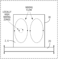
- FIG. 1 is a schematic side view of a resonant acoustic mixing process according to the present subject matter.
- FIG. 2 is a schematic view of a metal particle during acoustic mixing with ceramic particles according to the present subject matter.
- FIG. 3 is a schematic view of a composite particle according to the present subject matter.
- FIG. 4 is an SEM image of a composite particle according to the present subject matter.
- FIG. 5 is a high-resolution image of the composite particles of FIG. 4 .
- FIG. 6 is an EDS image of a composite particle according to the present subject matter.
- FIG. 7 is a photograph of metal powder and ceramic powder in a mixing container according to the present subject matter.
- FIG. 8 is a photograph of a composite material according to the present subject matter.
- FIG. 9 is an optical image of metal particles before acoustic mixing with ceramic particles according to the present subject matter.
- FIG. 10 is an optical image of a composite material according to the present subject matter.
- FIG. 11 is an SEM image of the metal particles of FIG. 9 before acoustic mixing with ceramic particles.
- FIG. 12 is an SEM image of the composite material of FIG. 10 .
- FIG. 13 is a schematic side view of a laser powder bed fusion process according to the present subject matter.
- FIG. 14 is a schematic detailed view of a laser powder bed fusion process according to the present subject matter.
- FIG. 15 is an SEM image of an additively manufactured component according to the present subject matter.
- FIG. 16 is a high-resolution SEM image of the additively manufactured component of FIG. 15 .
- FIG. 17 are electron back scatter diffraction maps of inventive and comparative examples of additively manufactured components according to the present subject matter.
- FIG. 18 is a stress-strain curve of comparative additively manufactured components subjected to tensile tests.
- FIG. 19 is a stress-strain curve of inventive additively manufactured components subjected to tensile tests.
- FIG. 20 is a stress-strain curve of an inventive and a comparative additively manufactured component subjected to tensile tests.
- FIG. 21 is a stress-strain curve of inventive and comparative additively manufactured components subjected to tensile tests.
- FIG. 22 is a plot showing the high temperature properties of an inventive dispersion strengthened medium entropy alloy made according the present subject matter, compared to that of mechanically alloyed dispersion strengthened superalloys and conventional wrought superalloys.
- High temperature materials include Refractory Metals, Carbon-Carbon composites, ceramic matrix composites (CMC's), Ni-base superalloys, Oxide Dispersion Strengthened (ODS) superalloys.
- ODS alloys offer higher temperature capabilities compared to Ni-base superalloys.
- it has been a challenge to produce components made from ODS alloys through conventional manufacturing methods, because these require mechanical alloying, hot compaction, and subtractive shaping to attain the finished component, which results is an expensive and time-consuming process.
- the present subject matter is a new ODS alloy with improved oxidation and strength characteristics, which has a freezing range (temperature difference between the liquidus and solidus) that has been maintained at or below 80° C. Alloys that maintain a narrow freezing range of 80° C. or less, may avoid many of the defects that plague AM of other high temperature alloys such as Ni-base superalloys with a wider freezing range.
- the present ODS alloy may suppress the formation of the detrimental topologically close packed phases, while promoting the formation of high temperature stable grain boundary strengthening metal carbides (MC).
- MC grain boundary strengthening metal carbides
- the alloy may be strengthened by the incorporation of nano-scale ceramic particles (e.g. oxide particles). The addition of the ceramic particles with higher amounts of solid solution strengtheners and the formation of MC's, may provide superior mechanical properties compared to the current state of the art wrought superalloys at extreme temperatures.
- the present subject matter provides a high-temperature alloy suitable for use in AM in order to produce a component that can be used in high-temperature applications, such as in advanced gas turbine and rocket engines.
- An oxide dispersion strengthened medium entropy alloy (ODS-MEA) may be formed into a component using L-PBF, which component may be used for extreme temperature environments currently unattainable by state-of-the-art AM alloys.
- the ternary NiCoCr MEA has been shown in multiple studies to exhibit a solid solution face-centered cubic (FCC) phase from cryogenic temperatures ( ⁇ 196° C.) to its melting temperature of 1400° C. Therefore, its use can avoid the deleterious phase changes in extreme temperature environments which plague Ni-base superalloys.
- FCC solid solution face-centered cubic
- the lack of intermetallic phase formation in the NiCoCr MEA makes it a promising alloy for additive manufacturing as stress cracking and dendritic segregation may be minimized.
- a limited post-processing heat treatment may be employed to acquire the desired microstructure for the finished component.
- temperature stable Yttria particles may be used as the ceramic particles.
- ODS-MPEA oxide dispersion strengthened multi-principal element alloys
- AM oxide dispersion strengthened multi-principal element alloys
- the processing technique employs a powder 2 of metal particles 4 , and a powder 6 of ceramic particles 8 .
- the process uses resonant acoustic mixing to alloy the ceramic particles 8 with the metal particles 4 and thereby coat the metal particles 4 with a coating 22 of the ceramic particles 8 , and thus forming a powdered composite material 12 .
- This powdered composite material 12 also referred to herein as a coated powder, is then subjected to an additively manufacturing process to produce an additively manufactured ceramic dispersion strengthened metal component 14 (also referred to herein as “AM component” and “AM build”).
- the acoustic mixing process is advantageous in that is it a contactless mixing process, in which no mixing implements (e.g. balls, paddles, blades, etc.) contact the two powders 2 , 6 , each of which may have particles 4 , 8 with rounded shapes.
- the mixing process inhibits contamination of the powdered composite material 12 and also inhibits the breakdown of the rounded metal particles 4 into irregular shapes, which may otherwise occur from contact with a mixing element as in a mechanical alloying process.
- the powdered composite material 12 thus has a high purity and includes composite particles/coated metal particles 16 with a rounded shape, and therefore retains the good flow properties of the original rounded metal particles 4 .
- the powdered composite material 12 having good flow properties from the rounded shape of its composite particles 16 , can then be easily processed via AM and thus consolidated to produce the AM component 14 .
- the metal powder 2 is not particularly limited, and may include any metal or alloy thereof, and combinations of several different alloy powders.
- the metal powder 2 may include a ternary NiCoCr alloy optionally with minor amounts of dopants of rhenium, aluminum, carbon, titanium, tungsten, niobium, molybdenum, zirconium, copper, iron, nitrogen, phosphorus, sulfur, silicon, boron, hafnium, manganese, and/or tantalum; but other metals or alloys may also be suitable.
- the metal powder 2 is a solid solution alloy including a balance of nickel (Ni), 33-36 wt. % cobalt (Co), 29-32 wt. % chromium (Cr), 0-2 wt. % tungsten (W), 0-0.05 wt. % carbon (C), with minor amounts of other elements such as up to 1000 ppm copper (Cu), up to 1000 ppm iron (Fe); up to 500 ppm nitrogen (N 2 ), up to 150 ppm phosphorus (P), up to 150 ppm sulfur (S), and up to 100 ppm silicon (Si).
- Nickel is used primarily as a FCC stabilizer. Cobalt is included as for solid solution strengthening of the FCC phase. Chromium is included for improving corrosion and oxidation properties, and as a solid solution strengthener. Tungsten is for solid solution strengthening of the FCC phase. Carbon is used as a grain boundary strengthener. Copper is used as a solid solution strengthener. Iron is included as a solid solution strengthener.
- the metal powder 2 is a solid solution alloy including a balance of Ni; Co: 30-35 wt %; Cr: 26-31 wt %; rhenium (Re): 0-3.0 wt %; aluminum (Al): 0-1.0 wt %; C: 0.01-0.1 wt %; titanium (Ti): 0-1.0 wt %; niobium (Nb): 0.25-1.5 wt %; and W: 1.5-4.5 wt %.
- the metal powder 2 is a solid solution alloy including a balance of Ni; Co: 30-35 wt %; Cr: 26-31 wt %; C: 0.01-0.1 wt %; at least one of a) Re: 0.1-3.0 wt %; b) Al: 0.1-1.0 wt %; and c) Ti: 0.1-1.0 wt %; optionally with Nb: 0.25-1.5 wt %; and optionally with W: 1.5-4.5 wt %.
- the size of the metal particles 4 is also not particularly limited, and the metal particles 4 may have a rounded shape and be micron sized, e.g. with an average particle size of 10-45 ⁇ m, which size is retained even after the acoustic mixing.
- the amount of metal powder 2 in the composite material 12 i.e. the amount used to mix with the ceramic powder 6 to make the composite material 12 , is not particularly limited and may range from 95.0-99.5 wt % of the total weight of the composite material 12 .
- the ceramic powder 6 is not particularly limited, and may include combinations of several different ceramic powders.
- the ceramic powder 6 is included as a dispersion strengthener, and for improving oxidation properties, strength properties, and creep properties.
- the ceramic powder may include an oxide, for example, yttrium oxide (Y 2 O 3 ), hafnium oxide (HfO 2 ), zirconium oxide (ZrO 2 ), aluminum oxide (Al 2 O 3 ), thorium oxide (ThO 2 ), or combinations thereof; but other ceramic powders may also be suitable.
- the size of the ceramic powder 6 is also not particularly limited, and the ceramic particles 8 may be nano-sized, e.g. have an average particle size of 100-200 nm.
- the amount of ceramic powder 6 in the composite material 12 i.e. the amount used to mix with the metal powder 2 to make the composite material 12 , is not particularly limited and may range from 0-2 wt % or 0.5-1.5 wt % or 0.9-1.1 wt % of the total weight of the composite material 12 .
- the process of mixing of the two powders 2 , 6 , to alloy them together is not particularly limited and may be performed using mixing parameters that are suited for attaining a desired characteristic for the composite material 12 and/or for the AM component 14 .
- a resonant acoustic mixer is used to mix and alloy the two powders 2 , 6 .
- Conventional acoustic mixers can be used.
- the two powders 2 , 6 may be placed in a mixing container 18 (e.g. a polyurethane container) and placed on an oscillating surface 20 , and thereby subjected to a longitudinal pressure wave of a short amplitude and high frequency.
- the oscillating surface 20 may be part of a resonant acoustic mixer, which may attain a resonance between a vibrating spring system of the oscillating surface 20 and the stored mass of the powders 2 , 6 and container 18 .
- This mixing process homogenizes the two powders 2 , 6 , eventually coating the relatively larger metal particles 4 with a coating 22 of the relatively smaller ceramic particles 8 after an elapsed mixing time (e.g. for five minutes up to one or more hours).
- the two powders 2 , 6 are depicted together in a container 18 in FIG. 7 before acoustic mixing, and as such, the powders 2 , 6 are visually distinguishable from each other in FIG. 7 , where the metal powder 2 , which appears grey, is darker than the ceramic powder 6 , which appears white.
- the unmixed powders 2 , 6 are schematically depicted in FIG. 2 , where the larger metal particle 4 is not coated by the smaller ceramic particles 8 .
- the two powders 2 , 6 are alloyed, and as such, visually appear in FIG. 8 as a homogeneous powdered composite material 12 .
- FIG. 3 This is schematically depicted in FIG. 3 , where the metal particle 4 is coated with a coating 22 of ceramic particles 8 to form a composite particle 16 .
- Such alloying of the powders 2 , 6 is accomplished through a circulating mixing flow that is created in the mixing container 18 by the oscillating surface 20 , which flow is generally shown in FIG. 1 as an upward flow through a central portion of the mixing container 18 , radially flowing outward toward the outside portions of the mixing container 18 , and then flowing back down along the outside portions of the mixing container 18 to circulate again.
- a local region of intense mixing is located between the central portion and the outside portions of the mixing container 18 as depicted in FIG. 1 .
- An example powdered composite material 12 was prepared, where micron sized NiCoCr metal powder 2 was mixed with nano-sized Y 2 O 3 ceramic powder 6 to form the powdered composite material 12 .
- a cross section image of a composite particle 16 from the example is shown in FIG. 4 using a scanning electron microscope (SEM), and a detailed portion of the same composite particle 16 is shown in the high-resolution SEM image of FIG. 5 .
- the SEM images show the coating 22 of the ceramic particles 8 (e.g. Y 2 O 3 ) fully covering the surface of the metal particle 4 , and the coating 22 having an average coating thickness of 100-500 nm, or about 250 nm.
- FIG. 6 shows an energy dispersive spectroscopy (EDS) analysis image using an Everhart-Thornley detector, which confirmed that the metal particle 4 was fully coated with a coating 22 (lighter outside portion) of the ceramic particles 8 .
- EDS energy dispersive spectroscopy
- FIG. 9 is an optical image showing the NiCoCr metal particles 4 (light rounded particles) before acoustic mixing with the Y 2 O 3 nano-sized ceramic particles 8 , and having a rounded morphology.
- FIG. 10 is an optical image showing the composite material 12 , where the metal particles 4 retain the same rounded shape even after acoustic mixing and being coated with the ceramic particles 8 .
- FIG. 11 is an SEM image of the same NiCoCr metal particles 4 before acoustic mixing with the Y 2 O 3 nano-sized ceramic particles 8 .
- the rounded coated particles 16 are thus more suitable for AM than conventional mechanical alloyed particles, which are highly deformed particles that are irregularly shaped (e.g. platelet-like) due to the mechanical alloying.
- the composite material 12 may be subjected to an AM process to form an AM build 14 .
- the AM process is not particularly limited, and may include any known AM process.
- the AM process may include laser powder bed fusion (L-PBF).
- the AM process described herein may be performed, for example, using an L-PBF machine 24 ( FIG. 13 ), which can include a laser 26 for emitting laser radiation 28 and a scanner system 30 for directing the laser radiation 28 .
- the machine 24 may include a powder delivery platform 32 and a build platform 34 .
- the composite material 12 may be arranged on the powder delivery platform 32 , which may move up to present some of the composite material 12 to a roller or arm 36 , which moves as indicated by the arrow to the right, and thus moves some of the composite material 12 from the powder delivery platform 32 to the build platform 34 .
- the L-PBF process On the right side of the machine 24 , there is depicted the L-PBF process being performed to additively build and consolidate successive layers in a powder bed 38 of the composite material 12 to form an AM component 14 within the powder bed 38 .
- the laser 26 and scanner system 30 is operated to direct the laser radiation 28 onto the top layer 40 of the powder bed 38 to selectively melt/sinter a selected portion of the composite material 12 to form a consolidated layer 42 on the build platform 34 .
- the roller/arm 36 may then operate to spread and then level more of the composite material 12 as the next top layer over the consolidated layer 42 . These steps may be repeated to successively build a plurality of consolidated layers 42 , each of which fuse by laser energy to the previously formed consolidated layer 42 to form the AM component 14 .
- the AM component 14 formed by the layer-by-layer buildup of the plurality of consolidated layers 42 in this additive manufacturing process, may be surrounded by a powder bed 38 containing the composite material 12 , which has not been heated by the laser. Thereafter, the AM component 14 may be removed from the powder bed 38 and subject to a further heating treatment process to improve certain properties of the AM component 14 .
- the AM component 14 may be additively manufactured in this manner by following a predetermined model for the AM component 14 , which model may be stored in a computer aided design (CAD) file that is used to control the scanner system 30 to direct the laser radiation 28 upon each layer of the composite material 12 .
- CAD computer aided design
- the methods of forming the AM component 14 may be practiced using machines other than those described herein, including a laser sintering machine that does not include the powder delivery platform 32 and the arm or roller 36 for spreading each successive top layer 40 of the composite material 12 onto the build platform 34 .
- Other suitable machines may include other delivery systems for forming successive top layers 40 of the composite material 12 on the build platform 34 , including a gravity fed delivery system for example.
- the L-PBF process may be performed using an L-PBF machine 24 as shown in FIG. 13 .
- the composite material 12 may be spread onto the build platform 34 so as to form a top layer 40 having a predetermined thickness, e.g. 100-150 ⁇ m.
- the laser radiation 28 from the laser 26 is selectively irradiated on a predetermined area (i.e. selected cross-sectional area) of the top layer 40 of the powder bed 38 to fuse the composite material 12 in the predetermined area of the top layer 40 of the powder bed 38 , thus forming a consolidated layer 42 of the composite material 12 in the powder bed 38 having a thickness of 100-150 ⁇ m.
- the laser 26 in the L-PBF system may be CO 2 laser.
- the build platform 34 then moves down by a one-layer thickness (e.g. 100-150 ⁇ m), and a new top layer 40 is delivered on top of the previously built consolidated layer 42 .
- This process of spreading the composite material 12 , and then selectively irradiating the composite material 12 is successively repeated to build up additional consolidated layers 42 on top of the prior consolidated layers 42 , where each successive consolidated layer 42 fuses with the previously-formed consolidated layer 42 to form an AM component 14 in the powder bed 38 .
- the presently-formed consolidated layer 42 A may fuse with the previously-formed consolidated layer 42 B, and so on, during the laser sintering of the presently-formed consolidated layer 42 A. This may result in the layer-by-layer buildup of the AM component 14 .
- Such layer-by-layer process of building the AM component 14 may operate automatically by computer control of the scanner system 30 of the L-PBF machine 24 , where the selected area of the top layer 40 of the powder bed 38 to be irradiated is defined by a computer model of the AM component 14 in a CAD file.
- melt pool 44 created by the laser radiation 28 during the L-PBF process is turbulent, thus mixing the melt pool 44 multiple times over before solidification can take place to form the consolidated layer 42 A.
- This turbulence in the L-PBF melt pool 44 is believed to sufficiently disperse the ceramic particles 8 into the metal matrix 46 formed from the metal of the metal particles 4 .
- FIGS. 15 and 16 SEM images of an example AM component 14 are shown in FIGS. 15 and 16 .
- the ceramic particles 8 are dispersed in a metal matrix 46 , and confirms that the ceramic particles 8 are randomly dispersed throughout the microstructure of the matrix 46 without any noticeable pattern that may have resulted from the laser scan path.
- Electron dispersive X-ray spectroscopy (EDS) was performed on the example AM component 14 , and the chemical maps confirmed that the darker particles in FIG. 16 were ceramic particles (i.e. Y 2 O 3 ), rather than some form of contamination.
- the powder bed 38 on the build platform 34 and the composite material 12 on the deliver platform 32 may be heated.
- the un-fused composite material 12 and the AM component 14 in the powder bed 38 are allowed to cool before being removed from the build platform 34 .
- the un-fused composite material 12 in the powder bed 38 may be re-used to build a different AM component in a subsequent L-PBF process.
- the AM component 14 may then be subjected to post L-PBF heat treatment to improve certain properties of the AM component 14 .
- the AM component 14 is not particularly limited, and may have any shape as can be prepared by AM, and may be used in high-temperature environments e.g. those >1000° C. such as in advanced gas turbine and rocket engines.
- Average grain diameters (d) calculated from the EBSD maps are presented for each image in FIG. 17 .
- the laser path is evident in the as-built XY plane EBSD maps for both samples, and produced a grid like grain structure of large grains surrounded by finer grains.
- the HIP cycle promoted grain recrystallization and growth resulting in a much more equiaxed structure, though some large elongated grains were still captured in the ZY plane EBSD maps.
- the Y 2 O 3 in the DS-MEA builds clearly suppressed grain growth and recrystallization by pinning the grain boundaries both during the L-PBF build process and subsequent HIP cycle. Indeed, minimal recrystallization was observed in the post-HIP DS-MEA build, retaining the grain texture and having finer average grain size, as compared to the V-MEA builds. Twin formation was also suppressed in the DS-MEA builds.
- Microstructural analysis confirmed the successful incorporation and dispersion of nano-scale oxides throughout the build volume. Furthermore, high temperature mechanical testing of the DS-MEA builds showed significant improvements in strength and ductility over the V-MEA builds.
- FIGS. 18 - 20 presents the stress-strain curves from the room temperature tensile tests.
- FIG. 20 reveals the post-HIP yield strength of the DS-MEA build to be 50% higher than the V-MEA build (496.4 MPa vs 331.6 MPa) further confirming the successful production of a dispersion-strengthened alloy.
- the DS-MEA build also retained the pronounced elongation and strain hardening properties inherent in the NiCoCr MPEA.
- the strength and ductility exhibited by the HIP V-MEA build is comparable to conventionally produced NiCoCr alloys, while the finer grain structure in the as-built V-MEA build provides higher strength and less ductility.
- FIG. 21 reveals the 1093° C. tensile test results and shows that the DS-MEA builds possessed notably improved high temperature properties over the baseline V-MEA builds.
- the inclusion of the Y 2 O 3 nano-sized ceramic particles 8 provided more than a 35% increase in ultimate strength and more than a 2.5 times improvement in ductility compared to the V-MEA builds. Consistent improvements were found for the HIP builds as well.
- FIGS. 18 - 21 reveal that the DS-MEA builds exhibited superior mechanical properties over the baseline V-MEA builds. This was most evident at the higher temperature where the ceramic particles provided significant improvements in strength and ductility. To better understand how these properties compare to the present day state-of-the-art wrought and DS superalloys, the 1093° C. ultimate strength vs. density of these alloys are plotted together in FIG. 22 .
- the plot in FIG. 22 shows a comparison of the high temperature properties of both DS superalloys (above the dotted diagonal line), which are currently quite difficult and resource intensive to produce due to mechanical alloying, and conventional wrought superalloys (below the dotted diagonal line).
- the DS-superalloys clearly present a strength improvement compared to similarly dense superalloys.
- the inventive DS-MEA builds present similar properties as other DS-superalloys.
- Hastelloy S presented a higher ultimate strength than the inventive DS-MEA build.
- the inventive alloys can thus be successfully leveraged to produce AM builds with comparable high temperature properties to current DS-Superalloys.
- the present subject matter provides the DS alloys suitable for production through AM processes without requiring resource intensive steps, such as mechanical alloying, to incorporate dispersoids.
- the inventive example DS-MEA builds exhibited a 50% increase in room temperature yield strength over the baseline comparative V-MEA builds with both builds having been subject to hot isostatic pressing. More notably, the addition of nanoscale dispersed Y 2 O 3 in the NiCoCr alloy improved its high temperature ultimate strength by greater than 35% and increased its ductility almost three-fold over the baseline NiCoCr.
- This economical fabrication technique represents a new, unexplored approach to producing high temperature and high strength materials that until now have been difficult to fabricate.
- NiCoCr powder was purchased from Praxair Inc.
- the powder's composition in weight percent was 34.66% Cobalt, 30.29% Chromium, 34.90 Nickel, combined with trace amounts ( ⁇ 0.02%) of Silicon, Iron, Nitrogen, and Oxygen.
- the powder was sieved using +270 and ⁇ 325 mesh to acquire an average diameter of 14.1 um as determined using a Horiba PSA300 Static Image Analysis System Particle Size.
- the dispersoids used in the AM process were nanoscale Y 2 O 3 powder acquired from American Elements with a diameter range between 100-200 nm.
- the powder was certified 99.999% pure Yttrium Oxide.
- Oxide volume fraction analysis was performed on a Zeiss Auriga-FIB using an Everhart-Thornley secondary electron detector with low accelerating voltage (3 kV). By utilizing low accelerating voltage sub-surface oxide particles were avoided, thereby ensuring a more accurate volume fraction measurement.
- EBSD orientation mapping was performed using an EDAX Hikari EBSD detector with an 800 nm spot size. Post-processing of the maps was done using the TSL OIM Data Collection 7 software.
- Average grain diameters extracted from the maps did not include twin boundaries or grain sizes less than 3 um to remove effects from scan noise.
- High resolution imaging of the Y 2 O 3 coating on the NiCoCr powder was performed using a Tescan MAIA3 in the ultra-high resolution (UHR) configuration at 15 kV.
- Chemical maps were performed using an Oxford Ultim Max Silicon Drift Detector and Aztec Software. Residual stresses were measured at the surface using a Bruker D8 Discover (area detector) X-ray diffractometer aligned in accordance with the approach and error bounds specified in ASTM E 915-10 but applied to the side-inclination rather than iso-inclination method.
Landscapes
- Chemical & Material Sciences (AREA)
- Engineering & Computer Science (AREA)
- Materials Engineering (AREA)
- Composite Materials (AREA)
- Ceramic Engineering (AREA)
- Civil Engineering (AREA)
- Structural Engineering (AREA)
- Manufacturing & Machinery (AREA)
- Mechanical Engineering (AREA)
- Metallurgy (AREA)
- Organic Chemistry (AREA)
- Nanotechnology (AREA)
- Crystallography & Structural Chemistry (AREA)
- Powder Metallurgy (AREA)
Abstract
Description
Claims (11)
Priority Applications (1)
| Application Number | Priority Date | Filing Date | Title |
|---|---|---|---|
| US16/906,319 US12012647B2 (en) | 2019-06-21 | 2020-06-19 | Additively manufactured oxide dispersion strengthened medium entropy alloys for high temperature applications |
Applications Claiming Priority (2)
| Application Number | Priority Date | Filing Date | Title |
|---|---|---|---|
| US201962864619P | 2019-06-21 | 2019-06-21 | |
| US16/906,319 US12012647B2 (en) | 2019-06-21 | 2020-06-19 | Additively manufactured oxide dispersion strengthened medium entropy alloys for high temperature applications |
Publications (2)
| Publication Number | Publication Date |
|---|---|
| US20200399744A1 US20200399744A1 (en) | 2020-12-24 |
| US12012647B2 true US12012647B2 (en) | 2024-06-18 |
Family
ID=74038781
Family Applications (1)
| Application Number | Title | Priority Date | Filing Date |
|---|---|---|---|
| US16/906,319 Active 2041-04-20 US12012647B2 (en) | 2019-06-21 | 2020-06-19 | Additively manufactured oxide dispersion strengthened medium entropy alloys for high temperature applications |
Country Status (1)
| Country | Link |
|---|---|
| US (1) | US12012647B2 (en) |
Families Citing this family (36)
| Publication number | Priority date | Publication date | Assignee | Title |
|---|---|---|---|---|
| EP4058225A1 (en) | 2019-11-11 | 2022-09-21 | Carpenter Technology Corporation | Soft magnetic composite materials and methods and powders for producing the same |
| WO2022040544A1 (en) * | 2020-08-21 | 2022-02-24 | Federal-Mogul Ignition Llc | Spark plug electrode and method of manufacturing the same |
| CN112126822B (en) * | 2020-08-31 | 2021-11-23 | 江苏大学 | Rolling (FeCoNiCrR)n/Al) -2024Al composite board and preparation method thereof |
| CN112877619A (en) * | 2021-01-12 | 2021-06-01 | 中北大学 | High tensile strength (CoCrNi) Al3Ti3Preparation method of medium-entropy alloy |
| CN112705703A (en) * | 2021-01-21 | 2021-04-27 | 上海津湾科技有限公司 | Method for preparing nano oxide dispersion strengthening high-temperature alloy powder by resonance mixing |
| CN113385681A (en) * | 2021-05-07 | 2021-09-14 | 上海工程技术大学 | CoCrNi intermediate entropy alloy and atomization powder preparation method manufacturing process thereof |
| CN113403518B (en) * | 2021-05-21 | 2022-08-23 | 西北工业大学 | FeCoNiB containing eutectic structure x Multi-principal-element alloy and preparation method thereof |
| CN113149659A (en) * | 2021-05-21 | 2021-07-23 | 北京航空航天大学 | Nitrogen-containing medium-entropy or high-entropy MAX phase material and preparation method and application thereof |
| US20220411901A1 (en) * | 2021-06-29 | 2022-12-29 | General Electric Company | Oxide dispersion strengthened refractory based alloy |
| GB2610378B (en) * | 2021-08-20 | 2023-11-01 | Cookson Precious Metals Ltd | Additive manufacturing of platinum group metal oxide dispersion strengthened alloys |
| USD1024241S1 (en) * | 2021-09-14 | 2024-04-23 | Chris Johnson | Basketball training device |
| JP7615014B2 (en) * | 2021-12-01 | 2025-01-16 | 山陽特殊製鋼株式会社 | Metal powder for additive manufacturing containing oxide nanoparticles and additive manufacturing body |
| CN114411035B (en) * | 2022-01-20 | 2022-12-23 | 西北工业大学 | Precipitation-enhanced medium-entropy alloy suitable for laser additive manufacturing and preparation method thereof |
| CN114645180B (en) * | 2022-02-18 | 2023-03-21 | 江苏大学 | A dual-phase reinforced aluminum alloy and its preparation method |
| CN114535606B (en) * | 2022-02-21 | 2023-05-30 | 上海交通大学 | A kind of oxide dispersion strengthened alloy and its preparation method and application |
| US11831130B2 (en) | 2022-03-29 | 2023-11-28 | Federal-Mogul Ignition Gmbh | Spark plug, spark plug electrode, and method of manufacturing the same |
| CN114836666B (en) * | 2022-03-29 | 2023-08-15 | 上海工程技术大学 | High-entropy alloy composite coating for improving surface hardness and wear resistance of metal substrate and processing method |
| CN114799155B (en) * | 2022-03-30 | 2024-06-07 | 河南科技大学 | Preparation method of ceramic particle reinforced refractory high entropy alloy |
| CN114855241B (en) * | 2022-04-21 | 2023-12-05 | 中南大学 | Preparation method of refractory medium-high entropy alloy surface in-situ self-generated wear-resistant ceramic coating |
| CN116033982A (en) * | 2022-05-30 | 2023-04-28 | 清华大学 | Alloy and its preparation method |
| CN120382164A (en) * | 2022-05-30 | 2025-07-29 | 清华大学 | Metal material and preparation method thereof |
| JP2024004378A (en) * | 2022-06-28 | 2024-01-16 | 山陽特殊製鋼株式会社 | Ni-based alloy powder for additive manufacturing mixed with oxide nanoparticles and additively manufactured object |
| US11837852B1 (en) | 2022-07-27 | 2023-12-05 | Federal-Mogul Ignition Gmbh | Spark plug electrode with electrode tip directly thermally coupled to heat dissipating core and method of manufacturing the same |
| CN115533116A (en) * | 2022-09-19 | 2022-12-30 | 华东理工大学 | A kind of multi-element alloy composite material and preparation method thereof |
| CN115537807B (en) * | 2022-10-27 | 2023-06-27 | 广东省科学院新材料研究所 | Impact-resistant wear-resistant corrosion-resistant high-entropy alloy-ceramic composite coating and preparation method and application thereof |
| GB202301941D0 (en) | 2023-02-10 | 2023-03-29 | Johnson Matthey Plc | Process for preparing a dispersion hardened precious metal article |
| CN116441531A (en) * | 2023-03-29 | 2023-07-18 | 中南大学 | Nano ceramic reinforced medium entropy alloy composite material and preparation method thereof |
| CN116536556B (en) * | 2023-04-21 | 2025-05-16 | 北京北冶功能材料有限公司 | A medium-entropy high-temperature alloy with excellent oxidation resistance and its preparation method and application |
| CN117004862B (en) * | 2023-05-05 | 2025-03-11 | 贵州大学 | A medium-entropy alloy with ultra-high low-temperature yield strength and preparation method thereof |
| CN116727686B (en) * | 2023-06-09 | 2025-01-14 | 广东工业大学 | A method for TiC ceramic powder enhanced laser additive manufacturing CoCrNi medium entropy alloy |
| CN117187611B (en) * | 2023-08-30 | 2025-07-22 | 中国兵器科学研究院宁波分院 | Preparation method of dual-scale ceramic particle co-reinforced aluminum matrix composite |
| DE102023211437A1 (en) * | 2023-11-17 | 2025-05-22 | Siemens Energy Global GmbH & Co. KG | Metalloceramic materials |
| WO2025116889A1 (en) * | 2023-11-28 | 2025-06-05 | Aerojet Rocketdyne, Inc. | High-temperature spring for dynamic catalyst rocket engine |
| CN118048598B (en) * | 2024-03-18 | 2026-03-03 | 中国人民解放军军事科学院国防科技创新研究院 | Strong corrosion-resistant CoCrNi-based medium-entropy alloy coating and preparation method thereof |
| US12191637B1 (en) | 2024-06-14 | 2025-01-07 | Federal-Mogul Ignition Gmbh | Spark plug with cooling features and method of manufacturing the same |
| CN120885695B (en) * | 2025-07-28 | 2025-12-30 | 山东盘诚工业科技有限公司 | Preparation method of ceramic alloy powder |
Citations (7)
| Publication number | Priority date | Publication date | Assignee | Title |
|---|---|---|---|---|
| US5372845A (en) * | 1992-03-06 | 1994-12-13 | Sulzer Plasma Technik, Inc. | Method for preparing binder-free clad powders |
| US5989491A (en) * | 1996-04-10 | 1999-11-23 | Sanyo Special Steel Co., Ltd. | Oxide dispersion strengthened heat resisting powder metallurgy alloy and process for producing the same |
| JP2002256363A (en) * | 2001-03-06 | 2002-09-11 | Kawasaki Steel Corp | Surface coating material with excellent pick-up resistance and high-temperature wear resistance |
| JP2005023387A (en) * | 2003-07-03 | 2005-01-27 | Tocalo Co Ltd | Heat resistant and oxidation resistant thermally sprayed coating-coated member, and its production method |
| US20160279704A1 (en) | 2015-03-27 | 2016-09-29 | United Technologies Corporation | Powder metal with attached ceramic nanoparticles |
| US20180141120A1 (en) * | 2016-11-22 | 2018-05-24 | The Johns Hopkins University | Empowering additive manufacturing metals and alloys against localized three-dimensional corrosion |
| EP3556491A1 (en) | 2018-04-20 | 2019-10-23 | United Technologies Corporation | Uniformly controlled nanoscale oxide dispersion strengthened alloys |
-
2020
- 2020-06-19 US US16/906,319 patent/US12012647B2/en active Active
Patent Citations (16)
| Publication number | Priority date | Publication date | Assignee | Title |
|---|---|---|---|---|
| US5372845A (en) * | 1992-03-06 | 1994-12-13 | Sulzer Plasma Technik, Inc. | Method for preparing binder-free clad powders |
| US5989491A (en) * | 1996-04-10 | 1999-11-23 | Sanyo Special Steel Co., Ltd. | Oxide dispersion strengthened heat resisting powder metallurgy alloy and process for producing the same |
| JP2002256363A (en) * | 2001-03-06 | 2002-09-11 | Kawasaki Steel Corp | Surface coating material with excellent pick-up resistance and high-temperature wear resistance |
| JP2005023387A (en) * | 2003-07-03 | 2005-01-27 | Tocalo Co Ltd | Heat resistant and oxidation resistant thermally sprayed coating-coated member, and its production method |
| US10493524B2 (en) | 2015-03-27 | 2019-12-03 | United Technologies Corporation | Powder metal with attached ceramic nanoparticles |
| EP3088104A1 (en) | 2015-03-27 | 2016-11-02 | United Technologies Corporation | Powder metal with attached ceramic nanoparticles |
| US9796019B2 (en) | 2015-03-27 | 2017-10-24 | United Technologies Corporation | Powder metal with attached ceramic nanoparticles |
| US20170368602A1 (en) | 2015-03-27 | 2017-12-28 | United Technologies Corporation | Powder metal with attached ceramic nanoparticles |
| EP3088104B1 (en) | 2015-03-27 | 2018-07-04 | United Technologies Corporation | Powder metal with attached ceramic nanoparticles |
| US20160279704A1 (en) | 2015-03-27 | 2016-09-29 | United Technologies Corporation | Powder metal with attached ceramic nanoparticles |
| US20200254518A1 (en) | 2015-03-27 | 2020-08-13 | United Technologies Corporation | Powder metal with attached ceramic nanoparticles |
| US20180141120A1 (en) * | 2016-11-22 | 2018-05-24 | The Johns Hopkins University | Empowering additive manufacturing metals and alloys against localized three-dimensional corrosion |
| EP3556491A1 (en) | 2018-04-20 | 2019-10-23 | United Technologies Corporation | Uniformly controlled nanoscale oxide dispersion strengthened alloys |
| US20190321894A1 (en) | 2018-04-20 | 2019-10-24 | United Technologies Corporation | Uniformly controlled nanoscale oxide dispersion strengthened alloys |
| US10906105B2 (en) | 2018-04-20 | 2021-02-02 | Raytheon Technologies Corporation | Uniformly controlled nanoscale oxide dispersion strengthened alloys |
| EP3556491B1 (en) | 2018-04-20 | 2021-11-03 | Raytheon Technologies Corporation | Uniformly controlled nanoscale oxide dispersion strengthened alloys |
Also Published As
| Publication number | Publication date |
|---|---|
| US20200399744A1 (en) | 2020-12-24 |
Similar Documents
| Publication | Publication Date | Title |
|---|---|---|
| US12012647B2 (en) | Additively manufactured oxide dispersion strengthened medium entropy alloys for high temperature applications | |
| Shi et al. | Development of metal matrix composites by laser-assisted additive manufacturing technologies: a review | |
| Tekoğlu et al. | Strengthening additively manufactured Inconel 718 through in-situ formation of nanocarbides and silicides | |
| AlMangour et al. | Densification behavior, microstructural evolution, and mechanical properties of TiC/316L stainless steel nanocomposites fabricated by selective laser melting | |
| Han et al. | Additive manufacturing of high-strength crack-free Ni-based Hastelloy X superalloy | |
| Yao et al. | Effects of heat treatment on microstructures and tensile properties of IN718/TiC nanocomposite fabricated by selective laser melting | |
| Nguyen et al. | The role of powder layer thickness on the quality of SLM printed parts | |
| Martin et al. | Binder jetting of “Hard-to-Weld” high gamma prime nickel-based superalloy RENÉ 108 | |
| Tekoğlu et al. | Metal matrix composite with superior ductility at 800° C: 3D printed In718+ ZrB2 by laser powder bed fusion | |
| Liu et al. | Densification behavior, microstructural evolution, and mechanical properties of TiC/AISI420 stainless steel composites fabricated by selective laser melting | |
| Sagong et al. | Interface characteristics and mechanical behavior of additively manufactured multi-material of stainless steel and Inconel | |
| US20220281006A1 (en) | Metal alloys with improved processability for direct metal laser sintering | |
| JP2019173175A (en) | Manufacturing method of cobalt-based alloy laminate molded body | |
| CN115716134A (en) | Method for manufacturing mechanical components by additive manufacturing | |
| KR20180117721A (en) | A high volume of ceramic phase having iron, silicon, vanadium and copper and an aluminum alloy | |
| Zhou et al. | Ultra-high strength metal matrix composites (MMCs) with extended ductility manufactured by size-controlled powder and spherical cast tungsten carbide | |
| Ghayoor et al. | Strengthening of 304L stainless steel by addition of yttrium oxide and grain refinement during selective laser melting | |
| Spierings et al. | Processing ods modified in-625 using selective laser melting | |
| Dixit et al. | A comprehensive review on selective laser melting of aluminium matrix composites reinforced with silicon carbide | |
| Meng et al. | Effect of TaC on microstructure and mechanical properties of 316L stainless steel by selective laser melting | |
| JP6819952B2 (en) | Laminated molding metal powder and laminated molding using metal powder | |
| Zhang et al. | Selective laser melting of graphene oxide–reinforced Ti–48Al–2Cr–2Nb: Improved manufacturability and mechanical strength | |
| Song et al. | Laser powder bed fusion of a tungsten-nickel-ferrum alloy via in-situ alloying: Densification, microstructure, and mechanical properties | |
| Stubbs et al. | Dispersoid coarsening and slag formation during melt-based additive manufacturing of MA754 | |
| Poudel et al. | Selective laser melting and mechanical properties of oxide dispersion strengthened haynes 214 alloy |
Legal Events
| Date | Code | Title | Description |
|---|---|---|---|
| FEPP | Fee payment procedure |
Free format text: ENTITY STATUS SET TO UNDISCOUNTED (ORIGINAL EVENT CODE: BIG.); ENTITY STATUS OF PATENT OWNER: LARGE ENTITY |
|
| STPP | Information on status: patent application and granting procedure in general |
Free format text: DOCKETED NEW CASE - READY FOR EXAMINATION |
|
| STPP | Information on status: patent application and granting procedure in general |
Free format text: NON FINAL ACTION MAILED |
|
| STPP | Information on status: patent application and granting procedure in general |
Free format text: RESPONSE TO NON-FINAL OFFICE ACTION ENTERED AND FORWARDED TO EXAMINER |
|
| STPP | Information on status: patent application and granting procedure in general |
Free format text: FINAL REJECTION MAILED |
|
| STPP | Information on status: patent application and granting procedure in general |
Free format text: NON FINAL ACTION MAILED |
|
| STPP | Information on status: patent application and granting procedure in general |
Free format text: FINAL REJECTION MAILED |
|
| STPP | Information on status: patent application and granting procedure in general |
Free format text: RESPONSE AFTER FINAL ACTION FORWARDED TO EXAMINER |
|
| STPP | Information on status: patent application and granting procedure in general |
Free format text: NOTICE OF ALLOWANCE MAILED -- APPLICATION RECEIVED IN OFFICE OF PUBLICATIONS |
|
| STPP | Information on status: patent application and granting procedure in general |
Free format text: PUBLICATIONS -- ISSUE FEE PAYMENT RECEIVED |
|
| STPP | Information on status: patent application and granting procedure in general |
Free format text: PUBLICATIONS -- ISSUE FEE PAYMENT VERIFIED |
|
| AS | Assignment |
Owner name: UNITED STATES GOVERNMENT ADMINISTRATOR OF NASA, DISTRICT OF COLUMBIA Free format text: ASSIGNMENT OF ASSIGNORS INTEREST;ASSIGNORS:CARTER, ROBERT;SMITH, TIMOTHY;KANTZOS, CHRISTOPHER;AND OTHERS;SIGNING DATES FROM 20200616 TO 20200617;REEL/FRAME:067540/0584 |
|
| STCF | Information on status: patent grant |
Free format text: PATENTED CASE |