US12009979B2 - Secure and adaptive mechanism to provision zero- touch network devices - Google Patents
Secure and adaptive mechanism to provision zero- touch network devices Download PDFInfo
- Publication number
- US12009979B2 US12009979B2 US17/729,487 US202217729487A US12009979B2 US 12009979 B2 US12009979 B2 US 12009979B2 US 202217729487 A US202217729487 A US 202217729487A US 12009979 B2 US12009979 B2 US 12009979B2
- Authority
- US
- United States
- Prior art keywords
- network
- network device
- connect
- sensor
- backend
- Prior art date
- Legal status (The legal status is an assumption and is not a legal conclusion. Google has not performed a legal analysis and makes no representation as to the accuracy of the status listed.)
- Active, expires
Links
- 230000007246 mechanism Effects 0.000 title description 35
- 230000003044 adaptive effect Effects 0.000 title description 7
- 238000004891 communication Methods 0.000 claims abstract description 51
- 238000000034 method Methods 0.000 claims abstract description 50
- 230000010267 cellular communication Effects 0.000 claims 2
- 230000001413 cellular effect Effects 0.000 abstract description 9
- 238000004519 manufacturing process Methods 0.000 abstract description 6
- 238000007726 management method Methods 0.000 description 16
- 238000013475 authorization Methods 0.000 description 14
- 230000008569 process Effects 0.000 description 14
- 238000012360 testing method Methods 0.000 description 14
- 238000012544 monitoring process Methods 0.000 description 12
- 230000004044 response Effects 0.000 description 9
- 230000003287 optical effect Effects 0.000 description 7
- 230000005540 biological transmission Effects 0.000 description 6
- 238000005516 engineering process Methods 0.000 description 5
- 238000004422 calculation algorithm Methods 0.000 description 4
- 238000009434 installation Methods 0.000 description 4
- 238000012545 processing Methods 0.000 description 3
- 238000003491 array Methods 0.000 description 2
- 238000012790 confirmation Methods 0.000 description 2
- 238000013500 data storage Methods 0.000 description 2
- 230000006870 function Effects 0.000 description 2
- 230000003068 static effect Effects 0.000 description 2
- 238000010200 validation analysis Methods 0.000 description 2
- RYGMFSIKBFXOCR-UHFFFAOYSA-N Copper Chemical compound [Cu] RYGMFSIKBFXOCR-UHFFFAOYSA-N 0.000 description 1
- 230000008878 coupling Effects 0.000 description 1
- 238000010168 coupling process Methods 0.000 description 1
- 238000005859 coupling reaction Methods 0.000 description 1
- 230000006837 decompression Effects 0.000 description 1
- 238000010586 diagram Methods 0.000 description 1
- 239000000835 fiber Substances 0.000 description 1
- 238000001914 filtration Methods 0.000 description 1
- 239000003999 initiator Substances 0.000 description 1
- 239000004973 liquid crystal related substance Substances 0.000 description 1
- 238000004806 packaging method and process Methods 0.000 description 1
- 230000001902 propagating effect Effects 0.000 description 1
- 238000010079 rubber tapping Methods 0.000 description 1
- 239000004065 semiconductor Substances 0.000 description 1
- 238000000060 site-specific infrared dichroism spectroscopy Methods 0.000 description 1
- 239000007787 solid Substances 0.000 description 1
- 210000003813 thumb Anatomy 0.000 description 1
- 238000012546 transfer Methods 0.000 description 1
- 230000007704 transition Effects 0.000 description 1
- 230000003245 working effect Effects 0.000 description 1
Images


Classifications
-
- H—ELECTRICITY
- H04—ELECTRIC COMMUNICATION TECHNIQUE
- H04L—TRANSMISSION OF DIGITAL INFORMATION, e.g. TELEGRAPHIC COMMUNICATION
- H04L41/00—Arrangements for maintenance, administration or management of data switching networks, e.g. of packet switching networks
- H04L41/08—Configuration management of networks or network elements
- H04L41/0876—Aspects of the degree of configuration automation
- H04L41/0886—Fully automatic configuration
-
- H—ELECTRICITY
- H04—ELECTRIC COMMUNICATION TECHNIQUE
- H04L—TRANSMISSION OF DIGITAL INFORMATION, e.g. TELEGRAPHIC COMMUNICATION
- H04L41/00—Arrangements for maintenance, administration or management of data switching networks, e.g. of packet switching networks
- H04L41/08—Configuration management of networks or network elements
- H04L41/0803—Configuration setting
- H04L41/0806—Configuration setting for initial configuration or provisioning, e.g. plug-and-play
-
- H—ELECTRICITY
- H04—ELECTRIC COMMUNICATION TECHNIQUE
- H04L—TRANSMISSION OF DIGITAL INFORMATION, e.g. TELEGRAPHIC COMMUNICATION
- H04L41/00—Arrangements for maintenance, administration or management of data switching networks, e.g. of packet switching networks
- H04L41/08—Configuration management of networks or network elements
- H04L41/085—Retrieval of network configuration; Tracking network configuration history
- H04L41/0853—Retrieval of network configuration; Tracking network configuration history by actively collecting configuration information or by backing up configuration information
-
- H—ELECTRICITY
- H04—ELECTRIC COMMUNICATION TECHNIQUE
- H04L—TRANSMISSION OF DIGITAL INFORMATION, e.g. TELEGRAPHIC COMMUNICATION
- H04L63/00—Network architectures or network communication protocols for network security
- H04L63/08—Network architectures or network communication protocols for network security for authentication of entities
- H04L63/0876—Network architectures or network communication protocols for network security for authentication of entities based on the identity of the terminal or configuration, e.g. MAC address, hardware or software configuration or device fingerprint
-
- H—ELECTRICITY
- H04—ELECTRIC COMMUNICATION TECHNIQUE
- H04L—TRANSMISSION OF DIGITAL INFORMATION, e.g. TELEGRAPHIC COMMUNICATION
- H04L43/00—Arrangements for monitoring or testing data switching networks
- H04L43/08—Monitoring or testing based on specific metrics, e.g. QoS, energy consumption or environmental parameters
- H04L43/0805—Monitoring or testing based on specific metrics, e.g. QoS, energy consumption or environmental parameters by checking availability
- H04L43/0811—Monitoring or testing based on specific metrics, e.g. QoS, energy consumption or environmental parameters by checking availability by checking connectivity
-
- H—ELECTRICITY
- H04—ELECTRIC COMMUNICATION TECHNIQUE
- H04W—WIRELESS COMMUNICATION NETWORKS
- H04W84/00—Network topologies
- H04W84/02—Hierarchically pre-organised networks, e.g. paging networks, cellular networks, WLAN [Wireless Local Area Network] or WLL [Wireless Local Loop]
- H04W84/10—Small scale networks; Flat hierarchical networks
- H04W84/12—WLAN [Wireless Local Area Networks]
Definitions
- the Internet of Things can refer to a system or network of devices or items that are provided with unique identifiers that allow them to transfer data over a network. These objects may be embedded with sensors that enable these objects to collect and exchange data.
- IoT Internet of Things
- one IoT model connects headless sensors over wireless connections to a cloud service that manages the headless sensors and collects traffic.
- the wireless connections may be established, for example, over a wireless local area network (WLAN) such as a Wi-Fi® network.
- WLAN wireless local area network
- FIG. 2 illustrates an example system architecture (and corresponding high-level workflow) in which embodiments of the present disclosure may be implemented.
- FIG. 3 illustrates a bootstrapping and authentication flow for a sensor in accordance with some embodiments of the present disclosure.
- FIG. 4 illustrates an example centralized, cloud-based DPP configurator (and corresponding configuration process) which may be implemented as part of a network management system in accordance with some embodiments of the present disclosure.
- FIG. 5 illustrates an example authorization message flow in accordance with some embodiments of the present disclosure.
- FIG. 6 A illustrates an example system/device architecture of a sensor that may be configured/provisioned in accordance with some embodiments of the present disclosure.
- FIG. 7 illustrates an example sensor communicating monitoring/test information or data to backend network insight dashboard system in accordance with some embodiments of the present disclosure.
- FIG. 8 is an example computing component that may be used to implement various features of embodiments described in the present disclosure.
- WLANs such as a Wi-Fi® network.
- WLANs especially enterprise WLANs are often configured to be very secure, minimizing open-authentication APs, implementing Wi-Fi® Protected Access (WPA) authentication and encryption protocols, etc.
- WPA Wi-Fi® Protected Access
- the sensor may communicate over a Wi-Fi® network, and thus is configured to connect to the Wi-Fi® network through network discovery (e.g., by a Wi-Fi® network's service set identifier (SSID), authentication credentials (e.g., Wi-Fi®network-specific passwords, such as a pre-shared key or WPA authentication), and the identity of the sensor (e.g., a user ID, Media Access Control (MAC) address, or X.509 certificate).
- SSID service set identifier
- authentication credentials e.g., Wi-Fi®network-specific passwords, such as a pre-shared key or WPA authentication
- the identity of the sensor e.g., a user ID, Media Access Control (MAC) address, or X.509 certificate.
- MAC Media Access Control
- Some sensors may be configured to operate in conjunction with or under the purview of a network insight system that can be cloud-based. Given that these sensors are part of a cloud-based network insight system, such sensors may establish wireless connections to/from the network insight system, which in turn may wirelessly connect to a network insight dashboard system. That is, the network insight system may be a “backend” system, and the network insight dashboard system may be a “frontend” system.
- the network insight system may communicate with remotely located sensors to send sensors configuration information or other data associated with or controlling operation of the sensors.
- the network insight dashboard system may receive information or data gleaned by the sensors regarding one or more aspects of a network in which the sensors have been installed as a result of the sensors monitoring or testing aspects of the network, applications running on the network, etc. A user may then view or obtain such information or data via the network insight dashboard system. Parameters (e.g., operating parameters) or information regarding configuration of the sensor may be set forth using the network insight dashboard system.
- a temperature monitoring system may rely on the WLAN network to communicate with those temperature sensors
- an examples of the disclosed technology can assist in onboarding those end-user devices to a DPP-capable network with better user-experience, and without compromising security.
- DPP Device Provisional Protocol
- Wi-Fi® Easy ConnectTM Wi-Fi® Easy ConnectTM
- various embodiments described in the present disclosure implement a method or mechanism to push device, e.g., sensor, bootstrapping information to necessary network elements so that a sensor deployed in a network may obtain access to a DPP-over-Wi-Fi® network.
- Wi-Fi® connectivity may be used by the sensor to connect to the aforementioned cloud-based network insight (backend) system.
- the sensor may obtain whatever configuration information/data needed to effectuate testing or monitoring of the network in order to gain insight into the workings in/on the network.
- the sensor may have a path to communicate the information it has gleaned regarding the network back to the network insight dashboard system.
- the sensor is able to do this without necessarily having or using any wired, cellular, or near field communications mechanisms (nor does the sensor experience the typical challenges associated with the use of such mechanisms).
- the sensors may be authenticated or authorized for use in the network in some embodiments using the same communications mechanisms to exchange authentication or authorization information/messaging.
- the typical need for a separate configurator device, such as a smartphone, to obtain sensor bootstrapping information may also be negated.
- the disclosed technology can effectuate adaptive selection of an appropriate network communications mechanism depending on a particular sensor deployment.
- cloud-based authentication of sensors can be implemented in accordance with some embodiments so that only desired/allowed sensors may be deployed in a network and onboarded/configured to operate as desired.
- the configurator typically configures each enrollee with credential information, as well as information that allows each enrollee to discover a network in which it is to operate. Any enrollee provisioned by the same configurator should be able to establish a secure connection with each other. As illustrated in FIG. 1 , both IoT device 102 and WLAN AP 104 are provisioned by mobile device 100 acting as a configurator. Accordingly, IoT device 102 and WLAN AP 104 should be able to communicate with each other.
- mobile device 100 acting as a configurator, may engage in DPP bootstrapping, DPP authentication, and DPP configuration.
- DPP bootstrapping may include transferring public key credentials from a transmitting entity (here, IoT device 102 and WLAN AP 104 ) to a relying entity (here, mobile device 100 ) in a manner that allows for the establishment of trust by the relying entity.
- Public key credentials may include a public bootstrap key shared by a configurator and enrollee, which can be used for initial authentication purposes or in some cases, for generating a temporary provisioning key.
- Bootstrapping can refer to obtaining or receiving the public bootstrap key out-of-band, which generally means that the configurator is physically proximate to or associated with the enrollee, thereby engendering the aforementioned trust.
- mobile device 100 may scan Quick Response (QR) codes that encrypt the public key credentials associated with each of IoT device 102 and WLAN AP 104 . This may be useful when an enrollee does not have a user interface that can be used to authenticate itself with a configurator.
- QR Quick Response
- Another way in which public key credentials may be exchanged is through Near-Field Communications (NFC), Bluetooth Low Energy (BLE) or other communications protocol or mechanism that can be trusted with maintaining the integrity of the public key credentials during the exchange.
- NFC Near-Field Communications
- BLE Bluetooth Low Energy
- DPP authentication may involve using a trusted public key to allow a configurator to perform strong authentication of an enrollee.
- mobile device 100 may generate a symmetric key based on a shared secret that can be derived from hashing the bootstrap information.
- Mobile device 100 may also transmit a DPP authentication request message to IoT device 102 and WLAN AP 104 , where the DPP authentication request message comprises the shared secret and, e.g., a first nonce encrypted by the first symmetric key.
- each of IoT device 102 and WLAN AP 104 checks to see if a hash of its public bootstrap key is included in the DPP authentication request message.
- IoT device 102 and WLAN AP 104 can derive the first symmetric key, which can be used to obtain the first nonce.
- IoT device 102 and WLAN AP 104 may each generate a second nonce, a shared secret, and a second symmetric key, wrapping the first and second nonces along with their respective capabilities in the first symmetric key.
- each of IoT device 102 and WLAN AP 104 may wrap an authenticating tag in the second symmetric key, place a hash of its public bootstrap key, among other information including the wrapped authentication tag in DPP response message that is returned to mobile device 100 .
- Mobile device 100 can validate the DPP response message and transmit a DPP authentication confirmation message to each of IoT device 102 and WLAN AP 104 .
- mobile device 100 may configure each of IoT device 102 and WLAN AP 104 for communications between it and other network devices, as well as for communications between it and infrastructure devices, e.g., one or more APs. It should be noted that APs are also enrollees. IoT device 102 and WLAN AP 104 may each enter into DPP configuration mode by sending a DPP configuration request message to mobile device 100 . Mobile device 100 responds with a DPP configuration response message, which can be used to provision IoT device 102 and WLAN AP 104 with the requisite configuration information needed for IoT device 102 and WLAN AP 104 to establish secure access/communications with the network. As will be discussed in greater detail below, embodiments of the disclosed technology can engage in adaptive or automated selection of communication mechanisms for a device, including the use of DPP-over Wi-Fi®, -over Ethernet, -over cellular, etc.
- FIG. 2 illustrates an example system architecture (and corresponding high-level workflow) in which embodiments of the present disclosure may be implemented.
- FIG. 2 includes a sensor 210 .
- sensor 210 may be an IoT sensor (although the applicability of embodiments is not limited to just IoT sensor systems).
- Sensor 210 may be an embodiment of IoT device 102 ( FIG. 1 ), and may operate to, after installation, monitor the network in which it is installed, as well as perform testing of the network. It should be understood that the network itself can be monitored/tested as well as aspects or elements making up the network, applications or services running on the network, etc.
- FIG. 2 also includes a backend network insight system 220 that may communicate with sensor 210 .
- Backend network insight system 220 may reside in a public, private, or hybrid cloud, and can be implemented as a controller, an independent server, an independent micro service running on a cloud platform, or running on a traditional, independent server.
- a public cloud may share publicly available resources/services over, e.g., the Internet, while a private cloud is not shared and may only offer resources/services over a private data network.
- a hybrid cloud may share services between public and private clouds depending on the purpose of the services.
- Backend network insight system 220 and sensor 210 may communicate under various circumstances.
- Backend network insight system 220 may transmit test protocols in the form of configuration information to sensor 210 so that sensor 210 may have the requisite information or instructions for monitoring or testing its network.
- sensor 210 -relevant information such as data or information sensor 210 has obtained from its network, may be transmitted to backend network insight system 220 .
- Backend network insight system 220 may be cloud-based, which would be understood by those of ordinary skill in the art to refer to being, e.g., remotely hosted on a system/servers in a network (rather than being hosted on local servers/computers) and remotely accessible. Such a cloud-based system allows the system to be accessible from a variety of places, not just where the system is hosted. Thus, a user, using a mobile device may have access to a remote network's operating state. It should be noted that the backend network insight system 220 need not reside on the same network in which sensor 220 is installed.
- backend network insight system 220 may include one or more servers, data stores, and the like. Additionally, backend network insight system 200 may include a device gateway 220 A and an application programming interface (API) gateway 220 B. Device gateway 220 A may be a mechanism/interface for communicating with sensor 210 , while API gateway 220 B may interface with the aforementioned frontend network insight dashboard system. As will be discussed in greater detail below, backend network insight system 220 may provide information or data from sensor 210 to the frontend network insight dashboard system 226 ( FIG. 7 ).
- API gateway 220 B application programming interface
- backend network insight system 220 may process, e.g., filter, convert, translate, etc., the information or data obtained by sensor 210 into a format that can be used by or presented via a dashboard 226 A of frontend network insight dashboard system 226 .
- Network management system 230 may be a cloud-based network management system.
- network management system 230 operates to allow users to provision and maintain a network(s), orchestrate operations, control network resources and so on.
- network management system 230 may reside in a public, private, or hybrid cloud, and can be implemented as a controller, an independent server, an independent micro service running on a cloud platform, or running on a traditional, independent server.
- network management system 230 may include a database(s) for storing bootstrapping information associated with sensors, such as sensor 210 , which can be used to provision or onboard sensor 210 . Such a database(s) may also be used to authenticate sensors, such as sensor 210 . It should be understood that configuration and authentication of devices, such as sensor 210 can occur at network management system 230 .
- network 200 may include one or more APs, such as AP 240 , which may be an embodiment of WLAN AP 104 ( FIG. 1 ).
- sensor 210 may establish wireless, e.g., 802.11, communications with AP 240 by way of DPP, Wi-Fi® Easy ConnectTM, or other zero-touch mechanism. This connection can then be leveraged to allow sensor 210 and backend network management insight system 240 to establish communications therebetween without a need for the conventional mechanisms discussed above.
- a sensor such as sensor 210 may be installed in network 200 and onboarded without a need for any established Ethernet or cellular connection so that sensor 210 may ultimately establish communications with backend network insight system 220 and receive configuration information or data, as well as send monitor/test data to backend network insight system 220 .
- FIG. 3 illustrates a bootstrapping and authentication flow for a sensor, such as sensor 210 , in accordance with some embodiments.
- a pair of keys specific to sensor 210 may be generated and saved in a memory unit (not shown) of sensor 210 .
- the key-pair may be an elliptic curve cryptograph (ECC) key-pair, but other types of keys may be used (including but not limited to, e.g., Diffi-Hellman, Rivest Shamir Adleman (RSA), Digital Signal Algorithm (DSA).
- ECC elliptic curve cryptograph
- RSA Rivest Shamir Adleman
- DSA Digital Signal Algorithm
- this key-pair may be stored in a trusted platform module (TPM) chip of sensor 210 .
- TPM trusted platform module
- the pair of keys may include a public key and a private key.
- the public key which at least in part, may make up the aforementioned bootstrapping information associated with sensor 210 , can be stored along with sensor 210 's serial ID (or other identification information associated with sensor 210 ) in a bootstrapping database 212 A of manufacturing system 212 /associated with manufacturing system 212 .
- sensor ID information may also or alternatively comprise other identifying information, such as an associated media access control (MAC) address.
- MAC media access control
- This bootstrapping database 212 A (or the contents thereof) may be imported, downloaded, or otherwise obtained by or transmitted to backend network insight system 220 , in particular, a bootstrapping database 220 A of backend network insight system 220 .
- backend network insight system 220 may push, e.g., asynchronously in some embodiments, the bootstrapping and device identification information 212 (or bootstrapping database 220 A) to bootstrapping database 230 A.
- bootstrapping information as used herein can encompass both a DPP public key and sensor ID information, e.g., device bootstrapping information,
- This information 211 can be used for authenticating sensors, including sensor 210 , installed in network 200 .
- an authorization mechanism may be effectuated in accordance with some embodiments.
- the authorization mechanism may be used to limit the installation and use of sensors that are authorized to operate on the network.
- network management system 230 may apply filtering or security such that only sensors that belong to the same customer to which the network 200 belongs can be automatically provisioned/onboarded in accordance with the various embodiments disclosed herein.
- a third-party network may allow for the onboarding of one or more sensors, such as sensor 210 based on authorization logic or control implemented in network management system 230 , i.e., authorization service 234 .
- the DPP public key may be used to authenticate a first device to the DPP network, whereas a second device may to be instructed to connect to a different WLAN or WLAN SSID.
- authorization service 234 may control the parameters returned by configurator 232 .
- backend network insight system 220 may push bootstrapping and device identification information 211 to a bootstrapping database 230 A of network management system 230 .
- Out-of-band DPP authentication is premised on physical proximity or other physical association between an enrollee and configurator. While this is feasible in smaller, e.g., home networks, the same is not true for larger, enterprise networks, e.g., enterprise WLANs.
- a centralized configurator service may be used to replace the role of a smartphone or other mobile device (e.g., mobile 100 ( FIG. 1 ) as a traditional DPP configurator in accordance with various embodiments of the present disclosure.
- FIG. 4 illustrates an example of such a centralized DPP configurator 232 which may be implemented as part of network management system 230 , and thus, may also reside in a public, private, or hybrid cloud, and can be implemented as a controller, an independent server, an independent micro service running on a cloud platform, or running on a traditional, independent server.
- Configurator 232 may, in some embodiments, be an independent server, or a controller.
- AP 240 may act as a bridge connecting a wireless network to a wired network.
- AP 240 can provide access to a wireless network throughout a large area, such as a large building.
- APs may be distributed throughout an area for which wireless network access is desired such that a client device, such as sensor 210 , within the area will generally be within range of one or more of the APs, each AP providing a wireless interface to a wired network.
- a typical AP has a number of configurable settings that affect the way the AP functions and/or how a client or other network device interfaces with the AP. For example, one setting of an access point may specify the channel on which the AP will communicate with client devices. Other settings may specify the type of encryption to be used in communicating with client devices, an encryption key to be used, and a SSID that identifies the network to which the AP provides access.
- One of the benefits associated with the use of APs in an area is the ability of a client device to seamlessly transition between APs as the client device is moved to different locations within the area.
- Configurator 232 is accessible by AP 240 via an intermediate network (not shown), or AP 240 may interact with configurator 232 directly.
- backend network insight system 220 may push bootstrapping and device identification information 211 to a bootstrapping database 230 A of network management system 230 , which in turn may be transmitted to/downloaded by AP 240 .
- the DPP authentication and DPP configuration/provisioning processes involve the exchange of various messages/information between an enrollee and configurator, in this case, between sensor 210 and configurator 232 by way of AP 240 .
- configurator 232 may engage in DPP authentication and DPP configuration processes with sensor 210 as an enrollee.
- sensor 210 may indicate its presence periodically via DPP presence announcements or chirps (which AP 240 can hear or sense). If AP 240 has a public key (bootstrapping information) corresponding to or matching that of the DPP presence announcements, handshaking between AP 240 and sensor 210 may commence.
- configurator 232 /AP 240 may act as the initiator, and issues DPP authentication request frames/messages on channels in the channel list (which can be specified when AP 240 and configurator 232 establish communications).
- Sensor 210 may check to see if a hash of its public bootstrap key is included in the DPP authentication request message. If so, sensor 210 can derive a first symmetric key, which can be used to obtain a first nonce.
- Sensor 210 may generate a second nonce, a shared secret, and a second symmetric key, wrapping the first and second nonces along with their respective capabilities in the first symmetric key.
- sensor 210 may wrap an authenticating tag in the second symmetric key, place a hash of its public bootstrap key, among other information including the wrapped authentication tag in a DPP response message that is returned to configurator 232 /AP 240 .
- Configurator 232 can validate the DPP response message and transmit a DPP authentication confirmation message to sensor 210 vis-à-vis AP 240 .
- configurator 232 may configure sensor 210 for communications between it and other network devices, as well as for communications between it and infrastructure devices, in this example, any elements/components of network 200 , including backend network insight system 220 .
- Sensor 210 enters into a DPP configuration mode by sending a DPP configuration request message to configurator 232 /AP 240 .
- Configurator server 232 responds with a DPP configuration response message, which can be used to provision sensor 210 with the requisite configuration information/credentials needed for sensor 210 to establish secure access/communications with network 200 .
- sensor 210 may exchange DPP authentication and DPP configuration messaging/information with configurator 232 over a DPP provisioning channel using AP 240 as a relay proxy for the DPP frames used for the exchanging DPP authentication and DPP configuration messaging/information.
- sensor 210 is able to discover network 200 , e.g., other devices operating in network 200 , such as other IoT devices (not shown), other Wi-Fi® clients, and/or other infrastructure devices, e.g., backend network insight system 220 , and a connection, e.g., 802.11 connection, can be established between sensor 210 and backend network insight system 220 .
- network 200 e.g., other devices operating in network 200 , such as other IoT devices (not shown), other Wi-Fi® clients, and/or other infrastructure devices, e.g., backend network insight system 220 , and a connection, e.g., 802.11 connection, can be established between sensor 210 and backend network insight system 220 .
- an authorization mechanism may be implemented and used to determine whether or not a sensor, e.g., sensor 210 , or other device seeking to connect to and operate on a network, such as network 200 , is authorized to do so.
- sensor 210 may indicate its presence by the transmission of DPP presence announcements or chirps, and initiate a connection with AP 240 .
- AP 240 may then submit a DPP universal resource indicator (URI) query to authorization service 234 to obtain the DPP URI of sensor 210 .
- URI DPP universal resource indicator
- authorization service 234 may be implemented on or as part of network management system 230 .
- the DPP URIs of sensors may be pushed to authorization service 234 .
- authorization of a device may occur after successful authentication of sensor 210 .
- sensor 210 has proven it is a valid device that can be onboarded using DPP.
- a determination can be made regarding whether there is a WLAN network (e.g., SSID) to which sensor 210 may connect.
- SSID WLAN network
- sensors with certain model names can be specified as being authorized to connect to a particular WLAN SSID, while other sensors or devices can be specified to connect to another one or more WiFi SSIDs.
- authorization service 234 may perform validation operations to determine if a sensor, such as sensor 210 requesting to be onboarded is indeed authorized to be onboarded.
- the logic/operations used to perform the validation can vary depending on the needs of a user(s) of network 200 or other relevant considerations. For example the owner or operator of network 200 may seek to authorize onboarding only for devices that it also owns, or for some particular device(s).
- the logic/operations can be incorporated into and implemented as part of authenticator 234 of network management system 230 .
- DPP onboarding may proceed by performing DPP authentication between AP 240 and sensor 210 , per the bootstrapping information (public key associated with sensor 210 ).
- the DPP handshaking may proceed until a connection, e.g., 802.11 connection is established as previously discussed above.
- FIG. 6 A illustrates an example system or device architecture of a sensor, such as sensor 210 .
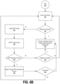
- FIG. 6 A will be described in conjunction with FIG. 6 B , which illustrates an example method or set of operations that may be performed by sensor 210 to adaptively select a connectivity mechanism for provisioning sensor 210 .
- sensor 210 may include a hardware processor 212 and a machine-readable storage medium 214 .
- Hardware processor 212 may be one or more central processing units (CPUs), semiconductor-based microprocessors, and/or other hardware devices, such as circuits, suitable for retrieval and execution of instructions stored in machine-readable storage medium, 214 .
- a machine-readable storage medium, such as machine-readable storage medium 214 may be any electronic, magnetic, optical, or other physical storage device that contains or stores executable instructions.
- machine-readable storage medium 214 may be, for example, Random Access Memory (RAM), non-volatile RAM (NVRAM), an Electrically Erasable Programmable Read-Only Memory (EEPROM), a storage device, an optical disc, and the like.
- RAM Random Access Memory
- NVRAM non-volatile RAM
- EEPROM Electrically Erasable Programmable Read-Only Memory
- machine-readable storage medium 214 may be a non-transitory storage medium, where the term “non-transitory” does not encompass transitory propagating signals.
- Machine-readable storage medium 214 may be encoded with executable instructions for performing the aforementioned adaptive selection of a connectivity mechanism in the form of adaptive selection/connection logic or algorithm 216 .
- Sensor 210 may further comprise one or more transmitters or receivers for transmitting/receiving information or data, referred to in FIG. 6 A as transceiver 218 .
- Devices, such as sensor 210 may support various connectivity mechanisms, including wireless connection mechanisms.
- transceiver 218 operatively connected to transceiver 218 are one or more antennas for communicating vis-à-vis such connectivity mechanisms, e.g., antennas 218 A, 218 B, and 218 C.
- antennas 218 A, 218 B, or 218 C may support a particular wireless connectivity mechanism, while an interface 218 D may support wired connectivity.
- interface 218 D may comprise a wired Ethernet port.
- FIG. 6 B illustrates a method for adaptively selecting a connectivity mechanism over which onboarding and configuration of a device, such as sensor 210 , may occur.
- a device such as a sensor, leveraging DPP-over Wi-Fi®.
- a sensor such as sensor 210
- embodiments may select an appropriate or preferred connectivity mechanism leveraging any available connection mechanism.
- a device such as sensor 210 may be powered on/booted up at operation 250 .
- a check is performed to determine if the device has Ethernet capability. That is, and for example, a check may be performed by adaptive selection/connection component 216 ( FIG. 6 A ) to determine whether a communications connection over interface 218 D (which may be an Ethernet interface) has been established at operation 254 .
- the device connects to a backend network insight system, e.g., backend network insight system 220 using the Ethernet connection that was established.
- a backend network insight system e.g., backend network insight system 220 using the Ethernet connection that was established.
- the backend network insight system 220 provides configurations to devices, such as sensor 210 . That is, sensor 210 may access or download one or more configurations or configuration files that may be the basis for monitoring or testing network 200 . Accordingly, at operation 264 , the device at issue can connect to the backend network insight system 220 , and download any requisite configuration(s).
- a DPP provisioning and onboarding routine can be invoked at operation 256 .
- DPP-over Wi-Fi® may be used to effectuate a connection, such as an 802.11 communications connection, to the backend network insight system.
- the device may scan for any available DPP Wi-Fi® network(s). For example, the device may begin transmitting DPP presence announcements If picked up by an AP, the AP, having sensor device and bootstrapping information from a cloud-based configurator, can authenticate the device.
- the device can iterate through/establish connections through the DPP network(s) vis-à-vis the aforementioned AP at operation 266 .
- a connection can be established between the device and the backend network insight system to allow configurations to be passed on to the device for use with monitoring or testing of the network, applications running on the network, etc. That is, the method returns to operation 264 for the device to connect to the backend network insight system. If for some reason, a connection cannot be established at this point, the method returns to operation 252 , where the method of adaptive selection of connectivity mechanisms can begin again.
- the device can attempt to connect over a cellular connection. That is, at operation 262 , a check can be performed to determine if the device is connected to or can connect to a cellular network over which configuration information from the backend network insight system can be obtained. If so, again, at operation 268 , a connection can be established between the device and the backend network insight system to allow configurations to be passed on to the device for use with monitoring or testing of the network, applications running on the network, etc.
- FIG. 7 illustrates an example of sensor 210 communicating monitoring/test information or data to backend network insight dashboard system 226 on or in which a dashboard 226 A may be implemented or presented, e.g., to a user.
- the owner or administrator of network 200 may have an interest in determining the current status/state of network 200 , applications running thereon, etc.
- sensor 210 may then connect to backend network insight system 220 via device gateway 222 .
- sensor 210 may transmit monitoring or testing information/data 211 to backend network insight system 220 .
- the API gateway 224 of backend network insight system 220 may then forward or transmit the monitoring or testing information/data 225 to dashboard system 226 .
- the monitoring or testing information/data may be presented to a user via dashboard 226 A of dashboard system 226 (which may be a computer, workstation, laptop, or other computing/processing system or component capable of receiving and presenting such information/data).
- the DPP protocol does not define how a configurator (such as an AP) can obtain bootstrapping info (public key and other information) from an enrollee (such as a sensor). Rather, the DPP protocol relies on out-of-band ( 00 B) mechanisms such as scanning a QR code, NFC tapping, etc. In contrast, embodiments of the disclosed technology can define or provide a new mechanism with which to push device bootstrapping information to a cloud-based configurator from a backend network insight system.
- some embodiments may include the selection of a connectivity mechanism for provisioning a device, such as a sensor.
- a connectivity mechanism for provisioning a device such as a sensor.
- sensors may be provisioned using DPP-over Wi-Fi®, Ethernet, Bluetooth® Low Energy, or cellular, based on deployment.
- DPP allows for the onboarding of any client device that matches the relevant key pair.
- An AP will provision the 802.11 network credentials into the device, and the device can initiate a connection to the network.
- an authorization mechanism for example, based on customer ID
- Embodiments of the disclosed technology can increase the security aspects of DPP by adding a cloud-based mechanism where only the authorized devices are onboarded to a network.
- FIG. 8 depicts a block diagram of an example computer system 800 in which various of the embodiments described herein may be implemented.
- Computer system 800 may be an embodiment of sensor 210 , AP 240 , as well as one or more components of network 200 , e.g., backend network insight system 220 , frontend network insight dashboard system 226 , and so on.
- the computer system 800 includes a bus 802 or other communication mechanism for communicating information, one or more hardware processors 804 coupled with bus 802 for processing information.
- Hardware processor(s) 804 may be, for example, one or more general purpose microprocessors.
- the computer system 800 also includes a main memory 806 , such as a random access memory (RAM), cache and/or other dynamic storage devices, coupled to bus 802 for storing information and instructions to be executed by processor 804 .
- Main memory 806 also may be used for storing temporary variables or other intermediate information during execution of instructions to be executed by processor 804 .
- Such instructions when stored in storage media accessible to processor 804 , render computer system 800 into a special-purpose machine that is customized to perform the operations specified in the instructions.
- the computer system 800 further includes a read only memory (ROM) 808 or other static storage device coupled to bus 802 for storing static information and instructions for processor 804 .
- ROM read only memory
- a storage device 810 such as a magnetic disk, optical disk, or USB thumb drive (Flash drive), etc., is provided and coupled to bus 802 for storing information and instructions.
- the computer system 800 may be coupled via bus 802 to a display 812 , such as a liquid crystal display (LCD) (or touch screen), for displaying information to a computer user.
- a display 812 such as a liquid crystal display (LCD) (or touch screen)
- An input device 814 is coupled to bus 802 for communicating information and command selections to processor 804 .
- cursor control 816 is Another type of user input device
- cursor control 816 such as a mouse, a trackball, or cursor direction keys for communicating direction information and command selections to processor 804 and for controlling cursor movement on display 812 .
- the same direction information and command selections as cursor control may be implemented via receiving touches on a touch screen without a cursor.
- the computing system 800 may include a user interface module to implement a GUI that may be stored in a mass storage device as executable software codes that are executed by the computing device(s).
- This and other modules may include, by way of example, components, such as software components, object-oriented software components, class components and task components, processes, functions, attributes, procedures, subroutines, segments of program code, drivers, firmware, microcode, circuitry, data, databases, data structures, tables, arrays, and variables.
- the word “component,” “engine,” “system,” “database,” data store,” and the like, as used herein, can refer to logic embodied in hardware or firmware, or to a collection of software instructions, possibly having entry and exit points, written in a programming language, such as, for example, Java, C or C++.
- a software component may be compiled and linked into an executable program, installed in a dynamic link library, or may be written in an interpreted programming language such as, for example, BASIC, Perl, or Python. It will be appreciated that software components may be callable from other components or from themselves, and/or may be invoked in response to detected events or interrupts.
- Software components configured for execution on computing devices may be provided on a computer readable medium, such as a compact disc, digital video disc, flash drive, magnetic disc, or any other tangible medium, or as a digital download (and may be originally stored in a compressed or installable format that requires installation, decompression or decryption prior to execution).
- a computer readable medium such as a compact disc, digital video disc, flash drive, magnetic disc, or any other tangible medium, or as a digital download (and may be originally stored in a compressed or installable format that requires installation, decompression or decryption prior to execution).
- Such software code may be stored, partially or fully, on a memory device of the executing computing device, for execution by the computing device.
- Software instructions may be embedded in firmware, such as an EPROM.
- hardware components may be comprised of connected logic units, such as gates and flip-flops, and/or may be comprised of programmable units, such as programmable gate arrays or processors.
- the computer system 800 may implement the techniques described herein using customized hard-wired logic, one or more ASICs or FPGAs, firmware and/or program logic which in combination with the computer system causes or programs computer system 800 to be a special-purpose machine. According to one embodiment, the techniques herein are performed by computer system 800 in response to processor(s) 804 executing one or more sequences of one or more instructions contained in main memory 806 . Such instructions may be read into main memory 806 from another storage medium, such as storage device 810 . Execution of the sequences of instructions contained in main memory 806 causes processor(s) 804 to perform the process steps described herein. In alternative embodiments, hard-wired circuitry may be used in place of or in combination with software instructions.
- non-transitory media refers to any media that store data and/or instructions that cause a machine to operate in a specific fashion. Such non-transitory media may comprise non-volatile media and/or volatile media.
- Non-volatile media includes, for example, optical or magnetic disks, such as storage device 810 .
- Volatile media includes dynamic memory, such as main memory 806 .
- non-transitory media include, for example, a floppy disk, a flexible disk, hard disk, solid state drive, magnetic tape, or any other magnetic data storage medium, a CD-ROM, any other optical data storage medium, any physical medium with patterns of holes, a RAM, a PROM, and EPROM, a FLASH-EPROM, NVRAM, any other memory chip or cartridge, and networked versions of the same.
- Non-transitory media is distinct from but may be used in conjunction with transmission media.
- Transmission media participates in transferring information between non-transitory media.
- transmission media includes coaxial cables, copper wire and fiber optics, including the wires that comprise bus 802 .
- transmission media can also take the form of acoustic or light waves, such as those generated during radio-wave and infra-red data communications.
- the computer system 800 also includes a communication interface 818 coupled to bus 802 .
- Network interface 818 provides a two-way data communication coupling to one or more network links that are connected to one or more local networks.
- communication interface 818 may be an integrated services digital network (ISDN) card, cable modem, satellite modem, or a modem to provide a data communication connection to a corresponding type of telephone line.
- ISDN integrated services digital network
- network interface 818 may be a local area network (LAN) card to provide a data communication connection to a compatible LAN (or WAN component to communicated with a WAN).
- LAN local area network
- Wireless links may also be implemented.
- network interface 818 sends and receives electrical, electromagnetic or optical signals that carry digital data streams representing various types of information.
- a network link typically provides data communication through one or more networks to other data devices.
- a network link may provide a connection through local network to a host computer or to data equipment operated by an Internet Service Provider (ISP).
- ISP Internet Service Provider
- the ISP in turn provides data communication services through the world wide packet data communication network now commonly referred to as the “Internet.”
- Internet Internet
- Local network and Internet both use electrical, electromagnetic or optical signals that carry digital data streams.
- the signals through the various networks and the signals on network link and through communication interface 818 which carry the digital data to and from computer system 800 , are example forms of transmission media.
- the computer system 800 can send messages and receive data, including program code, through the network(s), network link and communication interface 818 .
- a server might transmit a requested code for an application program through the Internet, the ISP, the local network and the communication interface 818 .
- the received code may be executed by processor 804 as it is received, and/or stored in storage device 810 , or other non-volatile storage for later execution.
- Each of the processes, methods, and algorithms described in the preceding sections may be embodied in, and fully or partially automated by, code components executed by one or more computer systems or computer processors comprising computer hardware.
- the one or more computer systems or computer processors may also operate to support performance of the relevant operations in a “cloud computing” environment or as a “software as a service” (SaaS).
- SaaS software as a service
- the processes and algorithms may be implemented partially or wholly in application-specific circuitry.
- the various features and processes described above may be used independently of one another, or may be combined in various ways. Different combinations and sub-combinations are intended to fall within the scope of this disclosure, and certain method or process blocks may be omitted in some implementations.
Landscapes
- Engineering & Computer Science (AREA)
- Computer Networks & Wireless Communication (AREA)
- Signal Processing (AREA)
- Power Engineering (AREA)
- Computer Hardware Design (AREA)
- Computer Security & Cryptography (AREA)
- Computing Systems (AREA)
- General Engineering & Computer Science (AREA)
- Automation & Control Theory (AREA)
- Mobile Radio Communication Systems (AREA)
Abstract
Description
Claims (18)
Priority Applications (1)
| Application Number | Priority Date | Filing Date | Title |
|---|---|---|---|
| US17/729,487 US12009979B2 (en) | 2022-04-26 | 2022-04-26 | Secure and adaptive mechanism to provision zero- touch network devices |
Applications Claiming Priority (1)
| Application Number | Priority Date | Filing Date | Title |
|---|---|---|---|
| US17/729,487 US12009979B2 (en) | 2022-04-26 | 2022-04-26 | Secure and adaptive mechanism to provision zero- touch network devices |
Publications (2)
| Publication Number | Publication Date |
|---|---|
| US20230344715A1 US20230344715A1 (en) | 2023-10-26 |
| US12009979B2 true US12009979B2 (en) | 2024-06-11 |
Family
ID=88414941
Family Applications (1)
| Application Number | Title | Priority Date | Filing Date |
|---|---|---|---|
| US17/729,487 Active 2042-04-30 US12009979B2 (en) | 2022-04-26 | 2022-04-26 | Secure and adaptive mechanism to provision zero- touch network devices |
Country Status (1)
| Country | Link |
|---|---|
| US (1) | US12009979B2 (en) |
Citations (8)
| Publication number | Priority date | Publication date | Assignee | Title |
|---|---|---|---|---|
| US20160323689A1 (en) * | 2015-04-30 | 2016-11-03 | Lantronix, Inc. | Zero-touch wi-fi |
| US20170171196A1 (en) * | 2015-12-14 | 2017-06-15 | Afero, Inc. | System and method for secure internet of things (iot) device provisioning |
| US20180116004A1 (en) | 2016-10-21 | 2018-04-26 | Afero, Inc. | Internet of things (iot) system and method for selecting a secondary communication channel |
| US20180375665A1 (en) | 2017-06-21 | 2018-12-27 | Microsoft Technology Licensing, Llc | Device provisioning |
| US20190116087A1 (en) * | 2017-10-13 | 2019-04-18 | BLX.io LLC | CONFIGURATION FOR IoT DEVICE SETUP |
| US10447683B1 (en) * | 2016-11-17 | 2019-10-15 | Amazon Technologies, Inc. | Zero-touch provisioning of IOT devices with multi-factor authentication |
| US11558187B2 (en) * | 2017-08-18 | 2023-01-17 | Samsung Electronics Co., Ltd. | Method and an apparatus for onboarding in an IoT network |
| US11658867B1 (en) * | 2022-02-26 | 2023-05-23 | Cisco Technology, Inc. | Zero-touch deployment (ZTD) with adaptive network control policies |
-
2022
- 2022-04-26 US US17/729,487 patent/US12009979B2/en active Active
Patent Citations (8)
| Publication number | Priority date | Publication date | Assignee | Title |
|---|---|---|---|---|
| US20160323689A1 (en) * | 2015-04-30 | 2016-11-03 | Lantronix, Inc. | Zero-touch wi-fi |
| US20170171196A1 (en) * | 2015-12-14 | 2017-06-15 | Afero, Inc. | System and method for secure internet of things (iot) device provisioning |
| US20180116004A1 (en) | 2016-10-21 | 2018-04-26 | Afero, Inc. | Internet of things (iot) system and method for selecting a secondary communication channel |
| US10447683B1 (en) * | 2016-11-17 | 2019-10-15 | Amazon Technologies, Inc. | Zero-touch provisioning of IOT devices with multi-factor authentication |
| US20180375665A1 (en) | 2017-06-21 | 2018-12-27 | Microsoft Technology Licensing, Llc | Device provisioning |
| US11558187B2 (en) * | 2017-08-18 | 2023-01-17 | Samsung Electronics Co., Ltd. | Method and an apparatus for onboarding in an IoT network |
| US20190116087A1 (en) * | 2017-10-13 | 2019-04-18 | BLX.io LLC | CONFIGURATION FOR IoT DEVICE SETUP |
| US11658867B1 (en) * | 2022-02-26 | 2023-05-23 | Cisco Technology, Inc. | Zero-touch deployment (ZTD) with adaptive network control policies |
Also Published As
| Publication number | Publication date |
|---|---|
| US20230344715A1 (en) | 2023-10-26 |
Similar Documents
| Publication | Publication Date | Title |
|---|---|---|
| US11546755B2 (en) | Centralized configurator server for DPP provisioning of enrollees in a network | |
| US20240276214A1 (en) | Device Default Wifi Credentials for Simplified and Secure Configuration of Networked Transducers | |
| CN110770695B (en) | Internet of things (IOT) device management | |
| US20200226258A1 (en) | Hosted device provisioning protocol with servers and a networked initiator | |
| US20190356482A1 (en) | A hosted dynamic provisioning protocol with servers and a networked responder | |
| US10958664B2 (en) | Method of performing integrity verification between client and server and encryption security protocol-based communication method of supporting integrity verification between client and server | |
| US8392712B1 (en) | System and method for provisioning a unique device credential | |
| US20200259667A1 (en) | Distributed management system for remote devices and methods thereof | |
| WO2019153701A1 (en) | Method and apparatus for obtaining device identification | |
| US10009359B2 (en) | System, apparatus and method for transferring ownership of a device from manufacturer to user using an embedded resource | |
| US20190268764A1 (en) | Data transmission method, apparatus, and system | |
| EP3065334A1 (en) | Key configuration method, system and apparatus | |
| US12095770B2 (en) | Connecting internet of thing (IoT) devices to a wireless network | |
| EP4231680A1 (en) | Identity authentication system, method and apparatus, device, and computer readable storage medium | |
| US10924480B2 (en) | Extended trust for onboarding | |
| WO2019221905A1 (en) | Secure methods and systems for identifying bluetooth connected devices with installed application | |
| US20200274707A1 (en) | Server for and method of secure device registration | |
| KR20190034048A (en) | Server registration method of client using encryption security protocol-based communication and integrity verification method between client and server using the same | |
| US20200274719A1 (en) | Generating trust for devices | |
| US12009979B2 (en) | Secure and adaptive mechanism to provision zero- touch network devices | |
| Gao et al. | SecT: A lightweight secure thing-centered IoT communication system | |
| US8949598B2 (en) | Method and apparatus for secured embedded device communication | |
| US20230171097A1 (en) | Securely changing cryptographic strength during reconfiguration | |
| US20220200984A1 (en) | Provisioning data on a device | |
| US20220256349A1 (en) | Provision of Application Level Identity |
Legal Events
| Date | Code | Title | Description |
|---|---|---|---|
| AS | Assignment |
Owner name: HEWLETT PACKARD ENTERPRISE DEVELOPMENT LP, TEXAS Free format text: ASSIGNMENT OF ASSIGNORS INTEREST;ASSIGNORS:SIRAJ, MOHD SHAHNAWAZ;BAHAL, RAHUL;KONATH, KANNAN;AND OTHERS;SIGNING DATES FROM 20220420 TO 20220425;REEL/FRAME:059733/0872 |
|
| FEPP | Fee payment procedure |
Free format text: ENTITY STATUS SET TO UNDISCOUNTED (ORIGINAL EVENT CODE: BIG.); ENTITY STATUS OF PATENT OWNER: LARGE ENTITY |
|
| STPP | Information on status: patent application and granting procedure in general |
Free format text: NON FINAL ACTION MAILED |
|
| STPP | Information on status: patent application and granting procedure in general |
Free format text: RESPONSE TO NON-FINAL OFFICE ACTION ENTERED AND FORWARDED TO EXAMINER |
|
| STPP | Information on status: patent application and granting procedure in general |
Free format text: NOTICE OF ALLOWANCE MAILED -- APPLICATION RECEIVED IN OFFICE OF PUBLICATIONS |
|
| STPP | Information on status: patent application and granting procedure in general |
Free format text: AWAITING TC RESP., ISSUE FEE NOT PAID |
|
| STPP | Information on status: patent application and granting procedure in general |
Free format text: NOTICE OF ALLOWANCE MAILED -- APPLICATION RECEIVED IN OFFICE OF PUBLICATIONS |
|
| STPP | Information on status: patent application and granting procedure in general |
Free format text: PUBLICATIONS -- ISSUE FEE PAYMENT VERIFIED |
|
| STPP | Information on status: patent application and granting procedure in general |
Free format text: AWAITING TC RESP, ISSUE FEE PAYMENT VERIFIED |
|
| STPP | Information on status: patent application and granting procedure in general |
Free format text: PUBLICATIONS -- ISSUE FEE PAYMENT VERIFIED |
|
| STCF | Information on status: patent grant |
Free format text: PATENTED CASE |