US12007202B2 - Mounting device for weapon accessories - Google Patents
Mounting device for weapon accessories Download PDFInfo
- Publication number
- US12007202B2 US12007202B2 US17/995,674 US202117995674A US12007202B2 US 12007202 B2 US12007202 B2 US 12007202B2 US 202117995674 A US202117995674 A US 202117995674A US 12007202 B2 US12007202 B2 US 12007202B2
- Authority
- US
- United States
- Prior art keywords
- locking
- mounting device
- spindle
- protrusion
- recess
- Prior art date
- Legal status (The legal status is an assumption and is not a legal conclusion. Google has not performed a legal analysis and makes no representation as to the accuracy of the status listed.)
- Active, expires
Links
Images



Classifications
-
- F—MECHANICAL ENGINEERING; LIGHTING; HEATING; WEAPONS; BLASTING
- F41—WEAPONS
- F41G—WEAPON SIGHTS; AIMING
- F41G11/00—Details of sighting or aiming apparatus; Accessories
- F41G11/001—Means for mounting tubular or beam shaped sighting or aiming devices on firearms
- F41G11/003—Mountings with a dove tail element, e.g. "Picatinny rail systems"
Definitions
- the present disclosure relates to a mounting device for the temporary coupling of accessories to a firearm and to accessories having such an integrally formed mounting device.
- Accessories for firearms in the context of this application are understood to mean any piece of equipment that is to be temporarily connected to the weapon and also to be detached. These can be laser sights, illuminated dot reticles, range finders, or light sources of any kind. Telescopic sights, IR aiming devices and the like are also to be considered for the purposes of the present disclosure. In principle, however, such a mounting device is also conceivable for mounting on objects other than firearms, such as vehicles, and should therefore be also read in this sense by a person skilled in the art.
- U.S. Pat. No. 9,857,142 B2 proposes an alternative mounting device which can be “swiveled” onto a Picatinny rail and fixed to a recess provided there by means of an extension.
- This mounting device has a further Picatinny rail for fixing an accessory on the outside.
- U.S. Pat. No. 9,551,550 B2 describes a mounting device integrated into a housing of an accessory part in which two wedge elements can be moved toward one another by means of a screw connection. As a result, the wedge elements slide along inclined guides in the housing, and a crosspiece is brought into engagement with a recess in a guide element of the weapon.
- US2011/0061283 A1 discloses the use of a swiveling part which is oriented transvers to the barrel axis and under the load of a spring, in an embodiment turned by 90° and symmetrical to the median plane of the weapon; in both embodiments, the very blocking element is held by force only and therefore, in view of the dynamic forces, not fixed reliable.
- U.S. Pat. No. 6,185,854 B1 discloses a similar device, using a leaf spring, which is in danger to get lost, and, as may be seen in FIG. 6 , is hardly in a position to achieve reproducible positions, since a ramp is provided in order to make the mounting easier and to avoid the loss, but does not achieve a robust mounting.
- US2016/0146572 A1 discloses the use of a spring-loaded screwing device, which may be used by hand; the spring should avoid unfastening, which, in view of the dynamic forces makes it necessary to fasten the device remarkably, which is, despite the size of the knob of the screw hardly possible. Additionally, there is the problem of contamination on the one hand and jamming of the screw mechanism on the other hand.
- the object of the present disclosure is to overcome the known aforementioned disadvantages in the prior art and to provide a mounting device which is compact and space-saving.
- a mounting device leads to the achievement of the aforementioned objects.
- the present disclosure is directed to mounting devices for the temporary coupling of accessories to a firearm, and accessories including such a mounting device.
- the mounting device includes a device housing having guides configured to interact with guide elements of the firearm, a spring; at least one bearing knob; at least one locking spindle having a spindle axis, the locking spindle being configured to interact with the bearing knob and the recess; the locking spindle having a first end, a center part, and a second end; where the first end includes a selector knob with a resting protrusion, the center part has at least one locking protrusion formed in a spatial direction normal to the spindle axis, and the second end includes a connection piece; and the locking spindle is disposed in the device housing so that the locking spindle is rotatably and/or longitudinally displaceable.
- the mounting device is configured so that it can be placed in an open position by a displacement of at least the resting protrusion of the selector knob along the spindle axis, bringing the resting protrusion out of engagement with a detent formed on a side of the device housing, where the detent is complementary in shape to the resting protrusion, thereby enabling a rotation of the locking spindle; the rotation of the locking spindle can disengage the locking protrusion from the recess, thereby enabling a displacement of the mounting device along the guide elements; and the mounting device can be mounted on the firearm in a locking position by bringing the locking protrusion into engagement with the recess and engaging at least the resting protrusion of the selector knob partially or completely with the detent, thereby locking the mounting device in place.
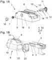
- FIG. 1 A is a simplified exploded view of a mounting device according to the present disclosure
- FIG. 1 B shows a mounting device according to FIG. 1 A mounted on an accessory.
- FIG. 2 A is a schematic oblique view of an illustrative mounting device mounted on a receiver of a pistol;
- FIG. 2 B shows an accessory with an integrally formed mounting device according to the present disclosure mounted on the receiver of a rifle.
- FIG. 3 A is a schematic view of a mounting device according to the present disclosure in the unlocked position;
- FIG. 3 B shows the mounting device according to FIG. 3 A in the locking position.
- FIGS. 4 A- 4 C depict a mounting device according to the present disclosure.
- FIG. 4 A is a schematic view of the mounting device with the locking spindle shown in various positions;
- FIG. 4 B shows corresponding cross-section views along B-B′ of FIG. 4 A ;
- FIG. 4 C shows a vertical sectional view along C-C′ of FIG. 2 A .
- FIGS. 5 A- 5 C depict a mounting device according to the present disclosure.
- FIG. 5 A is a schematic view of the mounting device with the locking spindle shown in various positions;
- FIG. 5 B shows corresponding cross-section views along B-B′ of FIG. 5 A ;
- FIG. 5 C shows a vertical sectional view along C-C′ of FIG. 2 A .
- FIGS. 7 A- 7 C depict a mounting device according to the present disclosure.
- FIG. 7 A is a schematic view of the mounting device with the locking spindle shown in various positions;
- FIG. 7 B shows corresponding cross-section views along B-B′ of FIG. 7 A ;
- FIG. 7 C shows a vertical sectional view along D-D′ of FIG. 2 B .
- FIGS. 8 A and 8 B schematically show an illustrative mounting device according to the present disclosure having two locking spindles and a coupling device in two oblique views.
- FIGS. 10 A- 10 C depict a mounting device according to the present disclosure having two locking spindles.
- FIG. 10 A is a schematic view of the mounting device with the locking spindles shown in various positions;
- FIG. 10 B shows corresponding cross-section views along B-B′ of FIG. 10 A ;
- FIG. 10 C shows the two locking spindles having opposing directions of rotation.
- the housing of the mounting device has guides which allow longitudinal guidance, especially laterally, along guide elements of a firearm.
- these guides also offer an additional support surface in the vertical direction, that is to say “upward” and/or “downward” when viewed from the weapon, via a profile that is complementary in shape to the guide element. This can also be achieved with a T-profile, as well as preferably when Picatinny rails are used.
- the guide is preferably designed as guide rails, wherein these guide rails do not have to be continuous in the longitudinal direction.
- turning the locking protrusion makes it possible for the mounting device—and thus the accessory—to contact and, where necessary, also clamp on the weapon.
- a person skilled in the art can achieve a very quick and easy-to-perform coupling of the accessories on the weapon.
- the relatively compact design is helped by the small number of components and their interaction according to the present disclosure. This also allows a cost-optimized production of high-quality components with low weight.
- a further advantage of the mounting devices of the present disclosure is the possibility of having the locking position assumed largely automatically by the spring pretensioning. This “self-locking effect” benefits the user during routine assembly after a change of accessories, but especially in stressful situations.
- the present disclosure extends to any type of accessory, such as a tactical light, a red dot sight, or the like, which have such a mounting device integrated.
- the disclosed mounting device can also be used as an adapter for accessory parts with an alternative mounting device, or as a spacer. This can be used, for example, when a telescopic sight is mounted on an adapter, which can be mounted on the weapon relatively quickly and with repeatability by means of the proposed mounting device.
- FIG. 1 schematically shows a mounting device 1 ( FIG. 1 A ), as well as the mounting device 1 mounted on an accessory 8 ( FIG. 1 B ) in an exploded view; the direction of the running axis is inserted parallel to the x-direction of the drawn coordinate system.
- the guide 6 also runs in this direction.
- the locking spindle 10 can be introduced into the device housing 5 along the spindle axis 9 and can be connected to the bearing knob 16 on the connection piece 14 .
- the connection piece 14 can be designed with the bearing knob 16 , for example, as a detachable screw connection or plug-in connection, or also as a non-detachable plug-in connection.
- the locking spindle 10 is preferably secured against unintentional loosening on the connection piece 14 by means of a spring ring or, as can be seen in FIG. 1 A , by means of a pin or spring pin.
- An equally suitable, albeit non-detachable, plug-in connection is indicated by way of example in FIG. 9 B .
- the spring 7 serves to pretension the locking spindle 10 in the installed state in the direction of the bearing knob 16 and thus pulls the selector knob 11 essentially in the direction of the locking position.
- the spring 7 is preferably arranged between the device housing 5 and the bearing knob 16 , although alternative arrangements are also conceivable.
- the spring 7 can be designed as a coil spring, preferably as a conical spring.
- the bearing knob 16 can under certain circumstances be designed to be hollow in order to accommodate the spring 7 and thus save space.
- the selected illustrations all have mounting devices 1 designed to be particularly space-saving. It is advantageous that the spring 7 , as well as parts of the bearing knob 16 ; are at least partially accommodated within the device housing 5 by having a bearing recess 18 . Opposite this, a selector recess 19 ( FIG. 5 B ) for at least partial accommodation of the selector knob 11 can be formed on the device housing 5 . As a result of these measures, the bearing and/or selector knobs 11 can be countersunk in a targeted manner relative to the surroundings and accordingly reduce the overall dimensions of the mounting device 1 or the firearm.
- the locking spindle 10 has a plurality of portions and can be constructed in several parts or, preferably, in one part.
- a selector knob 11 which has a resting protrusion 12 in at least one spatial direction is formed at the first end.
- a plurality of latching projections can also be formed, or for example a star-shaped selector knob 11 .
- the locking spindle 10 has the connection piece 14 described above at the second end.
- a center portion or center part 13 is formed, from which at least one locking protrusion 15 is formed projecting in at least one spatial direction.
- the locking protrusion 15 is formed normal to the direction of the resting protrusion 12 when viewed in the circumferential direction of the axis of the locking spindle.
- the selector knob 11 can under certain circumstances have a plurality of steps toward the center part 13 in order to achieve an improved support or bracing in the selector recess 19 ( FIG. 5 B ).
- the device housing 5 has one or more openings which run normal to the guide 6 in the transverse direction, that is to say the y-direction in the selected illustration.
- the guide 6 is designed to interact with the guide elements 3 of a firearm or another object. This can be seen very clearly from FIG. 1 B , in which the front portion of a receiver 2 and a tactical light 8 with a mounting device 1 can be seen.
- the receiver 2 has guide elements 3 with a recess 4 on its underside.
- the accessory 8 can be pushed onto the receiver 2 by longitudinally shifting the mounting device 1 along the dashed lines and fastened by turning the selector knob 11 , as will be explained in more detail later.
- the mounting device 1 has a plurality of openings (see the corners of the device housing 5 ) in order to be screwed to an accessory 8 , for example.
- FIG. 2 schematic representations of assembled mounting devices 1 can be seen, the mounting device 1 being screwed to the accessory 8 in FIG. 2 A or being formed integrally with the accessory 8 in FIG. 2 B .
- a tactical light for example, is attached to a receiver 2
- a red dot or luminous point sight is shown as an accessory 8 in FIG. 2 B .
- the mounting device 1 is also very suitable for guide elements 3 of long guns (e.g. rifles).
- the illustration corresponds to a simplified section through a fore-end profile of an automatic rifle and, as the guide element 3 , represents a greatly simplified guide rail with a plurality of recesses 4 .
- Guides 6 are formed in order to ensure a lateral support of the mounting device 1 on the firearm.
- the guides 6 are matched to the guide elements 3 in accordance with their cross-sectional shape and are thus designed to be complementary in shape. It is left to a person skilled in the art to design the shape and position tolerances accordingly in order to achieve the desired fit; this is also known for guides in the prior art and therefore does not pose a problem with knowledge of the present disclosure.
- FIG. 3 is a schematic representation of an exemplary mounting device 1 in a side view (left row of images) and in a rear view (right row of images).
- the open position can be seen in FIG. 3 A —that is, for the longitudinal adjustment of the mounting device 1 along the guides 6 —and the locking position in FIG. 3 B .
- the selector knob 11 is pushed out of the device housing 5 in the y-direction by actuation of the bearing knob 16 and the resting protrusion 12 is rotated downward, whereby the locking protrusion 15 is “pivoted in” within a recess 27 of the device housing 5 .
- the locking protrusion 15 is brought out of engagement with the recess 4 of a receiver 2 or another object and in this position no longer protrudes or only slightly protrudes over the surface of the device housing 5 , as shown particularly well in FIG. 3 A on the right (or else FIG. 11 A ).
- This makes possible a longitudinal displacement of the mounting device 1 along guide elements 3 ( FIG. 1 B ).
- the locking spindle 10 in the installed state is therefore mounted so that it can be displaced and/or rotated within limits inside the device housing 5 .
- the locking protrusion 15 is also “pivoted out” of the recess 27 (see, for example, FIGS. 4 - 7 , 11 ) and can prevent a longitudinal displacement of the mounting device 1 by engaging in a corresponding recess 4 of the guide element 3 .
- the selector recess 19 and/or the detent 17 are preferably designed complementary in shape to the selector knob 11 or the resting protrusion 12 . This makes it possible for the selector knob 11 and/or the resting protrusion 12 to be at least partially received in the device housing 5 and thus to protrude just a little or not at all from its surface.
- the proposed construction makes it possible for accidental locking or unlocking to be relatively unlikely.
- the locked state is clearly visible and can even be felt in the dark, as can be determined relatively easily by the protruding bearing knob 16 or the latched resting protrusion 12 .
- FIGS. 4 - 7 different embodiments can be seen which primarily show the possibilities of different locking protrusions 15 .
- FIGS. 4 - 7 are each structured analogously, in that the installation process can be seen from right to left and the locking status can be seen in the left column.
- each top view is shown in the z direction.
- sectional views B-B′ of the spindle axis 9 corresponding to the plan views can be seen.
- Sectional views C-C′ and D-D′ through the center plane of the mounting device 1 on the guide element 3 of a firearm are shown schematically in the respective lower image section (Fig. XXC), as becomes clear when looking at FIG. 2 .
- FIGS. 4 C and 5 D correspond to FIG. 2 A and FIGS. 6 C and 7 C with FIG. 2 B .
- FIG. 4 A possible embodiment is shown in FIG. 4 , the locking protrusion 15 in the center part 13 being formed on one side of the locking spindle 10 .
- the locking spindle 10 is inserted into the device housing 5 , as can be seen very clearly in section in the illustrations below in FIG. 4 B .
- the locking protrusion 15 can be inserted in such a way that it is “pivoted in” within the recess 27 . If the locking spindle 10 is rotated into the working position, that is to say the locked state (see FIG. 4 A ), the resting protrusion 12 can engage in the detent 17 as described above, and the locking protrusion 15 is “up,” i.e.
- the accessory 8 is supported by the accessory housing 23 with respect to the receiver 2 and is thus attached to the firearm.
- the mounting device 1 can thus be supported in the longitudinal direction of the guide 6 with respect to a receiver 2 and can thus be mounted without play on a firearm.
- the mounting device 1 can also be designed in such a way that the support is accomplished via the guide element 3 by engaging in one or more recesses, as will be explained later.
- a person skilled in the art can also minimize the clearance in the vertical direction by suitable adaptation of the guide 6 in relation to the guide elements 3 of a firearm.
- FIG. 4 Another possible embodiment can also be seen in FIG. 4 and particularly clearly in FIG. 6 , according to which at least one locking protrusion 15 has a cantilever 21 in the direction of the bearing knob 16 .
- This cantilever 21 serves, in the locking position, to engage in a secondary locking recess 20 arranged parallel to the spindle axis 9 on the device housing 5 .
- the cantilever 21 additionally supports the locking spindle 10 in the locking state within the device housing 5 , after which an improved load transfer and relief of the bearing points of the locking spindle 10 can be achieved, as can be seen particularly well in FIG. 6 B .
- FIG. 5 shows a further possible embodiment of a locking spindle 10 with locking protrusions 15 protruding on both sides.
- the description of FIGS. 4 a and b can be applied mutatis mutandis.
- the two-sided design of the two locking protrusions 15 provides additional support for the locking spindle 10 on the device housing 5 , see FIG. 4 c .
- the “upper” locking protrusion 15 presses in the x direction against the receiver 2 on the sidewall of the recess 4
- the “lower” locking protrusion 15 on the device housing 5 engages the sidewall of the recess 27 . This can relieve the pivot points of the locking spindle 10 within the device housing 5 .
- FIG. 6 Another possible embodiment of a locking spindle 10 is shown schematically in FIG. 6 .
- the description of FIGS. 4 A and 4 B can be applied mutatis mutandis, the locking protrusion 15 formed on one side in the shown example of FIG. 6 being interrupted in the longitudinal direction of the locking spindle 10 or being formed as two locking protrusions 15 spaced apart from one another along the spindle axis 9 .
- This embodiment is particularly suitable for Picatinny rails having a central longitudinal groove, since the two locking protrusions 15 press against the Picatinny rail in the locked state and the longitudinal groove remains free. For this reason, the locking protrusion 15 is also located behind the sectional plane in FIG. 5 C , in the sectional view D-D′; the function is otherwise as described for FIG. 4 C .
- FIG. 7 Another possible embodiment is shown in FIG. 7 , in which the locking protrusion 15 has the cross-sectional shape of a segment of a circle, as can be seen particularly well in FIG. 7 C .
- the installation and the function are carried out in the same way as the aforementioned versions.
- the locking protrusion 15 in at least one further spatial direction, preferably diametrically opposite normal to the spindle axis 9 , as is the case, for example, with the cross-sectional shape of a wave shape or S shape.
- the embodiment with two locking protrusions 15 ( FIG. 5 ) is also to be understood as falling into this category.
- the special embodiment of the locking protrusion 15 in the form of a segment of a circle in FIG. 7 allows an additional support surface on the device housing 5 with suitable coordination with the dimensions of the recesses 4 and thus improves the introduction of force into the receiver 2 , which in turn relieves the bearing points of the device housing 5 , as is also the case with the “two-wing” version in FIG. 5 .
- FIGS. 8 to 11 possible embodiments for mounting devices 1 with two locking spindles 10 are described below, but three or more locking spindles 10 acting in an analogous manner are also conceivable in a mounting device 1 .
- FIGS. 8 A and 8 B are two perspective exploded views of an accessory 8 having a mounted mounting device 1 , shown schematically.
- FIG. 8 A the “right” side with two selector recesses 19 can be seen, in which recesses the selector knobs 11 can be accommodated after the locking spindles 10 have been inserted.
- only one of the selector knobs 11 has a resting protrusion 12 , which is designed to interact with the detent 17 —mutatis mutandis with respect to the preceding description.
- the two locking spindles 10 are, however, designed to be actuated together by only one of the locking spindles 10 being actuated, in practice the one with the resting protrusion 12 .
- the two locking spindles 10 are connected via a coupling device 24 , as can be seen very clearly in conjunction with FIG. 8 B .
- the coupling device 24 comprises two disks 25 and a coupling rod 26 , the disks 25 in the installed state each being assigned to a corresponding locking spindle 10 and being connected thereto, preferably detachably, and the coupling rod 26 connecting the two disks 25 to one another.
- the connection of the disks 25 to the locking spindle 10 can be accomplished, for example, using a plug-in connection with a profile of complementary shape, as can be seen very clearly from FIG. 8 .
- the connection of the disks 25 to the coupling rod 26 is also preferably formed via a plug-in connection, the disks 25 having small connecting projections for the coupling rod 26 , as can be seen in FIG. 8 B .
- FIG. 9 shows a sectional view E-E′ in the z direction from “above” at the level of the spindle axis 9 (FIG. 9 A).
- the locking spindle 10 can be shifted slightly along the spindle axis 9 and rotated about it in the release position.
- FIG. 9 C schematically shows the engagement situation of the locking protrusions 15 in two recesses 4 of a guide element 3 with opposite movement from the rest position into the working position or locking position, as would occur corresponding to the embodiment in FIGS. 8 and 9 A .
- This sectional view is shown analogously to FIGS. 4 C- 7 C on the spindle axis 9 .
- This particular connection of the two locking spindles 10 allows the mounting device 1 to be supported on both sides only on the guide element 3 .
- FIG. 9 B shows a sectional view corresponding to FIG. 9 A , the connection piece 14 being designed as a non-detachable plug-in connection.
- the embodiment is illustrated in the associated detail view.
- the connection piece 14 has a widening and a notch in which a protrusion of the otherwise hollow bearing knob 16 can engage. It is immediately clear to a person skilled in the art that a reverse arrangement can also be implemented.
- a hollow locking spindle 10 or connection piece 14 would be formed therein, for example, and the corresponding bearing knob 16 would have a pin-shaped or mushroom-shaped extension on its inside. It is also clear to a person skilled in the art that these extensions, notches, etc. do not necessarily have to be formed around the entire circumference in order to achieve the desired mounting.
- the coupling device 24 in a suitable manner in order to cause the two locking spindles 10 to rotate in the same direction of rotation. This measure can reduce the local surface pressure of the locking protrusions 15 on the sidewall of the respective recess 4 or on the bearing points of the locking spindles 10 .
- variants of the mounting device of the present disclosure are not shown in which a second detent 17 is provided on the device housing 5 in such a way that the locking spindle 10 can also be pivoted “in the opposite direction.”
- the recess 27 should advantageously be wide enough that the locking protrusion 15 can be pivoted in the “opposite direction.”
- Such an embodiment is particularly advantageous in combination with two locking protrusions 15 , which are formed on both sides of the locking spindle 10 , since the mounting device 1 is used both “forward” and “backward” when viewed in the longitudinal direction of the guide 6 . This largely corresponds to the idea of a “two-sided” design, since the accessory 8 can thus be attached to the firearm in both directions.
- these variants can be combined with all of the embodiments described above.
- FIG. 10 a further embodiment is depicted which shows a mounting device 1 having two independently acting and operable locking spindles 10 ; see in particular FIG. 10 C .
- the directions of rotation of the locking spindles 10 are provided in opposite directions, the function being analogous to the previous description of FIGS. 4 - 7 and a detailed description being dispensed with at this point.
- the support on the guide element 3 is therefore carried out analogously to the sectional view in FIG. 9 C .
- the two resting protrusions 12 are each assigned here a corresponding detent 17 , which are “aligned with one another.” In this way, two identical locking spindles 10 can be used; alternatively, the alignment of the detents 17 in the same direction would also be possible, provided that the alignment and/or number and/or shape of the locking protrusions 15 are designed as desired according to the preceding description.
- FIG. 11 A further possible independent embodiment is shown in FIG. 11 which can be combined with all of the preceding embodiments.
- the device housing 5 has at least one taper 22 for self-centering and locking the resting protrusion 12 in the locking position.
- the taper 22 represents a bevel or else a ramp and is designed to rise outward in such a way that the resting protrusion 12 is guided into the detent 17 when it is rotated into the locking position along the taper 22 .
- a sectional axis F-F′ is drawn in the perspective view in FIG. 11 A and extends “in front of” the spindle axis 9 in the x direction.
- the two representations on the right represent the corresponding cross-sectional views of the plane F-F′ in the x-direction. Especially when viewed together with the locking position in FIG. 11 B , the course and the positioning of the taper 22 or the resting protrusion 12 become clear.
- Such a taper 22 can also or alternatively be provided for self-centering of a cantilever 21 on the locking protrusion 15 in the secondary locking recess 20 .
- a taper 22 can make it easier to snap into the locking position due to the spring pretensioning and, in borderline cases, even cause self-centering or self-locking when the selector knob 11 is released.
- the taper 22 can correspondingly also be formed on the device housing 5 on the inside of the guides 6 .
- the present disclosure also extends to all types of accessories 8 , in particular tactical lights, lasers, red dot or similar sighting devices, as well as silencers which have a mounting device according to any of the preceding embodiments.
- the device housing 5 of the mounting device 1 can be formed integrally with the accessory housing 23 , whereby a particularly high stability and reduced assembly effort can be achieved.
- the present disclosure is not limited to the illustrated and described embodiments, but can be modified and configured in various ways.
- the shown cross-sectional shapes of the aforementioned receiver parts, pins, rails, recesses, etc. can be adapted to the given basic data, and the lengths and the positions with respect to the receiver can also be easily adapted by a person skilled in the art having knowledge of the present disclosure.
- the variants shown and described in the individual embodiments can be combined as required.
- the terms “front,” “rear,” “above,” “below” and so on are used in the generally accepted form and with reference to the object in its usual position of use. This means that in a weapon the muzzle of the barrel is “at the front,” that the slide is moved “backward” by the explosive gas, etc. Transverse to a direction essentially means a direction turned 90° thereto.
- substantially means a deviation of up to 10% of the stated value, if physically possible, both downward and upward, otherwise only in the appropriate direction; in the case of degrees (angle and temperature), this means ⁇ 10°. If there are terms such as “substantially constant” etc., what is meant is the technical possibility of deviation which a person skilled in the art takes as a basis and not the mathematical one.
- a “substantially L-shaped cross-section” comprises two elongated surfaces, which each merge at one end into the end of the other surface, and whose longitudinal extension is arranged at an angle of 45° to 120° to one another.
Landscapes
- Engineering & Computer Science (AREA)
- General Engineering & Computer Science (AREA)
- Pivots And Pivotal Connections (AREA)
- Aiming, Guidance, Guns With A Light Source, Armor, Camouflage, And Targets (AREA)
- Adornments (AREA)
- Stringed Musical Instruments (AREA)
- Toys (AREA)
Applications Claiming Priority (4)
| Application Number | Priority Date | Filing Date | Title |
|---|---|---|---|
| EP20168417 | 2020-04-07 | ||
| EP20168417.2A EP3892954B1 (de) | 2020-04-07 | 2020-04-07 | Befestigungsvorrichtung für waffenzubehör |
| EP20168417.2 | 2020-04-07 | ||
| PCT/EP2021/057901 WO2021204565A1 (de) | 2020-04-07 | 2021-03-26 | Befestigungsvorrichtung für zubehör an einer handfeuerwaffe |
Publications (2)
| Publication Number | Publication Date |
|---|---|
| US20230160664A1 US20230160664A1 (en) | 2023-05-25 |
| US12007202B2 true US12007202B2 (en) | 2024-06-11 |
Family
ID=70227816
Family Applications (1)
| Application Number | Title | Priority Date | Filing Date |
|---|---|---|---|
| US17/995,674 Active 2041-08-06 US12007202B2 (en) | 2020-04-07 | 2021-03-26 | Mounting device for weapon accessories |
Country Status (4)
| Country | Link |
|---|---|
| US (1) | US12007202B2 (de) |
| EP (1) | EP3892954B1 (de) |
| HR (1) | HRP20221097T1 (de) |
| WO (1) | WO2021204565A1 (de) |
Cited By (2)
| Publication number | Priority date | Publication date | Assignee | Title |
|---|---|---|---|---|
| US20250116474A1 (en) * | 2023-10-06 | 2025-04-10 | Arisaka LLC | Accessory mount |
| US20250130011A1 (en) * | 2023-10-23 | 2025-04-24 | Axts Inc | Attaching a grip attachment or other attachment in a recoil environment at threadless region(s) |
Families Citing this family (3)
| Publication number | Priority date | Publication date | Assignee | Title |
|---|---|---|---|---|
| EP4357723B1 (de) | 2022-10-21 | 2025-03-12 | Glock Technology GmbH | Beleuchtungsanordnung für eine feuerwaffe und feuerwaffe mit der beleuchtungsanordnung |
| EP4357722B1 (de) | 2022-10-21 | 2025-03-12 | Glock Technology GmbH | Beleuchtungsanordnung für eine schusswaffe und mit der beleuchtungsanordnung ausgestattete schusswaffe und betätigungselement für eine beleuchtungsanordnung |
| US11802658B1 (en) * | 2022-11-04 | 2023-10-31 | Wen-Shao Huang | Engagement structure of connection system |
Citations (7)
| Publication number | Priority date | Publication date | Assignee | Title |
|---|---|---|---|---|
| US6185854B1 (en) | 1998-07-02 | 2001-02-13 | Insight Technology, Incorporated | Auxiliary device for a weapon and attachment thereof |
| US7117624B2 (en) | 2004-04-06 | 2006-10-10 | Surefire, Llc | Accessory devices for firearms |
| US20110061283A1 (en) | 2009-09-11 | 2011-03-17 | NiteScout LLC | Attachment system used to mount accessory devices to a firearm |
| US8127484B2 (en) | 2006-12-27 | 2012-03-06 | Surefire, Llc | Rail clamp mount |
| US20160146572A1 (en) | 2014-11-22 | 2016-05-26 | Ryan M. Ley | Mechanism for attachment of accessories to gun |
| US9551550B2 (en) | 2015-01-16 | 2017-01-24 | Surefire, Llc | Rail mountable device |
| US9857142B2 (en) | 2014-10-01 | 2018-01-02 | Matthew A. Sharron | Swivel quick release |
-
2020
- 2020-04-07 HR HRP20221097TT patent/HRP20221097T1/hr unknown
- 2020-04-07 EP EP20168417.2A patent/EP3892954B1/de active Active
-
2021
- 2021-03-26 US US17/995,674 patent/US12007202B2/en active Active
- 2021-03-26 WO PCT/EP2021/057901 patent/WO2021204565A1/de not_active Ceased
Patent Citations (7)
| Publication number | Priority date | Publication date | Assignee | Title |
|---|---|---|---|---|
| US6185854B1 (en) | 1998-07-02 | 2001-02-13 | Insight Technology, Incorporated | Auxiliary device for a weapon and attachment thereof |
| US7117624B2 (en) | 2004-04-06 | 2006-10-10 | Surefire, Llc | Accessory devices for firearms |
| US8127484B2 (en) | 2006-12-27 | 2012-03-06 | Surefire, Llc | Rail clamp mount |
| US20110061283A1 (en) | 2009-09-11 | 2011-03-17 | NiteScout LLC | Attachment system used to mount accessory devices to a firearm |
| US9857142B2 (en) | 2014-10-01 | 2018-01-02 | Matthew A. Sharron | Swivel quick release |
| US20160146572A1 (en) | 2014-11-22 | 2016-05-26 | Ryan M. Ley | Mechanism for attachment of accessories to gun |
| US9551550B2 (en) | 2015-01-16 | 2017-01-24 | Surefire, Llc | Rail mountable device |
Cited By (4)
| Publication number | Priority date | Publication date | Assignee | Title |
|---|---|---|---|---|
| US20250116474A1 (en) * | 2023-10-06 | 2025-04-10 | Arisaka LLC | Accessory mount |
| US12492880B2 (en) * | 2023-10-06 | 2025-12-09 | Arisaka LLC | Accessory mount |
| US20250130011A1 (en) * | 2023-10-23 | 2025-04-24 | Axts Inc | Attaching a grip attachment or other attachment in a recoil environment at threadless region(s) |
| US12339094B2 (en) * | 2023-10-23 | 2025-06-24 | Axts Inc. | Attaching a grip attachment or other attachment in a recoil environment at threadless region(s) |
Also Published As
| Publication number | Publication date |
|---|---|
| WO2021204565A1 (de) | 2021-10-14 |
| HRP20221097T1 (hr) | 2022-11-25 |
| EP3892954A1 (de) | 2021-10-13 |
| US20230160664A1 (en) | 2023-05-25 |
| EP3892954B1 (de) | 2022-06-08 |
Similar Documents
| Publication | Publication Date | Title |
|---|---|---|
| US20230160664A1 (en) | Mounting device for weapon accessories | |
| US7204052B2 (en) | Detachable mount for a telescopic firearm sight | |
| US12130120B2 (en) | Methods and apparatus for optical adapter for firearm slide | |
| US7367152B2 (en) | Pivoting mount for a firearm accessory | |
| US7562485B2 (en) | Apparatus and method for coupling an auxiliary device with a male dovetail rail | |
| US7735406B1 (en) | Latch for suppressor | |
| US8393105B1 (en) | Floating side rail clamp weapon accessory mount adaptor | |
| US7757422B1 (en) | Mounting assembly with adjustable spring tension | |
| CA2676114C (en) | Connecting piece and connecting piece comprising a sight | |
| US10030938B2 (en) | Receiver cover and accessory rail | |
| US7802395B1 (en) | Mounting assembly with positive stop for actuator arm | |
| US7024812B2 (en) | Gun stock pivot | |
| US11892260B2 (en) | Handguard for clamping mounting on an existing firearm | |
| US7493721B2 (en) | Mounting assembly with positive stop for actuator arm | |
| US7131228B2 (en) | Modular firearm | |
| US9448035B2 (en) | Foldable firearm sight assembly including a leaf spring | |
| US6385892B1 (en) | Bayonet lug clamp and mount assembly | |
| US7757423B1 (en) | Mounting assembly with adjustable spring tension | |
| US20100186278A1 (en) | Handguard assembly and stanag mount adapter assembly | |
| US11841201B2 (en) | Barrel unit for a firearm | |
| CA2878978A1 (en) | Magazine releasing/retaining mechanism for a firearm, and buttstock and weapon receiver for a firearm, in each case equipped therewith | |
| US10794648B2 (en) | Magazine release and holding apparatus for use with firearms | |
| WO2013002877A2 (en) | Modular firearm | |
| US20250012548A1 (en) | Methods and apparatus for optical adapter for firearm slide | |
| EP4459217B1 (de) | Visier und zubehörhalterung für eine feuerwaffe |
Legal Events
| Date | Code | Title | Description |
|---|---|---|---|
| FEPP | Fee payment procedure |
Free format text: ENTITY STATUS SET TO UNDISCOUNTED (ORIGINAL EVENT CODE: BIG.); ENTITY STATUS OF PATENT OWNER: LARGE ENTITY |
|
| AS | Assignment |
Owner name: GLOCK TECHNOLOGY GMBH, AUSTRIA Free format text: ASSIGNMENT OF ASSIGNORS INTEREST;ASSIGNOR:STERN, THOMAS;REEL/FRAME:061526/0607 Effective date: 20221024 |
|
| STPP | Information on status: patent application and granting procedure in general |
Free format text: DOCKETED NEW CASE - READY FOR EXAMINATION |
|
| STPP | Information on status: patent application and granting procedure in general |
Free format text: NOTICE OF ALLOWANCE MAILED -- APPLICATION RECEIVED IN OFFICE OF PUBLICATIONS |
|
| STPP | Information on status: patent application and granting procedure in general |
Free format text: NOTICE OF ALLOWANCE MAILED -- APPLICATION RECEIVED IN OFFICE OF PUBLICATIONS |
|
| STPP | Information on status: patent application and granting procedure in general |
Free format text: PUBLICATIONS -- ISSUE FEE PAYMENT VERIFIED |
|
| STCF | Information on status: patent grant |
Free format text: PATENTED CASE |