US11994271B2 - Illumination module with annular circuit board and magnetic supports - Google Patents
Illumination module with annular circuit board and magnetic supports Download PDFInfo
- Publication number
- US11994271B2 US11994271B2 US18/215,150 US202318215150A US11994271B2 US 11994271 B2 US11994271 B2 US 11994271B2 US 202318215150 A US202318215150 A US 202318215150A US 11994271 B2 US11994271 B2 US 11994271B2
- Authority
- US
- United States
- Prior art keywords
- snap
- fit
- power supply
- illumination module
- back surface
- Prior art date
- Legal status (The legal status is an assumption and is not a legal conclusion. Google has not performed a legal analysis and makes no representation as to the accuracy of the status listed.)
- Active
Links
Images


Classifications
-
- F—MECHANICAL ENGINEERING; LIGHTING; HEATING; WEAPONS; BLASTING
- F21—LIGHTING
- F21V—FUNCTIONAL FEATURES OR DETAILS OF LIGHTING DEVICES OR SYSTEMS THEREOF; STRUCTURAL COMBINATIONS OF LIGHTING DEVICES WITH OTHER ARTICLES, NOT OTHERWISE PROVIDED FOR
- F21V23/00—Arrangement of electric circuit elements in or on lighting devices
- F21V23/003—Arrangement of electric circuit elements in or on lighting devices the elements being electronics drivers or controllers for operating the light source, e.g. for a LED array
- F21V23/004—Arrangement of electric circuit elements in or on lighting devices the elements being electronics drivers or controllers for operating the light source, e.g. for a LED array arranged on a substrate, e.g. a printed circuit board
- F21V23/006—Arrangement of electric circuit elements in or on lighting devices the elements being electronics drivers or controllers for operating the light source, e.g. for a LED array arranged on a substrate, e.g. a printed circuit board the substrate being distinct from the light source holder
-
- F—MECHANICAL ENGINEERING; LIGHTING; HEATING; WEAPONS; BLASTING
- F21—LIGHTING
- F21V—FUNCTIONAL FEATURES OR DETAILS OF LIGHTING DEVICES OR SYSTEMS THEREOF; STRUCTURAL COMBINATIONS OF LIGHTING DEVICES WITH OTHER ARTICLES, NOT OTHERWISE PROVIDED FOR
- F21V21/00—Supporting, suspending, or attaching arrangements for lighting devices; Hand grips
- F21V21/02—Wall, ceiling, or floor bases; Fixing pendants or arms to the bases
- F21V21/04—Recessed bases
- F21V21/047—Mounting arrangements with fastening means engaging the inner surface of a hole in a ceiling or wall, e.g. for solid walls or for blind holes
-
- F—MECHANICAL ENGINEERING; LIGHTING; HEATING; WEAPONS; BLASTING
- F21—LIGHTING
- F21V—FUNCTIONAL FEATURES OR DETAILS OF LIGHTING DEVICES OR SYSTEMS THEREOF; STRUCTURAL COMBINATIONS OF LIGHTING DEVICES WITH OTHER ARTICLES, NOT OTHERWISE PROVIDED FOR
- F21V17/00—Fastening of component parts of lighting devices, e.g. shades, globes, refractors, reflectors, filters, screens, grids or protective cages
- F21V17/10—Fastening of component parts of lighting devices, e.g. shades, globes, refractors, reflectors, filters, screens, grids or protective cages characterised by specific fastening means or way of fastening
- F21V17/105—Fastening of component parts of lighting devices, e.g. shades, globes, refractors, reflectors, filters, screens, grids or protective cages characterised by specific fastening means or way of fastening using magnets
-
- F—MECHANICAL ENGINEERING; LIGHTING; HEATING; WEAPONS; BLASTING
- F21—LIGHTING
- F21V—FUNCTIONAL FEATURES OR DETAILS OF LIGHTING DEVICES OR SYSTEMS THEREOF; STRUCTURAL COMBINATIONS OF LIGHTING DEVICES WITH OTHER ARTICLES, NOT OTHERWISE PROVIDED FOR
- F21V17/00—Fastening of component parts of lighting devices, e.g. shades, globes, refractors, reflectors, filters, screens, grids or protective cages
- F21V17/10—Fastening of component parts of lighting devices, e.g. shades, globes, refractors, reflectors, filters, screens, grids or protective cages characterised by specific fastening means or way of fastening
- F21V17/16—Fastening of component parts of lighting devices, e.g. shades, globes, refractors, reflectors, filters, screens, grids or protective cages characterised by specific fastening means or way of fastening by deformation of parts; Snap action mounting
- F21V17/164—Fastening of component parts of lighting devices, e.g. shades, globes, refractors, reflectors, filters, screens, grids or protective cages characterised by specific fastening means or way of fastening by deformation of parts; Snap action mounting the parts being subjected to bending, e.g. snap joints
-
- F—MECHANICAL ENGINEERING; LIGHTING; HEATING; WEAPONS; BLASTING
- F21—LIGHTING
- F21V—FUNCTIONAL FEATURES OR DETAILS OF LIGHTING DEVICES OR SYSTEMS THEREOF; STRUCTURAL COMBINATIONS OF LIGHTING DEVICES WITH OTHER ARTICLES, NOT OTHERWISE PROVIDED FOR
- F21V21/00—Supporting, suspending, or attaching arrangements for lighting devices; Hand grips
- F21V21/08—Devices for easy attachment to any desired place, e.g. clip, clamp, magnet
- F21V21/096—Magnetic devices
-
- F—MECHANICAL ENGINEERING; LIGHTING; HEATING; WEAPONS; BLASTING
- F21—LIGHTING
- F21V—FUNCTIONAL FEATURES OR DETAILS OF LIGHTING DEVICES OR SYSTEMS THEREOF; STRUCTURAL COMBINATIONS OF LIGHTING DEVICES WITH OTHER ARTICLES, NOT OTHERWISE PROVIDED FOR
- F21V23/00—Arrangement of electric circuit elements in or on lighting devices
- F21V23/003—Arrangement of electric circuit elements in or on lighting devices the elements being electronics drivers or controllers for operating the light source, e.g. for a LED array
- F21V23/004—Arrangement of electric circuit elements in or on lighting devices the elements being electronics drivers or controllers for operating the light source, e.g. for a LED array arranged on a substrate, e.g. a printed circuit board
- F21V23/005—Arrangement of electric circuit elements in or on lighting devices the elements being electronics drivers or controllers for operating the light source, e.g. for a LED array arranged on a substrate, e.g. a printed circuit board the substrate is supporting also the light source
-
- F—MECHANICAL ENGINEERING; LIGHTING; HEATING; WEAPONS; BLASTING
- F21—LIGHTING
- F21V—FUNCTIONAL FEATURES OR DETAILS OF LIGHTING DEVICES OR SYSTEMS THEREOF; STRUCTURAL COMBINATIONS OF LIGHTING DEVICES WITH OTHER ARTICLES, NOT OTHERWISE PROVIDED FOR
- F21V3/00—Globes; Bowls; Cover glasses
- F21V3/02—Globes; Bowls; Cover glasses characterised by the shape
-
- F—MECHANICAL ENGINEERING; LIGHTING; HEATING; WEAPONS; BLASTING
- F21—LIGHTING
- F21V—FUNCTIONAL FEATURES OR DETAILS OF LIGHTING DEVICES OR SYSTEMS THEREOF; STRUCTURAL COMBINATIONS OF LIGHTING DEVICES WITH OTHER ARTICLES, NOT OTHERWISE PROVIDED FOR
- F21V5/00—Refractors for light sources
- F21V5/007—Array of lenses or refractors for a cluster of light sources, e.g. for arrangement of multiple light sources in one plane
-
- F—MECHANICAL ENGINEERING; LIGHTING; HEATING; WEAPONS; BLASTING
- F21—LIGHTING
- F21Y—INDEXING SCHEME ASSOCIATED WITH SUBCLASSES F21K, F21L, F21S and F21V, RELATING TO THE FORM OR THE KIND OF THE LIGHT SOURCES OR OF THE COLOUR OF THE LIGHT EMITTED
- F21Y2103/00—Elongate light sources, e.g. fluorescent tubes
- F21Y2103/30—Elongate light sources, e.g. fluorescent tubes curved
- F21Y2103/33—Elongate light sources, e.g. fluorescent tubes curved annular
-
- F—MECHANICAL ENGINEERING; LIGHTING; HEATING; WEAPONS; BLASTING
- F21—LIGHTING
- F21Y—INDEXING SCHEME ASSOCIATED WITH SUBCLASSES F21K, F21L, F21S and F21V, RELATING TO THE FORM OR THE KIND OF THE LIGHT SOURCES OR OF THE COLOUR OF THE LIGHT EMITTED
- F21Y2115/00—Light-generating elements of semiconductor light sources
- F21Y2115/10—Light-emitting diodes [LED]
Definitions
- the disclosure relates to the technical field of lighting, and more specifically, to a lighting module, which has a simple structure and is convenient for assembling.
- an illumination module which includes: the light source, comprising an annular circuit board and a plurality of light sources arranged on the annular circuit board; a power supply driver, electrically connected with the annular circuit board; an optical component, having opposite front and back surfaces, the optical component comprising a power supply accommodating part and a lens part integrally connected to an around area of the power supply accommodating part, wherein a back surface of the power supply accommodating part is provided with a power supply groove, the front surface of the lens part is provided with a light distribution structure, and a circuit snap-fit member and a plurality of mounting part snap-fit members extend from the back surface of the lens part; a plurality of magnetic components, each of which comprises a base and a strong magnet, the base comprising a combining part and a snap-fit part connected with the combining part, and the strong magnet being connected with the combining part; wherein, the snap-fit part is in a snap-fit connection with the mounting part snap-fit member, the annul
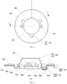
- FIG. 1 is a front view of an illumination module according to an exemplary embodiment of the present disclosure.
- FIG. 2 is an exploded view (front) of an illumination module according to an exemplary embodiment of the present disclosure.
- FIG. 3 is an exploded view (back) of an illumination module according to an exemplary embodiment of the present disclosure.
- FIG. 4 is a rear view of an illumination module according to an exemplary embodiment of the present disclosure.
- FIG. 5 is a cross-sectional view of FIG. 4 taken along A-A direction.
- FIG. 6 is a cross-sectional view of a magnetic component of an illumination module according to an exemplary embodiment of the present disclosure.
- FIG. 7 is a front view of an illumination module according to another exemplary embodiment of the present disclosure.
- FIG. 8 is a rear view of an illumination module according to another exemplary embodiment of the present disclosure.
- FIG. 9 is a cross-sectional view of FIG. 8 taken along B-B direction.
- the prior lighting module has a complex structure, troublesome assembly, and high manufacturing costs.
- an integrated lighting module is provided.
- the light source and the power supply driver are integrated into one body to facilitate replacement.
- the illumination module of the embodiment includes a light source 100 , a power supply driver 110 , an optical component 200 , and a plurality of magnetic components 300 .
- the light source 100 includes an annular circuit board 120 and a plurality of light sources 121 disposed on the annular circuit board 120 .
- the light source 121 is an LED light source, and a plurality of light sources 121 may all be white light source, warm yellow light source or partially white light source and partially warm yellow light source.
- the power supply driver 110 is electrically connected with the annular circuit board 120 , and the power supply driver 110 is electrically connected with the annular circuit board 120 by an inserting connection wire, and the power supply driver 110 drives the light source 121 to emit light.
- the annular circuit board 120 is provided with a plurality of avoidance holes 122 .
- the power supply driver 110 is connected with a reserved connecting wire for connecting with external commercial power, and when in use, it may be used by connecting the reserved connecting wire with the commercial power.
- the optical component 200 has opposite front and back surfaces, and the optical component 200 includes a power supply accommodating part 210 and a lens part 220 integrally connected to an around area of the power supply accommodating part 210 .
- the optical element 200 is made of transparent plastic and is formed by the integrally injection molding.
- the back surface of the power supply accommodating part 210 is provided with a power supply groove 211
- the front surface of the lens part 220 is provided with a light distribution structure
- a circuit snap-fit member 222 and a plurality of mounting part snap-fit member 223 are extended from the back surface of the lens part 220 .
- the mounting part snap-fit member 223 includes a plurality of first elastic parts 2231 which extend outward from the back surface of the lens part 220 and enclose a snap-fit space 2233 , and first snap-fit hooks 2232 extending from a side surface of the first elastic parts 2231 to the snap-fit space 2233 .
- the circuit snap-fit member 222 includes a plurality of second elastic parts 2221 extending outward from the edge of the back surface of the lens part 220 and second snap-fit hooks 2222 extending from a side surface of the second elastic parts 2221 and protruding towards the power supply accommodating part 210 , that is, the second snap-fit hooks 2222 extend towards the middle of the optical element 200 .
- Each magnetic component 300 includes a base 310 and a strong magnet 320 .
- the base 310 includes a combining part 311 and a snap-fit part 312 connected with the combining part 311 , and the strong magnet 320 is connected with the combining part 311 .
- the base 310 is made of plastic or metal by molding or stamping. In the embodiment, the base 310 is made of iron, the combining part 311 is provided with a combining hole 3111 , and the strong magnet 320 is absorbed and assembled in the combining hole 3111 .
- the snap-fit part 312 is in a snap-fit connection with the mounting part snap-fit member 223 , the snap-fit part 312 is provided with an annular groove 3121 , the snap-fit part 312 is inserted into the snap-fit space 2233 , and the first snap-fit hook 2232 is clamped into the annular groove 3121 for snap-fit connection.
- the annular circuit board 120 is arranged on the back surface of the lens part 220 and is in a snap-fit connection with the circuit snap-fit member 222 , and the annular circuit board 120 is clamped between the second snap-fit hooks 2222 and the lens part 220 .
- the plurality of light sources 121 are arranged corresponding to the light distribution structure 221 .
- the light distribution structure comprises a plurality of light distribution particles 221 a being in a one-to-one correspondence with the plurality of light sources 121 .
- the power supply driver 110 is embedded in the power supply groove 211 .
- the assembly is completed.
- the structure is simple, the assembly is convenient, the assembly can be completed without using any screws, the assembly efficiency is improved, and the manufacturing cost is lower.
- the lens part 220 is provided with a nailing through hole 224 .
- the illumination module may be installed on the installation target through the nailing through hole 224 by using screws and nails, so that the illumination module in the present disclosure has a broader disclosure scene.
- the illumination module also includes a power supply cover plate 400 , which is detachably connected with the power supply accommodating part 210 and covers the power supply groove 211 , and the power supply cover plate 400 is provided to prevent the power supply driver 110 from being away from the power supply groove 211 .
- a plurality of mounting part snap-fit members 223 are arranged near the power supply accommodating part 210 , the combining part 311 extends around the mounting part snap-fit member 223 , and the combining part 311 abuts against the power supply cover plate 400 to fix the power supply cover plate 400 .
- the power supply accommodating part 210 is provided with a third snap-fit hook 212
- the power supply cover plate 400 is provided with a snap-fit hook hole 410
- the third snap-fit hook 212 is in a snap-fit connection with the snap-fit hook hole 410 , so as to better prevent the power supply cover plate 400 from falling off.
- a side of the power supply cover plate 400 facing the power groove 211 is provided with a power supply snap-fit member 420 , and the power supply driver 110 is in a snap-fit connection with the power supply snap-fit member 420 , so that the power supply driver 110 is fixed on the power supply cover plate 400 , and the power supply driver 110 is prevented from being damaged by collision in the power supply groove 211 .
- FIGS. 7 to 9 another exemplary embodiment of an illumination module of the present disclosure is shown.
- This embodiment is basically the same as the previous embodiment, except that the light distribution structure in the embodiment is a light distribution convex ring 221 b.
- the optical component is integrally injection molded.
- the light distribution structure is a plurality of light distribution protrusions corresponding to the light sources in a one-to-one correspondence relationship.
- the light distribution structure is a light distribution convex ring.
- the mounting part snap-fit member comprises a plurality of first elastic parts extending outwards from the back surface of the lens part and enclosing a snap-fit space, and a first snap-fit hook extending from a side surface of the plurality of first elastic parts to the snap-fit space;
- the snap-fit part of the magnetic component is provided with an annular groove, the snap-fit part is inserted into the snap-fit space, and the first snap-fit hook is in a snap-fit connection with the annular groove.
- the lens part is provided with a nailing through hole.
- the circuit snap-fit member comprises a plurality of second elastic parts extending outwards from the edge of the back surface of the lens part and a plurality of second snap-fit hooks extending outwards from the side surface of the second elastic parts towards the power supply accommodating part; the annular circuit board is clamped between the second snap-fit hook and the lens part.
- the power supply cover plate is also included, and the power supply cover plate is detachably connected with the power supply accommodating part and covers the power supply groove.
- the power supply accommodating part is provided with a third snap-fit hook
- the power supply cover plate is provided with a snap-fit hook hole
- the third snap-fit hook is in a snap-fit connection with the snap-fit hook hole.
- a side of the power supply cover plate facing the power supply groove is provided with a power supply snap-fit member, and the power supply driver is in a snap-fit connection with the power supply snap-fit member.
- the plurality of mounting part snap-fit members is arranged at positions close to the power supply accommodating part, the combining part extend out of the periphery of the mounting part snap-fit member, and the combining part abuts against the power supply cover plate.
- the disclosure has the following advantages:
- the illumination module provided by the present disclosure is simple in structure and convenient to assemble, and can be assembled without using any screws, so that the assembly efficiency is improved and the manufacturing cost is lower.
Landscapes
- Engineering & Computer Science (AREA)
- General Engineering & Computer Science (AREA)
- Microelectronics & Electronic Packaging (AREA)
- Non-Portable Lighting Devices Or Systems Thereof (AREA)
- Arrangement Of Elements, Cooling, Sealing, Or The Like Of Lighting Devices (AREA)
Abstract
Description
Claims (20)
Applications Claiming Priority (3)
| Application Number | Priority Date | Filing Date | Title |
|---|---|---|---|
| CN202023293942.3 | 2020-12-31 | ||
| CN202023293942.3U CN215489382U (en) | 2020-12-31 | 2020-12-31 | Lighting module |
| PCT/CN2021/140427 WO2022143332A1 (en) | 2020-12-31 | 2021-12-22 | Lighting module |
Related Parent Applications (1)
| Application Number | Title | Priority Date | Filing Date |
|---|---|---|---|
| PCT/CN2021/140427 Continuation WO2022143332A1 (en) | 2020-12-31 | 2021-12-22 | Lighting module |
Publications (2)
| Publication Number | Publication Date |
|---|---|
| US20230341114A1 US20230341114A1 (en) | 2023-10-26 |
| US11994271B2 true US11994271B2 (en) | 2024-05-28 |
Family
ID=79718142
Family Applications (1)
| Application Number | Title | Priority Date | Filing Date |
|---|---|---|---|
| US18/215,150 Active US11994271B2 (en) | 2020-12-31 | 2023-06-27 | Illumination module with annular circuit board and magnetic supports |
Country Status (4)
| Country | Link |
|---|---|
| US (1) | US11994271B2 (en) |
| EP (1) | EP4246033A4 (en) |
| CN (1) | CN215489382U (en) |
| WO (1) | WO2022143332A1 (en) |
Families Citing this family (3)
| Publication number | Priority date | Publication date | Assignee | Title |
|---|---|---|---|---|
| CN115654449A (en) * | 2022-10-09 | 2023-01-31 | 欧普照明股份有限公司 | fan light |
| EP4607087A1 (en) * | 2022-10-09 | 2025-08-27 | Suzhou Opple Lighting Co., Ltd. | Fan lamp |
| USD1082095S1 (en) * | 2024-05-17 | 2025-07-01 | Zehao Chen | Plant light |
Citations (19)
| Publication number | Priority date | Publication date | Assignee | Title |
|---|---|---|---|---|
| US7997774B2 (en) * | 2005-02-10 | 2011-08-16 | Richard Graham Liddle | Light system having magnetically attachable lighting elements |
| US20140029252A1 (en) * | 2012-07-30 | 2014-01-30 | Toshiba Lighting & Technology Corporation | Lamp, lamp unit, and luminaire |
| US8651711B2 (en) * | 2009-02-02 | 2014-02-18 | Apex Technologies, Inc. | Modular lighting system and method employing loosely constrained magnetic structures |
| CN203442626U (en) | 2013-08-28 | 2014-02-19 | 深圳市客亿电子科技有限公司 | Light source panel structure of LED ceiling lamp |
| JP2015008149A (en) | 2014-08-26 | 2015-01-15 | 東芝ライテック株式会社 | Lamp with lamp and lighting equipment |
| CN105444071A (en) | 2015-12-24 | 2016-03-30 | 东莞中之光电股份有限公司 | Ceiling lamp |
| US9989198B2 (en) * | 2016-05-18 | 2018-06-05 | Michael Chen | Replacement LED light module |
| CN207569716U (en) | 2017-12-19 | 2018-07-03 | 深圳佳比泰智能照明股份有限公司 | Ceiling lamp pastes and intelligent ceiling lamp patch |
| CN207865124U (en) | 2017-12-28 | 2018-09-14 | 贵派电器股份有限公司 | A kind of ceiling lamp |
| US10352512B1 (en) * | 2017-05-18 | 2019-07-16 | S. Lynne Smith | Device for illuminating a door knob keyhole |
| US10401002B2 (en) * | 2014-09-22 | 2019-09-03 | Opple Lighting Co., Ltd. | LED lamp and LED light source module thereof |
| US20200018469A1 (en) | 2017-03-05 | 2020-01-16 | Ran Roland Kohen | Modular smart quick connect device for electrical fixtures |
| US10859217B2 (en) * | 2015-12-29 | 2020-12-08 | Opple Lighting Co., Ltd. | Light source apparatus and method of manufacturing the same |
| US10859248B2 (en) * | 2016-10-26 | 2020-12-08 | Opple Lighting Co., Ltd. | Light source module and lighting device |
| US10914452B2 (en) * | 2016-03-07 | 2021-02-09 | Opple Lighting Co., Ltd. | Optical element, light source circuit and lighting device |
| US11215347B2 (en) * | 2019-11-27 | 2022-01-04 | Xiamen Leedarson Lighting Co., Ltd | Lighting apparatus |
| US11353203B2 (en) * | 2020-04-28 | 2022-06-07 | Xiamen Leedarson Lighting Co., Ltd | Lighting apparatus with manual switch |
| US11623400B2 (en) * | 2020-02-03 | 2023-04-11 | Advanced Solutions Life Sciences, Llc | Modular light source for curing of 3D printed biological and engineered materials |
| US11686461B1 (en) * | 2021-12-10 | 2023-06-27 | Star Mount Enterprise Limited | Intelligent light source module and lighting fixture |
Family Cites Families (7)
| Publication number | Priority date | Publication date | Assignee | Title |
|---|---|---|---|---|
| WO2016090709A1 (en) * | 2014-12-12 | 2016-06-16 | 欧普照明股份有限公司 | Magnetic mounting element, optical module, illumination module and illumination lamp |
| CN204372729U (en) * | 2015-01-30 | 2015-06-03 | 中山市子弹头电器有限公司 | LED ceiling light |
| EP3385599B1 (en) * | 2015-12-03 | 2020-12-16 | Opple Lighting Co,. Ltd. | Optical element, illuminating module and illuminator with the illuminating module |
| CN207364712U (en) * | 2017-09-29 | 2018-05-15 | 惠州市德赛西威汽车电子股份有限公司 | A kind of automobile trunk flashlight of carry magnet |
| CN208204573U (en) * | 2018-04-17 | 2018-12-07 | 丁增科 | L ED lamp lens light source module |
| CN208382076U (en) * | 2018-06-26 | 2019-01-15 | 东莞市鑫昌铝制品有限公司 | A kind of aluminum profile of strip-shaped LED lamp |
| CN210891214U (en) * | 2019-12-03 | 2020-06-30 | 欧普照明股份有限公司 | Magnetic mounting element, optical module, lighting module and lighting fixture |
-
2020
- 2020-12-31 CN CN202023293942.3U patent/CN215489382U/en active Active
-
2021
- 2021-12-22 WO PCT/CN2021/140427 patent/WO2022143332A1/en not_active Ceased
- 2021-12-22 EP EP21914070.4A patent/EP4246033A4/en active Pending
-
2023
- 2023-06-27 US US18/215,150 patent/US11994271B2/en active Active
Patent Citations (21)
| Publication number | Priority date | Publication date | Assignee | Title |
|---|---|---|---|---|
| US7997774B2 (en) * | 2005-02-10 | 2011-08-16 | Richard Graham Liddle | Light system having magnetically attachable lighting elements |
| US8651711B2 (en) * | 2009-02-02 | 2014-02-18 | Apex Technologies, Inc. | Modular lighting system and method employing loosely constrained magnetic structures |
| US20140029252A1 (en) * | 2012-07-30 | 2014-01-30 | Toshiba Lighting & Technology Corporation | Lamp, lamp unit, and luminaire |
| CN203442626U (en) | 2013-08-28 | 2014-02-19 | 深圳市客亿电子科技有限公司 | Light source panel structure of LED ceiling lamp |
| JP2015008149A (en) | 2014-08-26 | 2015-01-15 | 東芝ライテック株式会社 | Lamp with lamp and lighting equipment |
| US10401002B2 (en) * | 2014-09-22 | 2019-09-03 | Opple Lighting Co., Ltd. | LED lamp and LED light source module thereof |
| CN105444071A (en) | 2015-12-24 | 2016-03-30 | 东莞中之光电股份有限公司 | Ceiling lamp |
| US10859217B2 (en) * | 2015-12-29 | 2020-12-08 | Opple Lighting Co., Ltd. | Light source apparatus and method of manufacturing the same |
| US10914452B2 (en) * | 2016-03-07 | 2021-02-09 | Opple Lighting Co., Ltd. | Optical element, light source circuit and lighting device |
| US9989198B2 (en) * | 2016-05-18 | 2018-06-05 | Michael Chen | Replacement LED light module |
| US10859248B2 (en) * | 2016-10-26 | 2020-12-08 | Opple Lighting Co., Ltd. | Light source module and lighting device |
| US20200018469A1 (en) | 2017-03-05 | 2020-01-16 | Ran Roland Kohen | Modular smart quick connect device for electrical fixtures |
| CN110741514A (en) | 2017-03-05 | 2020-01-31 | 拉恩·罗兰·科恩 | Modular intelligent quick-connect apparatus for electrical devices |
| US10989400B2 (en) | 2017-03-05 | 2021-04-27 | Ran Roland Kohen | Modular smart quick connect device for electrical fixtures |
| US10352512B1 (en) * | 2017-05-18 | 2019-07-16 | S. Lynne Smith | Device for illuminating a door knob keyhole |
| CN207569716U (en) | 2017-12-19 | 2018-07-03 | 深圳佳比泰智能照明股份有限公司 | Ceiling lamp pastes and intelligent ceiling lamp patch |
| CN207865124U (en) | 2017-12-28 | 2018-09-14 | 贵派电器股份有限公司 | A kind of ceiling lamp |
| US11215347B2 (en) * | 2019-11-27 | 2022-01-04 | Xiamen Leedarson Lighting Co., Ltd | Lighting apparatus |
| US11623400B2 (en) * | 2020-02-03 | 2023-04-11 | Advanced Solutions Life Sciences, Llc | Modular light source for curing of 3D printed biological and engineered materials |
| US11353203B2 (en) * | 2020-04-28 | 2022-06-07 | Xiamen Leedarson Lighting Co., Ltd | Lighting apparatus with manual switch |
| US11686461B1 (en) * | 2021-12-10 | 2023-06-27 | Star Mount Enterprise Limited | Intelligent light source module and lighting fixture |
Non-Patent Citations (1)
| Title |
|---|
| International Search Report of PCT Application No. PCT/CN2021/140427 dated Jan. 26, 2022 with English translation(4). |
Also Published As
| Publication number | Publication date |
|---|---|
| EP4246033A1 (en) | 2023-09-20 |
| EP4246033A4 (en) | 2024-05-08 |
| WO2022143332A1 (en) | 2022-07-07 |
| CN215489382U (en) | 2022-01-11 |
| US20230341114A1 (en) | 2023-10-26 |
Similar Documents
| Publication | Publication Date | Title |
|---|---|---|
| US11994271B2 (en) | Illumination module with annular circuit board and magnetic supports | |
| JP4856901B2 (en) | LED lamp and lamp reflector assembly | |
| US8894253B2 (en) | Heat transfer bracket for lighting fixture | |
| CN209101141U (en) | A kind of ceiling lamp and LED light source mould group and light source assembly | |
| US12044381B2 (en) | Light fixture with lightguide trim | |
| US9857069B2 (en) | Spherical lamp with easy heat dissipation | |
| US10436976B2 (en) | Ribs for sealing and aligning an outdoor lightguide luminaire | |
| US10436397B2 (en) | Concealer plate for a lighting fixture | |
| CN219867647U (en) | Direct type borderless panel lamp | |
| US8016453B2 (en) | LED lamp assembly | |
| CN211853708U (en) | LED (light-emitting diode) down lamp | |
| WO2022183515A1 (en) | Frameless panel light | |
| CN112689205A (en) | Router | |
| CN213513432U (en) | Light source modules and lighting fixtures | |
| CN219120414U (en) | Tunnel lamp and modularized tunnel lamp group | |
| KR20130052796A (en) | A led lighting apparatus | |
| CN216244101U (en) | Multilayer luminous lampshade assembly and ceiling lamp | |
| CN213930630U (en) | a lighting fixture | |
| CN212961185U (en) | Down lamp | |
| CN212056977U (en) | Lamp fitting | |
| CN212841034U (en) | Integrated vehicle lighting lamp | |
| CN211502653U (en) | Strip-shaped illuminating lamp | |
| CN112689204A (en) | Router | |
| CN224188494U (en) | Lighting fixtures | |
| CN223271123U (en) | Lamp set |
Legal Events
| Date | Code | Title | Description |
|---|---|---|---|
| FEPP | Fee payment procedure |
Free format text: ENTITY STATUS SET TO UNDISCOUNTED (ORIGINAL EVENT CODE: BIG.); ENTITY STATUS OF PATENT OWNER: LARGE ENTITY |
|
| AS | Assignment |
Owner name: SUZHOU OPPLE LIGHTING CO., LTD., CHINA Free format text: ASSIGNMENT OF ASSIGNORS INTEREST;ASSIGNORS:TANG, CAIBAO;ZHAO, JIN;REEL/FRAME:064091/0355 Effective date: 20230627 Owner name: OPPLE LIGHTING CO., LTD., CHINA Free format text: ASSIGNMENT OF ASSIGNORS INTEREST;ASSIGNORS:TANG, CAIBAO;ZHAO, JIN;REEL/FRAME:064091/0355 Effective date: 20230627 |
|
| STPP | Information on status: patent application and granting procedure in general |
Free format text: DOCKETED NEW CASE - READY FOR EXAMINATION |
|
| STPP | Information on status: patent application and granting procedure in general |
Free format text: NOTICE OF ALLOWANCE MAILED -- APPLICATION RECEIVED IN OFFICE OF PUBLICATIONS |
|
| STPP | Information on status: patent application and granting procedure in general |
Free format text: PUBLICATIONS -- ISSUE FEE PAYMENT VERIFIED |
|
| STCF | Information on status: patent grant |
Free format text: PATENTED CASE |