US11971525B2 - Camera optical lens - Google Patents
Camera optical lens Download PDFInfo
- Publication number
- US11971525B2 US11971525B2 US17/137,417 US202017137417A US11971525B2 US 11971525 B2 US11971525 B2 US 11971525B2 US 202017137417 A US202017137417 A US 202017137417A US 11971525 B2 US11971525 B2 US 11971525B2
- Authority
- US
- United States
- Prior art keywords
- lens
- camera optical
- denotes
- optical lens
- curvature radius
- Prior art date
- Legal status (The legal status is an assumption and is not a legal conclusion. Google has not performed a legal analysis and makes no representation as to the accuracy of the status listed.)
- Active, expires
Links
- 230000003287 optical effect Effects 0.000 title claims abstract description 247
- 230000004075 alteration Effects 0.000 description 21
- 238000010586 diagram Methods 0.000 description 16
- 230000006872 improvement Effects 0.000 description 13
- 238000003384 imaging method Methods 0.000 description 10
- 230000035945 sensitivity Effects 0.000 description 5
- 210000001747 pupil Anatomy 0.000 description 4
- 230000000712 assembly Effects 0.000 description 2
- 238000000429 assembly Methods 0.000 description 2
- 238000005516 engineering process Methods 0.000 description 2
- 239000000463 material Substances 0.000 description 2
- 239000004065 semiconductor Substances 0.000 description 2
- 230000000295 complement effect Effects 0.000 description 1
- 238000004519 manufacturing process Methods 0.000 description 1
- 229910044991 metal oxide Inorganic materials 0.000 description 1
- 150000004706 metal oxides Chemical class 0.000 description 1
- 238000012986 modification Methods 0.000 description 1
- 230000004048 modification Effects 0.000 description 1
- 238000012634 optical imaging Methods 0.000 description 1
- 238000007493 shaping process Methods 0.000 description 1
Images


Classifications
-
- G—PHYSICS
- G02—OPTICS
- G02B—OPTICAL ELEMENTS, SYSTEMS OR APPARATUS
- G02B13/00—Optical objectives specially designed for the purposes specified below
- G02B13/001—Miniaturised objectives for electronic devices, e.g. portable telephones, webcams, PDAs, small digital cameras
- G02B13/0015—Miniaturised objectives for electronic devices, e.g. portable telephones, webcams, PDAs, small digital cameras characterised by the lens design
- G02B13/002—Miniaturised objectives for electronic devices, e.g. portable telephones, webcams, PDAs, small digital cameras characterised by the lens design having at least one aspherical surface
- G02B13/0045—Miniaturised objectives for electronic devices, e.g. portable telephones, webcams, PDAs, small digital cameras characterised by the lens design having at least one aspherical surface having five or more lenses
-
- G—PHYSICS
- G02—OPTICS
- G02B—OPTICAL ELEMENTS, SYSTEMS OR APPARATUS
- G02B13/00—Optical objectives specially designed for the purposes specified below
- G02B13/18—Optical objectives specially designed for the purposes specified below with lenses having one or more non-spherical faces, e.g. for reducing geometrical aberration
-
- G—PHYSICS
- G02—OPTICS
- G02B—OPTICAL ELEMENTS, SYSTEMS OR APPARATUS
- G02B9/00—Optical objectives characterised both by the number of the components and their arrangements according to their sign, i.e. + or -
- G02B9/64—Optical objectives characterised both by the number of the components and their arrangements according to their sign, i.e. + or - having more than six components
Definitions
- the present disclosure relates to the field of optical lens, particular, to a camera optical lens suitable for handheld devices, such as smart phones and digital cameras, and imaging devices, such as monitors or PC lenses.
- the lens that is traditionally equipped in mobile phone cameras adopts a three-piece, four-piece, or even five-piece or six-piece lens structure.
- the eight-piece lens structure gradually appears in lens designs.
- the typical eight-piece lens already has good optical performance, its optical power, lens spacing and lens shape remain unreasonable to some extents, resulting in that the lens structure, which, even though, has excellent optical performance, is not able to meet the design requirement for large aperture, long focal length and ultra-thinness.
- an object of the present disclosure is to provide a camera optical lens that meets a design requirement of large aperture, long focal length and ultra-thinness while having excellent optical performance.
- the camera optical lens includes, from an object side to an image side in sequence: a first lens, a second, a third lens, a fourth lens, a fifth lens, a sixth lens, a seventh lens, and an eighth lens; the first lens has a positive refractive power, and the camera optical lens satisfies conditions of: 0.95 ⁇ f/TTL; 2.00 ⁇ f2/f ⁇ 5.00; and 0.20 ⁇ (R15+R16)/(R15 ⁇ R16) ⁇ 0.90; where TTL denotes a total optical length from an object-side surface of the first lens to an image surface of the camera optical lens along an optical axis; f denotes a focal length of the camera optical lens; f2 denotes a focal length of the second lens; R15 denotes a central curvature radius of an object-side surface of the eighth lens; and R16 denotes a central curvature radius of an image-side surface of the eighth lens.
- the camera optical lens further satisfies a condition of: 2.50 ⁇ R9/R10 ⁇ 22.00; where R9 denotes a curvature radius of an object-side surface of the fifth lens; and R10 denotes a curvature radius of an image-side surface of the fifth lens.
- the camera optical lens further satisfies conditions of: 0.29 ⁇ f1/f ⁇ 0.88; ⁇ 2.28 ⁇ (R1+R2)/(R1 ⁇ R2) ⁇ 0.74; and 0.08 ⁇ d1/TTL ⁇ 0.24; where f1 denotes a focal length of the first lens; R1 denotes a central curvature radius of the object-side surface of the first lens; R2 denotes a central curvature radius of an image-side surface of the first lens; and d1 denotes an on-axis thickness of the first lens.
- the camera optical lens further satisfies conditions of: 0.16 ⁇ (R3+R4)/(R3 ⁇ R4) ⁇ 0.88; and 0.03 ⁇ d3/TTL ⁇ 0.10; where R3 denotes a central curvature radius of an object-side surface of the second lens; R4 denotes a central curvature radius of an image-side surface of the second lens; and d3 denotes an on-axis thickness of the second lens.
- the camera optical lens further satisfies conditions of: ⁇ 1.13 ⁇ f3/f ⁇ 0.37; 0.46 ⁇ (R5+R6)/(R5 ⁇ R6) ⁇ 1.50; and 0.02 ⁇ d5/TTL ⁇ 0.06; where f3 denotes a focal length of the third lens; R5 denotes a central curvature radius of an object-side surface of the third lens; R6 denotes a central curvature radius of an image-side surface of the third lens; and d5 denotes an on-axis thickness of the third lens.
- the camera optical lens further satisfies conditions of: 0.58 ⁇ f4/f ⁇ 2.10; ⁇ 11.49 ⁇ (R7+R8)/(R7 ⁇ R8) ⁇ 3.58; and 0.02 ⁇ d7/TTL ⁇ 0.07; where f4 denotes a focal length of the fourth lens; R7 denotes a central curvature radius of an object-side surface of the fourth lens; R8 denotes a central curvature radius of an image-side surface of the fourth lens; and d7 denotes an on-axis thickness of the fourth lens.
- the camera optical lens further satisfies following conditions: ⁇ 3.14 ⁇ f5/f ⁇ 0.92; 0.55 ⁇ (R9+R10)/(R9 ⁇ R10) ⁇ 3.47; and 0.02 ⁇ d9/TTL ⁇ 0.06; where f5 denotes a focal length of the fifth lens; R9 denotes a curvature radius of an object-side surface of the fifth lens; R10 denotes a curvature radius of an image-side surface of the fifth lens; and d9 denotes an on-axis thickness of the fifth lens.
- the camera optical lens further satisfies a condition of: 1.56 ⁇ f6/f ⁇ 5.08; 0.52 ⁇ (R11+R12)/(R11 ⁇ R12) ⁇ 1.70; and 0.03 ⁇ d11/TTL ⁇ 0.09; where f6 denotes a focal length of the sixth lens; R11 denotes a central curvature radius of an object-side surface of the sixth lens; R12 denotes a central curvature radius of an image-side surface of the sixth lens; and d11 denotes an on-axis thickness of the sixth lens.
- the camera optical lens further satisfies a condition of: ⁇ 7.59 ⁇ f7/f ⁇ 2.07; 3.16 ⁇ (R13+R14)/(R13 ⁇ R14) ⁇ 11.46; and 0.02 ⁇ d13/TTL ⁇ 0.06; where f7 denotes a focal length of the seventh lens; R13 denotes a central curvature radius of an object-side surface of the seventh lens; R14 denotes a central curvature radius of an image-side surface of the seventh lens; and d13 denotes an on-axis thickness of the seventh lens.
- the camera optical lens further satisfies a condition of: ⁇ 5.53 ⁇ f8/f ⁇ 1.48; and 0.04 ⁇ d15/TTL ⁇ 0.14; where f8 denotes a focal length of the eighth lens; and d15 denotes an on-axis thickness of the eighth lens.
- the camera optical lens further satisfies a condition of: FNO ⁇ 1.87; where FNO denotes an F number of the camera optical lens.
- the camera optical lens further satisfies a condition of: f/IH ⁇ 2.23; where IH denotes an image height of the camera optical lens.
- the camera optical lens further satisfies a condition of: TTL/IH ⁇ 2.18; where IH denotes an image height of the camera optical lens.
- the present disclosure is advantageous in: the camera optical lens in the present disclosure has excellent optical performance and has characteristics of large aperture, long focal length and ultra-thinness, and is especially applicable to mobile phone camera lens assemblies and WEB camera lenses composed by such camera elements as CCD and CMOS for high pixels.
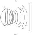
- FIG. 1 is a schematic diagram of a structure of a camera optical lens according to Embodiment 1 of the present disclosure.
- FIG. 2 is a schematic diagram of a longitudinal aberration of the camera optical lens shown in FIG. 1 .
- FIG. 3 is a schematic diagram of a lateral color of the camera optical lens shown in FIG. 1 .
- FIG. 4 is a schematic diagram of a field curvature and a distortion of the camera optical lens shown in FIG. 1 .
- FIG. 5 is a schematic diagram of a structure of a camera optical lens according to Embodiment 2 of the present disclosure.
- FIG. 6 is a schematic diagram of a longitudinal aberration of the camera optical lens shown in FIG. 5 .
- FIG. 7 is a schematic diagram of a lateral color of the camera optical lens shown in FIG. 5 .
- FIG. 8 is a schematic diagram of a field curvature and a distortion of the camera optical lens shown in FIG. 5 .
- FIG. 9 is a schematic diagram of a structure of a camera optical lens according to Embodiment 3 of the present disclosure.
- FIG. 10 is a schematic diagram of a longitudinal aberration of the camera optical lens shown in FIG. 9 .
- FIG. 11 is a schematic diagram of a lateral color of the camera optical lens shown in FIG. 9 .
- FIG. 12 is a schematic diagram of a field curvature and a distortion of the camera optical lens shown in FIG. 9 .
- FIG. 1 shows a schematic diagram of a camera optical lens 10 according to Embodiment 1 of the present disclosure, and the camera optical lens 10 includes eight lenses.
- an object side refers to the left side
- an image side refers to the right side
- the camera optical lens 10 includes, from the object side to the image side in sequence: an aperture S1, a first lens L 1 , a second lens L 2 , a third lens L 3 , a fourth lens L 4 , a fifth lens L 5 , a sixth lens L 6 , a seventh lens L 7 and an eighth lens L 8 .
- An optical element such as an optical filter GF can be arranged between the eighth lens L 8 and an image surface Si.
- the first lens L has a positive refractive power
- the second lens L 2 has a positive refractive power
- the third lens L 3 has a negative refractive power
- the fourth lens L 4 has a positive refractive power
- the fifth lens L 5 has a negative refractive power
- the sixth lens L 6 has a positive refractive power
- the seventh lens L 7 has a negative refractive power
- the eighth lens L 8 has a negative refractive power.
- the third lens L 3 , the fourth lens L 4 , the fifth lens L 5 , the sixth lens L 6 , the seventh lens L 7 and the eighth lens L 8 may have other refractive powers than those of this embodiment.
- the first lens L 1 has a positive refractive power, which facilitates improving performance of the camera optical lens.
- the first lens L 1 , the second lens L 2 , the third lens L 3 , the fourth lens L 4 , the fifth lens L 5 , the sixth lens L 6 , the seventh lens L 7 and the eighth lens L 8 are made of plastic material. In other embodiments, the lenses may be made of other material.
- a total optical length from the object side surface of the first lens L 1 to an image surface Si of the camera optical lens 10 along an optical axis is defined as TTL
- a focal length of the camera optical lens 10 is defined as f
- a focal length of the second lens L 2 is defined as f2
- a central curvature radius of the object-side surface of the eighth lens L 8 is defined as R15
- a central curvature radius of the image-side surface of the eighth lens L 8 is defined as R16.
- the camera optical lens 10 satisfies conditions of: 0.95 ⁇ f/TTL; (1) 2.00 ⁇ f 2/ f ⁇ 5.00; and (2) 0.20 ⁇ ( R 15+ R 16)/( R 15 ⁇ R 16) ⁇ 0.90.
- Condition (1) specifies a ratio of the focal length of the camera optical lens 10 and the total optical length of the camera optical lens 10 .
- the camera optical lens 10 has the focal length longer.
- the camera optical lens 10 satisfies a condition of 0.99 ⁇ f/TTL.
- Condition (2) specifies a ratio of the focal length of the second lens L 2 to the focal length of the camera optical lens 10 . Within this condition, a spherical aberration and a field curvature of the camera optical lens 10 can be effectively balanced.
- Condition (3) specifies a shape of the eighth lens L 8 . Within this condition, correction of the off-axis aberration is facilitated.
- a central curvature radius of the object-side surface of the fifth lens L 5 is defined as R9, and a central curvature radius of the image-side surface of the fifth lens L 5 is defined as R10.
- the camera optical lens 10 satisfies a condition of 2.50 ⁇ R9/R10 ⁇ 22.00, which specifies a shape of the fifth lens L 5 . Within this condition, the deflection degree of the light passing through the lens can be alleviated, and the aberration can be effectively reduced.
- the first lens L 1 includes an object-side surface being convex in a paraxial region and an image-side surface being concave in the paraxial region.
- the focal length of the camera optical lens 10 is defined as f, and a focal length of the first lens is defined as f1.
- the camera optical lens 10 satisfies a condition of 0.29 ⁇ f1/f ⁇ 0.88, which specifies a ratio of the focal length of the first lens L 1 to the focal length of the camera optical lens 10 .
- the first lens L 1 has an appropriate positive refractive power, the correction of the aberration of the camera optical lens 10 is facilitated, and meanwhile the development of the camera optical lens 10 towards ultra-thinness is facilitated.
- the camera optical lens 10 satisfies a condition of 0.46 ⁇ f1/f ⁇ 0.70.
- a central curvature radius of an object-side surface of the first lens L 1 is defined as R1, and a central curvature radius of an image-side surface of the first lens L 1 is defined as R2.
- the camera optical lens 10 satisfies a condition of ⁇ 2.28 ⁇ (R1+R2)/(R1 ⁇ R2) ⁇ 0.74. This can reasonably control a shape of the first lens L 1 in such a manner that the first lens L 1 can effectively correct a spherical aberration of the camera optical lens 10 .
- the camera optical lens 10 satisfies a condition of ⁇ 1.42 ⁇ (R1+R2)/(R1 ⁇ R2) ⁇ 0.92.
- the total optical length of the camera optical lens 10 is defined as TTL, and an on-axis thickness of the first lens L 1 is defined as d1.
- the camera optical lens 10 satisfies a condition of 0.08 ⁇ d1/TTL ⁇ 0.24. Within this condition, ultra-thinness of the lenses is facilitated.
- the camera optical lens 10 satisfies a condition of 0.13 ⁇ d1/TTL ⁇ 0.19.
- the second lens L 2 includes an object-side surface being convex in a paraxial region and an image-side surface being convex in the paraxial region.
- a central curvature radius of the object-side surface of the second lens L 2 is defined as R3, and a central curvature radius of the image-side surface of the second lens L 2 is defined as R4.
- the camera optical lens 10 satisfies a condition of 0.16 ⁇ (R3+R4)/(R3 ⁇ R4) ⁇ 0.88, which specifies a shape of the second lens L 2 . With development of the camera optical lens 10 towards ultra-thinness, correction of the on-axis chromatic aberration is facilitated. Preferably, the camera optical lens 10 satisfies a condition of 0.25 ⁇ (R3+R4)/(R3 ⁇ R4) ⁇ 0.70.
- the total optical length of the camera optical lens 10 is defined as TTL, and an on-axis thickness of the second lens L 2 is defines as d3.
- the camera optical lens 10 satisfies a condition of 0.03 ⁇ d3/TTL ⁇ 0.10. Within this condition, ultra-thinness of the lenses is facilitated.
- the camera optical lens 10 satisfies a condition of 0.05 ⁇ d3/TTL ⁇ 0.08.
- the third lens L 3 includes an object-side surface being concave in a paraxial region and an image-side surface being concave in the paraxial region.
- the focal length of the camera optical lens 10 is defined as f, and a focal length of the third lens L 3 is defined as f3.
- the camera optical lens 10 satisfies a condition of ⁇ 1.13 ⁇ f3/f ⁇ 0.37. With reasonable distribution of the refractive power, the camera optical lens 10 has better imaging quality and lower sensitivity. Preferably, the camera optical lens 10 satisfies a condition of ⁇ 0.71 ⁇ f3/f ⁇ 0.46.
- a central curvature radius of the object-side surface of the third lens L 3 is defined as R5, and a central curvature radius of the image-side surface of the third lens L 3 is defined as R6.
- the camera optical lens 10 satisfies a condition of 0.46 ⁇ (R5+R6)/(R5 ⁇ R6) ⁇ 1.50, which effectively controls a shape of the third lens L 3 and facilitates shaping of the third lens L 3 . Within this condition, the deflection degree of the light passing through the lens can be alleviated, and the aberration can be effectively reduced.
- the camera optical lens 10 satisfies a condition of 0.74 ⁇ (R5+R6)/(R5 ⁇ R6) ⁇ 1.20.
- the total optical length of the camera optical lens 10 is defined as TTL, and an on-axis thickness of the third lens L 3 is defined as d5.
- the camera optical lens 10 satisfies a condition of 0.02 ⁇ d5/TTL ⁇ 0.06. Within this condition, ultra-thinness of the lenses is facilitated.
- the camera optical lens 10 satisfies a condition of 0.03 ⁇ d5/TTL ⁇ 0.05.
- the fourth lens L 4 includes an object-side surface being convex in a paraxial region and an image-side surface being concave in the paraxial region.
- the focal length of the camera optical lens 10 is defined as f
- a focal length of the fourth lens L 4 is defined as f4.
- the camera optical lens 10 satisfies a condition of 0.58 ⁇ f4/f ⁇ 2.10, which specifies a ratio of the focal length of the fourth lens L 4 and the focal length of the camera optical lens 10 . Within this condition, improvement of performance of the camera optical lens 10 is facilitated.
- the camera optical lens 10 satisfies a condition of 0.93 ⁇ f4/f ⁇ 1.68.
- a central curvature radius of the object-side surface of the fourth lens L 4 is defined as R7, and a central curvature radius of the image-side surface of the fourth lens L 4 is defined as R8.
- the camera optical lens 10 satisfies a condition of ⁇ 11.49 ⁇ (R7+R8)/(R7 ⁇ R8) ⁇ 3.58, which specifies a shape of the fourth lens L 4 . Within this condition, the development of the lenses towards ultra-thinness would facilitate correcting the off-axis aberration.
- the camera optical lens 10 satisfies a condition of ⁇ 7.18 ⁇ (R7+R8)/(R7 ⁇ R8) ⁇ 4.48.
- the total optical length of the camera optical lens 10 is defined as TTL, and an on-axis thickness of the fourth lens L 4 is defined as d7.
- the camera optical lens 10 satisfies a condition of 0.02 ⁇ d7/TTL ⁇ 0.07. Within this condition, ultra-thinness of the lenses is facilitated.
- the camera optical lens 10 satisfies a condition of 0.04 ⁇ d7/TTL ⁇ 0.06.
- the fifth lens L 5 includes an object-side surface being convex in a paraxial region and an image-side surface being concave in the paraxial region.
- the focal length of the camera optical lens 10 is defined as f, and a focal length of the fifth lens L 5 is defined as f5.
- the camera optical lens 10 satisfies a condition of ⁇ 3.14 ⁇ f5/f ⁇ 0.92, which specifies the fifth lens L 5 so as to enable the light angle of the camera optical lens 10 to be gradual and reduce the tolerance sensitivity.
- the camera optical lens 10 satisfies a condition of ⁇ 1.96 ⁇ f5/f ⁇ 1.15.
- a central curvature radius of the object-side surface of the fifth lens L 5 is defined as R9, and a central curvature radius of the image-side surface of the fifth lens L 5 is defined as R10.
- the camera optical lens 10 satisfies a condition of 0.55 ⁇ (R9+R10)/(R9 ⁇ R10) ⁇ 3.47, which specifies a shape of the fifth lens L 5 . Within this condition, the development of the lenses towards ultra-thinness would facilitate correcting the off-axis aberration.
- the camera optical lens 10 satisfies a condition of 0.88 ⁇ (R9+R10)/(R9 ⁇ R10) ⁇ 2.77.
- the total optical length of the camera optical lens 10 is defined as TTL, and an on-axis thickness of the fifth lens L 5 is defined as d9.
- the camera optical lens 10 satisfies a condition of 0.02 ⁇ d9/TTL ⁇ 0.06. Within this condition, ultra-thinness of the lenses is facilitated.
- the camera optical lens 10 satisfies a condition of 0.03 ⁇ d9/TTL ⁇ 0.05.
- the sixth lens L 6 includes an object-side surface being concave in a paraxial region and an image-side surface being convex in the paraxial region.
- the focal length of the camera optical lens 10 is defined as f, and a focal length of the sixth lens L 6 is defined as f6.
- the camera optical lens 10 satisfies a condition of 1.56 ⁇ f6/f ⁇ 5.08. With reasonable distribution of the refractive power, the camera optical lens 10 has better imaging quality and lower sensitivity. Preferably, the camera optical lens 10 satisfies a condition of 2.50 ⁇ f6/f ⁇ 4.07.
- a central curvature radius of an object-side surface of the sixth lens L 6 is defined as R11, and a central curvature radius of an image-side surface of the sixth lens L 6 is defined as R12.
- the camera optical lens 10 satisfies a condition of 0.52 ⁇ (R11+R12)/(R11 ⁇ R12) ⁇ 1.70, which specifies a shape of the sixth lens L 6 . Within this condition, the development of the lenses towards ultra-thinness would facilitate correcting the off-axis aberration.
- the camera optical lens 10 satisfies a condition of 0.82 ⁇ (R11+R12)/(R11 ⁇ R12) ⁇ 1.36.
- the total optical length of the camera optical lens 10 is defined as TTL, and an on-axis thickness of the sixth lens L 6 is defined as d11.
- the camera optical lens 10 satisfies a condition of 0.03 ⁇ d11/TTL ⁇ 0.09. Within this condition, ultra-thinness of the lenses is facilitated.
- the camera optical lens 10 satisfies a condition of 0.05 ⁇ d11/TTL ⁇ 0.08.
- the seventh lens L 7 includes an object-side surface being convex in a paraxial region and an image-side surface being concave in the paraxial region.
- the focal length of the camera optical lens 10 is defined as f, and a focal length of the seventh lens L 7 is defined as f7.
- the camera optical lens 10 satisfies a condition of ⁇ 7.59 ⁇ f7/f ⁇ 2.07. With reasonable distribution of the refractive power, the camera optical lens 10 has better imaging quality and lower sensitivity. Preferably, the camera optical lens 10 satisfies a condition of ⁇ 4.75 ⁇ f7/f ⁇ 2.59.
- a central curvature radius of the object-side surface of the seventh lens L 7 is defined as R13, and a central curvature radius of the image-side surface of the seventh lens L 7 is defined as R14.
- the camera optical lens 10 satisfies a condition of 3.16 ⁇ (R13+R14)/(R13 ⁇ R14) ⁇ 11.46, which specifies a shape of the seventh lens L 7 . Within this condition, the development of the lenses towards ultra-thinness would facilitate correcting the off-axis aberration.
- the camera optical lens 10 satisfies a condition of 5.06 ⁇ (R13+R14)/(R13 ⁇ R14) ⁇ 9.17.
- the total optical length of the camera optical lens 10 is defined as TTL, and an on-axis thickness of the seventh lens L 7 is defined as d13.
- the camera optical lens 10 satisfies a condition of 0.02 ⁇ d13/TTL ⁇ 0.06. Within this condition, ultra-thinness of the lenses is facilitated.
- the camera optical lens 10 satisfies a condition of 0.03 ⁇ d13/TTL ⁇ 0.05.
- the eighth lens L 8 includes an object-side surface being concave in a paraxial region and an image-side surface being concave in the paraxial region.
- the focal length of the camera optical lens 10 is defined as f, and a focal length of the eighth lens L 8 is defined as f8.
- the camera optical lens 10 satisfies a condition of ⁇ 5.53 ⁇ f8/f ⁇ 1.48. With reasonable distribution of the refractive power, the camera optical lens 10 has better imaging quality and lower sensitivity. Preferably, the camera optical lens 10 satisfies a condition of ⁇ 3.46 ⁇ f8/f ⁇ 1.86.
- the total optical length of the camera optical lens 10 is defined as TTL, and an on-axis thickness of the eighth lens L 8 is defined as d15.
- the camera optical lens 10 satisfies a condition of 0.04 ⁇ d15/TTL ⁇ 0.14. Within this condition, ultra-thinness of the lenses is facilitated.
- the camera optical lens 10 satisfies a condition of 0.07 ⁇ d15/TTL ⁇ 0.11.
- configuration of the object-side surfaces and the image-side surfaces of the first lens L 1 , the second lens L 2 , the third lens L 3 , the fourth lens L 4 , the fifth lens L 5 , the sixth lens L 6 , the seventh lens L 7 and the eighth lens L 8 may have a distribution in convex and concave other than that of the above-discussed embodiment.
- an F number of the camera optical lens 10 is defined as FNO, and the camera optical lens 10 satisfies a condition of FNO ⁇ 1.87. This enables the camera optical lens 10 to achieve large aperture and excellent imaging performance.
- an image height of the camera optical lens 10 is defined as IH, and the focal length of the camera optical lens 10 is defined as f.
- the camera optical lens 10 satisfies a condition of f/IH ⁇ 2.23, which enables the camera optical lens 10 to achieve long focal length.
- the image height of the camera optical lens 10 is defined as IH, and the total optical length of the camera optical lens 10 is defined as TTL.
- the camera optical lens 10 satisfies a condition of TTL/IH ⁇ 2.18, which facilitates ultra-thinness of the lenses.
- the focal length of the camera optical lens 10 is defined as f
- a combined focal length of the first lens L 1 and of the second lens L 2 is defined as f12.
- the camera optical lens 10 satisfies a condition of 0.24 ⁇ f12/f ⁇ 0.79. Within this condition, the aberration and distortion of the camera optical lens 10 can be eliminated and a back focal length of the camera optical lens is reduced, thereby maintaining miniaturization of the camera optical lens.
- the camera optical lens 10 satisfies a condition of 0.38 ⁇ f12/f ⁇ 0.63.
- the camera optical lens 10 meets the design requirements of large aperture, long focal length and ultra-thinness while having excellent optical imaging performance. Based on the characteristics of the camera optical lens 10 , the camera optical lens 10 is particularly applicable to mobile camera lens assemblies and WEB camera lenses composed of such camera elements as CCD and CMOS for high pixels.
- the camera optical lens 10 will be further described with reference to the following examples. Symbols used in various examples are shown as follows.
- the focal length, on-axis distance, central curvature radius, on-axis thickness, inflexion point position, and arrest point position are all in units of mm.
- TTL Total optical length (the distance from the object side surface of the first lens L 1 to the image surface Si of the camera optical lens along the optical axis) in mm.
- FNO ratio of an effective focal length and an entrance pupil diameter of the camera optical lens.
- inflexion points and/or arrest points can be arranged on the object-side surface and/or the image-side surface of the lenses, so as to satisfy the demand for high quality imaging.
- inflexion points and/or arrest points can be arranged on the object-side surface and/or the image-side surface of the lenses, so as to satisfy the demand for high quality imaging.
- the description below can be referred for specific implementations.
- the design data of the camera optical lens 10 in Embodiment 1 of the present disclosure are shown in Table 1 and Table 2.
- R central curvature radius of an optical surface
- R1 central curvature radius of the object-side surface of the first lens L 1 ;
- R2 central curvature radius of the image-side surface of the first lens L 1 ;
- R3 central curvature radius of the object-side surface of the second lens L 2 ;
- R4 central curvature radius of the image-side surface of the second lens L 2 ;
- R5 central curvature radius of the object-side surface of the third lens L 3 ;
- R6 central curvature radius of the image-side surface of the third lens L 3 ;
- R7 central curvature radius of the object-side surface of the fourth lens L 4 ;
- R8 central curvature radius of the image-side surface of the fourth lens L 4 ;
- R9 central curvature radius of the object-side surface of the fifth lens L 5 ;
- R10 central curvature radius of the image-side surface of the fifth lens L 5 ;
- R11 central curvature radius of the object-side surface of the sixth lens L 6 ;
- R12 central curvature radius of the image-side surface of the sixth lens L 6 ;
- R13 central curvature radius of the object-side surface of the seventh lens L 7 ;
- R14 central curvature radius of the image-side surface of the seventh lens L 7 ;
- R15 central curvature radius of an object-side surface of the eighth lens L 8 ;
- R16 central curvature radius of an image-side surface of the eighth lens L 8 ;
- R17 central curvature radius of an object-side surface of the optical filter GF
- R18 central curvature radius of an image-side surface of the optical filter GF
- d on-axis thickness of a lens and an on-axis distance between lenses
- d17 on-axis thickness of the optical filter GF
- nd refractive index of the d line
- nd1 refractive index of the d line of the first lens L 1 ;
- nd2 refractive index of the d line of the second lens L 2 ;
- nd3 refractive index of the d line of the third lens L 3 ;
- nd4 refractive index of the d line of the fourth lens L 4 ;
- nd5 refractive index of the d line of the fifth lens L 5 ;
- nd6 refractive index of the d line of the sixth lens L 6 ;
- nd7 refractive index of the d line of the seventh lens L 7 ;
- nd8 refractive index of the d line of the eighth lens L 8 ;
- ndg refractive index of the d line of the optical filter GF
- ⁇ g abbe number of the optical filter GF.
- Table 2 shows aspheric surface data of the camera optical lens 10 in Embodiment 1 of the present disclosure.
- K is a conic coefficient
- A4, A6, A8, A10, A12, A14, A16, A18 and A20 are aspheric surface coefficients.
- y ( x 2 /R )/ ⁇ 1+[1 ⁇ ( k+ 1)( x 2 /R 2 )] 1/2 ⁇ +A 4 x 4 +A 6 x 6 +A 8 x 8 +A 10 x 10 +A 12 x 12 +A 14 x 14 +A 16 x 16 +A 18 x 18 +A 20 x 20 (4)
- x denotes a vertical distance between a point in the aspheric curve and the optical axis
- y denotes an aspheric depth (i.e. a vertical distance between the point having a distance of x from the optical axis and a plane tangent to the vertex on the optical axis of the aspheric surface).
- an aspheric surface of each lens surface uses the aspheric surfaces shown in the above formula (1).
- the present disclosure is not limited to the aspherical polynomials form shown in the formula (1).
- Table 3 and Table 4 show design data of inflexion points and arrest points of each lens of the camera optical lens 10 according to Embodiment 1 of the present disclosure.
- P1R1 and P1R2 represent the object-side surface and the image-side surface of the first lens L 1
- P2R1 and P2R2 represent the object-side surface and the image-side surface of the second lens L 2
- P3R1 and P3R2 represent the object-side surface and the image-side surface of the third lens L 3
- P4R1 and P4R2 represent the object-side surface and the image-side surface of the fourth lens L 4
- P5R1 and P5R2 represent the object-side surface and the image-side surface of the fifth lens L 5
- P6R1 and P6R2 represent the object-side surface and the image-side surface of the sixth lens L 6
- P7R1 and P7R2 represent the object-side surface and the image-side surface of the seventh lens L 7
- P8R1 and P8R2 represent the object-
- inflexion point position refers to vertical distances from inflexion points arranged on each lens surface to the optic axis of the camera optical lens 10 .
- arrest point position refers to vertical distances from arrest points arranged on each lens surface to the optical axis of the camera optical lens 10 .
- FIG. 2 and FIG. 3 illustrate a longitudinal aberration and a lateral color of light with wavelengths of 656 nm, 587 nm, 546 nm, 486 nm and 436 nm after passing the camera optical lens 10 in Embodiment 1, respectively.
- FIG. 4 illustrates a schematic diagram of a field curvature and a distortion of light with a wavelength of 546 nm after passing the camera optical lens 10 in Embodiment 1.
- a field curvature S in FIG. 4 is a field curvature in a sagittal direction
- T is a field curvature in a tangential direction.
- Embodiment 1 satisfies the various conditions.
- an entrance pupil diameter (ENPD) of the camera optical lens 10 is 3.300 mm
- an image height (IH) of 1.0H is 2.750 mm
- a field of view (FOV) in a diagonal direction is 47.48°.
- the camera optical lens 10 achieves large aperture, long focal length and ultra-thinness, the on-axis and off-axis chromatic aberration is sufficiently corrected, thereby achieving excellent optical performance.
- Embodiment 2 which provides a camera optical lens 20 structurally shown in FIG. 5 , is basically the same as Embodiment 1 and involves symbols having the same meanings as Embodiment 1, and only differences therebetween will be described in the following.
- Table 5 and Table 6 show design data of a camera optical lens 20 in Embodiment 2 of the present disclosure.
- Table 6 shows aspheric surface data of each lens of the camera optical lens 20 in Embodiment 2 of the present disclosure.
- Table 7 and table 8 show design data of inflexion points and arrest points of each lens of the camera optical lens 20 in Embodiment 2 of the present disclosure.
- FIG. 6 and FIG. 7 illustrate a longitudinal aberration and a lateral color of light with wavelengths of 656 nm, 587 nm, 546 nm, 486 nm and 436 nm after passing the camera optical lens 20 in Embodiment 2, respectively.
- FIG. 8 illustrates a schematic diagram of a field curvature and a distortion of light with a wavelength of 546 nm after passing the camera optical lens 20 in Embodiment 2.
- a field curvature S in FIG. 8 is a field curvature in a sagittal direction
- T is a field curvature in a tangential direction.
- the camera optical lens 20 in Embodiment 2 satisfies the various conditions.
- an entrance pupil diameter (ENPD) of the camera optical lens 20 is 3.301 mm
- an image height (IH) of 1.0H is 2.750 mm
- a field of view (FOV) in the diagonal direction is 47.46°.
- Embodiment 3 which provides a camera optical lens 30 structurally shown in FIG. 9 , is basically the same as Embodiment 1 and involves symbols having the same meanings as Embodiment 1, and only differences therebetween will be described in the following.
- the third lens L 3 includes an object-side surface being convex in a paraxial region.
- Table 9 and Table 10 show design data of a camera optical lens 30 in Embodiment 3 of the present disclosure.
- Table 10 shows aspheric surface data of each lens of the camera optical lens 30 in Embodiment 3 of the present disclosure.
- Table 11 and Table 12 show design data of inflexion points and arrest points of each lens in the camera optical lens 30 in Embodiment 3 of the present disclosure.
- FIG. 10 and FIG. 11 illustrate a longitudinal aberration and a lateral color of light with wavelengths of 656 nm, 587 nm, 546 nm, 486 nm and 436 nm after passing the camera optical lens 30 in Embodiment 3, respectively.
- FIG. 12 illustrates a schematic diagram of a field curvature and a distortion of light with a wavelength of 546 nm after passing the camera optical lens 30 in Embodiment 3.
- a field curvature S in FIG. 12 is a field curvature in a sagittal direction
- T is a field curvature in a tangential direction.
- the subsequent Table 13 lists values corresponding to the various conditions in the embodiments according to the above conditions. Consequently, the camera optical lens 30 in Embodiment 3 satisfies the various conditions.
- an entrance pupil diameter (ENPD) of the camera optical lens 30 is 3.306 mm
- an image height (IH) of 1.0H is 2.750 mm
- a field of view (FOV) in the diagonal direction is 47.39°.
Landscapes
- Physics & Mathematics (AREA)
- General Physics & Mathematics (AREA)
- Optics & Photonics (AREA)
- Lenses (AREA)
Abstract
Description
0.95≤f/TTL; (1)
2.00≤f2/f≤5.00; and (2)
0.20≤(R15+R16)/(R15−R16)≤0.90. (3)
| TABLE 1 | ||||
| R | d | nd | νd | |
| S1 | ∞ | d0 = | −0.842 | ||||
| R1 | 1.852 | d1 = | 0.942 | nd1 | 1.5444 | ν1 | 55.82 |
| R2 | 33.899 | d2 = | 0.060 | ||||
| R3 | 45.835 | d3 = | 0.382 | nd2 | 1.5444 | ν2 | 55.82 |
| R4 | −16.297 | d4 = | 0.052 | ||||
| R5 | −138.728 | d5 = | 0.241 | nd3 | 1.6701 | ν3 | 19.39 |
| R6 | 2.391 | d6 = | 0.111 | ||||
| R7 | 1.741 | d7 = | 0.283 | nd4 | 1.6400 | ν4 | 23.54 |
| R8 | 2.496 | d8 = | 0.215 | ||||
| R9 | 10.090 | d9 = | 0.240 | nd5 | 1.5444 | ν5 | 55.82 |
| R10 | 3.399 | d10 = | 0.452 | ||||
| R11 | −239.579 | d11 = | 0.375 | nd6 | 1.6701 | ν6 | 19.39 |
| R12 | −12.656 | d12 = | 0.590 | ||||
| R13 | 3.422 | d13 = | 0.240 | nd7 | 1.5444 | ν7 | 55.82 |
| R14 | 2.63 | d14 = | 0.460 | ||||
| R15 | −18.897 | d15 = | 0.535 | nd8 | 1.5444 | ν8 | 55.82 |
| R16 | 12.49 | d16 = | 0.302 | ||||
| R17 | ∞ | d17 = | 0.110 | ndg | 1.5168 | νg | 64.17 |
| R18 | ∞ | d18 = | 0.378 | ||||
| TABLE 2 | ||
| Conic | ||
| coefficient | Aspheric surface coefficients | |
| k | A4 | A6 | A8 | A10 | A12 | |
| R1 | 6.2697E−02 | −9.4460E−03 | 2.4453E−03 | 2.3374E−03 | −8.0042E−03 | 7.0261E−03 |
| R2 | 3.9721E+02 | 1.8622E−02 | 2.8016E−03 | −6.9051E−04 | −4.3418E−04 | −1.6350E−04 |
| R3 | 4.6622E+02 | 2.5817E−02 | 1.2349E−03 | −3.3787E−04 | −7.9502E−05 | 1.2613E−04 |
| R4 | −6.4762E+02 | −2.9752E−02 | 3.4361E−02 | −1.8931E−02 | 1.1171E−02 | −7.6361E−03 |
| R5 | 1.0000E+03 | −1.7944E−02 | 3.0631E−02 | −1.2998E−02 | 1.2962E−02 | −1.8317E−02 |
| R6 | 1.1231E+00 | −1.1397E−01 | 7.9562E−02 | −5.0891E−02 | 5.8097E−02 | −8.7859E−02 |
| R7 | −2.8459E−01 | −1.5313E−01 | 2.8289E−02 | 1.5846E−02 | 2.1490E−03 | −1.0395E−01 |
| R8 | −1.7459E+01 | 3.0690E−02 | −3.2812E−02 | −1.3397E−01 | 7.6175E−01 | −1.7208E+00 |
| R9 | −8.4606E+02 | −9.8736E−02 | 5.0670E−02 | 3.1494E−01 | −7.5248E−01 | 1.2086E+00 |
| R10 | −5.0070E+01 | −4.2466E−02 | 1.7662E−01 | −4.0352E−01 | 1.1680E+00 | −2.4716E+00 |
| R11 | 1.0000E+03 | −1.0418E−01 | −5.8519E−02 | 2.5322E−01 | −6.7328E−01 | 1.0506E+00 |
| R12 | 8.4678E+01 | −9.3380E−02 | 3.3945E−02 | −8.9908E−02 | 1.8015E−01 | −2.4099E−01 |
| R13 | −5.0475E+01 | −1.4587E−01 | 1.2567E−03 | 8.3911E−02 | −2.7577E−01 | 3.3228E−01 |
| R14 | −2.5740E+01 | −1.9041E−01 | 1.9748E−01 | −2.1642E−01 | 1.0456E−01 | −4.2181E−03 |
| R15 | 2.1026E+01 | −2.9957E−01 | 4.2802E−01 | −3.7319E−01 | 2.0807E−01 | −7.5643E−02 |
| R16 | 2.8319E+01 | −2.8732E−01 | 3.2530E−01 | −2.6792E−01 | 1.5535E−01 | −6.2191E−02 |
| Conic | ||
| coefficient | Aspheric surface coefficients |
| k | A14 | A16 | A18 | A20 | |
| R1 | 6.2697E−02 | −3.5533E−03 | 1.0970E−03 | −2.0855E−04 | 1.6274E−05 |
| R2 | 3.9721E+02 | −2.1986E−05 | 1.7289E−05 | 4.7623E−08 | 8.8584E−08 |
| R3 | 4.6622E+02 | 5.6955E−05 | −1.0372E−05 | −4.1243E−07 | 4.5565E−07 |
| R4 | −6.4762E+02 | 5.2308E−03 | −2.2503E−03 | 5.0713E−04 | −4.9398E−05 |
| R5 | 1.0000E+03 | 1.5292E−02 | −7.1679E−03 | 1.7991E−03 | −1.8790E−04 |
| R6 | 1.1231E+00 | 8.0566E−02 | −4.5629E−02 | 1.4357E−02 | −1.8305E−03 |
| R7 | −2.8459E−01 | 1.3592E−01 | −7.5889E−02 | 2.0702E−02 | −2.3292E−03 |
| R8 | −1.7459E+01 | 2.3045E+00 | −1.8402E+00 | 8.2002E−01 | −1.5658E−01 |
| R9 | −8.4606E+02 | −1.3830E+00 | 1.0377E+00 | −4.3297E−01 | 7.3589E−02 |
| R10 | −5.0070E+01 | 3.4184E+00 | −2.8993E+00 | 1.3611E+00 | −2.6869E−01 |
| R11 | 1.0000E+03 | −1.0447E+00 | 6.6128E−01 | −2.5368E−01 | 4.6198E−02 |
| R12 | 8.4678E+01 | 2.0004E−01 | −9.7065E−02 | 2.4147E−02 | −2.0995E−03 |
| R13 | −5.0475E+01 | −2.0026E−01 | 6.5946E−02 | −1.1336E−02 | 7.9440E−04 |
| R14 | −2.5740E+01 | −1.5202E−02 | 6.1312E−03 | −1.0031E−03 | 6.2262E−05 |
| R15 | 2.1026E+01 | 1.8042E−02 | −2.7521E−03 | 2.4592E−04 | −9.8671E−06 |
| R16 | 2.8319E+01 | 1.6535E−02 | −2.7641E−03 | 2.6203E−04 | −1.0721E−05 |
y=(x 2 /R)/{1+[1−(k+1)(x 2 /R 2)]1/2 }+A4x 4 +A6x 6 +A8x 8 +A10x 10 +A12x 12 +A14x 14 +A16x 16 +A18x 18 +A20x 20 (4)
| TABLE 3 | ||||
| Number(s) of | Inflexion point | Inflexion point | Inflexion point | |
| inflexion points | |
position 2 | position 3 | |
| |
1 | 1.505 | / | |
| P1R2 | ||||
| 1 | 1.305 | / | | |
| P2R1 | ||||
| 0 | / | | / | |
| P2R2 | ||||
| 1 | 0.785 | / | | |
| P3R1 | ||||
| 1 | 0.565 | / | | |
| P3R2 | ||||
| 1 | 1.025 | / | | |
| P4R1 | ||||
| 1 | 0.685 | / | | |
| P4R2 | ||||
| 0 | / | / | / | |
| P5R1 | 2 | 0.235 | 0.575 | / |
| |
0 | / | | / |
| P6R1 | ||||
| 0 | / | | / | |
| P6R2 | ||||
| 1 | 1.285 | / | / | |
| P7R1 | 2 | 0.325 | 1.385 | / |
| |
1 | 0.365 | / | / |
| P8R1 | 2 | 1.435 | 2.025 | / |
| P8R2 | 3 | 0.165 | 2.045 | 2.205 |
| TABLE 4 | |||
| Number(s) of | Arrest point | Arrest point | |
| arrest points | |
position 2 | |
| |
0 | / | / |
| |
0 | / | / |
| |
0 | / | / |
| |
1 | 1.135 | / |
| |
1 | 0.775 | / |
| |
0 | / | / |
| |
1 | 1.145 | / |
| |
0 | / | / |
| P5R1 | 2 | 0.475 | 0.635 |
| |
0 | / | / |
| |
0 | / | / |
| |
0 | / | / |
| |
1 | 0.575 | / |
| |
1 | 0.695 | / |
| |
0 | / | / |
| |
1 | 0.285 | / |
| TABLE 5 | ||||
| R | d | nd | νd | |
| S1 | ∞ | d0 = | −0.843 | ||||
| R1 | 1.862 | d1 = | 0.948 | nd1 | 1.5444 | ν1 | 55.82 |
| R2 | 28.909 | d2 = | 0.060 | ||||
| R3 | 32.557 | d3 = | 0.394 | nd2 | 1.5444 | ν2 | 55.82 |
| R4 | −8.467 | d4 = | 0.030 | ||||
| R5 | −58.733 | d5 = | 0.240 | nd3 | 1.6701 | ν3 | 19.39 |
| R6 | 2.384 | d6 = | 0.130 | ||||
| R7 | 1.877 | d7 = | 0.280 | nd4 | 1.6400 | ν4 | 23.54 |
| R8 | 2.668 | d8 = | 0.211 | ||||
| R9 | 96.645 | d9 = | 0.240 | nd5 | 1.5444 | ν5 | 55.82 |
| R10 | 4.416 | d10 = | 0.438 | ||||
| R11 | −861.451 | d11 = | 0.372 | nd6 | 1.6701 | ν6 | 19.39 |
| R12 | −12.815 | d12 = | 0.589 | ||||
| R13 | 3.667 | d13 = | 0.240 | nd7 | 1.5444 | ν7 | 55.82 |
| R14 | 2.666 | d14 = | 0.444 | ||||
| R15 | −34.715 | d15 = | 0.550 | nd8 | 1.5444 | ν8 | 55.82 |
| R16 | 10.081 | d16 = | 0.303 | ||||
| R17 | ∞ | d17 = | 0.110 | ndg | 1.5168 | νg | 64.17 |
| R18 | ∞ | d18 = | 0.389 | ||||
| TABLE 6 | ||
| Conic | ||
| coefficient | Aspheric surface coefficients | |
| k | A4 | A6 | A8 | A10 | A12 | |
| R1 | 6.3670E−02 | −8.9300E−03 | 2.6799E−03 | 2.2823E−03 | −7.9993E−03 | 7.0315E−03 |
| R2 | 2.7058E+02 | 1.8266E−02 | 2.1752E−03 | −7.5123E−04 | −4.2062E−04 | −1.5122E−04 |
| R3 | 2.5688E+02 | 2.1860E−02 | 1.6422E−03 | −3.2883E−04 | −7.2669E−05 | 1.2955E−04 |
| R4 | −2.1216E+02 | −2.6096E−02 | 3.4649E−02 | −1.9173E−02 | 1.1096E−02 | −7.6461E−03 |
| R5 | −2.9537E+02 | −1.5350E−02 | 2.9515E−02 | −1.3225E−02 | 1.2931E−02 | −1.8301E−02 |
| R6 | 1.0296E+00 | −1.1804E−01 | 8.0873E−02 | −5.2241E−02 | 5.7808E−02 | −8.7626E−02 |
| R7 | −1.9635E−01 | −1.4735E−01 | 2.3129E−02 | 1.5315E−02 | 2.8731E−03 | −1.0326E−01 |
| R8 | −1.8990E+01 | 1.6307E−02 | −3.8173E−02 | −1.3073E−01 | 7.6394E−01 | −1.7215E+00 |
| R9 | −6.7861E+02 | −1.0321E−01 | 5.7740E−02 | 3.1032E−01 | −7.5407E−01 | 1.2097E+00 |
| R10 | −6.5447E+01 | −3.5251E−02 | 1.7845E−01 | −4.0511E−01 | 1.1679E+00 | −2.4717E+00 |
| R11 | −7.2026E+02 | −9.9865E−02 | −6.1167E−02 | 2.5483E−01 | −6.7465E−01 | 1.0515E+00 |
| R12 | 8.8011E+01 | −8.9490E−02 | 3.2862E−02 | −9.0519E−02 | 1.8095E−01 | −2.4095E−01 |
| R13 | −6.0341E+01 | −1.4906E−01 | 2.4076E−03 | 8.4045E−02 | −2.7571E−01 | 3.3230E−01 |
| R14 | −2.8090E+01 | −1.9174E−01 | 1.9808E−01 | −2.1647E−01 | 1.0455E−01 | −4.2029E−03 |
| R15 | 1.5697E+02 | −3.0417E−01 | 4.2829E−01 | −3.7309E−01 | 2.0808E−01 | −7.5644E−02 |
| R16 | 1.7949E+01 | −2.9043E−01 | 3.2557E−01 | −2.6790E−01 | 1.5534E−01 | −6.2192E−02 |
| Conic | ||
| coefficient | Aspheric surface coefficients |
| k | A14 | A16 | A18 | A20 | |
| R1 | 6.3670E−02 | −3.5488E−03 | 1.0969E−03 | −2.0855E−04 | 1.6274E−05 |
| R2 | 2.7058E+02 | −2.0117E−05 | 1.6477E−05 | 4.7623E−08 | 8.8584E−08 |
| R3 | 2.5688E+02 | 5.8841E−05 | −1.4656E−05 | −4.1243E−07 | 4.5565E−07 |
| R4 | −2.1216E+02 | 5.2337E−03 | −2.2428E−03 | 5.0713E−04 | −4.9398E−05 |
| R5 | −2.9537E+02 | 1.5313E−02 | −7.1631E−03 | 1.7991E−03 | −1.8790E−04 |
| R6 | 1.0296E+00 | 8.0717E−02 | −4.5581E−02 | 1.4357E−02 | −1.8305E−03 |
| R7 | −1.9635E−01 | 1.3623E−01 | −7.6024E−02 | 2.0702E−02 | −2.3292E−03 |
| R8 | −1.8990E+01 | 2.3029E+00 | −1.8391E+00 | 8.2002E−01 | −1.5658E−01 |
| R9 | −6.7861E+02 | −1.3809E+00 | 1.0368E+00 | −4.3297E−01 | 7.3589E−02 |
| R10 | −6.5447E+01 | 3.4175E+00 | −2.8982E+00 | 1.3611E+00 | −2.6869E−01 |
| R11 | −7.2026E+02 | −1.0439E+00 | 6.6050E−01 | −2.5368E−01 | 4.6198E−02 |
| R12 | 8.8011E+01 | 1.9996E−01 | −9.7047E−02 | 2.4147E−02 | −2.0995E−03 |
| R13 | −6.0341E+01 | −2.0025E−01 | 6.5940E−02 | −1.1336E−02 | 7.9440E−04 |
| R14 | −2.8090E+01 | −1.5198E−02 | 6.1294E−03 | −1.0031E−03 | 6.2262E−05 |
| R15 | 1.5697E+02 | 1.8042E−02 | −2.7521E−03 | 2.4592E−04 | −9.8671E−06 |
| R16 | 1.7949E+01 | 1.6535E−02 | −2.7641E−03 | 2.6203E−04 | −1.0721E−05 |
| TABLE 7 | ||||
| Number(s) of | Inflexion point | Inflexion point | Inflexion point | |
| inflexion points | |
position 2 | position 3 | |
| |
1 | 1.515 | / | |
| P1R2 | ||||
| 1 | 1.285 | / | | |
| P2R1 | ||||
| 0 | / | | / | |
| P2R2 | ||||
| 1 | 0.755 | / | | |
| P3R1 | ||||
| 1 | 0.575 | / | | |
| P3R2 | ||||
| 1 | 0.995 | / | | |
| P4R1 | ||||
| 1 | 0.645 | / | | |
| P4R2 | ||||
| 0 | / | / | / | |
| P5R1 | 2 | 0.095 | 0.585 | / |
| |
0 | / | | / |
| P6R1 | ||||
| 0 | / | | / | |
| P6R2 | ||||
| 1 | 1.285 | / | / | |
| P7R1 | 2 | 0.305 | 1.375 | / |
| |
1 | 0.355 | / | / |
| P8R1 | 2 | 1.445 | 2.035 | / |
| P8R2 | 3 | 0.185 | 2.035 | 2.215 |
| TABLE 8 | |||
| Number(s) of | Arrest point | Arrest point | |
| arrest points | |
position 2 | |
| |
0 | / | / |
| |
1 | 1.595 | / |
| |
0 | / | / |
| |
1 | 1.155 | / |
| |
1 | 0.815 | / |
| |
0 | / | / |
| |
1 | 1.105 | / |
| |
0 | / | / |
| P5R1 | 2 | 0.165 | 0.745 |
| |
0 | / | / |
| |
0 | / | / |
| |
0 | / | / |
| |
1 | 0.555 | / |
| |
1 | 0.675 | / |
| |
0 | / | / |
| |
1 | 0.315 | / |
| TABLE 9 | ||||
| R | d | nd | νd | |
| S1 | ∞ | d0 = | −0.846 | ||||
| R1 | 1.849 | d1 = | 0.942 | nd1 | 1.5444 | ν1 | 55.82 |
| R2 | 36.432 | d2 = | 0.060 | ||||
| R3 | 48.902 | d3 = | 0.377 | nd2 | 1.5444 | ν2 | 55.82 |
| R4 | −25.511 | d4 = | 0.041 | ||||
| R5 | 872985.222 | d5 = | 0.240 | nd3 | 1.6701 | ν3 | 19.39 |
| R6 | 2.361 | d6 = | 0.109 | ||||
| R7 | 1.665 | d7 = | 0.280 | nd4 | 1.6400 | ν4 | 23.54 |
| R8 | 2.427 | d8 = | 0.221 | ||||
| R9 | 7.917 | d9 = | 0.240 | nd5 | 1.5444 | ν5 | 55.82 |
| R10 | 3.134 | d10 = | 0.462 | ||||
| R11 | −207.625 | d11 = | 0.365 | nd6 | 1.6701 | ν6 | 19.39 |
| R12 | −13.245 | d12 = | 0.604 | ||||
| R13 | 3.322 | d13 = | 0.240 | nd7 | 1.5444 | ν7 | 55.82 |
| R14 | 2.457 | d14 = | 0.457 | ||||
| R15 | −178.990 | d15 = | 0.533 | nd8 | 1.5444 | ν8 | 55.82 |
| R16 | 9.818 | d16 = | 0.309 | ||||
| R17 | ∞ | d17 = | 0.110 | ndg | 1.5168 | νg | 64.17 |
| R18 | ∞ | d18 = | 0.388 | ||||
| TABLE 10 | ||
| Conic | ||
| coefficient | Aspheric surface coefficients | |
| k | A4 | A6 | A8 | A10 | A12 | |
| R1 | 5.7049E−02 | −9.9554E−03 | 2.8262E−03 | 2.1789E−03 | −7.9981E−03 | 7.0380E−03 |
| R2 | 4.5942E+02 | 1.9418E−02 | 3.1455E−03 | −6.3428E−04 | −4.6040E−04 | −1.7926E−04 |
| R3 | 6.6547E+02 | 2.7723E−02 | 9.3157E−04 | −5.8659E−04 | −6.2751E−05 | 1.6536E−04 |
| R4 | −8.5787E+02 | −3.1007E−02 | 3.4406E−02 | −1.8707E−02 | 1.1216E−02 | −7.6311E−03 |
| R5 | −6.7579E+02 | −1.6973E−02 | 3.1388E−02 | −1.3235E−02 | 1.2886E−02 | −1.8295E−02 |
| R6 | 1.3087E+00 | −1.0597E−01 | 7.8106E−02 | −5.0579E−02 | 5.8139E−02 | −8.8326E−02 |
| R7 | −2.8725E−01 | −1.5378E−01 | 3.0312E−02 | 1.5717E−02 | 1.4750E−03 | −1.0408E−01 |
| R8 | −1.6768E+01 | 3.5495E−02 | −3.7607E−02 | −1.3955E−01 | 7.6193E−01 | −1.7179E+00 |
| R9 | −4.8016E+02 | −1.0268E−01 | 4.6657E−02 | 3.1579E−01 | −7.5278E−01 | 1.2091E+00 |
| R10 | −4.1762E+01 | −5.3259E−02 | 1.8076E−01 | −4.0144E−01 | 1.1668E+00 | −2.4723E+00 |
| R11 | 1.0000E+03 | −1.0993E−01 | −6.2912E−02 | 2.5770E−01 | −6.7360E−01 | 1.0487E+00 |
| R12 | 9.1872E+01 | −9.8951E−02 | 3.5037E−02 | −9.0728E−02 | 1.8024E−01 | −2.4108E−01 |
| R13 | −4.9049E+01 | −1.4903E−01 | 2.2047E−03 | 8.3626E−02 | −2.7573E−01 | 3.3229E−01 |
| R14 | −2.3487E+01 | −1.9184E−01 | 1.9755E−01 | −2.1658E−01 | 1.0452E−01 | −4.1995E−03 |
| R15 | 2.9006E+02 | −3.0618E−01 | 4.2817E−01 | −3.7311E−01 | 2.0807E−01 | −7.5645E−02 |
| R16 | 1.7180E+01 | −2.9004E−01 | 3.2556E−01 | −2.6791E−01 | 1.5534E−01 | −6.2192E−02 |
| Conic | ||
| coefficient | Aspheric surface coefficients |
| k | A14 | A16 | A18 | A20 | |
| R1 | 5.7049E−02 | −3.5516E−03 | 1.0963E−03 | −2.0855E−04 | 1.6274E−05 |
| R2 | 4.5942E+02 | −2.4505E−05 | 1.9048E−05 | 4.7623E−08 | 8.8584E−08 |
| R3 | 6.6547E+02 | 6.4278E−05 | −1.6768E−05 | −4.1243E−07 | 4.5565E−07 |
| R4 | −8.5787E+02 | 5.2316E−03 | −2.2547E−03 | 5.0713E−04 | −4.9398E−05 |
| R5 | −6.7579E+02 | 1.5304E−02 | −7.1725E−03 | 1.7991E−03 | −1.8790E−04 |
| R6 | 1.3087E+00 | 8.0264E−02 | −4.5513E−02 | 1.4357E−02 | −1.8305E−03 |
| R7 | −2.8725E−01 | 1.3609E−01 | −7.5955E−02 | 2.0702E−02 | −2.3292E−03 |
| R8 | −1.6768E+01 | 2.3057E+00 | −1.8412E+00 | 8.2002E−01 | −1.5658E−01 |
| R9 | −4.8016E+02 | −1.3811E+00 | 1.0368E+00 | −4.3297E−01 | 7.3589E−02 |
| R10 | −4.1762E+01 | 3.4178E+00 | −2.8981E+00 | 1.3611E+00 | −2.6869E−01 |
| R11 | 1.0000E+03 | −1.0457E+00 | 6.6302E−01 | −2.5368E−01 | 4.6198E−02 |
| R12 | 9.1872E+01 | 2.0022E−01 | −9.7035E−02 | 2.4147E−02 | −2.0995E−03 |
| R13 | −4.9049E+01 | −2.0025E−01 | 6.5945E−02 | −1.1336E−02 | 7.9440E−04 |
| R14 | −2.3487E+01 | −1.5195E−02 | 6.1297E−03 | −1.0031E−03 | 6.2262E−05 |
| R15 | 2.9006E+02 | 1.8042E−02 | −2.7519E−03 | 2.4592E−04 | −9.8671E−06 |
| R16 | 1.7180E+01 | 1.6535E−02 | −2.7641E−03 | 2.6203E−04 | −1.0721E−05 |
| TABLE 11 | ||||
| Number(s) of | Inflexion point | Inflexion point | Inflexion point | |
| inflexion points | |
position 2 | position 3 | |
| |
1 | 1.515 | / | |
| P1R2 | ||||
| 1 | 1.305 | / | | |
| P2R1 | ||||
| 0 | / | | / | |
| P2R2 | ||||
| 1 | 0.805 | / | | |
| P3R1 | ||||
| 1 | 0.515 | / | | |
| P3R2 | ||||
| 1 | 1.045 | / | | |
| P4R1 | ||||
| 1 | 0.715 | / | | |
| P4R2 | ||||
| 0 | / | / | / | |
| P5R1 | 2 | 0.255 | 0.595 | / |
| |
0 | / | | / |
| P6R1 | ||||
| 0 | / | | / | |
| P6R2 | ||||
| 1 | 1.265 | / | / | |
| P7R1 | 2 | 0.325 | 1.385 | / |
| |
1 | 0.365 | / | / |
| P8R1 | 2 | 1.485 | 2.025 | / |
| P8R2 | 3 | 0.185 | 2.065 | 2.215 |
| TABLE 12 | ||
| Number(s) of | Arrest point | |
| arrest points | |
|
| |
0 | / |
| |
0 | / |
| |
0 | / |
| |
1 | 1.115 |
| |
1 | 0.665 |
| |
0 | / |
| |
1 | 1.185 |
| |
0 | / |
| |
0 | / |
| |
0 | / |
| |
0 | / |
| |
0 | / |
| |
1 | 0.575 |
| |
1 | 0.705 |
| |
0 | / |
| |
1 | 0.325 |
| TABLE 13 | |||
| Parameters and | Embodiment | | Embodiment |
| conditions | |||
| 1 | 2 | 3 | |
| f/TTL | 1.03 | 1.03 | 1.03 |
| f2/f | 3.59 | 2.01 | 5.00 |
| (R15 + R16)/(R15 − R16) | 0.20 | 0.55 | 0.90 |
| f | 6.139 | 6.140 | 6.149 |
| f1 | 3.547 | 3.596 | 3.529 |
| f2 | 22.038 | 12.332 | 30.720 |
| f3 | −3.463 | −3.373 | −3.481 |
| f4 | 7.763 | 8.609 | 7.177 |
| f5 | −9.497 | −8.471 | −9.659 |
| f6 | 19.688 | 19.177 | 20.844 |
| f7 | −23.307 | −19.509 | −19.124 |
| f8 | −13.672 | −14.228 | −17.008 |
| f12 | 3.164 | 2.953 | 3.246 |
| FNO | 1.86 | 1.86 | 1.86 |
| TTL | 5.968 | 5.968 | 5.978 |
| IH | 2.750 | 2.750 | 2.750 |
| FOV | 47.48° | 47.46° | 47.39° |
Claims (12)
0.95≤f/TTL;
2.23≤f/IH;
2.00≤f2/f≤5.00; and
0.20≤(R15+R16)/(R15−R16)≤0.90;
2.50≤R9/R10≤22.00;
0.29≤f1/f≤0.88;
−2.28≤(R1+R2)/(R1−R2)≤−0.74; and
0.08≤d1/TTL≤0.24;
0.16≤(R3+R4)/(R3−R4)≤0.88; and
0.03≤d3/TTL≤0.10;
−1.13≤f3/f≤−0.37;
0.46≤(R5+R6)/(R5−R6)≤1.50; and
0.02≤d5/TTL≤0.06;
0.58≤f4/f≤2.10;
−11.49≤(R7+R8)/(R7−R8)≤−3.58; and
0.02≤d7/TTL≤0.07;
−3.14≤f5/f≤−0.92;
0.55≤(R9+R10)/(R9−R10)≤3.47; and
0.02≤d9/TTL≤0.06;
1.56≤f16/f≤5.08;
0.52≤(R11+R12)/(R11−R12)≤1.70; and
0.03≤d11/TTL≤0.09;
−7.59≤f7/f≤−2.07;
3.16≤(R13+R14)/(R13−R14)≤11.46; and
0.02≤d13/TTL≤0.06;
−5.53≤f8/f≤−1.48; and
0.04≤d15/TTL≤0.14;
FNO≤1.87;
TTL/IH≤2.18.
Applications Claiming Priority (2)
| Application Number | Priority Date | Filing Date | Title |
|---|---|---|---|
| CN202011192712.XA CN112230374B (en) | 2020-10-30 | 2020-10-30 | Image pickup optical lens |
| CN202011192712.X | 2020-10-30 |
Publications (2)
| Publication Number | Publication Date |
|---|---|
| US20220137352A1 US20220137352A1 (en) | 2022-05-05 |
| US11971525B2 true US11971525B2 (en) | 2024-04-30 |
Family
ID=74123164
Family Applications (1)
| Application Number | Title | Priority Date | Filing Date |
|---|---|---|---|
| US17/137,417 Active 2043-01-17 US11971525B2 (en) | 2020-10-30 | 2020-12-30 | Camera optical lens |
Country Status (4)
| Country | Link |
|---|---|
| US (1) | US11971525B2 (en) |
| JP (1) | JP6898701B1 (en) |
| CN (1) | CN112230374B (en) |
| WO (1) | WO2022088360A1 (en) |
Families Citing this family (1)
| Publication number | Priority date | Publication date | Assignee | Title |
|---|---|---|---|---|
| CN112230373B (en) * | 2020-10-30 | 2022-03-01 | 诚瑞光学(苏州)有限公司 | Image pickup optical lens |
Citations (6)
| Publication number | Priority date | Publication date | Assignee | Title |
|---|---|---|---|---|
| US20160170175A1 (en) * | 2014-12-10 | 2016-06-16 | Young Optics Inc. | Optical lens |
| US20160334609A1 (en) * | 2015-05-15 | 2016-11-17 | Calin Technology Co., Ltd. | Zoom lens |
| US20160356986A1 (en) * | 2015-06-08 | 2016-12-08 | Fujifilm Corporation | Imaging lens and imaging apparatus |
| US20170045714A1 (en) * | 2015-08-11 | 2017-02-16 | Largan Precision Co.,Ltd. | Photographing optical lens assembly, image capturing unit and electronic device |
| US20180011226A1 (en) * | 2016-07-08 | 2018-01-11 | Bokkeh Co., Ltd. | Imaging lens |
| US20200393653A1 (en) * | 2019-06-14 | 2020-12-17 | Largan Precision Co.,Ltd. | Optical lens system, image capturing unit and electronic device |
Family Cites Families (11)
| Publication number | Priority date | Publication date | Assignee | Title |
|---|---|---|---|---|
| JPH1164730A (en) * | 1997-08-19 | 1999-03-05 | Minolta Co Ltd | Zoom lens |
| JP5422895B2 (en) * | 2008-02-18 | 2014-02-19 | 株式会社ニコン | Lens system and optical apparatus having the same |
| JP5450028B2 (en) * | 2009-12-16 | 2014-03-26 | 富士フイルム株式会社 | Imaging lens and imaging apparatus |
| TWI586998B (en) * | 2015-08-11 | 2017-06-11 | 大立光電股份有限公司 | Photographing optical lens system, image capturing unit and electronic device |
| JP6478903B2 (en) * | 2015-12-21 | 2019-03-06 | カンタツ株式会社 | Imaging lens |
| CN107085285B (en) * | 2017-07-05 | 2022-09-30 | 浙江舜宇光学有限公司 | Optical imaging lens |
| TWI636279B (en) * | 2017-08-18 | 2018-09-21 | 大立光電股份有限公司 | Image capturing optical assembly, imaging apparatus and electronic device |
| JP6653111B2 (en) * | 2018-05-07 | 2020-02-26 | カンタツ株式会社 | Imaging lens |
| TWI699574B (en) * | 2018-10-24 | 2020-07-21 | 大立光電股份有限公司 | Imaging lens system, image capturing unit and electronic device |
| KR20200131010A (en) * | 2019-05-13 | 2020-11-23 | 삼성전기주식회사 | Optical imaging system |
| JP6805381B1 (en) * | 2020-03-25 | 2020-12-23 | エーエーシー オプティックス ソリューションズ ピーティーイー リミテッド | Imaging lens |
-
2020
- 2020-10-30 CN CN202011192712.XA patent/CN112230374B/en active Active
- 2020-11-27 WO PCT/CN2020/132247 patent/WO2022088360A1/en active Application Filing
- 2020-12-21 JP JP2020211874A patent/JP6898701B1/en active Active
- 2020-12-30 US US17/137,417 patent/US11971525B2/en active Active
Patent Citations (6)
| Publication number | Priority date | Publication date | Assignee | Title |
|---|---|---|---|---|
| US20160170175A1 (en) * | 2014-12-10 | 2016-06-16 | Young Optics Inc. | Optical lens |
| US20160334609A1 (en) * | 2015-05-15 | 2016-11-17 | Calin Technology Co., Ltd. | Zoom lens |
| US20160356986A1 (en) * | 2015-06-08 | 2016-12-08 | Fujifilm Corporation | Imaging lens and imaging apparatus |
| US20170045714A1 (en) * | 2015-08-11 | 2017-02-16 | Largan Precision Co.,Ltd. | Photographing optical lens assembly, image capturing unit and electronic device |
| US20180011226A1 (en) * | 2016-07-08 | 2018-01-11 | Bokkeh Co., Ltd. | Imaging lens |
| US20200393653A1 (en) * | 2019-06-14 | 2020-12-17 | Largan Precision Co.,Ltd. | Optical lens system, image capturing unit and electronic device |
Also Published As
| Publication number | Publication date |
|---|---|
| JP6898701B1 (en) | 2021-07-07 |
| CN112230374A (en) | 2021-01-15 |
| JP2022073850A (en) | 2022-05-17 |
| CN112230374B (en) | 2022-03-01 |
| US20220137352A1 (en) | 2022-05-05 |
| WO2022088360A1 (en) | 2022-05-05 |
Similar Documents
| Publication | Publication Date | Title |
|---|---|---|
| US11892603B2 (en) | Camera optical lens | |
| US11880019B2 (en) | Camera optical lens | |
| US20220099939A1 (en) | Camera optical lens | |
| US20220121010A1 (en) | Camera optical lens | |
| US11762172B2 (en) | Camera optical lens | |
| US11966023B2 (en) | Camera optical lens | |
| US20220099938A1 (en) | Camera optical lens | |
| US11867882B2 (en) | Camera optical lens | |
| US20220137346A1 (en) | Camera optical lens | |
| US11947084B2 (en) | Camera optical lens | |
| US11874445B2 (en) | Camera optical lens | |
| US20220113509A1 (en) | Camera optical lens | |
| US20220137359A1 (en) | Camera optical lens | |
| US11971525B2 (en) | Camera optical lens | |
| US11966022B2 (en) | Camera optical lens | |
| US11886042B2 (en) | Camera optical lens | |
| US11892604B2 (en) | Camera optical lens | |
| US11774727B2 (en) | Camera optical lens | |
| US11885935B2 (en) | Camera optical lens | |
| US20220137341A1 (en) | Camera optical lens | |
| US20220137353A1 (en) | Camera optical lens | |
| US11480770B2 (en) | Camera optical lens including seven lenses of ++−+−+− refractive powers | |
| US12000981B2 (en) | Camera optical lens | |
| US11754811B2 (en) | Camera optical lens | |
| US12000983B2 (en) | Camera optical lens |
Legal Events
| Date | Code | Title | Description |
|---|---|---|---|
| FEPP | Fee payment procedure |
Free format text: ENTITY STATUS SET TO UNDISCOUNTED (ORIGINAL EVENT CODE: BIG.); ENTITY STATUS OF PATENT OWNER: LARGE ENTITY |
|
| AS | Assignment |
Owner name: AAC OPTICS (SUZHOU) CO., LTD., CHINA Free format text: ASSIGNMENT OF ASSIGNORS INTEREST;ASSIGNOR:CHEN, JIA;REEL/FRAME:056061/0427 Effective date: 20201225 |
|
| STPP | Information on status: patent application and granting procedure in general |
Free format text: DOCKETED NEW CASE - READY FOR EXAMINATION |
|
| STPP | Information on status: patent application and granting procedure in general |
Free format text: NON FINAL ACTION MAILED |
|
| STPP | Information on status: patent application and granting procedure in general |
Free format text: RESPONSE TO NON-FINAL OFFICE ACTION ENTERED AND FORWARDED TO EXAMINER |
|
| STPP | Information on status: patent application and granting procedure in general |
Free format text: NOTICE OF ALLOWANCE MAILED -- APPLICATION RECEIVED IN OFFICE OF PUBLICATIONS |
|
| ZAAB | Notice of allowance mailed |
Free format text: ORIGINAL CODE: MN/=. |
|
| STPP | Information on status: patent application and granting procedure in general |
Free format text: PUBLICATIONS -- ISSUE FEE PAYMENT RECEIVED |
|
| STPP | Information on status: patent application and granting procedure in general |
Free format text: PUBLICATIONS -- ISSUE FEE PAYMENT VERIFIED |
|
| STCF | Information on status: patent grant |
Free format text: PATENTED CASE |