US11958418B2 - Camera arm device for a mirror replacement system for a motor vehicle and motor vehicle - Google Patents
Camera arm device for a mirror replacement system for a motor vehicle and motor vehicle Download PDFInfo
- Publication number
- US11958418B2 US11958418B2 US17/598,171 US202017598171A US11958418B2 US 11958418 B2 US11958418 B2 US 11958418B2 US 202017598171 A US202017598171 A US 202017598171A US 11958418 B2 US11958418 B2 US 11958418B2
- Authority
- US
- United States
- Prior art keywords
- housing
- motor vehicle
- boom
- arm device
- camera arm
- Prior art date
- Legal status (The legal status is an assumption and is not a legal conclusion. Google has not performed a legal analysis and makes no representation as to the accuracy of the status listed.)
- Active, expires
Links
Images


Classifications
-
- B—PERFORMING OPERATIONS; TRANSPORTING
- B60—VEHICLES IN GENERAL
- B60R—VEHICLES, VEHICLE FITTINGS, OR VEHICLE PARTS, NOT OTHERWISE PROVIDED FOR
- B60R11/00—Arrangements for holding or mounting articles, not otherwise provided for
- B60R11/04—Mounting of cameras operative during drive; Arrangement of controls thereof relative to the vehicle
-
- B—PERFORMING OPERATIONS; TRANSPORTING
- B60—VEHICLES IN GENERAL
- B60R—VEHICLES, VEHICLE FITTINGS, OR VEHICLE PARTS, NOT OTHERWISE PROVIDED FOR
- B60R1/00—Optical viewing arrangements; Real-time viewing arrangements for drivers or passengers using optical image capturing systems, e.g. cameras or video systems specially adapted for use in or on vehicles
- B60R1/20—Real-time viewing arrangements for drivers or passengers using optical image capturing systems, e.g. cameras or video systems specially adapted for use in or on vehicles
- B60R1/22—Real-time viewing arrangements for drivers or passengers using optical image capturing systems, e.g. cameras or video systems specially adapted for use in or on vehicles for viewing an area outside the vehicle, e.g. the exterior of the vehicle
- B60R1/23—Real-time viewing arrangements for drivers or passengers using optical image capturing systems, e.g. cameras or video systems specially adapted for use in or on vehicles for viewing an area outside the vehicle, e.g. the exterior of the vehicle with a predetermined field of view
- B60R1/26—Real-time viewing arrangements for drivers or passengers using optical image capturing systems, e.g. cameras or video systems specially adapted for use in or on vehicles for viewing an area outside the vehicle, e.g. the exterior of the vehicle with a predetermined field of view to the rear of the vehicle
-
- G—PHYSICS
- G03—PHOTOGRAPHY; CINEMATOGRAPHY; ANALOGOUS TECHNIQUES USING WAVES OTHER THAN OPTICAL WAVES; ELECTROGRAPHY; HOLOGRAPHY
- G03B—APPARATUS OR ARRANGEMENTS FOR TAKING PHOTOGRAPHS OR FOR PROJECTING OR VIEWING THEM; APPARATUS OR ARRANGEMENTS EMPLOYING ANALOGOUS TECHNIQUES USING WAVES OTHER THAN OPTICAL WAVES; ACCESSORIES THEREFOR
- G03B17/00—Details of cameras or camera bodies; Accessories therefor
- G03B17/56—Accessories
- G03B17/561—Support related camera accessories
-
- B—PERFORMING OPERATIONS; TRANSPORTING
- B60—VEHICLES IN GENERAL
- B60R—VEHICLES, VEHICLE FITTINGS, OR VEHICLE PARTS, NOT OTHERWISE PROVIDED FOR
- B60R1/00—Optical viewing arrangements; Real-time viewing arrangements for drivers or passengers using optical image capturing systems, e.g. cameras or video systems specially adapted for use in or on vehicles
- B60R1/12—Mirror assemblies combined with other articles, e.g. clocks
- B60R2001/1253—Mirror assemblies combined with other articles, e.g. clocks with cameras, video cameras or video screens
-
- B—PERFORMING OPERATIONS; TRANSPORTING
- B60—VEHICLES IN GENERAL
- B60R—VEHICLES, VEHICLE FITTINGS, OR VEHICLE PARTS, NOT OTHERWISE PROVIDED FOR
- B60R11/00—Arrangements for holding or mounting articles, not otherwise provided for
- B60R2011/0001—Arrangements for holding or mounting articles, not otherwise provided for characterised by position
- B60R2011/004—Arrangements for holding or mounting articles, not otherwise provided for characterised by position outside the vehicle
-
- B—PERFORMING OPERATIONS; TRANSPORTING
- B60—VEHICLES IN GENERAL
- B60R—VEHICLES, VEHICLE FITTINGS, OR VEHICLE PARTS, NOT OTHERWISE PROVIDED FOR
- B60R11/00—Arrangements for holding or mounting articles, not otherwise provided for
- B60R2011/0042—Arrangements for holding or mounting articles, not otherwise provided for characterised by mounting means
- B60R2011/008—Adjustable or movable supports
- B60R2011/0085—Adjustable or movable supports with adjustment by rotation in their operational position
Definitions
- the invention relates to a camera arm device for a mirror replacement system of a motor vehicle, and to a motor vehicle which has such a camera arm device in a mirror replacement system.
- motor vehicles there are statutory provisions according to which a driver of the motor vehicle must at all times be able to see fields of vision that he cannot view directly with his eyes because they lie within an indirect region.
- motor vehicles conventionally have rear-view mirrors in order, for example, to ensure rear visibility.
- Such rear-view mirrors are mounted inter alia also in the exterior region of the motor vehicle and have, for example in the case of commercial vehicles, relatively large dimensions. This results in considerable wind resistance, which adversely affects the fuel consumption of the motor vehicle.
- the rear visibility can additionally be impaired by external influences such as rain and dirt on side windows of the motor vehicle and on the rear-view mirrors.
- the conventional mirror principle is not suitable for performing intelligent functions.
- mirror devices on motor vehicles such as, for example, the rear-view mirrors
- camera monitor systems as mirror replacement systems
- a camera mounted externally on the motor vehicle records an image of an area surrounding the motor vehicle and displays the image on a monitor, which can be mounted, for example, in the interior of the motor vehicle, in such a manner that it can be seen by the driver.
- a camera arm device for a mirror replacement system of a motor vehicle able to evade diverse force effects from outside is provided.
- a camera arm device for a mirror replacement system of a motor vehicle which may be a commercial vehicle, has a boom element, which has at least one camera of the mirror replacement system, and a housing, which cooperates with an end portion of the boom element in order to hold the boom element.
- the housing is designed to be hemispherical and hollow.
- the guide groove may be designed as a slot which extends over a housing surface substantially perpendicularly to a direction of extension of the boom element.
- the boom element when the commercial vehicle or motor vehicle strikes an obstacle with the boom element, the boom element is guided along the guide groove over the hemispherical housing and thus positioned against the motor vehicle. If the housing is hollow, the boom element can be inserted into the housing from the rear or from inside and then extend out of the housing away from the motor vehicle, in order to perform its function as a camera mount.
- the guide groove has a concave curvature.
- the guide groove is convexly curved.
- Further geometries of the guide groove are conceivable, so that diverse evasion geometries are thereby created for the boom element, for example in the horizontal and vertical direction simultaneously.
- the boom element can follow different, for example cycloidal, trajectories, whereby different evading maneuvers are conceivable.
- the camera arm device has a positioning device for holding the boom element in an operating position. A reliably predefined position, in which the camera records images of the surroundings, is thus ensured.
- a spring for positioning the boom element along its direction of extension and a locking device for positioning the boom element perpendicularly to its direction of extension can be provided.
- the boom element In the operating position, the boom element extends substantially perpendicularly away from a surface of the commercial vehicle.
- a spring is provided, which spring builds up a pressure on the boom element and thus pushes it against the housing from inside.
- the boom element is thereby fixed in the radial direction, that is to say in the direction away from the motor vehicle and from the housing.
- Perpendicularly to the direction of extension of the boom element, that is to say substantially along the guide groove there may be provided a locking device in order thus to prevent undesirable movement of the boom element along the guide groove.
- the locking device is overcome and the boom element moves over the surface of the housing, guided via the guide groove, only when a sufficient force is exerted on the boom element by a colliding obstacle. The locking device can thus stabilize a defined operating position.
- a fall-out prevention device which is arranged at the end portion of the boom element and has a circumference which is greater than a groove width of the guide groove. If the boom element is inserted into the housing from the rear and then pushed against the housing, for example, by the spring, it cannot fall out of the guide groove since the circumference of the fall-out prevention device is greater than the guide groove and falling out is thus mechanically prevented.
- the fall-out prevention device may be designed to be spherical, with a sphere radius which corresponds substantially to a sphere radius of the hemispherical housing.
- the fall-out prevention device can thus conform closely to the housing from the inside and also does not impede a movement of the boom element in the event of a collision.
- the system which ensures protection against mechanical effects on the boom element from diverse directions thus consists substantially of a housing, which forms a shell, and one or more spring elements, and also the boom element, which in most cases is designed to be rod-like and to which the camera and any further sensors are secured.
- the boom element can be inserted from the rear against the inner side of the housing, or shell, and held in position by means of the spring force of the spring.
- the reliable operating position is ensured via the locking device.
- the boom element In the event of a collision, the boom element is positioned against the geometry of the motor vehicle along the guide groove in the housing. As a result, in a dangerous situation due to mechanical stresses, the boom element is moved out of the operating position into a protected position, in order to avoid damage to the camera and further elements which are arranged on the boom element.
- a motor vehicle for example, a commercial vehicle has as a mirror replacement system a camera monitor system which has at least one camera which is secured to the motor vehicle by means of a camera device described above.
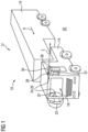
- FIG. 1 shows a perspective illustration of a motor vehicle having a camera monitor system which has a camera arm device with a camera secured thereto;
- FIG. 2 is a plan view of the camera arm device from FIG. 1 in an enlarged illustration and in an operating position;
- FIG. 3 is a cross-sectional view of the camera arm device from FIG. 2 ;
- FIG. 4 is a plan view of the camera arm device from FIG. 1 in an enlarged illustration and in a protected position;
- FIG. 5 is a cross-sectional view of the camera arm device from FIG. 4 ;
- FIG. 6 is a cross-sectional view, oriented perpendicularly to the views in FIG. 3 and FIG. 5 , of the camera arm device from FIG. 1 in different positions.
- FIG. 1 shows a perspective illustration of a motor vehicle 10 , namely a commercial vehicle 12 in the form of a truck, which has a tractor unit 14 and a trailer 16 .
- a driver's cab 18 in which the driver is normally situated during operation of the motor vehicle 10 , wherein the driver is to be able to see as much of the surrounding area 20 as possible during operation of the motor vehicle 10 .
- the driver In particular, he must be able to see fields of vision which are required by law.
- external mirrors 22 are arranged on the tractor unit 14 , by means of which external mirrors the driver is able to see the surrounding area 20 to the rear, that is to say in the direction towards the trailer 16 .
- the motor vehicle 10 has a camera monitor system 24 , which is designed as a mirror replacement system 26 and thus can replace legally required mirrors on the tractor unit 14 .
- the mirror replacement system 26 has a camera arm device 28 which is mounted on the tractor unit 14 outside the driver's cab 18 and which has a camera 30 which records images of the surrounding area 20 of the motor vehicle 10 and forwards them to a monitor 32 which is arranged in the interior of the driver's cab 18 in such a manner that a driver who is in the driver's cab 18 is able to see the images of the camera 30 directly.
- the camera 30 is accordingly secured to the driver's cab 18 via the camera arm device 28 , wherein the camera arm device 28 on the one hand is to perform the function of holding and positioning the camera 30 and additional sensors, and on the other hand includes a function of protecting those elements against external environmental influences such as, for example, collisions.
- One of these protective functions concerns protection against mechanical influences such as forces from a horizontal direction from the front and from the rear and further mechanical impact and shock stresses from all horizontal directions, that is to say from the front, from the rear and from the side.
- FIG. 2 is a plan view of the camera arm device from FIG. 1 in an enlarged illustration and in an operating position B.
- FIG. 3 is a cross-sectional view of the camera arm device 28 from FIG. 2 in the same operating position B.
- the camera arm device 28 has, as can be seen in FIG. 2 and FIG. 3 , a housing 34 which is designed to be hemispherical and hollow, similarly to a shell, and is secured to an outside surface 36 of the motor vehicle 10 .
- a guide groove 38 which is designed as a slot 40 and extends with a concave curvature 42 over a housing surface 44 of the housing 34 .
- the curvature 42 of the guide groove 38 is designed to be concave, but it is also possible to provide other geometries for the guide groove 38 .
- the camera arm device 28 further has a boom element 46 which in the operating position B extends away from the outside surface 36 of the motor vehicle 10 .
- the camera 30 which in the operating position B is able to capture the surrounding area 20 of the motor vehicle 10 in order to display it on the monitor 32 , is arranged on the boom element 46 .
- the boom element 46 is arranged substantially perpendicularly to a direction of travel R of the motor vehicle 10 . It extends away from the outside surface 36 of the motor vehicle 10 in a direction of extension E.
- the boom element 46 is held by the housing 34 , which cooperates with an end portion 48 of the boom element 46 .
- the end portion 48 of the boom element 46 is thereby located inside the housing 34 , while the remainder of the boom element 46 extends through the guide groove 38 out of the housing 34 .
- a positioning device 50 In order to hold the boom element 46 in its operating position B, a positioning device 50 is provided.
- the positioning device has a spring 52 which is fixed on one side to the outside surface 36 of the motor vehicle 10 and is secured on the opposite side to the end portion 48 .
- the boom element 46 is thus pushed away from the outside surface 36 of the motor vehicle 10 by the spring force of the spring 52 .
- Inside the housing 34 there is arranged on the boom element 46 a fall-out prevention device 54 , the circumference U of which is greater than a groove width W of the guide groove 38 .
- the spring 52 thus pushes the fall-out prevention device 54 against the housing 34 from the inside and holds the boom element 46 in the operating position B in the direction of extension E of the boom element 46 .
- the boom element 46 is able to evade the obstacle since it is movably mounted in the guide groove 38 . That is to say, the boom element 46 is not fixed stationarily in the guide groove 38 , or to the housing 34 . If a collision occurs, the boom element 46 moves out of the operating position B and thus prevents excessive forces, which could damage the camera 30 , from acting on the camera 30 .
- the geometry of the guide groove thereby defines the evasion geometry.
- the boom element 46 is able to evade upwards and to the rear until it reaches a protected position S shown in FIG. 4 and FIG. 5 . In this protected position S, the boom element 46 is positioned against the motor vehicle 10 and is protected from mechanical effects.
- a locking device 56 is provided, into which locking device the boom element 46 engages perpendicularly to its direction of extension E.
- the boom element 46 moves along the guide groove 38 , that is to say substantially perpendicularly to a direction of extension E, into the protected position S only when, as a result of a collision, the forces on the boom element 46 overcome the holding force of the locking device 56 .
- the fall-out prevention device 54 is advantageously likewise designed to be hemispherical and has a sphere radius r which corresponds substantially to a sphere radius r of the hemispherical housing 34 .
- the fall-out prevention device 54 is thus able to conform well to the housing 34 from the inside and also slide along the inner surface of the housing 34 when the boom element 46 moves.
- FIG. 2 and FIG. 3 are different views of the boom element 46 in the operating position B, while FIG. 4 and FIG. 5 are different views of the boom element 46 in the protected position S.
- FIG. 6 there is additionally shown a sectional view which is rotated through 90° relative to the views in FIG. 5 and FIG. 3 , wherein the boom element 46 is shown in different positions, namely the operating position B, the protected position S and an intermediate position Z.
Landscapes
- Engineering & Computer Science (AREA)
- Mechanical Engineering (AREA)
- Multimedia (AREA)
- Physics & Mathematics (AREA)
- General Physics & Mathematics (AREA)
- Fittings On The Vehicle Exterior For Carrying Loads, And Devices For Holding Or Mounting Articles (AREA)
- Closed-Circuit Television Systems (AREA)
Abstract
Description
Claims (8)
Applications Claiming Priority (3)
| Application Number | Priority Date | Filing Date | Title |
|---|---|---|---|
| DE102019204418.2A DE102019204418B3 (en) | 2019-03-29 | 2019-03-29 | Camera arm device for a mirror replacement system for a motor vehicle and motor vehicle |
| DE102019204418.2 | 2019-03-29 | ||
| PCT/EP2020/057468 WO2020200790A1 (en) | 2019-03-29 | 2020-03-18 | Camera arm device for a mirror replacement system for a motor vehicle, and motor vehicle |
Publications (2)
| Publication Number | Publication Date |
|---|---|
| US20220176893A1 US20220176893A1 (en) | 2022-06-09 |
| US11958418B2 true US11958418B2 (en) | 2024-04-16 |
Family
ID=69941364
Family Applications (1)
| Application Number | Title | Priority Date | Filing Date |
|---|---|---|---|
| US17/598,171 Active 2040-11-22 US11958418B2 (en) | 2019-03-29 | 2020-03-18 | Camera arm device for a mirror replacement system for a motor vehicle and motor vehicle |
Country Status (4)
| Country | Link |
|---|---|
| US (1) | US11958418B2 (en) |
| JP (1) | JP7314297B2 (en) |
| DE (1) | DE102019204418B3 (en) |
| WO (1) | WO2020200790A1 (en) |
Families Citing this family (2)
| Publication number | Priority date | Publication date | Assignee | Title |
|---|---|---|---|---|
| DE102020121834B3 (en) | 2020-08-20 | 2022-01-20 | Audi Aktiengesellschaft | Sensor arrangement on a vehicle |
| US20240409383A1 (en) | 2023-06-08 | 2024-12-12 | Crown Equipment Corporation | Boom assembly having an adapter |
Citations (21)
| Publication number | Priority date | Publication date | Assignee | Title |
|---|---|---|---|---|
| JPS4716509Y1 (en) | 1969-03-28 | 1972-06-09 | ||
| JPS61502272A (en) | 1984-05-21 | 1986-10-09 | ピ−タ−ソン トム | coupling device |
| JPS63168226U (en) | 1987-04-24 | 1988-11-01 | ||
| JPH0288855U (en) | 1988-12-28 | 1990-07-13 | ||
| US20090231430A1 (en) * | 2006-05-16 | 2009-09-17 | Huf Hülsbeck & Fürst Gmbh & Co. Kg | Device for Capturing an Image of the External Area of a Vehicle by Means of a Camera |
| DE102012201905A1 (en) | 2012-02-09 | 2013-08-14 | Robert Bosch Gmbh | Device for protecting the exterior mirrors of the motor vehicle from colliding with lateral obstacles |
| DE102012015395B3 (en) | 2012-08-03 | 2013-11-28 | Mekra Lang Gmbh & Co. Kg | Camera arm for mirror replacement system camera of motor vehicle, has housing element that is ascertainable relative to another housing element in fixed, non-folded operating position, and pivot mechanism provided between housing elements |
| US20140063233A1 (en) | 2012-08-29 | 2014-03-06 | Smr Patents S.A.R.L. | Side Mirror Assembly with Stationary Camera and Telescoping Mirror Head |
| US20140063245A1 (en) | 2012-08-30 | 2014-03-06 | Nissan North America, Inc. | Vehicle mirror assembly |
| US8896698B2 (en) * | 2010-04-30 | 2014-11-25 | Velvac Incorporated | Front end mounted video camera for vehicle |
| DE102014006961A1 (en) | 2014-05-13 | 2015-11-19 | Man Truck & Bus Ag | Vehicle, in particular commercial vehicle, with a camera-monitor system as a mirror replacement system and method for actuating such a camera-monitor system |
| US20170001578A1 (en) * | 2013-11-27 | 2017-01-05 | Huf Huelsbeck & Fuerst Gmbh & Co. Kg | Motor vehicle camera system |
| US20170280111A1 (en) * | 2011-09-16 | 2017-09-28 | SMR Patents S.à.r.l. | Side Rearview Vision Assembly with Telescoping Head |
| DE102017001122B3 (en) | 2017-02-07 | 2018-02-01 | Audi Ag | motor vehicle |
| US20180265015A1 (en) | 2017-03-16 | 2018-09-20 | Man Truck & Bus Ag | Folding-in device for a mirror replacement system |
| US20180272976A1 (en) | 2017-03-22 | 2018-09-27 | Huf North America Automotive Parts Mfg. Corp. | Sensor system for vehicle closure |
| DE102018205848B3 (en) | 2017-12-22 | 2019-02-14 | Continental Automotive Gmbh | Camera arm of a camera-based mirror replacement system for a motor vehicle |
| US20190176704A1 (en) * | 2016-06-10 | 2019-06-13 | SMR Patents S.à.r.l. | Folding joint for rear view display device |
| US10682965B2 (en) * | 2016-03-24 | 2020-06-16 | Sony Corporation | Imaging unit support apparatus |
| US20210206240A1 (en) * | 2018-06-06 | 2021-07-08 | Volvo Truck Corporation | Vehicle with an external sun visor and a sensor unit connected thereto |
| US20230211740A1 (en) * | 2020-06-24 | 2023-07-06 | Magna Mirrors Of America, Inc. | Vehicular imaging system with extendable camera |
-
2019
- 2019-03-29 DE DE102019204418.2A patent/DE102019204418B3/en active Active
-
2020
- 2020-03-18 WO PCT/EP2020/057468 patent/WO2020200790A1/en not_active Ceased
- 2020-03-18 JP JP2021553867A patent/JP7314297B2/en active Active
- 2020-03-18 US US17/598,171 patent/US11958418B2/en active Active
Patent Citations (23)
| Publication number | Priority date | Publication date | Assignee | Title |
|---|---|---|---|---|
| JPS4716509Y1 (en) | 1969-03-28 | 1972-06-09 | ||
| JPS61502272A (en) | 1984-05-21 | 1986-10-09 | ピ−タ−ソン トム | coupling device |
| US4712814A (en) | 1984-05-21 | 1987-12-15 | Tom Petterson | Coupling arrangement |
| JPS63168226U (en) | 1987-04-24 | 1988-11-01 | ||
| JPH0288855U (en) | 1988-12-28 | 1990-07-13 | ||
| US20090231430A1 (en) * | 2006-05-16 | 2009-09-17 | Huf Hülsbeck & Fürst Gmbh & Co. Kg | Device for Capturing an Image of the External Area of a Vehicle by Means of a Camera |
| US8896698B2 (en) * | 2010-04-30 | 2014-11-25 | Velvac Incorporated | Front end mounted video camera for vehicle |
| US20170280111A1 (en) * | 2011-09-16 | 2017-09-28 | SMR Patents S.à.r.l. | Side Rearview Vision Assembly with Telescoping Head |
| DE102012201905A1 (en) | 2012-02-09 | 2013-08-14 | Robert Bosch Gmbh | Device for protecting the exterior mirrors of the motor vehicle from colliding with lateral obstacles |
| DE102012015395B3 (en) | 2012-08-03 | 2013-11-28 | Mekra Lang Gmbh & Co. Kg | Camera arm for mirror replacement system camera of motor vehicle, has housing element that is ascertainable relative to another housing element in fixed, non-folded operating position, and pivot mechanism provided between housing elements |
| US20140063233A1 (en) | 2012-08-29 | 2014-03-06 | Smr Patents S.A.R.L. | Side Mirror Assembly with Stationary Camera and Telescoping Mirror Head |
| US20140063245A1 (en) | 2012-08-30 | 2014-03-06 | Nissan North America, Inc. | Vehicle mirror assembly |
| US20170001578A1 (en) * | 2013-11-27 | 2017-01-05 | Huf Huelsbeck & Fuerst Gmbh & Co. Kg | Motor vehicle camera system |
| DE102014006961A1 (en) | 2014-05-13 | 2015-11-19 | Man Truck & Bus Ag | Vehicle, in particular commercial vehicle, with a camera-monitor system as a mirror replacement system and method for actuating such a camera-monitor system |
| US10682965B2 (en) * | 2016-03-24 | 2020-06-16 | Sony Corporation | Imaging unit support apparatus |
| US20190176704A1 (en) * | 2016-06-10 | 2019-06-13 | SMR Patents S.à.r.l. | Folding joint for rear view display device |
| DE102017001122B3 (en) | 2017-02-07 | 2018-02-01 | Audi Ag | motor vehicle |
| US20180265015A1 (en) | 2017-03-16 | 2018-09-20 | Man Truck & Bus Ag | Folding-in device for a mirror replacement system |
| US20180272976A1 (en) | 2017-03-22 | 2018-09-27 | Huf North America Automotive Parts Mfg. Corp. | Sensor system for vehicle closure |
| DE102018205848B3 (en) | 2017-12-22 | 2019-02-14 | Continental Automotive Gmbh | Camera arm of a camera-based mirror replacement system for a motor vehicle |
| US20200317142A1 (en) | 2017-12-22 | 2020-10-08 | Continental Automotive Gmbh | Camera arm of a camera-based mirror substitute system for a motor vehicle |
| US20210206240A1 (en) * | 2018-06-06 | 2021-07-08 | Volvo Truck Corporation | Vehicle with an external sun visor and a sensor unit connected thereto |
| US20230211740A1 (en) * | 2020-06-24 | 2023-07-06 | Magna Mirrors Of America, Inc. | Vehicular imaging system with extendable camera |
Non-Patent Citations (5)
| Title |
|---|
| 1 Japanese Decision to Grant dated Jun. 13, 2023 for the Japanese Patent Application No. 2021-553867. |
| International Search Report and Written Opinion dated Apr. 20, 2020 from corresponding International Patent Application No. PCT/EP2020/057468. |
| Notice of Allowance dated Jun. 13, 2023 from corresponding Japanese patent application No. 2021-553867. |
| Notice of Reasons for Refusal dated Aug. 9, 2022 from corresponding Japanese patent application No. 2021-553867. |
| Office Action dated Jan. 10, 2020 from corresponding German Patent Application No. DE 10 2019 204 418.2. |
Also Published As
| Publication number | Publication date |
|---|---|
| JP7314297B2 (en) | 2023-07-25 |
| DE102019204418B3 (en) | 2020-06-18 |
| WO2020200790A1 (en) | 2020-10-08 |
| US20220176893A1 (en) | 2022-06-09 |
| JP2022523862A (en) | 2022-04-26 |
Similar Documents
| Publication | Publication Date | Title |
|---|---|---|
| US10647257B2 (en) | Rear-view sensor system and motor vehicle | |
| US11958418B2 (en) | Camera arm device for a mirror replacement system for a motor vehicle and motor vehicle | |
| KR101552444B1 (en) | Visual system | |
| US12418708B2 (en) | Camera, A-pillar arrangement, and vehicle | |
| KR20150013304A (en) | Reversing Camera Incorporated Into The Logo | |
| KR102457633B1 (en) | Apparatus for real-time road condition check of vehicle front on the right outdoor side | |
| EP4180275A1 (en) | Vehicle front camera arrangement | |
| EP4375141B1 (en) | A camera assembly | |
| US20230111473A1 (en) | Support for a camera display of a vehicle | |
| EP2625069B1 (en) | Rearview mirror with a positioning device for object detection camera | |
| JP2009090767A (en) | Arrangement structure and mounting structure of rear view camera for vehicle | |
| US20150329051A1 (en) | Forward and Rearward Viewing Mirror Device | |
| US20260036888A1 (en) | Motor vehicle with an adjustable camera arranged in the rear region | |
| KR100510268B1 (en) | Side mirror | |
| JP5088635B2 (en) | Reverse mirror | |
| KR101975460B1 (en) | Environment monitoring apparatus for commercial vehicle | |
| KR20170089660A (en) | Back mirror for bicycle | |
| JP6776997B2 (en) | In-vehicle camera | |
| US11797008B2 (en) | Obstacle avoidance system for a camera arm for observing traffic to the rear of a vehicle | |
| KR102771178B1 (en) | Drop prevention structure and rearview device for vehicle including the same | |
| KR20260047706A (en) | Rear camera connection system for yard chassis | |
| KR102088134B1 (en) | Vehicle monitoring system | |
| CN212579745U (en) | Two-section automobile rear-view mirror | |
| JP2023019333A (en) | In-vehicle camera arrangement structure | |
| US20120170145A1 (en) | Mirror assembly for reducing blind spot associated with side view mirrors for vehicles |
Legal Events
| Date | Code | Title | Description |
|---|---|---|---|
| FEPP | Fee payment procedure |
Free format text: ENTITY STATUS SET TO UNDISCOUNTED (ORIGINAL EVENT CODE: BIG.); ENTITY STATUS OF PATENT OWNER: LARGE ENTITY |
|
| AS | Assignment |
Owner name: CONTINENTAL AUTOMOTIVE GMBH, GERMANY Free format text: ASSIGNMENT OF ASSIGNORS INTEREST;ASSIGNOR:PAPE, LUKAS;REEL/FRAME:057604/0782 Effective date: 20210803 |
|
| STPP | Information on status: patent application and granting procedure in general |
Free format text: DOCKETED NEW CASE - READY FOR EXAMINATION |
|
| STPP | Information on status: patent application and granting procedure in general |
Free format text: NON FINAL ACTION MAILED |
|
| STPP | Information on status: patent application and granting procedure in general |
Free format text: RESPONSE TO NON-FINAL OFFICE ACTION ENTERED AND FORWARDED TO EXAMINER |
|
| STPP | Information on status: patent application and granting procedure in general |
Free format text: NOTICE OF ALLOWANCE MAILED -- APPLICATION RECEIVED IN OFFICE OF PUBLICATIONS |
|
| STPP | Information on status: patent application and granting procedure in general |
Free format text: PUBLICATIONS -- ISSUE FEE PAYMENT VERIFIED |
|
| STCF | Information on status: patent grant |
Free format text: PATENTED CASE |
|
| AS | Assignment |
Owner name: CONTINENTAL AUTOMOTIVE TECHNOLOGIES GMBH, GERMANY Free format text: ASSIGNMENT OF ASSIGNORS INTEREST;ASSIGNOR:CONTINENTAL AUTOMOTIVE GMBH;REEL/FRAME:070441/0899 Effective date: 20241211 |