US11955949B2 - Resonator, and filter and duplexer having the same - Google Patents
Resonator, and filter and duplexer having the same Download PDFInfo
- Publication number
- US11955949B2 US11955949B2 US17/320,485 US202117320485A US11955949B2 US 11955949 B2 US11955949 B2 US 11955949B2 US 202117320485 A US202117320485 A US 202117320485A US 11955949 B2 US11955949 B2 US 11955949B2
- Authority
- US
- United States
- Prior art keywords
- protrusion
- protrusions
- resonator
- reference direction
- idt
- Prior art date
- Legal status (The legal status is an assumption and is not a legal conclusion. Google has not performed a legal analysis and makes no representation as to the accuracy of the status listed.)
- Active, expires
Links
- 239000000758 substrate Substances 0.000 claims abstract description 26
- 230000007423 decrease Effects 0.000 claims abstract description 17
- 238000010897 surface acoustic wave method Methods 0.000 description 41
- 238000000034 method Methods 0.000 description 26
- 239000011295 pitch Substances 0.000 description 22
- 108010014173 Factor X Proteins 0.000 description 17
- 230000012447 hatching Effects 0.000 description 7
- 238000004458 analytical method Methods 0.000 description 4
- 230000000694 effects Effects 0.000 description 4
- 230000003247 decreasing effect Effects 0.000 description 3
- 230000005540 biological transmission Effects 0.000 description 2
- 230000015556 catabolic process Effects 0.000 description 2
- 238000006731 degradation reaction Methods 0.000 description 2
- 230000001151 other effect Effects 0.000 description 1
Images


Classifications
-
- H—ELECTRICITY
- H03—ELECTRONIC CIRCUITRY
- H03H—IMPEDANCE NETWORKS, e.g. RESONANT CIRCUITS; RESONATORS
- H03H9/00—Networks comprising electromechanical or electro-acoustic devices; Electromechanical resonators
- H03H9/02—Details
- H03H9/02007—Details of bulk acoustic wave devices
- H03H9/02015—Characteristics of piezoelectric layers, e.g. cutting angles
-
- H—ELECTRICITY
- H03—ELECTRONIC CIRCUITRY
- H03H—IMPEDANCE NETWORKS, e.g. RESONANT CIRCUITS; RESONATORS
- H03H9/00—Networks comprising electromechanical or electro-acoustic devices; Electromechanical resonators
- H03H9/02—Details
- H03H9/125—Driving means, e.g. electrodes, coils
- H03H9/145—Driving means, e.g. electrodes, coils for networks using surface acoustic waves
- H03H9/14544—Transducers of particular shape or position
- H03H9/1457—Transducers having different finger widths
-
- H—ELECTRICITY
- H03—ELECTRONIC CIRCUITRY
- H03H—IMPEDANCE NETWORKS, e.g. RESONANT CIRCUITS; RESONATORS
- H03H9/00—Networks comprising electromechanical or electro-acoustic devices; Electromechanical resonators
- H03H9/02—Details
- H03H9/125—Driving means, e.g. electrodes, coils
- H03H9/145—Driving means, e.g. electrodes, coils for networks using surface acoustic waves
- H03H9/14538—Formation
-
- H—ELECTRICITY
- H03—ELECTRONIC CIRCUITRY
- H03H—IMPEDANCE NETWORKS, e.g. RESONANT CIRCUITS; RESONATORS
- H03H9/00—Networks comprising electromechanical or electro-acoustic devices; Electromechanical resonators
- H03H9/02—Details
- H03H9/125—Driving means, e.g. electrodes, coils
- H03H9/145—Driving means, e.g. electrodes, coils for networks using surface acoustic waves
- H03H9/14544—Transducers of particular shape or position
- H03H9/14576—Transducers whereby only the last fingers have different characteristics with respect to the other fingers, e.g. different shape, thickness or material, split finger
- H03H9/14582—Transducers whereby only the last fingers have different characteristics with respect to the other fingers, e.g. different shape, thickness or material, split finger the last fingers having a different pitch
-
- H—ELECTRICITY
- H03—ELECTRONIC CIRCUITRY
- H03H—IMPEDANCE NETWORKS, e.g. RESONANT CIRCUITS; RESONATORS
- H03H9/00—Networks comprising electromechanical or electro-acoustic devices; Electromechanical resonators
- H03H9/25—Constructional features of resonators using surface acoustic waves
-
- H—ELECTRICITY
- H03—ELECTRONIC CIRCUITRY
- H03H—IMPEDANCE NETWORKS, e.g. RESONANT CIRCUITS; RESONATORS
- H03H9/00—Networks comprising electromechanical or electro-acoustic devices; Electromechanical resonators
- H03H9/46—Filters
- H03H9/64—Filters using surface acoustic waves
-
- H—ELECTRICITY
- H03—ELECTRONIC CIRCUITRY
- H03H—IMPEDANCE NETWORKS, e.g. RESONANT CIRCUITS; RESONATORS
- H03H9/00—Networks comprising electromechanical or electro-acoustic devices; Electromechanical resonators
- H03H9/46—Filters
- H03H9/64—Filters using surface acoustic waves
- H03H9/6423—Means for obtaining a particular transfer characteristic
- H03H9/6433—Coupled resonator filters
- H03H9/6436—Coupled resonator filters having one acoustic track only
-
- H—ELECTRICITY
- H03—ELECTRONIC CIRCUITRY
- H03H—IMPEDANCE NETWORKS, e.g. RESONANT CIRCUITS; RESONATORS
- H03H9/00—Networks comprising electromechanical or electro-acoustic devices; Electromechanical resonators
- H03H9/46—Filters
- H03H9/64—Filters using surface acoustic waves
- H03H9/6423—Means for obtaining a particular transfer characteristic
- H03H9/6433—Coupled resonator filters
- H03H9/6483—Ladder SAW filters
Definitions
- the technique disclosed in this application generally relates to a Surface Acoustic Wave (SAW) resonator and a filter and a duplexer having the resonator.
- SAW Surface Acoustic Wave
- a resonator according to the prior art includes an interdigital transducer (IDT) formed on a substrate, a first reflector formed on the substrate to face one end of the IDT, and a second reflector formed on the substrate to face the other end of the IDT.
- IDT interdigital transducer
- the technique disclosed in this application provides a resonator (surface acoustic wave resonator) with improved performance.
- An object of the present invention to provide a resonator (surface acoustic wave resonator) with improved performance.
- Another object of the present invention is to provide a resonator capable of reducing “Spurious” of a filter.
- Still another object of the present invention is to provide a resonator in which electrostatic discharge (ESD) and power durability characteristics are not degraded.
- ESD electrostatic discharge
- a resonator comprising: an interdigital transducer (IDT) including a first electrode including a first base formed on a piezoelectric substrate and extended in a reference direction, and a plurality of first protrusions connected to the first base and extended in a direction intersecting with the reference direction, and a second electrode including a second base formed on the piezoelectric substrate and extended in the reference direction, and a plurality of second protrusions connected to the second base and extended in a direction intersecting with the reference direction, each of the second protrusions being extended to have any one first protrusion among the plurality of first protrusions inserted between the second protrusion and another second protrusion adjacent to the second protrusion, wherein a width, along the reference direction, of each of a plurality of first specific protrusions included between one end of the IDT and a first position at a first distance from the one end, among the plurality of first protrusion
- IDT interdigital transducer
- the width along the reference direction of each of the first protrusions, among the plurality of first protrusions, excluding the plurality of first specific protrusions is almost the same.
- the width along the reference direction of each of the second protrusions, among the plurality of second protrusions, excluding the plurality of second specific protrusions is almost the same.
- a pitch formed between each of the first protrusions and a first protrusion adjacent to the first protrusion is almost the same, and a pitch formed between each of the second protrusions and a second protrusion adjacent to the second protrusion is almost the same.
- the resonator further comprises: a first reflector formed on the piezoelectric substrate to face the one end of the IDT; and a second reflector formed on the piezoelectric substrate to face the other end of the IDT.
- the piezoelectric substrate is formed of LiTAO 3 or LiNaO 3 .
- the resonator comprises: an interdigital transducer (IDT) including a first electrode including a first base formed on a piezoelectric substrate and extended in a reference direction, and a plurality of first protrusions connected to the first base and extended in a direction intersecting with the reference direction, and a second electrode including a second base formed on the piezoelectric substrate and extended in the reference direction, and a plurality of second protrusions connected to the second base and extended in a direction intersecting with the reference direction, each of the second protrusions being extended to have any one first protrusion among the plurality of first protrusions inserted between the second protrusion and another second protrusion adjacent to the second protrusion, wherein a width, along the reference direction, of each of a plurality of first specific protrusions included between one end of the IDT and a first position at a first distance from the one end, among the plurality of first protrusions and the plurality of second
- FIG. 1 is a mimetic view describing the terms used for a surface acoustic wave (SAW) interdigital transducer (IDT) in this application.
- SAW surface acoustic wave
- IDT interdigital transducer
- FIG. 2 is a mimetic view showing the configuration of a resonator according to a first method.
- FIG. 3 is a graph showing the characteristics of a filter using a resonator according to the first method shown in FIG. 2 .
- FIG. 4 is a mimetic view showing the configuration of a resonator according to a second method.
- FIG. 5 is a graph showing the characteristics of a filter using a resonator according to the second method shown in FIG. 4 .
- FIG. 6 is a mimetic view showing the configuration of a resonator according to an embodiment.
- FIG. 7 is a graph showing the characteristics of a filter using the resonator shown in FIG. 6 compared with the characteristics of filters using resonators applying the first method and the second method.
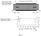
- FIG. 8 is a mimetic view describing a factor for optimizing the characteristics of the resonator according to the embodiment shown in FIG. 6 .
- FIG. 9 is a view showing an experiment result of a first application example of the resonator according to the embodiment shown in FIG. 6 .
- FIG. 10 is a view showing an experiment result of a second application example of the resonator according to the embodiment shown in FIG. 6 .
- FIG. 11 is a view showing an experiment result of a third application example of the resonator according to the embodiment shown in FIG. 6 .
- FIG. 12 is a schematic view showing an example of a filter and a duplexer in which the resonator according to the embodiment shown in FIG. 6 is used.
- FIG. 13 is a schematic view showing another example of a filter and a duplexer in which the resonator according to the embodiment shown in FIG. 6 is used.
- FIG. 1 is a mimetic view describing the terms used for a surface acoustic wave (SAW) interdigital transducer (IDT) in this application.
- SAW surface acoustic wave
- IDT interdigital transducer
- a SAW IDT 10 mainly includes a first electrode 20 and a second electrode 30 .
- the first electrode 20 includes a first base 22 formed on a piezoelectric substrate and extended in a reference direction D 1 , and a plurality of first protrusions 24 ( 24 a , 24 b , 24 c , . . . ) coupled to the first base 22 and extended in a direction intersecting with the reference direction D 1 .
- the second electrode 30 includes a second base 32 formed on the piezoelectric substrate and extended in the reference direction D 1 , and a plurality of second protrusions 34 ( 34 a , 34 b , 34 c , . . . ) coupled to the second base 32 and extended in a direction intersecting with the reference direction D 1 .
- each of the second protrusions 34 is extended to have any one first protrusion 24 , among the plurality of first protrusions 24 , inserted between the second protrusion 34 and another second protrusion 34 adjacent to the second protrusion 34 .
- the second protrusion 34 a is extended to have the first protrusion 24 a inserted between the second protrusion 34 a and another second protrusion 34 b adjacent to the second protrusion 34 a.
- each first protrusion 24 refers to the length of the first protrusion 24 along the reference direction D 1 .
- the width L of each second protrusion 34 refers to the length of the second protrusion 34 along the reference direction D 1 .
- the pitch ⁇ formed between two adjacent first protrusions 24 refers to the distance between the central axis of a first protrusion 24 on one side and the central axis of a first protrusion 24 on the other side.
- the central axis of each first protrusion 24 is extended in a direction perpendicular to the reference direction D 1 .
- the pitch formed between two adjacent second protrusions 34 refers to the distance between the central axis of a second protrusion 34 on one side and the central axis of a second protrusion 34 on the other side.
- the central axis of each second protrusion 34 is extended in a direction perpendicular to the reference direction D 1 .
- L is the width of the target protrusion (first protrusion or second protrusion).
- d is the distance between the target protrusion (first protrusion or second protrusion) and a protrusion adjacent to the target protrusion (when the target protrusion is the first protrusion, the second protrusion adjacent to the first protrusion, and when the target protrusion is the second protrusion, the first protrusion adjacent to the second protrusion).
- d is a distance along the reference direction D 1 of a gap formed between the target protrusion and a protrusion adjacent to the target protrusion.
- FIG. 2 is a mimetic view showing the configuration of a resonator according to a first method.
- the pitch ⁇ formed between two adjacent first protrusions is constant.
- the pitch ⁇ formed between two adjacent second protrusions is also constant.
- the DF of each protrusion included in the plurality of first protrusions and the plurality of second protrusions is also constant.
- FIG. 4 is a mimetic view showing the configuration of a resonator according to a second method.
- the DF of each protrusion included in the plurality of first protrusions and the plurality of second protrusions is constant like the resonator according to the first method.
- the pitch ⁇ formed between two adjacent first protrusions and the pitch ⁇ formed between two adjacent second protrusions gradually decrease toward the end portions.
- the frequency on the reflector side of the resonator changes. Accordingly, as shown in FIG. 5 , in a filter using this resonator, as the “Spurious” generated in the transmission band can be reduced, the characteristics of the resonator can be improved.
- the horizontal axis represents the frequency [MHz]
- the vertical axis represents the gain [dB].
- the dotted line indicates the characteristics of the resonator according to the first method
- the broken line indicates the characteristics of the resonator according to the second method.
- the distance between each first protrusion on the first electrode (e.g., + electrode) and a first protrusion adjacent thereto and the distance between each second protrusion on the second electrode (e.g., ⁇ electrode) and a second protrusion adjacent thereto are reduced. Furthermore, the gap formed between two adjacent protrusions (first protrusion and second protrusion) is reduced. As a result, a problem related to electrostatic discharge (ESD) and power durability may occur.
- ESD electrostatic discharge
- FIG. 6 is a mimetic view showing the configuration of a resonator according to an embodiment of the present invention.
- the resonator 1 shown in FIG. 6 may mainly include a SAW IDT 100 formed on a piezoelectric substrate (not shown), a first reflector 200 formed on the piezoelectric substrate to face one end 100 a of the SAW IDT 100 , and a second reflector 300 formed on the piezoelectric substrate to face the other end 100 b of the SAW IDT 100 .
- the piezoelectric substrate may be formed of, for example, LiTAO 3 or LiNaO 3 .
- the SAW IDT 100 may include a first electrode 120 and a second electrode 130 .
- the first electrode 120 may include a first base 122 formed on the piezoelectric substrate and extended in a reference direction D 1 , and a plurality of first protrusions 124 ( 124 a to 124 f ) coupled to the first base 122 and extended in a direction intersecting with the reference direction D 1 (e.g., perpendicular direction or almost perpendicular direction).
- the first electrode 120 may have a predetermined number of, i.e., seven or more or five or less, first protrusions 124 .
- the second electrode 130 may include a second base 132 formed on the piezoelectric substrate and extended in the reference direction D 1 , and a plurality of second protrusions 134 ( 134 a to 134 g ) coupled to the second base 132 and extended in a direction intersecting with the reference direction D 1 (e.g., perpendicular direction or almost perpendicular direction).
- each of the second protrusions 134 may be extended to have any one first protrusion 124 among the plurality of first protrusions 124 inserted between the second protrusion 134 and another second protrusion 134 adjacent to the second protrusion 134 .
- the second protrusion 134 a may be extended to have the first protrusion 124 a inserted between the second protrusion 134 a and the second protrusion 134 b adjacent to the second protrusion 134 a.
- the second electrode 130 may have a predetermined number of, i.e., eight or more or six or less, second protrusions 134 .
- the pitch ⁇ formed between two adjacent first protrusions 124 may be constant as an example.
- the pitch ⁇ formed between two adjacent second protrusions 134 may be constant also as an example.
- first specific protrusion A plurality of first protrusions 124 and a plurality of second protrusions 134 (hereinafter, referred to as a “first specific protrusion”) are included between this one end 100 a and a first position 100 A at a first distance from this one end 100 a along the reference direction D 1 .
- the first specific protrusion includes a second protrusion 134 c , a first protrusion 124 b , a second protrusion 134 b , a first protrusion 124 a , and a second protrusion 134 a from the first position 100 A toward the one end 100 a.
- the width (length along the reference direction D 1 ) of the plurality of first specific protrusions decreases (gradually decreases for example) from the first specific protrusion 134 c closest to the first position 100 A toward the first specific protrusion 134 a closest to the one end 100 a.
- a plurality of first protrusions 124 and a plurality of second protrusions 134 are included between the other end 100 b and a second position 100 B at a second distance from the other end 100 b along the reference direction D 1 .
- the second specific protrusion includes a second protrusion 134 e , a first protrusion 124 e , a second protrusion 134 f , a first protrusion 124 f , and a second protrusion 134 g from the second position 100 B toward the other end 100 b.
- the width (length along the reference direction D 1 ) of the plurality of second specific protrusions decreases (gradually decreases for example) from the second specific protrusion 134 e closest to the second position 100 B toward the second specific protrusion 134 g closest to the other end 100 b.
- the distance between the one end 100 a and the first position 100 A and the distance between the other end 100 b and the second position 100 B may be set according to the characteristics related to the “Spurious” of the resonator. In addition, the distance between the one end 100 a and the first position 100 A and the distance between the other end 100 b and the second position 100 B may be set to be the same or different.
- the protrusions other than the first specific protrusion and the second specific protrusion may have almost the same width (width along the reference direction D 1 ).
- FIG. 7 is a graph showing the characteristics of a filter using the resonator shown in FIG. 6 compared with the characteristics of filters using resonators applying the first method and the second method.
- the horizontal axis represents the frequency [MHz]
- the vertical axis represents the gain [dB].
- the dotted line indicates the characteristics of a filter using the resonator applying the first method described above
- the broken line indicates the characteristics of a filter using the resonator applying the second method described above
- the solid line indicates the characteristics of a filter using the resonator 1 according to an embodiment of the present invention.
- the width of the first specific protrusion of the SAW IDT 100 is configured to decrease from the first specific protrusion closest to the first position 100 A toward the first specific protrusion closest to one end 100 a
- the width of the second specific protrusion of the SAW IDT 100 is configured to decrease from the second specific protrusion closest to the second position 100 B toward the second specific protrusion closest to the other end 100 b
- the frequency changes between the one end 100 a and the first position 100 A of the SAW IDT 100 and between the other end 100 b and the second position 100 B like the resonator applying the second method. Accordingly, as shown in FIG. 7 , in the filter using the resonator 1 according to an embodiment of the present invention, it is possible to reduce the “Spurious” generated in the band.
- the pitch ⁇ formed between each first protrusion 124 on the first electrode 120 (e.g., + electrode) and a first protrusion 124 adjacent thereto is constant.
- the pitch ⁇ formed between each second protrusion 134 on the second electrode 130 (e.g., ⁇ electrode) and a second protrusion 134 adjacent thereto is also constant. Accordingly, the gap formed between the first protrusion and the second protrusion adjacent to each other increases.
- the pitch ⁇ formed between each first protrusion 124 on the first electrode 120 (e.g., + electrode) and a first protrusion 124 adjacent thereto is also constant.
- the pitch ⁇ formed between each second protrusion 134 on the second electrode 130 (e.g., + electrode) and a second protrusion 134 adjacent thereto is also constant. Accordingly, the gap formed between the first protrusion and the second protrusion adjacent to each other increases. Accordingly, it is possible to suppress degradation of the characteristics related to electrostatic discharge (ESD) and power durability.
- ESD electrostatic discharge
- the “DF Gradation Tap” is the sum of, in the SAW IDT 100 , the number of Taps of all protrusions 124 and 134 existing between one end 100 a and the first position 100 A and the number of Taps of all protrusions 124 and 134 existing between the other end 100 b and the second position 100 B.
- the “Number of Total Taps” is the number of Taps of all protrusions 124 and 134 existing between one end 100 a and the other end 100 b in the SAW IDT 100 .
- Factor Y (Side IDT DF/Main IDT DF) ⁇ 100(%) (2)
- the “Side IDT DF” is the Duty Factor (DF) of each of the protrusions 124 and 134 positioned at one end 100 a and the other end 100 b of the SAW IDT 100 .
- the “Main IDT DF” is the DF of each of the protrusions 124 and 134 positioned between the first position 100 A and the second position 100 B of the SAW IDT 100 .
- factor Y is shown in the lower part of FIG. 8 .
- the DF of each of the other protrusions existing between the first position 100 A and the one end 100 a may be determined, for example, to be approximately inverse-proportional to the distance from the first position 100 A. In this case, two or more adjacent protrusions may have almost the same DF.
- the DF of each of the protrusions between the first position 100 A and the one end 100 a changes in the shape of step since the DF of each protrusion having a constant width along the reference direction D 1 is constant in the width.
- the DF of each of the other protrusions existing between the second position 100 B and the other end 100 b may be determined, for example, to be approximately inverse-proportional to the distance from the second position 100 B. In this case, two or more adjacent protrusions may have almost the same DF.
- the DF of each of the protrusions between the second position 100 B and the other end 100 b changes in the shape of step since the DF of each protrusion having a constant width along the reference direction D 1 is constant in the width.
- FIG. 9 is a view showing an experiment result of a first application example of the resonator according to the embodiment shown in FIG. 6 .
- FIG. 9 shows an experiment result when the resonator according to the embodiment shown in FIG. 6 is applied to a duplexer used for Band1 (1950 MHz).
- the horizontal axis represents factor X (%)
- the vertical axis represents factor Y (%).
- characteristics of “Spurious” the same as those obtained in the case of applying the first method described above are obtained by using a combination of factor X and factor Y corresponding to the white border.
- characteristics of “Spurious” the same as those obtained in the case of applying the second method described above are obtained by using a combination of factor X and factor Y corresponding to the border to which hatching (slash) is applied.
- a characteristic of generating undesirable “Spurious” is obtained by using a combination of factor X and factor Y corresponding to the gray (shaded) border. Accordingly, it can be clearly understood that there is a critical significance in using a combination of factor X and factor Y corresponding to the white border adjacent to the gray border or the border applied with hatching (slash).
- FIG. 10 is a view showing an experiment result of a second application example of the resonator according to the embodiment shown in FIG. 6 .
- FIG. 10 shows an experiment result when the resonator according to the embodiment shown in FIG. 6 is applied to a duplexer used for Band26 (832 MHz).
- the horizontal axis represents factor X (%)
- the vertical axis represents factor Y (%).
- the analysis method of FIG. 10 is the same as the analysis method of FIG. 9 described above. Also, it can be clearly understood that there is a critical significance in using a combination of factor X and factor Y corresponding to the white border adjacent to the gray border or the border applied with hatching.
- FIG. 11 is a view showing an experiment result of a third application example of the resonator according to the embodiment shown in FIG. 6 .
- FIG. 11 shows an experiment result when the resonator according to the embodiment shown in FIG. 6 is applied to a duplexer used for Band1 (2535 MHz).
- the horizontal axis represents factor X (%)
- the vertical axis represents factor Y (%).
- the analysis method of FIG. 11 is also the same as the analysis method of FIG. 9 described above. Also, it can be clearly understood that there is a critical significance in using a combination of factor X and factor Y corresponding to the white border adjacent to the gray border or the border applied with hatching.
- the resonator 1 according to an embodiment of the present invention may be applied to any frequency band other than these.
- the pitches of the first protrusions 124 and the second protrusions 134 included in the SAW IDT may be almost the same. This is since that the problems related to electrostatic discharge (ESD) and power durability can be suppressed to the maximum.
- the pitches of the first protrusions 12 and the second protrusions 13 included in the SAW IDT do not necessarily have to be equal to each other (for example, like the second method described above, the pitches of some of the first protrusions 12 and some of the second protrusions 13 may be changed). Even in this case, it is meaningful in that a characteristic of suppressing occurrence of “Spurious” can be obtained in a resonator and a filter using the resonator.
- the configuration of decreasing the width of each protrusion in this way may also be applied to “any one side” among each of the protrusions existing between the one end 100 a and the first position 100 A of the SAW IDT 100 and each of the protrusions existing between the other end 100 b and the second position 100 B of the SAW IDT 100 .
- the protrusions on the other side may have almost the same width.
- the distance between the one end 100 a and the first position 100 A of the SAW IDT 100 is almost the same as the distance between the other end 100 b and the second position 100 B of the SAW IDT 100 as a preferred embodiment.
- the distance between the one end 100 a and the first position 100 A of the SAW IDT 100 may be different from the distance between the other end 100 b and the second position 100 B of the SAW IDT 100 (e.g., the former distance>the latter distance, or the former distance ⁇ the latter distance).
- the resonator according to the various embodiments described above may be mounted on a SAW filter and a SAW resonator.
- the resonator according to the various embodiments described above is applicable to any SAW resonator (excluding DMS).
- the resonator according to the various embodiments described above is applicable to each resonator 10 included in a filter or a duplexer of a ladder type in which a plurality of resonators is arranged in parallel and in series (or only in parallel or in series).
- the resonator according to the various embodiments described above is applicable to each resonator 10 included in the filter or the duplexer (not applied to DMS90).
- the resonator may be installed such that the width of each protrusion located between one end of the SAW IDT and a first position at a first distance from the one end decreases from the protrusion closest to the first position toward the protrusion closest to the one end.
- it may be installed such that the width of each protrusion located between the other end of the SAW IDT and a second position at a second distance from the other end decreases from the protrusion closest to the second position toward the protrusion closest to the other end. Accordingly, “Spurious” in the characteristics of a resonator and a filter using the resonator may be reduced by changing the frequency between the one end and the first position and/or the frequency between the other end and the second position.
- degradation of the characteristics related to electrostatic discharge (ESD) and power durability may be suppressed by increasing the gap formed between the first protrusion and the second protrusion existing between the one end and the first position to be adjacent to each other and/or by increasing the gap formed between the first protrusion and the second protrusion existing between the other end and the second position to be adjacent to each other.
- the related effect may be more remarkable by making the pitches formed between each first protrusion (each second protrusion) existing between the one end and the other end and a first protrusion (second protrusion) adjacent thereto almost the same.
- a resonator (surface acoustic wave resonator) with improved performance can be provided.
- a resonator with improved performance and a filter and a duplexer having the resonator can be provided.
- a resonator capable of reducing “Spurious” of a filter can be provided.
- a resonator in which electrostatic discharge (ESD) and power durability characteristics are not degraded can be provided.
Landscapes
- Physics & Mathematics (AREA)
- Acoustics & Sound (AREA)
- Surface Acoustic Wave Elements And Circuit Networks Thereof (AREA)
Abstract
Description
DF=L/(L+d)
Factor X: (DF Gradation Tap/Number of Total Taps)×100(%) (1)
Factor Y: (Side IDT DF/Main IDT DF)×100(%) (2)
Claims (6)
Applications Claiming Priority (2)
| Application Number | Priority Date | Filing Date | Title |
|---|---|---|---|
| KR10-2020-0060365 | 2020-05-20 | ||
| KR1020200060365A KR20210143505A (en) | 2020-05-20 | 2020-05-20 | Resonator, filter and duplexer using the resonator |
Publications (2)
| Publication Number | Publication Date |
|---|---|
| US20210367580A1 US20210367580A1 (en) | 2021-11-25 |
| US11955949B2 true US11955949B2 (en) | 2024-04-09 |
Family
ID=78608012
Family Applications (1)
| Application Number | Title | Priority Date | Filing Date |
|---|---|---|---|
| US17/320,485 Active 2042-12-29 US11955949B2 (en) | 2020-05-20 | 2021-05-14 | Resonator, and filter and duplexer having the same |
Country Status (2)
| Country | Link |
|---|---|
| US (1) | US11955949B2 (en) |
| KR (1) | KR20210143505A (en) |
Citations (2)
| Publication number | Priority date | Publication date | Assignee | Title |
|---|---|---|---|---|
| US20110156842A1 (en) * | 2008-09-24 | 2011-06-30 | Murata Manufacturing Co., Ltd. | Elastic wave filter device |
| KR20120114729A (en) | 2011-04-08 | 2012-10-17 | 한국전자통신연구원 | Bandpass filter and electronic device |
-
2020
- 2020-05-20 KR KR1020200060365A patent/KR20210143505A/en active Search and Examination
-
2021
- 2021-05-14 US US17/320,485 patent/US11955949B2/en active Active
Patent Citations (2)
| Publication number | Priority date | Publication date | Assignee | Title |
|---|---|---|---|---|
| US20110156842A1 (en) * | 2008-09-24 | 2011-06-30 | Murata Manufacturing Co., Ltd. | Elastic wave filter device |
| KR20120114729A (en) | 2011-04-08 | 2012-10-17 | 한국전자통신연구원 | Bandpass filter and electronic device |
Also Published As
| Publication number | Publication date |
|---|---|
| KR20210143505A (en) | 2021-11-29 |
| US20210367580A1 (en) | 2021-11-25 |
Similar Documents
| Publication | Publication Date | Title |
|---|---|---|
| US11043933B2 (en) | Notch filter | |
| US8294331B2 (en) | Acoustic wave guide device and method for minimizing trimming effects and piston mode instabilities | |
| US7939989B2 (en) | Piston mode acoustic wave device and method providing a high coupling factor | |
| JP3358615B2 (en) | Vertically coupled resonator type surface acoustic wave filter | |
| US10797679B2 (en) | Elastic wave device | |
| US7679474B2 (en) | Surface acoustic wave resonator, and surface acoustic wave filter | |
| EP1411634B1 (en) | Surface acoustic wave filter | |
| US20140285287A1 (en) | Acoustic wave device | |
| US20060192636A1 (en) | Surface acoustic wave filter | |
| JP4727322B2 (en) | Surface acoustic wave device | |
| US10840881B2 (en) | Longitudinally coupled resonator acoustic wave filter | |
| US11611326B2 (en) | Acoustic wave device and composite filter device | |
| US11018650B2 (en) | Acoustic wave device | |
| JP2007060108A (en) | Surface acoustic wave device | |
| US20220029601A1 (en) | Acoustic wave device | |
| US6552632B2 (en) | Surface acoustic wave resonator with withdrawn electrodes and surface acoustic wave ladder filter using same | |
| US7034634B2 (en) | Surface acoustic wave (SAW) resonator, SAW filter and SAW antenna duplexer using the SAW resonator | |
| US11955949B2 (en) | Resonator, and filter and duplexer having the same | |
| US20150155851A1 (en) | Acoustic wave element | |
| JP2006246510A (en) | Surface wave device | |
| US6005326A (en) | Surface acoustic wave device | |
| JP3915322B2 (en) | Surface acoustic wave filter | |
| US6147574A (en) | Unidirectional surface acoustic wave transducer and transversal-type saw filter having the same | |
| US20020057142A1 (en) | Surface acoustic wave filter | |
| US6781282B1 (en) | Longitudinally coupled resonator-type surface acoustic wave device |
Legal Events
| Date | Code | Title | Description |
|---|---|---|---|
| AS | Assignment |
Owner name: WISOL CO., LTD., KOREA, REPUBLIC OF Free format text: ASSIGNMENT OF ASSIGNORS INTEREST;ASSIGNORS:KAWAMOTO, TOSHIHIKO;SATO, RYOTA;YU, SANG TAI;AND OTHERS;REEL/FRAME:056241/0863 Effective date: 20210511 |
|
| FEPP | Fee payment procedure |
Free format text: ENTITY STATUS SET TO UNDISCOUNTED (ORIGINAL EVENT CODE: BIG.); ENTITY STATUS OF PATENT OWNER: SMALL ENTITY |
|
| STPP | Information on status: patent application and granting procedure in general |
Free format text: DOCKETED NEW CASE - READY FOR EXAMINATION |
|
| FEPP | Fee payment procedure |
Free format text: ENTITY STATUS SET TO SMALL (ORIGINAL EVENT CODE: SMAL); ENTITY STATUS OF PATENT OWNER: SMALL ENTITY |
|
| STPP | Information on status: patent application and granting procedure in general |
Free format text: NOTICE OF ALLOWANCE MAILED -- APPLICATION RECEIVED IN OFFICE OF PUBLICATIONS |
|
| STCF | Information on status: patent grant |
Free format text: PATENTED CASE |