US11944213B1 - Shelving rack with moveable dividers and locking front bar - Google Patents
Shelving rack with moveable dividers and locking front bar Download PDFInfo
- Publication number
- US11944213B1 US11944213B1 US18/524,827 US202318524827A US11944213B1 US 11944213 B1 US11944213 B1 US 11944213B1 US 202318524827 A US202318524827 A US 202318524827A US 11944213 B1 US11944213 B1 US 11944213B1
- Authority
- US
- United States
- Prior art keywords
- wireframe
- divider
- apertures
- support
- shelving rack
- Prior art date
- Legal status (The legal status is an assumption and is not a legal conclusion. Google has not performed a legal analysis and makes no representation as to the accuracy of the status listed.)
- Active
Links
- 210000001364 upper extremity Anatomy 0.000 abstract description 3
- 230000008901 benefit Effects 0.000 description 6
- 235000013361 beverage Nutrition 0.000 description 5
- 235000013305 food Nutrition 0.000 description 3
- 230000004048 modification Effects 0.000 description 1
- 238000012986 modification Methods 0.000 description 1
Images


Classifications
-
- A—HUMAN NECESSITIES
- A47—FURNITURE; DOMESTIC ARTICLES OR APPLIANCES; COFFEE MILLS; SPICE MILLS; SUCTION CLEANERS IN GENERAL
- A47F—SPECIAL FURNITURE, FITTINGS, OR ACCESSORIES FOR SHOPS, STOREHOUSES, BARS, RESTAURANTS OR THE LIKE; PAYING COUNTERS
- A47F5/00—Show stands, hangers, or shelves characterised by their constructional features
- A47F5/0043—Show shelves
- A47F5/005—Partitions therefore
- A47F5/0056—Partitions therefore made of tubes or wire
-
- A—HUMAN NECESSITIES
- A47—FURNITURE; DOMESTIC ARTICLES OR APPLIANCES; COFFEE MILLS; SPICE MILLS; SUCTION CLEANERS IN GENERAL
- A47F—SPECIAL FURNITURE, FITTINGS, OR ACCESSORIES FOR SHOPS, STOREHOUSES, BARS, RESTAURANTS OR THE LIKE; PAYING COUNTERS
- A47F1/00—Racks for dispensing merchandise; Containers for dispensing merchandise
- A47F1/04—Racks or containers with arrangements for dispensing articles, e.g. by means of gravity or springs
- A47F1/12—Racks or containers with arrangements for dispensing articles, e.g. by means of gravity or springs dispensing from the side of an approximately horizontal stack
- A47F1/121—Racks or containers with arrangements for dispensing articles, e.g. by means of gravity or springs dispensing from the side of an approximately horizontal stack made of tubes or wire
-
- A—HUMAN NECESSITIES
- A47—FURNITURE; DOMESTIC ARTICLES OR APPLIANCES; COFFEE MILLS; SPICE MILLS; SUCTION CLEANERS IN GENERAL
- A47F—SPECIAL FURNITURE, FITTINGS, OR ACCESSORIES FOR SHOPS, STOREHOUSES, BARS, RESTAURANTS OR THE LIKE; PAYING COUNTERS
- A47F5/00—Show stands, hangers, or shelves characterised by their constructional features
- A47F5/01—Show stands, hangers, or shelves characterised by their constructional features made of tubes or wire
-
- E—FIXED CONSTRUCTIONS
- E05—LOCKS; KEYS; WINDOW OR DOOR FITTINGS; SAFES
- E05B—LOCKS; ACCESSORIES THEREFOR; HANDCUFFS
- E05B73/00—Devices for locking portable objects against unauthorised removal; Miscellaneous locking devices
-
- E—FIXED CONSTRUCTIONS
- E05—LOCKS; KEYS; WINDOW OR DOOR FITTINGS; SAFES
- E05B—LOCKS; ACCESSORIES THEREFOR; HANDCUFFS
- E05B73/00—Devices for locking portable objects against unauthorised removal; Miscellaneous locking devices
- E05B73/0017—Anti-theft devices, e.g. tags or monitors, fixed to articles, e.g. clothes, and to be removed at the check-out of shops
- E05B73/0023—Containers, boxes, cases or the like, e.g. for compact discs or video-cassettes, specially adapted therefor
-
- A—HUMAN NECESSITIES
- A47—FURNITURE; DOMESTIC ARTICLES OR APPLIANCES; COFFEE MILLS; SPICE MILLS; SUCTION CLEANERS IN GENERAL
- A47B—TABLES; DESKS; OFFICE FURNITURE; CABINETS; DRAWERS; GENERAL DETAILS OF FURNITURE
- A47B73/00—Bottle cupboards; Bottle racks
- A47B73/002—Racks made of wire
-
- A—HUMAN NECESSITIES
- A47—FURNITURE; DOMESTIC ARTICLES OR APPLIANCES; COFFEE MILLS; SPICE MILLS; SUCTION CLEANERS IN GENERAL
- A47F—SPECIAL FURNITURE, FITTINGS, OR ACCESSORIES FOR SHOPS, STOREHOUSES, BARS, RESTAURANTS OR THE LIKE; PAYING COUNTERS
- A47F7/00—Show stands, hangers, or shelves, adapted for particular articles or materials
- A47F7/28—Show stands, hangers, or shelves, adapted for particular articles or materials for containers, e.g. flasks, bottles, tins, milk packs
-
- E—FIXED CONSTRUCTIONS
- E05—LOCKS; KEYS; WINDOW OR DOOR FITTINGS; SAFES
- E05B—LOCKS; ACCESSORIES THEREFOR; HANDCUFFS
- E05B73/00—Devices for locking portable objects against unauthorised removal; Miscellaneous locking devices
- E05B73/0017—Anti-theft devices, e.g. tags or monitors, fixed to articles, e.g. clothes, and to be removed at the check-out of shops
- E05B73/0041—Anti-theft devices, e.g. tags or monitors, fixed to articles, e.g. clothes, and to be removed at the check-out of shops for essentially round objects, e.g. bottles or racket handles
-
- E—FIXED CONSTRUCTIONS
- E05—LOCKS; KEYS; WINDOW OR DOOR FITTINGS; SAFES
- E05B—LOCKS; ACCESSORIES THEREFOR; HANDCUFFS
- E05B73/00—Devices for locking portable objects against unauthorised removal; Miscellaneous locking devices
- E05B73/0017—Anti-theft devices, e.g. tags or monitors, fixed to articles, e.g. clothes, and to be removed at the check-out of shops
- E05B73/0047—Unlocking tools; Decouplers
Definitions
- the present system relates to wire shelving units for dispensing beverages, food products and other items.
- the present system provides a shelving rack system, comprising: a wireframe base; a front divider support extending across a width of the wireframe base; a rear divider support extending across a width of the wireframe base; a wireframe divider that comprises: a front bottom projection receivable into one of a series of apertures in the front divider support, a rear bottom projection receivable into one of a series of apertures in the rear divider support, and a front bracket having at least one aperture passing therethrough; a front stop bar passing through the aperture in the front bracket of the wireframe divider; a locking column at a front of the wireframe base, wherein the front stop bar passes through an aperture in the locking column, and a fastening pin securing the front stop bar within the locking column.
- the wireframe divider is positioned and then locked into position by first pulling the divider forwards such that the rear hook locks in position in the rear divider support. Next, the wireframe divider is rotated downwardly such that its front leg locks into position.
- This locking motion is both quick and easy for the operator standing at the front of the shelving unit. As such, the operator does not need to fumble around with structures in the back of the shelving rack system. Rather, the positioning and re-positioning and locking of the divider can be done while only holding onto the front portions of the wireframe divider.
- a front stop bar is inserted through aligned apertures on a front bracket on the wireframe divider(s), the locking column on one front side of the wireframe base and a side support column on an opposite front side of the wireframe base.
- a fastening pin can be inserted downwardly into the locking column to secure the front stop bar into a locked position.
- the fastening pin holds the front stop bar in a locked position which in turn holds the wireframe divider in its locked position.
- the rear bottom projection on the wireframe divider is a hook that is simply pulled forwards to latch into one of the apertures in the rear divider support.
- the front bottom projection (which is preferably a leg post) is inserted downwardly into one of the apertures in the front divider support after the hook has been pulled forwards to latch into one of the apertures of the rear divider support.
- the wireframe base also comprises a front panel, and the front bracket rests upon the front panel after the front bottom projection has been inserted down into one of the apertures in the front divider support.
- the wireframe divider is moveable across a width of the wireframe base by simply repositioning the front and rear bottom projections within various apertures in the front and rear divider supports. It is to be understood that although only one wireframe divider is described herein, multiple wireframe dividers can be positioned in parallel across the surface of the wireframe base within the present shelving rack.
- the locking column has a pair of apertures to receive the fastening pin therethrough, and the fastening pin also passes vertically down through an aperture in the front stop bar.
- the locking column has a series of apertures passing therethrough that align with a series of apertures in the front bracket of the wireframe divider.
- a plurality of apertures at the same heights are preferably included on each of the wireframe divider's front bracket, and on a side support column positioned on an opposite front side of the wireframe shelf.
- the front support bar can be positioned at different vertical heights as desired, or a plurality of different front support bars can be used simultaneously, each positioned at different heights.
- a first advantage of the present system is that the front stop bar can be positioned at an adjustable height (such that different heights may be used to dispense beverages or other products of different heights).
- a second advantage of the present system is that it provides a compact, convenient and easy to use system for locking the front stop bar into position.
- a third advantage of the present system is that it can provide multiple front stop bars at different heights as desired.
- a fourth advantage of the present system is that it provides a novel locking system for positioning the rear end of the divider into a locked position quickly and easily. Lastly, all of this can be done by an operator standing at the front of the shelving unit, without having to reach far back into the shelving unit.
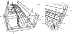
- FIG. 1 is a front perspective view of the wireframe shelving rack, using one front stop bar.
- FIG. 2 is a top perspective view of the present wireframe shelving rack, with the wireframe divider removed.
- FIG. 3 is a side elevation view of one of the dividers.
- FIG. 4 is a front perspective view of the present wireframe shelving rack, showing operation of the locking column.
- FIG. 5 is a front perspective view of the present wireframe shelving rack, instead using a plurality of front stop bars.
- FIG. 6 is a front perspective view of the wireframe shelving rack, using a somewhat larger diameter front support bar.
- FIG. 7 is a front perspective view of the present wireframe shelving rack, showing operation of the locking column with the larger diameter front support bar of FIG. 6 .
- FIG. 8 is a perspective view of the rear area of the present wireframe shelving rack, showing the rear bottom projection (e.g.: a hook) on the divider about to be positioned in one of the apertures of the rear divider support.
- the rear bottom projection e.g.: a hook
- FIG. 9 is a perspective view of the front area of the present wireframe shelving rack, showing the front bottom projection (e.g.: a leg post) on the divider about to be positioned in one of the apertures of the front divider support.
- the front bottom projection e.g.: a leg post
- FIG. 10 is a perspective view of the front area of the present wireframe shelving rack, showing the front bottom projection (e.g.: leg) on the divider after it has been positioned in one of the apertures of the front divider support, with the front bracket of the wireframe divider positioned on top of a front panel of the wireframe shelving rack.
- the front bottom projection e.g.: leg
- FIG. 1 is a front perspective view of the wireframe shelving rack 10 , having a moveable (side-to-side) wireframe divider 20 with one front stop bar 30 .
- FIG. 2 is a top perspective view of the present wireframe shelving rack 10 , with the wireframe divider removed.
- FIG. 3 is a side elevation view of one of the wireframe dividers 20 .
- the present system provides a shelving rack system 10 , comprising: a wireframe base 21 ; a front divider support 22 extending across a width of wireframe base 21 ; a rear divider support 24 extending across a width of wireframe base 21 ; and a wireframe divider 20 .
- the wireframe divider 20 includes: a front bottom projection 25 receivable into one of a series of apertures 23 in the front divider support 22 , a rear bottom projection 29 receivable into one of a series of apertures 26 in the rear divider support 24 , and a front bracket 40 having at least one aperture 42 passing therethrough.
- the front stop bar 30 passes through the aperture 42 in front bracket 40 of wireframe divider 20 .
- a locking column 50 is also provided at a front of wireframe base 21 .
- front stop bar 30 passes though one of the apertures 52 in locking column 50 .
- a fastening pin 60 secures the front stop bar 30 within the locking column 50 .
- FIG. 4 is a front perspective view of the present wireframe shelving rack, showing operation of the locking column 50 .
- fastening pin 60 is simply inserted vertically downwards through top and bottom apertures 53 in locking column 50 , while also passing through an aperture 31 in front stop bar 30 .
- FIG. 5 is a front perspective view of the present wireframe shelving rack 10 , instead using a plurality of front stop bars 30 A, 30 B and 30 C. In this embodiment, each of the three front stop bars 30 A, 30 B and 30 C can all be locked into position by downwardly inserted fastening pin 60 .
- FIG. 6 is a front perspective view of the wireframe shelving rack, using a somewhat larger diameter front support bar 30 (as compared to the front support bars 30 A, 30 B and 30 C in FIG. 4 ).
- FIG. 7 illustrates operation of the present locking column 50 .
- FIGS. 8 , 9 and 10 The easy and rapid locking feature of the present system is best understood by viewing FIGS. 8 , 9 and 10 in sequence, as follows.
- FIG. 8 which shows a rear portion of the wireframe shelf
- the operator is about to insert hook 29 into one of the apertures 26 in rear divider support 24 .
- having the apertures 26 positioned generally vertical as shown enables hook 29 to be quickly inserted into one of these apertures, and then pulled forwards, thereby securing hook 29 into one of apertures 26 .
- wireframe divider 20 is pulled forwards (to then position front bottom projection (e.g.: leg 25 ) on the wireframe divider 20 downwardly into one of the apertures 23 of front divider support 22 .
- FIG. 9 shows a rear portion of the wireframe shelf
- FIG. 10 shows the front bottom projection (leg 25 ) after it has been positioned down into one of the apertures 23 of front divider support 22 . At this time, the position of leg 25 within aperture 23 will prevent hook 29 from coming loose from its position within aperture 26 . Thus, the wireframe divider 20 will be locked into position.
- the front bracket 40 of wireframe divider 20 is preferably positioned to rest on top of a front panel 27 of wireframe shelving rack 10 .
- a side support column 70 is preferably positioned on an opposite front side of the wireframe base from locking column 60 .
- Side support column 70 preferably also has a series of apertures 72 passing therethrough.
- apertures 72 , 42 and 52 are all aligned with one another. Therefore, once hook 29 has been locked forward into one of apertures 26 , followed by leg 25 locked down into one of apertures 23 , front support bar 30 can then be passed through apertures 72 , 42 and 52 (thereby preventing leg 25 from being lifted out of its selected aperture 23 ). Finally, by inserting fastening pin 60 down into locking column 50 , front stop bar(s) 30 can itself be secured into a locked position.
- fastening pin 60 is removed, followed by front stop bar 30 being removed, followed by lifting the front end of wireframe divider 20 such that leg 25 is removed from its selected aperture 23 so that the wireframe divider 20 can be gently slid backwards to remove hook 29 from aperture 26 , thus freeing the wireframe divider.
- a new position is then selected for the wireframe divider with rear hook 29 inserted into a new rear aperture 26 , followed by leg 25 lowered into a new aperture 23 .
- a support panel (not shown) may be positioned on top of the wireframe base, having holes through which hook 29 and leg 25 may be inserted through down into rear divider support 24 and front divider support 22 , respectively.
- a back support (such as a bar or one or more wires) may span across the back of the shelving rack, thereby providing a back support to beverages and food products sitting in the shelving rack.
Abstract
A shelving rack system with a wireframe base and at least one wireframe divider having a rear hook that is received into an aperture on a rear support and a front leg that is received down into an aperture on a front support. The divider is locked into position by first pulling the divider forwards such that the rear hook locks in position and then rotating the divider downwards such that front leg locks into position. Next, a front stop bar is inserted through aligned apertures on a front bracket on the divider, a locking column on one side of the wireframe base and a side support column on an opposite side of the wireframe base. Finally, a fastening pin is inserted down into the locking column to secure the front stop bar into a locked position.
Description
The present system relates to wire shelving units for dispensing beverages, food products and other items.
The present inventors have previously developed wireframe shelving systems for dispensing beverages and food products from refrigerated store cabinets. Examples of such systems are seen in U.S. Pat. Nos. 10,463,172 and 10,405,673, both entitled “Shelving Rack Having Bottom Support Panel with Moveable Dividers”.
Although these existing systems have proven to be excellent in operation, the Applicants desire to provide wireframe shelving units having additional non-obvious features and modifications, including for example, faster and easier locking of the wireframe divider into position, and providing an adjustable-height front stop bar. As will be shown herein, the present system provides such an improved system with such advantages, and provides additional benefits.
In preferred aspects, the present system provides a shelving rack system, comprising: a wireframe base; a front divider support extending across a width of the wireframe base; a rear divider support extending across a width of the wireframe base; a wireframe divider that comprises: a front bottom projection receivable into one of a series of apertures in the front divider support, a rear bottom projection receivable into one of a series of apertures in the rear divider support, and a front bracket having at least one aperture passing therethrough; a front stop bar passing through the aperture in the front bracket of the wireframe divider; a locking column at a front of the wireframe base, wherein the front stop bar passes through an aperture in the locking column, and a fastening pin securing the front stop bar within the locking column.
In operation, the wireframe divider is positioned and then locked into position by first pulling the divider forwards such that the rear hook locks in position in the rear divider support. Next, the wireframe divider is rotated downwardly such that its front leg locks into position. This locking motion is both quick and easy for the operator standing at the front of the shelving unit. As such, the operator does not need to fumble around with structures in the back of the shelving rack system. Rather, the positioning and re-positioning and locking of the divider can be done while only holding onto the front portions of the wireframe divider. Next, after the wireframe divider has been positioned, a front stop bar is inserted through aligned apertures on a front bracket on the wireframe divider(s), the locking column on one front side of the wireframe base and a side support column on an opposite front side of the wireframe base. Finally, a fastening pin can be inserted downwardly into the locking column to secure the front stop bar into a locked position. Advantageously, the fastening pin holds the front stop bar in a locked position which in turn holds the wireframe divider in its locked position.
In preferred embodiments, the rear bottom projection on the wireframe divider is a hook that is simply pulled forwards to latch into one of the apertures in the rear divider support. Next, the front bottom projection (which is preferably a leg post) is inserted downwardly into one of the apertures in the front divider support after the hook has been pulled forwards to latch into one of the apertures of the rear divider support.
In preferred embodiments, the wireframe base also comprises a front panel, and the front bracket rests upon the front panel after the front bottom projection has been inserted down into one of the apertures in the front divider support.
In operation, the wireframe divider is moveable across a width of the wireframe base by simply repositioning the front and rear bottom projections within various apertures in the front and rear divider supports. It is to be understood that although only one wireframe divider is described herein, multiple wireframe dividers can be positioned in parallel across the surface of the wireframe base within the present shelving rack.
In preferred aspects, the locking column has a pair of apertures to receive the fastening pin therethrough, and the fastening pin also passes vertically down through an aperture in the front stop bar. Also in preferred aspects, the locking column has a series of apertures passing therethrough that align with a series of apertures in the front bracket of the wireframe divider. A plurality of apertures at the same heights are preferably included on each of the wireframe divider's front bracket, and on a side support column positioned on an opposite front side of the wireframe shelf. As such, the front support bar can be positioned at different vertical heights as desired, or a plurality of different front support bars can be used simultaneously, each positioned at different heights.
In short, a first advantage of the present system is that the front stop bar can be positioned at an adjustable height (such that different heights may be used to dispense beverages or other products of different heights). A second advantage of the present system is that it provides a compact, convenient and easy to use system for locking the front stop bar into position. A third advantage of the present system is that it can provide multiple front stop bars at different heights as desired. A fourth advantage of the present system is that it provides a novel locking system for positioning the rear end of the divider into a locked position quickly and easily. Lastly, all of this can be done by an operator standing at the front of the shelving unit, without having to reach far back into the shelving unit.
As seen in the attached Figures, the present system provides a shelving rack system 10, comprising: a wireframe base 21; a front divider support 22 extending across a width of wireframe base 21; a rear divider support 24 extending across a width of wireframe base 21; and a wireframe divider 20.
In preferred aspects, the wireframe divider 20, includes: a front bottom projection 25 receivable into one of a series of apertures 23 in the front divider support 22, a rear bottom projection 29 receivable into one of a series of apertures 26 in the rear divider support 24, and a front bracket 40 having at least one aperture 42 passing therethrough.
The front stop bar 30 passes through the aperture 42 in front bracket 40 of wireframe divider 20. A locking column 50 is also provided at a front of wireframe base 21. As can be seen, front stop bar 30 passes though one of the apertures 52 in locking column 50. Finally, a fastening pin 60 secures the front stop bar 30 within the locking column 50.
The easy and rapid locking feature of the present system is best understood by viewing FIGS. 8, 9 and 10 in sequence, as follows. First, in FIG. 8 (which shows a rear portion of the wireframe shelf), the operator is about to insert hook 29 into one of the apertures 26 in rear divider support 24. As can be appreciated, having the apertures 26 positioned generally vertical as shown enables hook 29 to be quickly inserted into one of these apertures, and then pulled forwards, thereby securing hook 29 into one of apertures 26. Next, as seen in FIG. 9 , wireframe divider 20 is pulled forwards (to then position front bottom projection (e.g.: leg 25) on the wireframe divider 20 downwardly into one of the apertures 23 of front divider support 22. Lastly, FIG. 10 shows the front bottom projection (leg 25) after it has been positioned down into one of the apertures 23 of front divider support 22. At this time, the position of leg 25 within aperture 23 will prevent hook 29 from coming loose from its position within aperture 26. Thus, the wireframe divider 20 will be locked into position. In addition, as can also be seen in FIG. 10 , the front bracket 40 of wireframe divider 20 is preferably positioned to rest on top of a front panel 27 of wireframe shelving rack 10.
As can be seen in FIGS. 1, 4 and 7 , a side support column 70 is preferably positioned on an opposite front side of the wireframe base from locking column 60. Side support column 70 preferably also has a series of apertures 72 passing therethrough. In preferred aspects, apertures 72, 42 and 52 are all aligned with one another. Therefore, once hook 29 has been locked forward into one of apertures 26, followed by leg 25 locked down into one of apertures 23, front support bar 30 can then be passed through apertures 72, 42 and 52 (thereby preventing leg 25 from being lifted out of its selected aperture 23). Finally, by inserting fastening pin 60 down into locking column 50, front stop bar(s) 30 can itself be secured into a locked position.
To move wireframe divider to a new position (for example when dispensing a new beverage or product of a different width), fastening pin 60 is removed, followed by front stop bar 30 being removed, followed by lifting the front end of wireframe divider 20 such that leg 25 is removed from its selected aperture 23 so that the wireframe divider 20 can be gently slid backwards to remove hook 29 from aperture 26, thus freeing the wireframe divider. A new position is then selected for the wireframe divider with rear hook 29 inserted into a new rear aperture 26, followed by leg 25 lowered into a new aperture 23. Once again, re-inserting front stop bar 30 through apertures 52, 42 and 72 will again lock the wireframe divider 20 into its new position, and then fastening pin 60 then prevents front stop bar 30 from moving.
In optional embodiments, a support panel (not shown) may be positioned on top of the wireframe base, having holes through which hook 29 and leg 25 may be inserted through down into rear divider support 24 and front divider support 22, respectively. In other optional embodiments, a back support (such as a bar or one or more wires) may span across the back of the shelving rack, thereby providing a back support to beverages and food products sitting in the shelving rack.
Claims (11)
1. A shelving rack system, comprising:
a wireframe base;
a front divider support extending across a width of the wireframe base;
a rear divider support extending across a width of the wireframe base;
a wireframe divider, wherein the wireframe divider comprises:
a front bottom projection receivable into one of a series of apertures in the front divider support,
a rear bottom projection receivable into one of a series of apertures in the rear divider support, and
a front bracket having at least one aperture therethrough;
a front stop bar that passes through the at least one aperture in the front bracket of the wireframe divider;
a locking column at a front of the wireframe base, wherein the front stop bar passes through an aperture in the locking column, and
a fastening pin configured to secure the front stop bar within the locking column.
2. The shelving rack system of claim 1 , wherein the rear bottom projection on the wireframe divider is a hook.
3. The shelving rack of claim 2 , wherein the hook is configured to be pulled forwards to latch into one of the apertures in the rear divider support.
4. The shelving rack of claim 3 , wherein the front bottom projection is configured to be inserted down into one of the apertures in the front divider support after the hook has been pulled forwards to latch into one of the apertures of the rear divider support.
5. The shelving rack of claim 1 , wherein the wireframe base further comprises a front panel, and wherein the front bracket is configured to rest upon the front panel when the front bottom projection is inserted down into one of the apertures in the front divider support.
6. The shelving rack of claim 1 , wherein the wireframe divider is moveable across a width of the wireframe base by repositioning the front and rear bottom projections within various apertures from said series of apertures in the front and rear divider supports.
7. The shelving rack of claim 1 , wherein the locking column has a pair of apertures to receive the fastening pin therethrough, and wherein the fastening pin also passes through an aperture in the front stop bar.
8. The shelving rack of claim 7 , wherein fastening pin is configured to be inserted vertically down into the locking column.
9. The shelving rack of claim 1 , wherein the locking column has a series of apertures passing therethrough that align with a series of apertures from the at least one aperture of the front bracket.
10. The shelving rack of claim 9 , further comprising:
a side support column positioned on an opposite front side of the wireframe base from the locking column, the side support column having a series of apertures passing therethrough that align both with the series of apertures in the front bracket and with the series of apertures in the locking column.
11. The shelving rack of claim 10 , wherein the front stop bar passes through a corresponding aperture in each of the locking column, the front bracket in the wireframe divider and the side support column respectively.
Priority Applications (1)
| Application Number | Priority Date | Filing Date | Title |
|---|---|---|---|
| US18/524,827 US11944213B1 (en) | 2023-11-30 | 2023-11-30 | Shelving rack with moveable dividers and locking front bar |
Applications Claiming Priority (1)
| Application Number | Priority Date | Filing Date | Title |
|---|---|---|---|
| US18/524,827 US11944213B1 (en) | 2023-11-30 | 2023-11-30 | Shelving rack with moveable dividers and locking front bar |
Publications (1)
| Publication Number | Publication Date |
|---|---|
| US11944213B1 true US11944213B1 (en) | 2024-04-02 |
Family
ID=90472048
Family Applications (1)
| Application Number | Title | Priority Date | Filing Date |
|---|---|---|---|
| US18/524,827 Active US11944213B1 (en) | 2023-11-30 | 2023-11-30 | Shelving rack with moveable dividers and locking front bar |
Country Status (1)
| Country | Link |
|---|---|
| US (1) | US11944213B1 (en) |
Citations (39)
| Publication number | Priority date | Publication date | Assignee | Title |
|---|---|---|---|---|
| US2933195A (en) * | 1955-11-30 | 1960-04-19 | Radek John | Shelves and adjustable partitions therefor |
| US3015399A (en) * | 1959-08-07 | 1962-01-02 | Ready Metal Mfg Co | Merchandise display equipment |
| US3110402A (en) * | 1961-03-29 | 1963-11-12 | Cons Cigar Corp | Adjustable display rack |
| US3149729A (en) * | 1962-12-31 | 1964-09-22 | Banner Metals Inc | Display rack |
| US3194528A (en) * | 1963-06-03 | 1965-07-13 | Chesley Ind Inc | Shelf structure |
| US3385451A (en) * | 1966-06-23 | 1968-05-28 | New London Mills Inc | Display fixture |
| US3501020A (en) * | 1967-12-27 | 1970-03-17 | George Krikorian | Bin construction |
| US3608741A (en) * | 1970-05-27 | 1971-09-28 | United Steel & Wire Co | Shelf partition |
| US4036366A (en) * | 1976-03-17 | 1977-07-19 | Kaiser Aluminum & Chemical Corporation | Storage rack and hanger assembly |
| US4190167A (en) * | 1978-05-25 | 1980-02-26 | Kinda Frank L | Adjustable wire divider |
| USRE30706E (en) * | 1979-06-13 | 1981-08-11 | Leggett & Platt, Incorporated | Display rack with improved shelf assembly |
| US4346806A (en) * | 1980-03-11 | 1982-08-31 | Leggett & Platt, Incorporated | Shelf organizer |
| US4359947A (en) * | 1980-03-10 | 1982-11-23 | Marschak Howard J | Shelving assembly |
| US4562927A (en) * | 1983-05-06 | 1986-01-07 | Cornelius Cannon Inc. | Display rack |
| US4872567A (en) * | 1986-05-23 | 1989-10-10 | Leggett & Platt, Incorporated | Shelf conversion unit for gondola display |
| US5119945A (en) * | 1990-10-24 | 1992-06-09 | L&P Property Management Company | Gondola display with improved display rack and rack lock |
| US5205421A (en) * | 1991-04-01 | 1993-04-27 | Leggett & Platt, Incorporated | Gondola display rack |
| US5450971A (en) * | 1994-10-11 | 1995-09-19 | Paul Flum Ideas, Inc. | Adjustable shelf support structure |
| US5520291A (en) * | 1994-07-27 | 1996-05-28 | Graham; Don S. | Partitioned locking rack |
| US6116436A (en) * | 1998-09-18 | 2000-09-12 | Metro Industries, Inc. | Modular shelving storage system |
| US6302036B1 (en) * | 1998-06-22 | 2001-10-16 | Anthony, Inc. | Shelving system, shelf support, and shelf |
| US20010045403A1 (en) * | 1997-10-01 | 2001-11-29 | Display Industries | Display shelf insert having anti-rotation means |
| US20020033373A1 (en) * | 1997-10-01 | 2002-03-21 | Robertson James David | Display shelf having anti-rotation means |
| US6526897B1 (en) * | 2000-09-21 | 2003-03-04 | V. John Ondrasik | Shelving system |
| US20040011754A1 (en) * | 2002-07-18 | 2004-01-22 | Southern Imperial, Inc. | Telescoping shelf divider |
| US6767234B1 (en) * | 2001-02-14 | 2004-07-27 | P.O.P. Displays, Inc. | Hook and hang display system with plug-in bullnose header module |
| US7104094B2 (en) * | 2003-09-16 | 2006-09-12 | Southern Imperial, Inc. | Merchandise lock bar system and method |
| US20080314846A1 (en) * | 2007-06-21 | 2008-12-25 | Klein Richard B | Storage rack for pot and pan lids |
| US20100200526A1 (en) * | 2009-02-11 | 2010-08-12 | Southern Imperial, Inc. | Self Contained Retail Pusher |
| US20120217212A1 (en) * | 2011-02-24 | 2012-08-30 | E-B Display Company, Inc. | Display assembly with integral roller base |
| US20140217042A1 (en) * | 2005-09-12 | 2014-08-07 | Rtc Industries, Inc. | Product management display system |
| US20140319087A1 (en) * | 2013-04-30 | 2014-10-30 | The Marco Company | Freezer Pusher |
| US20150023727A1 (en) * | 2013-07-16 | 2015-01-22 | Fasteners For Retail, Inc. | Lock for securing front rail to wire shelving |
| US20150114918A1 (en) * | 2012-12-07 | 2015-04-30 | The Marco Company | Roller shelf |
| US9351590B1 (en) * | 2015-07-31 | 2016-05-31 | Trion Industries, Inc. | Adjustable depth wire divider for gondola shelving |
| US10405673B1 (en) * | 2018-05-14 | 2019-09-10 | The Ondrasik Family Trust Dated 11/3/1999 | Shelving rack having bottom support panel with moveable dividers |
| US10660435B2 (en) * | 2018-02-08 | 2020-05-26 | Sungal Corporation | In-door cooler rack shelving system |
| US20210339910A1 (en) * | 2020-04-29 | 2021-11-04 | Eric Schuldt | Inventory management system |
| US20220007855A1 (en) * | 2020-07-09 | 2022-01-13 | Logiquip Llc | Clip-on adaptor for inventory divider |
-
2023
- 2023-11-30 US US18/524,827 patent/US11944213B1/en active Active
Patent Citations (40)
| Publication number | Priority date | Publication date | Assignee | Title |
|---|---|---|---|---|
| US2933195A (en) * | 1955-11-30 | 1960-04-19 | Radek John | Shelves and adjustable partitions therefor |
| US3015399A (en) * | 1959-08-07 | 1962-01-02 | Ready Metal Mfg Co | Merchandise display equipment |
| US3110402A (en) * | 1961-03-29 | 1963-11-12 | Cons Cigar Corp | Adjustable display rack |
| US3149729A (en) * | 1962-12-31 | 1964-09-22 | Banner Metals Inc | Display rack |
| US3194528A (en) * | 1963-06-03 | 1965-07-13 | Chesley Ind Inc | Shelf structure |
| US3385451A (en) * | 1966-06-23 | 1968-05-28 | New London Mills Inc | Display fixture |
| US3501020A (en) * | 1967-12-27 | 1970-03-17 | George Krikorian | Bin construction |
| US3608741A (en) * | 1970-05-27 | 1971-09-28 | United Steel & Wire Co | Shelf partition |
| US4036366A (en) * | 1976-03-17 | 1977-07-19 | Kaiser Aluminum & Chemical Corporation | Storage rack and hanger assembly |
| US4190167A (en) * | 1978-05-25 | 1980-02-26 | Kinda Frank L | Adjustable wire divider |
| USRE30706E (en) * | 1979-06-13 | 1981-08-11 | Leggett & Platt, Incorporated | Display rack with improved shelf assembly |
| US4359947A (en) * | 1980-03-10 | 1982-11-23 | Marschak Howard J | Shelving assembly |
| US4346806A (en) * | 1980-03-11 | 1982-08-31 | Leggett & Platt, Incorporated | Shelf organizer |
| US4562927A (en) * | 1983-05-06 | 1986-01-07 | Cornelius Cannon Inc. | Display rack |
| US4872567A (en) * | 1986-05-23 | 1989-10-10 | Leggett & Platt, Incorporated | Shelf conversion unit for gondola display |
| US5119945A (en) * | 1990-10-24 | 1992-06-09 | L&P Property Management Company | Gondola display with improved display rack and rack lock |
| US5205421A (en) * | 1991-04-01 | 1993-04-27 | Leggett & Platt, Incorporated | Gondola display rack |
| US5520291A (en) * | 1994-07-27 | 1996-05-28 | Graham; Don S. | Partitioned locking rack |
| US5450971A (en) * | 1994-10-11 | 1995-09-19 | Paul Flum Ideas, Inc. | Adjustable shelf support structure |
| US20020033373A1 (en) * | 1997-10-01 | 2002-03-21 | Robertson James David | Display shelf having anti-rotation means |
| US20010045403A1 (en) * | 1997-10-01 | 2001-11-29 | Display Industries | Display shelf insert having anti-rotation means |
| US6302036B1 (en) * | 1998-06-22 | 2001-10-16 | Anthony, Inc. | Shelving system, shelf support, and shelf |
| US6116436A (en) * | 1998-09-18 | 2000-09-12 | Metro Industries, Inc. | Modular shelving storage system |
| US6526897B1 (en) * | 2000-09-21 | 2003-03-04 | V. John Ondrasik | Shelving system |
| US6767234B1 (en) * | 2001-02-14 | 2004-07-27 | P.O.P. Displays, Inc. | Hook and hang display system with plug-in bullnose header module |
| US20040011754A1 (en) * | 2002-07-18 | 2004-01-22 | Southern Imperial, Inc. | Telescoping shelf divider |
| US7104094B2 (en) * | 2003-09-16 | 2006-09-12 | Southern Imperial, Inc. | Merchandise lock bar system and method |
| US20140217042A1 (en) * | 2005-09-12 | 2014-08-07 | Rtc Industries, Inc. | Product management display system |
| US20080314846A1 (en) * | 2007-06-21 | 2008-12-25 | Klein Richard B | Storage rack for pot and pan lids |
| US20100200526A1 (en) * | 2009-02-11 | 2010-08-12 | Southern Imperial, Inc. | Self Contained Retail Pusher |
| US20120217212A1 (en) * | 2011-02-24 | 2012-08-30 | E-B Display Company, Inc. | Display assembly with integral roller base |
| US20150114918A1 (en) * | 2012-12-07 | 2015-04-30 | The Marco Company | Roller shelf |
| US20140319087A1 (en) * | 2013-04-30 | 2014-10-30 | The Marco Company | Freezer Pusher |
| US20150023727A1 (en) * | 2013-07-16 | 2015-01-22 | Fasteners For Retail, Inc. | Lock for securing front rail to wire shelving |
| US9351590B1 (en) * | 2015-07-31 | 2016-05-31 | Trion Industries, Inc. | Adjustable depth wire divider for gondola shelving |
| US10660435B2 (en) * | 2018-02-08 | 2020-05-26 | Sungal Corporation | In-door cooler rack shelving system |
| US10405673B1 (en) * | 2018-05-14 | 2019-09-10 | The Ondrasik Family Trust Dated 11/3/1999 | Shelving rack having bottom support panel with moveable dividers |
| US10463172B1 (en) * | 2018-05-14 | 2019-11-05 | The Ondrasik Family Trust Dated 11/3/1999 | Shelving rack having bottom support panel with moveable dividers |
| US20210339910A1 (en) * | 2020-04-29 | 2021-11-04 | Eric Schuldt | Inventory management system |
| US20220007855A1 (en) * | 2020-07-09 | 2022-01-13 | Logiquip Llc | Clip-on adaptor for inventory divider |
Similar Documents
| Publication | Publication Date | Title |
|---|---|---|
| US3435958A (en) | Shelf structure | |
| US2643170A (en) | Store wall furniture | |
| US5482168A (en) | Modular wall-mounted storage system | |
| US6520355B1 (en) | Adjustable shelving/display system | |
| US6659295B1 (en) | Adjustable shelving/display system | |
| US9578976B2 (en) | Adjustable mounting structure for a shelving system | |
| US8695816B2 (en) | Dual function shelf unit | |
| US20140190917A1 (en) | Latching system for a merchandising apparatus | |
| US6497185B1 (en) | Slidable unit for modular shelving system | |
| US7147114B2 (en) | Merchandise shelving assembly | |
| US6688240B2 (en) | Shelving system | |
| US10413090B2 (en) | Product management display system | |
| US9055828B2 (en) | Adjustable shelving unit | |
| PL175994B1 (en) | Commodity displaying shelf | |
| US3335872A (en) | Tie and belt rack | |
| US2970702A (en) | Structural unit for shelving | |
| US10463172B1 (en) | Shelving rack having bottom support panel with moveable dividers | |
| US9351590B1 (en) | Adjustable depth wire divider for gondola shelving | |
| US5094350A (en) | Flow rack arrangement | |
| US4615503A (en) | Deli pegbar apparatus | |
| US5333746A (en) | Arc system cooler display rack | |
| US11944213B1 (en) | Shelving rack with moveable dividers and locking front bar | |
| US3343506A (en) | Four post shelving with insertable shelves | |
| US20160374466A1 (en) | Gondola gravity feed conversion bracket system | |
| US3347395A (en) | Means for banding and binning shelves |
Legal Events
| Date | Code | Title | Description |
|---|---|---|---|
| FEPP | Fee payment procedure |
Free format text: ENTITY STATUS SET TO UNDISCOUNTED (ORIGINAL EVENT CODE: BIG.); ENTITY STATUS OF PATENT OWNER: SMALL ENTITY |
|
| FEPP | Fee payment procedure |
Free format text: ENTITY STATUS SET TO SMALL (ORIGINAL EVENT CODE: SMAL); ENTITY STATUS OF PATENT OWNER: SMALL ENTITY |
|
| STCF | Information on status: patent grant |
Free format text: PATENTED CASE |