US11940641B2 - Transversal light pipe - Google Patents
Transversal light pipe Download PDFInfo
- Publication number
- US11940641B2 US11940641B2 US17/642,748 US202017642748A US11940641B2 US 11940641 B2 US11940641 B2 US 11940641B2 US 202017642748 A US202017642748 A US 202017642748A US 11940641 B2 US11940641 B2 US 11940641B2
- Authority
- US
- United States
- Prior art keywords
- light
- light pipe
- optical
- output
- input
- Prior art date
- Legal status (The legal status is an assumption and is not a legal conclusion. Google has not performed a legal analysis and makes no representation as to the accuracy of the status listed.)
- Active, expires
Links
- 230000003287 optical effect Effects 0.000 claims abstract description 304
- 239000011248 coating agent Substances 0.000 claims description 12
- 238000000576 coating method Methods 0.000 claims description 12
- 239000000463 material Substances 0.000 claims description 12
- 239000004568 cement Substances 0.000 claims description 11
- 230000008878 coupling Effects 0.000 claims description 7
- 238000010168 coupling process Methods 0.000 claims description 7
- 238000005859 coupling reaction Methods 0.000 claims description 7
- 239000006117 anti-reflective coating Substances 0.000 claims description 3
- 230000001902 propagating effect Effects 0.000 description 10
- 230000008901 benefit Effects 0.000 description 6
- 238000005286 illumination Methods 0.000 description 6
- 238000010276 construction Methods 0.000 description 5
- 238000000034 method Methods 0.000 description 5
- 230000008859 change Effects 0.000 description 4
- 239000011247 coating layer Substances 0.000 description 4
- 239000003086 colorant Substances 0.000 description 4
- 239000011521 glass Substances 0.000 description 3
- 239000013307 optical fiber Substances 0.000 description 3
- 238000005452 bending Methods 0.000 description 2
- 230000005540 biological transmission Effects 0.000 description 2
- 230000007423 decrease Effects 0.000 description 2
- 238000013461 design Methods 0.000 description 2
- 230000000694 effects Effects 0.000 description 2
- XUIMIQQOPSSXEZ-UHFFFAOYSA-N Silicon Chemical compound [Si] XUIMIQQOPSSXEZ-UHFFFAOYSA-N 0.000 description 1
- 230000003190 augmentative effect Effects 0.000 description 1
- 239000012141 concentrate Substances 0.000 description 1
- 230000001419 dependent effect Effects 0.000 description 1
- 238000005516 engineering process Methods 0.000 description 1
- 230000006872 improvement Effects 0.000 description 1
- 238000010348 incorporation Methods 0.000 description 1
- 239000004973 liquid crystal related substance Substances 0.000 description 1
- 238000004519 manufacturing process Methods 0.000 description 1
- 238000012986 modification Methods 0.000 description 1
- 230000004048 modification Effects 0.000 description 1
- 239000004033 plastic Substances 0.000 description 1
- 238000009877 rendering Methods 0.000 description 1
- 238000000926 separation method Methods 0.000 description 1
- 229910052710 silicon Inorganic materials 0.000 description 1
- 239000010703 silicon Substances 0.000 description 1
- 230000007480 spreading Effects 0.000 description 1
- 238000012360 testing method Methods 0.000 description 1
Images


Classifications
-
- G—PHYSICS
- G02—OPTICS
- G02B—OPTICAL ELEMENTS, SYSTEMS OR APPARATUS
- G02B6/00—Light guides; Structural details of arrangements comprising light guides and other optical elements, e.g. couplings
- G02B6/0001—Light guides; Structural details of arrangements comprising light guides and other optical elements, e.g. couplings specially adapted for lighting devices or systems
- G02B6/0005—Light guides; Structural details of arrangements comprising light guides and other optical elements, e.g. couplings specially adapted for lighting devices or systems the light guides being of the fibre type
- G02B6/0008—Light guides; Structural details of arrangements comprising light guides and other optical elements, e.g. couplings specially adapted for lighting devices or systems the light guides being of the fibre type the light being emitted at the end of the fibre
-
- G—PHYSICS
- G02—OPTICS
- G02B—OPTICAL ELEMENTS, SYSTEMS OR APPARATUS
- G02B27/00—Optical systems or apparatus not provided for by any of the groups G02B1/00 - G02B26/00, G02B30/00
- G02B27/01—Head-up displays
- G02B27/017—Head mounted
- G02B27/0172—Head mounted characterised by optical features
-
- G—PHYSICS
- G02—OPTICS
- G02B—OPTICAL ELEMENTS, SYSTEMS OR APPARATUS
- G02B6/00—Light guides; Structural details of arrangements comprising light guides and other optical elements, e.g. couplings
- G02B6/0001—Light guides; Structural details of arrangements comprising light guides and other optical elements, e.g. couplings specially adapted for lighting devices or systems
- G02B6/0005—Light guides; Structural details of arrangements comprising light guides and other optical elements, e.g. couplings specially adapted for lighting devices or systems the light guides being of the fibre type
- G02B6/0006—Coupling light into the fibre
-
- G—PHYSICS
- G02—OPTICS
- G02B—OPTICAL ELEMENTS, SYSTEMS OR APPARATUS
- G02B27/00—Optical systems or apparatus not provided for by any of the groups G02B1/00 - G02B26/00, G02B30/00
- G02B27/01—Head-up displays
- G02B27/0101—Head-up displays characterised by optical features
- G02B27/0103—Head-up displays characterised by optical features comprising holographic elements
- G02B2027/0105—Holograms with particular structures
- G02B2027/0107—Holograms with particular structures with optical power
Definitions
- the present invention generally relates to optical light pipes, and in particular, it concerns light pipes that can be used to illuminate electronic display sources (such as liquid crystal on silicon (LCOS) microdisplays used to inject an image into an optical waveguide of a near eye display), having an optical axis (light path) that can be folded at any desired folding angle relative to associated system components.
- electronic display sources such as liquid crystal on silicon (LCOS) microdisplays used to inject an image into an optical waveguide of a near eye display
- LCOS liquid crystal on silicon
- an apparatus including: a light pipe including at least: (i) a first optical structure having a first refractive index, an input surface at a proximal end of the lightpipe, and a second surface, and (ii) a second optical structure having a second refractive index not equal to the first refractive index, a third surface, and an output surface at a distal end of the lightpipe, the light pipe having a longitudinal axis parallel to a long dimension of the first optical structure in a direction between the input surface, and the second surface, and an interface between the second surface and the third surface being oblique to the longitudinal axis of the light pipe such that an input light ray to the input surface injected parallel to the longitudinal axis is output from the output surface as an output light ray non-parallel to the input light ray.
- an angle between the input light ray and the output light ray is an optical angle of deviation of the light pipe, the optical angle of deviation being other than zero degrees.
- an angle between the longitudinal axis and an output surface normal is a mechanical angle of deviation of the light pipe, the mechanical angle of deviation being other than zero degrees, the output surface normal being normal to the output surface of the second optical structure.
- At least the first and second optical structures define an optical path of light through the light pipe, the optical path defined at least in part by the light: coupling-in via the input surface, traversing the first optical structure, refracting from the first to the second optical structures via the interface from the second to the third surfaces, traversing the second optical structure, and coupling out of the second optical structure via the output surface.
- at least one outer sidewall of the first and second optical structures is coated with a reflective coating, the reflective coating constraining the optical path within the light pipe.
- an anti-reflective coating is added to at least one surface of the at least first and second optical structures.
- the second surface adjoins the third surface.
- the second surface is separated from the third surface by a gap.
- the gap filled with a material selected from the group consisting of: air, optical cement, and optical gel.
- the third surface is configured at a gap angle relative to the second surface.
- the first optical structure has a first width and the second optical structure has a fifth width, the fifth width, greater than the first width.
- a third width of the first optical structure and/or a fourth width of the second optical structure varies along the longitudinal axis of the light pipe.
- the output surface is at an eighth angle and/or the input surface is at an eleventh angle relative to the longitudinal axis of the light pipe.
- the long dimension of the light pipe is at least an order of magnitude larger than the light pipe width.
- an apparatus including: a light pipe including at least: a first optical structure having a first refractive index, an input surface at a proximal end of the lightpipe, and a second surface, and a second optical structure having the first refractive index, a third surface, and an output surface at a distal end of the lightpipe, the light pipe having a longitudinal axis parallel to a long dimension of the first optical structure in a direction between the input surface, and the second surface, and an interface between the second surface and the third surface being oblique to the longitudinal axis of the light pipe such that an input light ray to the input surface injected parallel to the longitudinal axis is output from the output surface as an output light ray non-parallel to the input light ray, wherein the second surface is separated from the third surface by a gap.
- FIG. 1 a sketch of an exemplary typical use.
- FIG. 2 A a representation of the refraction of the optical path.
- FIG. 2 B a variation of the embodiment illustrated in FIG. 2 A .
- FIG. 3 a sketch of a light pipe corresponding to FIG. 2 B .
- FIG. 4 a sketch of a light pipe, similar to the light pipe of FIG. 3 .
- FIG. 5 a sketch of a light pipe similar to the light pipe of FIG. 4 .
- FIG. 6 a variation of the embodiment illustrated in FIG. 2 B .
- FIG. 7 a sketch of the light pipe according to the embodiment of FIG. 6 .
- FIG. 8 a representation of a variation of the embodiment illustrated in FIG. 9 .
- FIG. 9 a sketch of a light pipe in which the outer sidewalls are tapered.
- FIG. 10 a sketch of a light pipe with structures separated by an air gap.
- FIG. 11 a light pipe with the distance between the outer sidewalls constant.
- FIG. 12 a light pipe with the distance between the outer sidewalls increasing.
- FIG. 13 A a sketch of a light pipe constructed from a single base optical structure.
- FIG. 13 B a sketch of the light pie of FIG. 13 A , with the light in at a different angle.
- FIG. 13 C a sketch of a light pipe including a variation of FIG. 13 A and FIG. 13 B .
- FIG. 13 D a sketch of the light pipe of FIG. 13 C showing coupling-in loss.
- FIG. 13 E a sketch of the light pipe of FIG. 13 C and FIG. 13 D with TIR
- FIG. 13 F a sketch of a light pipe that is a variation of FIG. 13 C .
- FIG. 13 G a sketch of a variation of in FIG. 13 C .
- FIG. 13 H a sketch of a variation of FIG. 13 G .
- FIG. 13 I a sketch of a variation of FIG. 13 A and FIG. 13 G .
- FIG. 14 A a sketch of an alternative implementation of a light pipe.
- FIG. 14 B a sketch of a variation of FIG. 14 A .
- FIG. 14 C is a sketch of a variation of FIG. 13 C , FIG. 13 E , and FIG. 13 G , in which the diffuser is placed at the output of the additional optical structure.
- FIG. 15 A a sketch of a side view of the light pipe of FIG. 13 C to FIG. 13 I .
- FIG. 15 B a sketch of a top view of the light pipe of FIG. 15 A .
- FIG. 16 A a sketch of a conventional folded light pipe using a reflective coating.
- FIG. 16 B a sketch of an improved light pipe.
- FIG. 16 C a sketch of FIG. 16 B , in three-dimensions (3D) and with alternative tilt and rotation of the input and output surfaces.
- Embodiments of the present invention are directed to light pipes which provide an optical path that can be folded at any desired folding angle.
- the depicted light is a sample beam of the actual light, which typically is formed by multiple beams, at slightly differing angles. Except where specifically referred to as an extremity (edge) of the light, the rays illustrated are typically a centroid of the light. In a case wherein the light corresponds to an image and the central ray is a center ray from a center of the image or a central pixel of the image. In a case wherein the light is coming from a light source, the central ray is typically the center (and maximum intensity) of a cone of illumination propagating from the light source.
- the illumination light pipe is formed from a combination of at least two (i.e., two or more) optical structures (e.g., prisms), namely a first optical structure and a second optical structure.
- the first optical structure is formed from a material having a first index of refraction
- the second optical structure is formed from a material having a second index of refraction different from the first index of refraction.
- Light refracts inside the light pipe between the (at least) two optical structures in accordance with Snell's law. Accordingly, the optical path of the light pipe is bent before the light exits the optical structures, thereby allowing higher degrees of freedom for the selection of the folding angle (defined below).
- a desired output optical axis angle i.e., folding angle
- the optimizable parameters include, for example, the refractive indices of the optical structures, the angle(s) of the internal optical junction(s), the orientation angles of the external surfaces of the optical structures, and the orientation angles of the entrance and exit surfaces of the optical structures.
- FIG. 1 a sketch of an exemplary typical use of an embodiment of a light pipe 600 of the current invention.
- the lightpipe 600 is preferably aligned (parallel) to a frame (FRAME) of glasses, shown in the current figure as a longitudinal axis R 1 of the lightpipe 600 parallel to the frame.
- a light source beam from a light source 610 provides input light to the light pipe 600 , in this case to an input surface (not shown) along an input surface normal R 01 .
- the light pipe diverts the optical axis, changing the direction of the optical path through the lightpipe 600 such that an output light ray along an output surface normal R 23 is non-parallel to the input ray along the input surface normal R 01 .
- the illumination output of the light pipe 600 is directed to projecting optics 612 , that feeds an image to an image expansion module for viewing by a user's eyes.
- the light pipe diverting the optical axis is sometimes referred to as “folding” the optical axis.
- a light pipe 600 A has an input end 602 deployed in a first base medium P 0 (e.g., air) having a base refractive index ⁇ 0 .
- P 0 e.g., air
- general references are to a light pipe as element 600 , and specific embodiments as elements 600 x , where “x” is a letter. It will be obvious to one skilled in the art that some descriptions of specific embodiments 600 x are applicable to the general light pipe 600 and other specific embodiments 600 x .
- a first optical structure P 1 (for example, a component or element, such as a prism) has a first refractive index of ⁇ 1 and a second optical structure P 2 (component, element) has a second refractive index of ⁇ 2 .
- the medium at an output end 604 of the light pipe 600 is generally the same medium as at the input end 602 of the light pipe 600 .
- This implementation is not limiting, and the output end 604 can be in a second medium P 3 , other than the first base medium P 0 .
- the medium at the output end 604 of the light pipe 100 is generally shown as the second medium P 3 .
- the second medium P 3 index of refraction is referred to as a third refractive index ⁇ 3 .
- the second medium P 3 has the base refractive index ⁇ 0 , the same refractive index and the same medium as the base medium P 0 .
- the refractive indices of the first P 1 and second P 2 optical structures are different. This implementation is not limiting, and as described below, in alternative configurations, the refractive indices of the optical structures can be substantially equal.
- a light source 610 provides light to the light pipe 600 A.
- Light sources are known in the art, for example, a group of multiple LEDs where each LED radiates one color of light, the combination of colors being the light provided by the light source.
- a typical exemplary source provides a combination of colors from three LEDs, one LED producing red light, one LED producing green light, and one LED producing blue light.
- the light source 610 provides light in that is represented as input light ray L 0 (also referred to as a “beam” or “input beam”).
- the combination of colors also known as light source channels, are mixed by the light pipe to produce an illumination output, typically substantially white light.
- the input ray L 0 will be refracted at an external input surface S 01 to ray L 1 (first optical structure P 1 ray L 1 ) internal to the first optical structure P 1 .
- the external input surface S 01 of the first optical structure P 1 of the light pipe 600 A has a normal shown as dashed line input surface normal R 01 in the direction of the base medium P 0 .
- the input surface normal R 01 is also normal to the first optical structure P 1 internal side of the input surface S 01 , the internal side opposite the external side of the input surface S 01 .
- a first angle, external input angle ⁇ 01 is defined between the input ray L 0 and the input surface normal R 01 .
- a second angle is an internal input angle ⁇ 10 is defined between the ray L 1 and the input surface normal R 01 .
- the ray L 1 propagates from the external input surface S 01 via the first optical structure P 1 to a second surface S 12 .
- the second surface S 12 is an output surface of the first optical structure P 1 in a direction of the second optical structure P 2 .
- the second surface S 12 adjoins a third surface S 21 that is an input surface to the second optical structure P 2 .
- the second surface S 12 and the third surface S 21 are configured adjacent and in contact with each other, effectively implementing a single interface 620 between the first optical structure P 1 and the second optical structure P 2 .
- the interface 620 of the second surface S 12 and the third surface S 21 is generally referred to simply as the “second surface S 12 ”.
- the second surface S 12 and the third surface S 21 are each represented by lines that are slightly separated in the drawing for clarity (instead of using a single line that is the practical implementation of the current example).
- This implementation is not limiting, and described below are implementations where surfaces of optical structures are not adjacent.
- the ray L 1 will be refracted at the second surface S 12 to ray L 2 (second optical structure P 2 ray L 2 ) internal to the second optical structure P 2 .
- the second surface S 12 of the first optical structure P 1 has a normal shown as dashed line second surface normal R 12 in the direction of the first optical structure P 1 .
- the second surface normal R 12 is also normal to the second optical structure P 2 internal side of the third surface S 21 .
- a third angle, second surface output angle ⁇ 12 is defined between the ray L 1 and the second surface normal R 12 .
- a fourth angle is a third surface input angle ⁇ 21 is defined between the ray L 2 and the second surface normal R 12 .
- the ray L 2 propagates from the third surface S 21 via the second optical structure P 2 to an output surface S 23 .
- the output surface S 23 is a fourth surface of the second optical structure P 2 in a direction of the second medium P 3 .
- the ray L 2 will be refracted at the output surface S 23 to ray L 3 (second medium P 3 ray L 3 ) internal to the second medium P 3 .
- Ray L 3 is the light out of the light pipe 600 .
- the output surface S 23 of the second optical structure P 2 has an output normal shown as dashed line output surface normal R 23 (also referred to in the context of this document as a fourth surface normal) in the direction of the second optical structure P 2 .
- the output surface normal R 23 is also normal to the second medium P 3 external side of the output surface S 23 .
- a fifth angle, fourth surface output angle ⁇ 23 is defined between the ray L 2 and the output surface normal R 23 .
- a sixth angle is a fourth surface output angle ⁇ 32 is defined between the ray L 3 and the output surface normal R 23 .
- a second reference line S 2 and a third reference line S 3 both parallel to the input surface S 01 .
- the second reference line S 2 intersects the second surface S 12 .
- a seventh angle ( ⁇ , “delta”) is defined between the second reference line S 2 and the second surface S 12 (in this case, also the third surface S 21 ).
- the seventh angle ( ⁇ ) is used to help define the orientation of surfaces between the first optical structure P 1 and the second optical structure P 2 .
- the third reference line S 3 intersects the output surface S 23 .
- An eighth angle ( ⁇ , “gamma”) is defined between the third reference line S 3 and the output surface S 23 .
- the eighth angle ( ⁇ ) is used to help define the orientation of surfaces between the second optical structure P 2 and the second medium P 3 .
- An input optical axis is defined as coinciding with the input ray L 0 , as described above the central ray of the input light.
- the light rays, in this case the ray L 1 and the ray L 2 form an optical axis, or optical path, of propagation through the light pipe 600 (through the first P 1 and the second P 2 optical structures).
- An output optical axis is defined as coinciding with the output ray L 3 , the central ray of the output light.
- References to the “optical path”, for example propagation through the light pipe 600 , and bending of the optical path, may also be referred to as the “optical axis”, for example the optical axis of the light propagating through the light pipe 600 and bending of the optical axis.
- an input ray that is off axis (non-normal to the input surface S 01 , non-parallel to the input surface normal R 01 ) will normally be reflected several times on the light pipe 600 walls.
- An exemplary off-axis optical path L 9 is shown in the current figure.
- the optical path is (optical axes are) refracted at least three times.
- the input optical axis (ray L 0 ) of the optical path is refracted from the first medium P 0 having refractive index ⁇ 0 to the first optical structure P 1 having a refractive index of ⁇ 1 .
- the optical path is refracted from the first optical structure P 1 having a refractive index of ⁇ 1 to the second optical structure P 2 having a refractive index of ⁇ 2 .
- the optical path is refracted from the second optical structure P 2 having a refractive index of ⁇ 2 to the second medium P 3 having refractive index ⁇ 0 .
- the two refractive indices ⁇ 1 to ⁇ 2 are both larger than the refractive index of the base medium ⁇ 0 .
- Respectively the first refractive index ⁇ 1 and the second refractive index ⁇ 2 are larger than the base refractive index ⁇ 0 .
- ⁇ 1 ⁇ 2 ⁇ 0 or ⁇ 2 ⁇ 1 ⁇ 0 .
- angle of deviation can be defined with respect to the light, that is, from the “light's point of view” (an “optical angle of deviation” or “optical folding angle”), or relative to the direction of the input optical axis (light input ray L 0 ) and the output optical axis (light output ray L 3 ) (a “mechanical angle of deviation” or “mechanical folding angle”).
- optical angle of deviation or “folding angle”
- mechanical folding angle can be defined with respect to the light, that is, from the “light's point of view” (an “optical angle of deviation” or “optical folding angle”), or relative to the direction of the input optical axis (light input ray L 0 ) and the output optical axis (light output ray L 3 ) (a “mechanical angle of deviation” or “mechanical folding angle”).
- the optical folding angle of the light pipe 600 is an angle defined between the input light ray L 0 and the output light ray L 3 .
- the parameters include, the refractive indices ( ⁇ 0 , ⁇ 1 , ⁇ 2 , ⁇ 3 ) of the optical structures (P 0 , P 1 , P 2 , P 3 ), the angle(s) of the internal optical junction(s) ( ⁇ ), the orientation angles ( ⁇ , ⁇ ) of the external surfaces of the optical structures, and the orientation angles of the entrance and exit surfaces of the optical structures ( ⁇ , ⁇ ).
- the folding angle can be determined, and a light pipe 600 designed for any folding angle, including zero degrees (0°) and 90°, and in particular other than zero degrees (0°) and 90°, that is, with an output optical axis other than straight and normal to the input optical axis.
- FIG. 2 B shows a variation of the embodiment illustrated in FIG. 2 A .
- the outer sidewalls also referred to in the context of this document as “outer walls” can be coated with a reflective coating layer.
- a first outer sidewall S 24 of the light pipe 600 B can be coated with a reflective coating layer such that the optical path (in this case ray L 2 ) is additionally reflected at a specific angle (a ninth angle, ⁇ , “alpha”) inside the light pipe 600 B by the first outer sidewall S 24 to a ray L 21 .
- the light pipe 600 can be configured so the outer sidewalls (in this case the first outer sidewall S 24 ) use total internal reflection (TIR) to reflect one or more portions of the optical path.
- a fourth reference line S 4 is a construction line perpendicular to the input surface S 01 .
- the fourth reference line S 4 intersects the first outer sidewall S 24 .
- the ninth angle ( ⁇ ) is defined between the fourth reference line S 4 and the first outer sidewall S 24 .
- the ninth angle ( ⁇ ) is used to help define the orientation of the first outer sidewall S 24 with respect to the other surfaces of the light pipe 600 .
- FIG. 3 is a sketch of a light pipe 600 C corresponding to FIG. 2 B , whereby the optical path (L 0 , L 1 , L 2 , L 21 , L 3 ) is refracted due at least in part by the change in refractive indices of the two optical structures (P 1 , P 2 ), and is reflected by one of the outer sidewalls (the first outer sidewall S 24 ) of the light pipe 600 .
- the input light ray L 0 is normal to the external input surface S 01
- the input light ray L 0 is parallel to the input surface normal R 01
- the external input angle ⁇ 01 is 90°
- the internal input angle ⁇ 10 is 90°.
- the output light ray L 3 is normal to the output surface S 23
- the output light ray L 3 is parallel to the output surface normal R 23
- the fourth surface output angle ⁇ 23 is 90°
- the external output angle ⁇ 32 is 90°.
- the folding angle was defined with respect to the light, that is from the “light's point of view” or relative to the direction of the light input ray L 0 and the light output ray L 3 .
- the folding angle can be described with respect to the mechanical configuration of the elements of the light pipe 600 .
- a longitudinal axis R 1 is defined parallel to a long dimension 606 of the first optical structure P 1 .
- the longitudinal axis R 1 is not restricted to being normal to the input surface S 01 nor parallel to the input light ray L 0 .
- the longitudinal axis R 1 is normal to the input surface S 01 and is parallel to the input light ray L 0 .
- the longitudinal axis R 1 is may or may not be normal to the input surface S 01 , and is not parallel to the input light ray L 0 .
- the longitudinal axis R 1 serves as an input reference for the folding angle.
- the output surface normal R 23 serves as an output reference for the folding angle.
- the mechanical folding angle is then defined by an angle between the longitudinal axis R 1 and the output surface normal R 23 .
- the input surface S 01 is generally drawn perpendicular to the longitudinal axis R 1 of the first optical structure P 1 , however, this implementation is not limiting, and as described elsewhere the input surface S 01 can be non-perpendicular (slanted at an angle other than 90°, or oblique) to the longitudinal axis R 1 of the first optical structure P 1 .
- the second optical structure P 2 is typically in line with the first optical structure P 1 , so a second longitudinal axis R 2 of the second optical structure P 2 is typically the same, parallel, or substantially in the same direction as the first longitudinal axis R 1 of the first optical structure P 1 .
- This implementation is not limiting, and one skilled in the art will understand that the second longitudinal axis R 2 of the second optical structure P 2 can be in a direction other than the direction of the first longitudinal axis R 1 .
- the output of the second optical structure P 2 is defined relative to the first optical structure P 1 , (and the first longitudinal axis R 1 ).
- optical structure surfaces for example, the input surface S 01 , the first outer sidewall S 24 , and the output surface S 23
- the optical structure surfaces are generally drawn as flat surfaces (straight lines), however, this implementation is not limiting, and surfaces of the optical structures can be other shapes, such as curved.
- the input surface S 01 , the second surface S 12 , and/or the output surface S 23 can be curved, thus implementing a lens at the respective input and output of the light pipe.
- output surface S 23 can be a variety of shapes, for ease of manufacturing and mechanical attachment to follow-on devices, a straight surface that is also perpendicular to sides of the light pipe 600 is often preferred.
- a first width W 1 of the first optical structure P 1 is generally drawn substantially equal to a second width W 2 of the second optical structure P 2 .
- Widths of the optical structures are not necessarily equal, as some of the below described examples detail. Widths of the optical structures are generally along a short axis of the light pipe 600 as compared to a long axis (such as the longitudinal axis R 1 ) of the light pipe 600 , in other words, typically perpendicular to the longitudinal axis R 1 .
- FIG. 4 is a sketch of a light pipe 600 D, similar to the light pipe 600 C of FIG. 3 .
- the optical path, ray L 1 undergoes an additional reflection 640 by Fresnel reflection internal to the first optical structure P 1 at the second surface S 12 , reflecting a ray L 12 toward a fourth outer sidewall S 15 of the light pipe 600 D.
- a second additional reflection 642 (by total internal reflection) at the fourth outer sidewall S 15 reflects a ray L 13 toward the second surface S 12 .
- the ray L 13 refracts from the first optical component P 1 to the second optical component P 2 , continuing along the light path as described above.
- FIG. 5 is a sketch of a light pipe 600 E according to another embodiment, similar to the light pipe 600 D of FIG. 4 .
- the optical structures are implemented as two prisms constructed from the same material and separated by a gap 650 , in this case an air gap.
- the interface 620 includes the area of the second surface S 12 , the third surface S 21 , and the gap 650 .
- a first prism is the first optical structure P 1 having the first refractive index of ⁇ 1 and a second prism P 11 is an other optical structure having the first refractive index of ⁇ 1 .
- this exemplary implementation is not limiting, and two or more optical structures can be used.
- Two or more of the optical structures can have different refractive indices, or two or more of the optical structures can have the same refractive indices.
- Outer sidewalls are designated for the second optical structure P 2 as the first outer sidewall S 24 , a second outer sidewall S 25 , and designated for the first optical structure P 1 as a third outer sidewall S 14 and a fourth outer sidewall S 15 .
- the angle and spacing of the (air) gap 650 with respect to the outer sidewalls (S 14 , S 15 , S 24 , S 25 ) of the prisms (P 1 , P 11 ) and an angle of the optical structure surfaces (the second surface S 12 and the third surface S 21 , for example, can be parallel or non-parallel to each other) is determined such that the whole range of useful rays propagating inside the light pipe (between rays 652 ) are reflected at the air gap by total internal reflection, then reflection off of the fourth outer sidewall S 15 (by total internal reflection), are again incident at the air gap at angles less than the critical angle and are thereby transmitted from the first prism P 1 via the air gap 650 to the second prism P 11 .
- the beam (between rays 652 ) is narrowed (range between beams 654 ) and diverted.
- a mirror e.g., a reflective coating or a reflective surface
- FIG. 6 shows a variation of the embodiment illustrated in FIG. 2 B with additional components illustrated in FIG. 7 where there are two internal reflections of the principal ray (light path L 0 , L 1 , L 2 , L 21 , L 22 , L 3 ).
- the first outer sidewall S 24 of the light pipe 600 F can be coated with a reflective coating layer such that the optical path (in this case ray L 2 ) is additionally reflected at a specific angle (a ninth angle, ⁇ , “alpha”) inside the light pipe 600 F by the first outer sidewall S 24 to a ray L 21 .
- the second outer sidewall S 25 of the light pipe 600 F can be coated with a reflective coating layer such that the optical path (in this case ray L 21 ) is additionally reflected at a specific angle (a tenth angle, ⁇ ) inside the light pipe 600 F by the second outer sidewall S 25 to a ray L 22 .
- the light pipe 600 can be configured so the outer sidewalls (in this case the first outer sidewall S 24 and the second outer sidewall S 25 ) use total internal reflection (TIR) to reflect one or more portions of the optical path
- TIR total internal reflection
- a fifth reference line S 5 is a construction line perpendicular to the input surface S 01 .
- the fifth reference line S 5 intersects the second outer sidewall S 25 .
- the tenth angle ( ⁇ ) is defined between the fifth reference line S 5 and the second outer sidewall S 25 .
- the tenth angle ( ⁇ ) is used to help define the orientation of the second outer sidewall S 25 with respect to the other surfaces of the light pipe 600 .
- FIG. 7 is a sketch of the light pipe 600 F according to the embodiment of FIG. 6 .
- the sidewalls (S 24 , S 25 ) of the second optical structure P 2 are parallel to each other and perpendicular to the input surface S 01 .
- the fourth reference line S 4 is parallel, coinciding with the first outer sidewall S 24 and the ninth angle ( ⁇ ) is zero (0°).
- the fifth reference line S 5 is parallel, coinciding with the second outer sidewall S 25 and the tenth angle ( ⁇ ) is zero (0°).
- FIG. 8 shows a representation of a variation of the embodiment illustrated in FIG. 9 , further including the input surface S 01 is angled.
- the light pipe 600 can be angled such that the entrance surface, the external input surface S 01 (i.e., the interface between the base medium P 0 and the first optical structure P 1 ) is tilted at a specific angle (an eleventh angle, ⁇ , “psi”).
- ⁇ an eleventh angle
- FIG. 8 is the representation shown in FIG. 6 with an additional tilt angle ⁇ .
- a tilt angle can be applied to other representations as well, such as FIG. 2 B .
- a sixth reference line S 6 is a construction line, now used as a reference in place of the input surface S 01 , as the input surface S 01 is now tilted.
- the sixth reference line S 6 intersects the input surface S 01 .
- the eleventh angle ( ⁇ ) is defined between the sixth reference line S 6 and the input surface S 01 .
- the eleventh angle ( ⁇ ) is used to help define the orientation of the input surface S 01 with respect to the other surfaces of the light pipe 600 G.
- FIG. 9 is a sketch of a light pipe 600 G according to another embodiment of the present invention in which the outer sidewalls of the light pipe (i.e., the outer sidewalls of the two optical structures) are tapered, resulting in a light pipe with tapered sidewalls.
- the first optical structure P 1 has the first width W 1 at the input end 602 which in the current figure is also the width of the input surface S 01 .
- the first optical structure P 1 increases in width along the longitudinal axis R 1 in the direction of the optical path (ray L 1 ) to a third width W 11 near the second surface S 12 .
- the second optical structure P 2 has a fourth width W 22 near the third surface S 21 .
- the second optical structure P 2 decreases in width along the longitudinal axis R 1 in the direction of the optical path (L 2 , L 21 , L 22 ), from the second surface S 12 toward the output surface S 23 , to the second width W 2 near the output surface S 23 .
- the first optical structure P 1 can decrease or remain constant in width and the second optical structure P 2 can increase or remain constant in width along the longitudinal axis R 1 .
- the ninth angle ( ⁇ ) and the fourth reference line S 4 for the first outer sidewall S 24 are shown, as well as the tenth angle ( ⁇ ) and the fifth reference line S 5 for the second outer sidewall S 25 .
- the corresponding reference lines and angles are not shown for the third outer sidewall S 14 and the fourth outer sidewall S 15 . Based on this description, one skilled in the art will be able to handle these elements appropriately.
- FIG. 10 is a sketch of a light pipe 600 I in which different structures (parts) of the light pipe, with equal junction surface angle, are separated by an air gap 660 .
- the optical structures, in the current exemplary figure are two structures (P 1 , P 2 ) that can have the same or different refractive indices.
- the current figure is similar to FIG. 5 .
- the second surface S 12 and the third surface S 21 are at a gap angle 1000 to each other, as compared to the exemplary embodiment of FIG. 5 where the second surface S 12 and the third surface S 21 are parallel to each other.
- the interface 620 includes the area of the second surface S 12 , the third surface S 21 , and the gap 660 .
- the third surface S 21 is oblique to the longitudinal axis R 1 , and thus the interface 620 is considered oblique to the longitudinal axis R 1 of the light pipe 600 .
- FIG. 11 and FIG. 12 are sketches of light pipes ( 600 J, 600 K) in which different optical structures (P 1 , P 2 ) are separated by a gap 670 optionally filled with an optical medium 672 having a corresponding gap refractive index ⁇ 4 .
- the interface 620 includes the area of the second surface S 12 , the third surface S 21 , the gap 670 , and the optical medium 672 .
- Optical mediums include, for example, as optical cement and optical gel. At least two different refractive indices should be used for the three structures [the first optical structure P 1 ( ⁇ 1 ), the second optical structure P 2 ( ⁇ 2 ), the gap 670 ( ⁇ 4 )] so the optical path is refracted along the longitudinal axis R 1 .
- the gap 670 can include gap angle 1000 as described in reference to FIG. 10 .
- the distance (width) between the outer sidewalls of the light pipe can be increased (i.e., widen the light pipe) at the section of the light pipe after the interface 620 of two different refractive indices. In this case, widening the second optical structure P 2 .
- one or more anti-reflective coatings can be added between the different optical structures, for example, to improve efficiency of light transmission from the first P 1 to second P 2 optical components.
- FIG. 11 shows a light pipe 600 J in which the distance between the outer sidewalls remains constant—in this case resulting in light loss, i.e., reduced efficiency.
- the first width W 1 of the first optical structure P 1 is substantially equal to the second width W 2 of the second optical structure P 2 .
- a portion of output rays L 33 are in a band W 33 that will not exit the light pipe 600 J together with the rest of the beam (the output light rays L 3 ), but will rather have an additional reflection off of the upper surface (the first outer sidewall S 24 ), and will be lost to the system (not output within a useable range of output angles from the output surface S 23 ).
- FIG. 12 shows a light pipe 600 K in which the distance between the outer sidewalls (the first outer sidewall S 24 and the second outer sidewall S 25 ), in the section after the interface 620 (after the gap 670 , the second optical structure P 2 ), is increased from the second width W 2 to a fifth width W 23 —thereby preserving efficiency as can be seen by all of the output rays L 31 being output from the output surface S 23 .
- the fifth width W 23 is greater than the second width W 2 .
- the result is the light pipe 600 K having a second section (corresponding to the second optical structure P 2 , i.e., prism) that is wider than a first section (corresponding to the first optical structure P 1 , i.e., prism).
- FIG. 13 A is a sketch of a light pipe 1300 A constructed from a single base optical structure 1310 formed as a slab-type structure having slanted entrance 1302 and exit 1304 surfaces.
- the optical structure 1310 can be formed by taking a rectangular slab and making corresponding diagonal cuts at the ends of the slab.
- the resultant light pipe 1300 A has a trapezoidal shape in the cross-section of the plane of the paper. When implemented as an isosceles trapezoid, the angle of incidence of input light L 0 entering the light pipe 1300 A through the entrance surface 1302 , and the angle of the light coupled out L 4 of the light pipe 1300 A through the exit surface 1304 , are equal.
- FIG. 13 B is a sketch of the light pie 1300 A of FIG. 13 A , with the light in L 0 at a different angle relative to the entrance surface 1302 .
- the light pipe 1300 A shown in FIG. 13 A has the advantage of being formed from a single structure (base 1310 ), the light pipe 1300 A may suffer from coupling-out light loss, i.e., reduced efficiency as shown by output light L 5 coupling out from an outer wall of the light pipe 1300 A, not coupling out from the output surface 1304 .
- FIG. 13 C is a sketch of a light pipe 1300 B including a variation of the embodiment illustrated in FIG. 13 A and FIG. 13 B .
- the current embodiment, lightpipe 1300 B avoids coupling-out light L 5 loss, thereby preserving efficiency.
- an additional optical structure 1312 in the form of a coupling-out wedge (e.g., prism), is attached to the single base optical structure 1310 .
- the previous exit surface 1304 of the single optical structure can be replaced by forming an exit surface 1306 of the single base optical structure 1310 by making a vertical cut at the right end (non-limiting directional reference as drawn on the sheet) of the single base optical structure 1310 resulting in a right trapezoid in the cross-section of the plane of the paper.
- the two optical structures ( 1310 , 1312 ) may have different refractive indices, or may have the same refractive indices so as to prevent unwanted reflections/refractions at the junction surface (i.e., interface 620 ) between the two optical structures ( 1310 , 1312 ).
- the lightpipe 1300 B now has a new output surface 1308 from the additional optical structure 1312 .
- FIG. 13 D is a sketch of the light pipe 1300 B of FIG. 13 C showing coupling-in loss.
- the light pipe 1300 B may be subject to coupling-in light loss L 6 due at least in part to a refractive index of the material from which the single base optical structure 1310 is formed.
- the refractive index of the single base optical structure 1310 is not high enough, some of the light rays L 0 entering the single base optical structure 1310 through the entrance surface 1302 may be refracted at a steep angle, such that, when the refracted light rays strike the bottom surface of the single base optical structure 1310 , the refracted light rays may not undergo total internal reflection within the single base optical structure 1310 .
- the material(s) from which the two optical structures ( 1310 , 1312 ) are formed is/are preferably of high enough refractive index (preferably 1.60 and above) such that light rays entering L 0 the single base optical structure 1310 through the entrance surface 1302 are refracted at a shallow enough angle so as to undergo total internal reflection (TIR) when striking the bottom surface of the single base optical structure 1310 .
- high enough refractive index preferably 1.60 and above
- FIG. 13 E is a sketch of the light pipe 1300 B of FIG. 13 C and FIG. 13 D where the single base optical structure 1310 is made from a material of high enough index of refraction that the input light L 0 is refracted at the input surface 1302 at a high enough angle to result in TIR when striking the bottom surface of the single base optical structure 1310 .
- FIG. 13 F is a sketch of a light pipe 1300 C that is a variation of the light pipe 1300 B of FIG. 13 C .
- an input surface 1302 A is “flipped” vertically on the sheet from the input surface 1302 , providing the single base optical structure 1310 with an input surface 1302 A rotated 90° from the input surface 1302 of the previously described lightpipe 1300 B.
- the functionality of both light pipes ( 1300 B, 1300 C) is maintained.
- FIG. 13 G is a sketch of a variation of the embodiments illustrated in FIG. 13 C .
- the light pipe 1300 B is part of an optical apparatus in which a collimating lens 1320 is deployed at or near the entrance surface 1302 of the single base optical structure 1310 (i.e., trapezoidal structure).
- the use of a collimating lens reduces the angular range of the light source beam L 7 , reducing coupling-in loss of the input light ray L 0 to the lightpipe 600 .
- the collimating lens 1320 may be attached to the entrance surface 1302 via optical cement, or may be deployed near the entrance surface 1302 with an air gap maintained between the collimating lens 1320 and the entrance surface 1302 .
- the collimating lens 1320 can be held in place via a mechanical arrangement.
- the light source 610 provides light to the collimating lens 1320 that collimates the provided light and outputs a collimated beam L 01 of light to the entrance surface 1302 .
- the current configuration results in a collimated output beam L 31 .
- FIG. 13 H is a sketch of a variation of the embodiment illustrated in FIG. 13 G .
- a Fresnel lens 1330 is used instead of the collimating lens 1320 .
- the use of the Fresnel lens 1330 has an advantage of providing light rays L 01 covering a wider range of angles to the entrance surface of the single base optical structure 1310 , as compared to use of the collimating lens 1320 .
- Another advantage of using the Fresnel lens 1330 is mechanical, providing a smaller focal length for the same volume compared to the collimating lens 1320 .
- the Fresnel lens 1330 can be configured in an optical apparatus with the single base optical structure 1310 similar to the above-described deployment of the collimating lens 1320 , for example with optical cement or an air gap.
- FIG. 13 I is a sketch of a variation of the embodiments illustrated in FIG. 13 A and FIG. 13 G .
- a pyramid 1340 (made for example of glass or plastic) is used instead of the collimating lens 1320 .
- the use of the pyramid 1340 has an advantage of using reflection instead of refraction.
- the pyramid 1340 collects the light source beam L 7 , better than the collimating lens 1320 , in part because the light source 610 (for example, LEDs) can be brought in contact with the pyramid 1340 entrance.
- a regular lens such as the collimating lens 1320
- a distance needs to be kept between the light source 610 and the lens surface.
- the source may need to be at a focal plane of the lens to work properly.
- the pyramid 1340 can be configured in an optical apparatus 1300 D with the single base optical structure 1310 similar to the above-described deployment of the collimating lens 1320 , for example with optical cement or an air gap.
- the output of the single base optical structure 1310 is the exit surface 1304 as described above with reference to FIG. 13 A .
- a diffuser 1350 is configured adjacent to the exit surface 1304 .
- One exemplary advantage of using a diffuser is for better color mixing.
- the use of a diffuser at the output of the lightpipes and as a component of the optical apparatus is an optional embodiment.
- the optical structures which form the light pipe can be arranged such that the optical axis R 01 at the entrance surface/aperture S 01 (i.e., the interface between the base medium P 0 and the first optical structure P 1 ) is orthogonal to the optical axis R 23 at the exit surface/aperture S 23 (i.e., the interface between the second optical structure P 2 and the base medium P 3 ).
- an anti-reflection coating can be applied to the junction surface (i.e., the interface 620 , where two surfaces are adjacent, or on a surface adjacent to an air gap) between two optical structures that form the light pipe.
- a reflective coating can be applied to some or all of the outer surfaces (outer sidewalls) of the light pipe.
- an index matched optical cement or optical gel can be deployed between the two optical structures that form the light pipe.
- the refractive index of the optical cement or optical gel can be matched to one of the juxtaposed materials from which the optical structures are constructed.
- an optical cement or optical gel having a deliberately unmatching refractive index can be deployed between the two optical structures that form the light pipe.
- the long dimension ( 606 ) of the light pipe ( 600 ) is typically referred to as the length of the light pipe 600 , and is significantly longer (for example, an order of magnitude larger) than the short dimension (width) of the light pipe.
- a cross-section of the light pipe 600 is typically rectangular, however, this is not limiting, and other cross-sections can be used, for example, round.
- a typical thickness of the light pipe 600 is from 1 to 5 mm.
- a typical length of the light pipe 600 is from 10 to 60 mm.
- the light pipe 600 conveys light (the input light ray L 0 ) from the input surface S 01 to the output surface S 23 , preferably with negligible loss of illumination intensity.
- Embodiments of the current invention change the orientation of the incoming light, the light entering the light pipe 600 with a given aperture and exiting the light pipe 600 with a substantially similar aperture.
- the optical path of the light is redirected, a deviation of the optical path through the light pipe 600 .
- the range of angles of the input light can vary.
- the light in L 0 can be at an external input angle ⁇ 01 between 0° and + ⁇ 60° (for simplicity referred to as just + ⁇ 60°).
- L 0 can be any of the rays of a cone of light originating at the light source 610 and impinging on the external input surface S 01 .
- the input light L 0 can be non-symmetric around the input surface normal R 01 , for example between the angles of ⁇ 30° and +40°. LED sources in current use include possible input of + ⁇ 90°.
- the light out L 3 can be at an output angle ⁇ 32 between 0° and + ⁇ 60° (for simplicity referred to as just + ⁇ 60°).
- the light out L 3 can be non-symmetric around the output surface normal R 23 , for example between the angles of ⁇ 20° and +30°.
- One preferred implementation is an output range of + ⁇ 40°.
- the light pipe 600 G of FIG. 9 can be used to change the range of angles of the light out L 3 .
- tapering the second optical structure P 2 can be used to reduce the range of output angles and/or to concentrate the propagating light rays into an angle of interest.
- the second optical structure P 2 can be tapered to reduce the output range of angles.
- the second optical structure P 2 can be increased in width (W 22 to W 2 ) to increase the output range of angles.
- FIG. 14 A is a sketch of an alternative implementation of a light pipe.
- a light pipe constructed from two main optical structures (e.g., prisms, for example the first optical structure P 1 and the second optical structure P 2 ) having indices of refraction that are different from each other, other embodiments are possible in which a single main optical structure (i.e., block, in the current figure the first optical structure P 1 ) is used in conjunction with, for example, an array of microprisms 1360 deployed at the output surface S 12 of the block.
- two main optical structures e.g., prisms, for example the first optical structure P 1 and the second optical structure P 2
- indices of refraction that are different from each other
- a single main optical structure i.e., block, in the current figure the first optical structure P 1
- an array of microprisms 1360 deployed at the output surface S 12 of the block.
- the current figure illustrates such an embodiment, in which the light pipe remains in a single main block (P 1 ) and the direction of the radiated light L 31 at the block output can be adjusted via an array of microprisms 1360 at the block output.
- the array of microprisms 1360 can be used to change direction of the radiated light L 31 to be non-normal to the surface S 12 .
- the same or similar functionality can be achieved by deploying a commercially available Direction Turning Films (DTF) at the block output S 12 .
- DTF Direction Turning Films
- FIG. 14 B is a sketch of a variation of the embodiment illustrated in FIG. 14 A .
- the diffuser 1360 is deployed at the output of the array of microprisms 1360 .
- the diffuser 1350 has the effect of further spreading the light that is output by the microprism array so as to cover a wider range of angles L 32 , and/or improve color mixing.
- the diffuser 1350 can be used to achieve a range of angles around a central ray (of the output rays L 31 ), shown as the angles L 32 .
- FIG. 14 C is a sketch of a variation of the embodiments illustrated in FIG. 13 C , FIG. 13 E , and FIG. 13 G , in which the diffuser 1350 is placed at the output 1308 of the additional optical structure 1312 , i.e., the wedge (prism). Similar to the embodiment described with reference to FIG. 14 B , the diffuser 1350 of FIG. 14 C spreads the light L 32 that is output by the additional optical structure 1312 in order to cover a wider range of angles, and/or improve color mixing.
- the diffuser 1350 of FIG. 14 C spreads the light L 32 that is output by the additional optical structure 1312 in order to cover a wider range of angles, and/or improve color mixing.
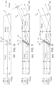
- FIG. 15 A is a sketch of a side view of the light pipe of FIG. 13 C to FIG. 13 I .
- FIG. 15 B is a sketch of a top view of the light pipe of FIG. 15 A .
- the current figures at least in part, define the dimensions of the outcoupling wedge (additional optical structure 1312 ) to avoid loss of light from the single base optical structure 1310 to be output from the new output surface 1308 .
- Y is the minimum length of the out coupling wedge (along an edge from the single base optical structure to the output surface)
- h is the height of the single base optical structure 1310
- Z is the length of the lightpipe from the input to output surface
- a is an angle at which an incoming ray reflects off the side of the lightpipe to intersect where the extension of the wedge meets an other surface of the lightpipe
- H is the height of the out coupled ray (from the edge of the wedge/additional optical structure 1312 to the output surface)
- V is the height of the wedge beyond the light pipe base optical structure 1310
- ⁇ is the angle of the wedge between the output surface and a surface of the base optical structure 1310 .
- a typical ratio to allow sufficient color mixing is “5 ⁇ [Z/h] ⁇ 10”.
- FIG. 16 A is a sketch of a conventional folded light pipe 1600 using a reflective coating 1606 (i.e., mirror coating) to achieve re-direction of the light path of input light 1602 to output light 1603 .
- a reflective coating 1606 i.e., mirror coating
- light can be lost during propagation through the light pipe 1600 via at least two light ray arrangements, for example, input light 1604 couples out as lost output light 1605 and input light 1608 couples out (escapes) as lost output light 1609 .
- FIG. 16 B is a sketch of an improved light pipe 1610 .
- an interface 1620 is configured between the first optical structure P 1 and a fourth optical structure P 4 , and also configured between the fourth optical structure P 4 and the second optical structure P 2 .
- the fourth optical structure P 4 has a mirrored internal surface 1606 configured on a side of the fourth optical structure P 4 other than the sides adjoining the first P 1 and second P 2 optical structures.
- a typical interface 1620 is using a low index optical cement. This low index interface(s) 1620 allows low angles (with respect to normal of the surface) of propagating light rays to pass through the interface 1620 , and high angles of propagating light rays will be reflected by TIR.
- the interface 1620 (each interface, shown as exemplary interface 1620 A and 1620 B) at least in part generates TIR 1616 (shown as respective exemplary TIR 1616 A and 1616 B) and avoids light loss.
- the interface 1620 results in TIR at area 1616 .
- the propagating input light 1604 undergoes TIR 1616 B at the interface 1620 B, the light continues through the second optical structure P 2 , and exits the output surface of the light pipe 1610 as output light 1615 .
- the propagating input light 1608 undergoes TIR 1616 A at the interface 1620 A, the light continues through the second optical structure P 2 , and exits the output surface of the light pipe 1610 as output light 1619 .
- the interface(s) 1620 can be implemented with (an) air gap(s).
- the input surface S 01 and output surface S 23 are tilted in the opposite direction (for example, orthogonal) relative to the tilt of the mirror 1606 .
- the tilt of the input surface S 01 can be described using the eleventh angle ( ⁇ ) and the tilt of the output surface S 23 can be described using the eighth angle ( ⁇ ).
- FIG. 16 C is a sketch of the improved light pipe 1610 of FIG. 16 B , but sketched in three-dimensions (3D) and with alternative tilt and rotation of the input and output surfaces.
- the input surface S 01 and output surface S 23 are tilted in the same direction (for example, parallel) relative to the tilt of the mirror 1606 .
- the input S 01 and output S 23 surfaces can be tilted at any angle relative to the light pipe 600 axis.
- the input S 01 and output S 23 surfaces are tilted between 0° (zero) and 45°, and most preferably tilted at 45°.
- the input surfaces can also lack tilt, that is be straight, as described above for example in reference to FIG. 2 A light pipe 600 A and FIG. 3 light pipe 600 C.
- the input surface S 01 and output surface S 23 are rotated.
- the input surface S 01 is rotated, as shown by arrows 1601 , relative to the (first) longitudinal axis R 1 of the first optical structure P 1 .
- the output surface S 23 is rotated, as shown by arrows 1623 , relative to the second longitudinal axis R 2 of the second optical structure P 2 .
- the input S 01 and output S 23 surfaces can be rotated at any angle relative to the light pipe 600 axis.
- the input S 01 and output S 23 surfaces are rotated to increments of 90° (0°, 90°, 180°, 270°).
- a refractive index of the interface 1620 for example, selecting an optical cement with an appropriate refractive index
- a refractive index of the interface 1620 for example, selecting an optical cement with an appropriate refractive index
Abstract
Description
η0*sin(θ01)=η1*sin(θ10)
η1*sin(θ12)=η2*sin(θ21)
η2*sin(θ23)=η0*sin(θ32)
θ12=θ10−δ
θ23=θ21−(δ−γ)
Claims (19)
Priority Applications (1)
| Application Number | Priority Date | Filing Date | Title |
|---|---|---|---|
| US17/642,748 US11940641B2 (en) | 2019-09-15 | 2020-09-14 | Transversal light pipe |
Applications Claiming Priority (3)
| Application Number | Priority Date | Filing Date | Title |
|---|---|---|---|
| US201962900552P | 2019-09-15 | 2019-09-15 | |
| PCT/IL2020/051005 WO2021048864A1 (en) | 2019-09-15 | 2020-09-14 | Transversal light pipe |
| US17/642,748 US11940641B2 (en) | 2019-09-15 | 2020-09-14 | Transversal light pipe |
Publications (2)
| Publication Number | Publication Date |
|---|---|
| US20220326426A1 US20220326426A1 (en) | 2022-10-13 |
| US11940641B2 true US11940641B2 (en) | 2024-03-26 |
Family
ID=74866278
Family Applications (1)
| Application Number | Title | Priority Date | Filing Date |
|---|---|---|---|
| US17/642,748 Active 2040-12-26 US11940641B2 (en) | 2019-09-15 | 2020-09-14 | Transversal light pipe |
Country Status (8)
| Country | Link |
|---|---|
| US (1) | US11940641B2 (en) |
| EP (1) | EP4031925A4 (en) |
| JP (1) | JP2022546939A (en) |
| KR (1) | KR20220062273A (en) |
| CN (1) | CN114402246A (en) |
| IL (1) | IL291112A (en) |
| TW (1) | TW202115445A (en) |
| WO (1) | WO2021048864A1 (en) |
Families Citing this family (2)
| Publication number | Priority date | Publication date | Assignee | Title |
|---|---|---|---|---|
| EP4088449A4 (en) | 2020-04-20 | 2023-07-05 | Lumus Ltd. | Near-eye display with enhanced laser efficiency and eye safety |
| US20230412915A1 (en) * | 2022-06-15 | 2023-12-21 | Google Llc | Warning light thwart detection for recording devices |
Citations (52)
| Publication number | Priority date | Publication date | Assignee | Title |
|---|---|---|---|---|
| GB2153546A (en) | 1984-02-02 | 1985-08-21 | Pilkington Perkin Elmer Ltd | Optical filtering devices |
| US5096520A (en) | 1990-08-01 | 1992-03-17 | Faris Sades M | Method for producing high efficiency polarizing filters |
| US5398171A (en) * | 1993-09-02 | 1995-03-14 | General Electric Company | Light guide termination arrangement for producing a convergent beam output |
| US5852693A (en) | 1996-11-26 | 1998-12-22 | Ultratech Stepper, Inc. | Low-loss light redirection apparatus |
| US5905837A (en) | 1997-07-22 | 1999-05-18 | Nec Usa, Inc. | Side emitting optical fiber |
| US6394607B1 (en) | 1996-03-12 | 2002-05-28 | Seiko Epson Corporation | Polarized light separation device, method of fabricating the same and projection display apparatus using the polarized light separation device |
| US20020075454A1 (en) | 2000-12-15 | 2002-06-20 | Hsiung Lin Chi | Optical path design of a reflecting liquid crystal projector |
| US20040095860A1 (en) | 2002-11-19 | 2004-05-20 | Tetsuo Ariyoshi | Information reproducing method and information reproducing apparatus of multilayer optical disk |
| US20050017465A1 (en) | 2003-07-24 | 2005-01-27 | Bergstrom Skegs, Inc. | Wear rod for a snowmobile ski |
| US7148936B1 (en) | 2002-03-04 | 2006-12-12 | Hitachi, Ltd. | Color-separation/synthesis optical system with particular cut-off wavelengths and emission-side polarizer and projection type liquid crystal display device using the same |
| US20070000219A1 (en) | 2005-06-30 | 2007-01-04 | Park Chan J | Air purifier |
| US20070159673A1 (en) | 2005-11-21 | 2007-07-12 | Freeman Mark O | Substrate-guided display with improved image quality |
| US20080025667A1 (en) | 2004-08-05 | 2008-01-31 | Yaakov Amitai | Optical Device for Light Coupling |
| US20090323482A1 (en) | 2008-05-09 | 2009-12-31 | Ricoh Company, Ltd. | Aberration correction element |
| US20100027289A1 (en) | 2008-08-01 | 2010-02-04 | Sony Corporation | Illumination optical device and virtual image display |
| US20100033784A1 (en) | 2006-05-19 | 2010-02-11 | See Real Technologies S.A. | Holographic Projection Device for the Reconstruction of Scenes |
| US20120002256A1 (en) | 2009-02-16 | 2012-01-05 | Lilian Lacoste | Laser Based Image Display System |
| US20120068609A1 (en) | 2009-05-28 | 2012-03-22 | Citizen Holdings Co., Ltd. | Light source device |
| US20130021581A1 (en) | 2010-07-30 | 2013-01-24 | Sony Corporation | Light source unit, illuminator, and display |
| US20130335708A1 (en) | 2010-12-29 | 2013-12-19 | 3M Innovative Properties Company | Refractive polarization converter and polarized color combiner |
| US20150013105A1 (en) | 2013-07-05 | 2015-01-15 | Juin-Ping KUAN | Air-wiping device opening and closing in one level plane |
| JP2015099323A (en) | 2013-11-20 | 2015-05-28 | セイコーエプソン株式会社 | Projector |
| US20150288937A1 (en) | 2014-04-03 | 2015-10-08 | Lite-On Technology Corporation | Projection device |
| US20160116744A1 (en) | 2011-03-22 | 2016-04-28 | Seiko Epson Corporation | Image relay optical system and virtual image display device including the same |
| US20160313567A1 (en) | 2013-12-13 | 2016-10-27 | Dai Nippon Printing Co., Ltd. | Optical scanning device, illumination device, projection apparatus and optical device |
| US20160334625A1 (en) | 2014-01-28 | 2016-11-17 | Olympus Corporation | Head-mounted display device and light guide prism |
| US9551880B2 (en) | 2005-11-08 | 2017-01-24 | Lumus Ltd. | Polarizing optical system |
| US20170045664A1 (en) | 2015-08-14 | 2017-02-16 | Radiant Opto-Electronics (Suzhou) Co. Ltd. | Light guide film, backlight module and display device having the same |
| US20170090094A1 (en) | 2015-09-29 | 2017-03-30 | Shiori OHSUGI | Light guide, virtual image optical system, and virtual image display device |
| US20170242249A1 (en) | 2016-02-19 | 2017-08-24 | Richard Andrew Wall | Waveguide Pupil Relay |
| US20170276947A1 (en) | 2016-03-23 | 2017-09-28 | Seiko Epson Corporation | Image display apparatus and optical element |
| US20180120768A1 (en) | 2016-03-03 | 2018-05-03 | Dualitas Ltd. | Display System |
| US20180129166A1 (en) | 2016-11-10 | 2018-05-10 | Samsung Electronics Co., Ltd. | Holographic display apparatus for providing expanded viewing window |
| US20180188532A1 (en) | 2016-03-03 | 2018-07-05 | Dualitas Ltd. | Display System |
| US20180262725A1 (en) | 2017-03-13 | 2018-09-13 | Omnivision Technologies, Inc. | Imaging system having four image sensors |
| US20180335629A1 (en) | 2017-03-21 | 2018-11-22 | Magic Leap, Inc. | Methods, devices, and systems for illuminating spatial light modulators |
| US20180373262A1 (en) | 2017-06-27 | 2018-12-27 | Boe Technology Group Co., Ltd. | In-vehicle display system, traffic equipment and the image display method |
| US20190022731A1 (en) | 2017-07-24 | 2019-01-24 | Toyota Jidosha Kabushiki Kaisha | Method of manufacturing pipe assembly |
| CN109612384A (en) | 2018-11-01 | 2019-04-12 | 南京理工大学 | A kind of inclined aberration rectification building-out method based on the translation of frequency spectrum sub-pix |
| US10330937B2 (en) | 2011-12-06 | 2019-06-25 | Beijing Ned+Ar Display Technology Co., Ltd. | Near-eye display apparatus |
| US20190196199A1 (en) * | 2017-12-25 | 2019-06-27 | Seiko Epson Corporation | Light-guiding device and display device |
| US20200012086A1 (en) * | 2017-01-19 | 2020-01-09 | Olympus Corporation | Optical module and endoscope |
| US20200183079A1 (en) | 2017-05-19 | 2020-06-11 | Seereal Technologies S.A. | Display device comprising a light guide |
| US20200209667A1 (en) | 2017-07-19 | 2020-07-02 | Lumus Ltd. | Lcos illumination via loe |
| US20200278558A1 (en) | 2019-02-28 | 2020-09-03 | Seiko Epson Corporation | Image display device and virtual image display apparatus |
| US20200326655A1 (en) | 2019-04-09 | 2020-10-15 | GM Global Technology Operations LLC | Speckle reduction with image dithering |
| US10859845B2 (en) | 2017-03-31 | 2020-12-08 | Nec Corporation | Projection device, projection image control method, and recording medium having projection image control program recorded thereon |
| US20220197037A1 (en) | 2019-06-26 | 2022-06-23 | Wave Optics Ltd. | Pupil relay system |
| US20220317467A1 (en) | 2019-09-04 | 2022-10-06 | Lumus Ltd. | Optical Devices Having Dichroic Beam Combiners, Optical Devices for Use with Dichroic Beam Combiners, and Methods of Manufacture Therefor |
| US20220342216A1 (en) | 2019-09-16 | 2022-10-27 | Lumus Ltd. | Compact projector for head-mounted displays |
| US20220373807A1 (en) | 2019-10-23 | 2022-11-24 | Lumus Ltd. | Laser-illuminated displays with enhanced uniformity and/or eye safety |
| US20230019309A1 (en) | 2019-12-19 | 2023-01-19 | Lumus Ltd. | Image projector using a phase image generator |
Family Cites Families (1)
| Publication number | Priority date | Publication date | Assignee | Title |
|---|---|---|---|---|
| GB201002085D0 (en) * | 2010-02-09 | 2010-03-24 | Qinetiq Ltd | Light generator |
-
2020
- 2020-09-11 TW TW109131946A patent/TW202115445A/en unknown
- 2020-09-14 WO PCT/IL2020/051005 patent/WO2021048864A1/en unknown
- 2020-09-14 KR KR1020227005693A patent/KR20220062273A/en unknown
- 2020-09-14 EP EP20864250.4A patent/EP4031925A4/en active Pending
- 2020-09-14 CN CN202080064759.XA patent/CN114402246A/en active Pending
- 2020-09-14 JP JP2022510224A patent/JP2022546939A/en active Pending
- 2020-09-14 US US17/642,748 patent/US11940641B2/en active Active
-
2022
- 2022-03-03 IL IL291112A patent/IL291112A/en unknown
Patent Citations (54)
| Publication number | Priority date | Publication date | Assignee | Title |
|---|---|---|---|---|
| GB2153546A (en) | 1984-02-02 | 1985-08-21 | Pilkington Perkin Elmer Ltd | Optical filtering devices |
| US5096520A (en) | 1990-08-01 | 1992-03-17 | Faris Sades M | Method for producing high efficiency polarizing filters |
| US5398171A (en) * | 1993-09-02 | 1995-03-14 | General Electric Company | Light guide termination arrangement for producing a convergent beam output |
| US6394607B1 (en) | 1996-03-12 | 2002-05-28 | Seiko Epson Corporation | Polarized light separation device, method of fabricating the same and projection display apparatus using the polarized light separation device |
| US5852693A (en) | 1996-11-26 | 1998-12-22 | Ultratech Stepper, Inc. | Low-loss light redirection apparatus |
| US5905837A (en) | 1997-07-22 | 1999-05-18 | Nec Usa, Inc. | Side emitting optical fiber |
| US20020075454A1 (en) | 2000-12-15 | 2002-06-20 | Hsiung Lin Chi | Optical path design of a reflecting liquid crystal projector |
| US7148936B1 (en) | 2002-03-04 | 2006-12-12 | Hitachi, Ltd. | Color-separation/synthesis optical system with particular cut-off wavelengths and emission-side polarizer and projection type liquid crystal display device using the same |
| US20040095860A1 (en) | 2002-11-19 | 2004-05-20 | Tetsuo Ariyoshi | Information reproducing method and information reproducing apparatus of multilayer optical disk |
| US20050017465A1 (en) | 2003-07-24 | 2005-01-27 | Bergstrom Skegs, Inc. | Wear rod for a snowmobile ski |
| US20080025667A1 (en) | 2004-08-05 | 2008-01-31 | Yaakov Amitai | Optical Device for Light Coupling |
| US20070000219A1 (en) | 2005-06-30 | 2007-01-04 | Park Chan J | Air purifier |
| US9551880B2 (en) | 2005-11-08 | 2017-01-24 | Lumus Ltd. | Polarizing optical system |
| US20070159673A1 (en) | 2005-11-21 | 2007-07-12 | Freeman Mark O | Substrate-guided display with improved image quality |
| US20100033784A1 (en) | 2006-05-19 | 2010-02-11 | See Real Technologies S.A. | Holographic Projection Device for the Reconstruction of Scenes |
| US20090323482A1 (en) | 2008-05-09 | 2009-12-31 | Ricoh Company, Ltd. | Aberration correction element |
| US20100027289A1 (en) | 2008-08-01 | 2010-02-04 | Sony Corporation | Illumination optical device and virtual image display |
| US20120002256A1 (en) | 2009-02-16 | 2012-01-05 | Lilian Lacoste | Laser Based Image Display System |
| US20120068609A1 (en) | 2009-05-28 | 2012-03-22 | Citizen Holdings Co., Ltd. | Light source device |
| US20130021581A1 (en) | 2010-07-30 | 2013-01-24 | Sony Corporation | Light source unit, illuminator, and display |
| US20130335708A1 (en) | 2010-12-29 | 2013-12-19 | 3M Innovative Properties Company | Refractive polarization converter and polarized color combiner |
| US20160116744A1 (en) | 2011-03-22 | 2016-04-28 | Seiko Epson Corporation | Image relay optical system and virtual image display device including the same |
| US10330937B2 (en) | 2011-12-06 | 2019-06-25 | Beijing Ned+Ar Display Technology Co., Ltd. | Near-eye display apparatus |
| US20150013105A1 (en) | 2013-07-05 | 2015-01-15 | Juin-Ping KUAN | Air-wiping device opening and closing in one level plane |
| JP2015099323A (en) | 2013-11-20 | 2015-05-28 | セイコーエプソン株式会社 | Projector |
| US20160313567A1 (en) | 2013-12-13 | 2016-10-27 | Dai Nippon Printing Co., Ltd. | Optical scanning device, illumination device, projection apparatus and optical device |
| US20160334625A1 (en) | 2014-01-28 | 2016-11-17 | Olympus Corporation | Head-mounted display device and light guide prism |
| US20150288937A1 (en) | 2014-04-03 | 2015-10-08 | Lite-On Technology Corporation | Projection device |
| US20170045664A1 (en) | 2015-08-14 | 2017-02-16 | Radiant Opto-Electronics (Suzhou) Co. Ltd. | Light guide film, backlight module and display device having the same |
| US10007046B2 (en) * | 2015-08-14 | 2018-06-26 | Radiant Opto-Electronics (Suzhou) Co., Ltd. | Light guide film, backlight module and display device having the same |
| US20170090094A1 (en) | 2015-09-29 | 2017-03-30 | Shiori OHSUGI | Light guide, virtual image optical system, and virtual image display device |
| US20170242249A1 (en) | 2016-02-19 | 2017-08-24 | Richard Andrew Wall | Waveguide Pupil Relay |
| US20180120768A1 (en) | 2016-03-03 | 2018-05-03 | Dualitas Ltd. | Display System |
| US20180188532A1 (en) | 2016-03-03 | 2018-07-05 | Dualitas Ltd. | Display System |
| US20170276947A1 (en) | 2016-03-23 | 2017-09-28 | Seiko Epson Corporation | Image display apparatus and optical element |
| US20180129166A1 (en) | 2016-11-10 | 2018-05-10 | Samsung Electronics Co., Ltd. | Holographic display apparatus for providing expanded viewing window |
| US20200012086A1 (en) * | 2017-01-19 | 2020-01-09 | Olympus Corporation | Optical module and endoscope |
| US20180262725A1 (en) | 2017-03-13 | 2018-09-13 | Omnivision Technologies, Inc. | Imaging system having four image sensors |
| US20190018245A1 (en) | 2017-03-21 | 2019-01-17 | Magic Leap, Inc. | Methods, devices, and systems for illuminating spatial light modulators |
| US20180335629A1 (en) | 2017-03-21 | 2018-11-22 | Magic Leap, Inc. | Methods, devices, and systems for illuminating spatial light modulators |
| US10859845B2 (en) | 2017-03-31 | 2020-12-08 | Nec Corporation | Projection device, projection image control method, and recording medium having projection image control program recorded thereon |
| US20200183079A1 (en) | 2017-05-19 | 2020-06-11 | Seereal Technologies S.A. | Display device comprising a light guide |
| US20180373262A1 (en) | 2017-06-27 | 2018-12-27 | Boe Technology Group Co., Ltd. | In-vehicle display system, traffic equipment and the image display method |
| US20200209667A1 (en) | 2017-07-19 | 2020-07-02 | Lumus Ltd. | Lcos illumination via loe |
| US20190022731A1 (en) | 2017-07-24 | 2019-01-24 | Toyota Jidosha Kabushiki Kaisha | Method of manufacturing pipe assembly |
| US20190196199A1 (en) * | 2017-12-25 | 2019-06-27 | Seiko Epson Corporation | Light-guiding device and display device |
| CN109612384A (en) | 2018-11-01 | 2019-04-12 | 南京理工大学 | A kind of inclined aberration rectification building-out method based on the translation of frequency spectrum sub-pix |
| US20200278558A1 (en) | 2019-02-28 | 2020-09-03 | Seiko Epson Corporation | Image display device and virtual image display apparatus |
| US20200326655A1 (en) | 2019-04-09 | 2020-10-15 | GM Global Technology Operations LLC | Speckle reduction with image dithering |
| US20220197037A1 (en) | 2019-06-26 | 2022-06-23 | Wave Optics Ltd. | Pupil relay system |
| US20220317467A1 (en) | 2019-09-04 | 2022-10-06 | Lumus Ltd. | Optical Devices Having Dichroic Beam Combiners, Optical Devices for Use with Dichroic Beam Combiners, and Methods of Manufacture Therefor |
| US20220342216A1 (en) | 2019-09-16 | 2022-10-27 | Lumus Ltd. | Compact projector for head-mounted displays |
| US20220373807A1 (en) | 2019-10-23 | 2022-11-24 | Lumus Ltd. | Laser-illuminated displays with enhanced uniformity and/or eye safety |
| US20230019309A1 (en) | 2019-12-19 | 2023-01-19 | Lumus Ltd. | Image projector using a phase image generator |
Non-Patent Citations (2)
| Title |
|---|
| Lynch et al. "Beam Manipulation: Prisms vs. Mirrors",Photonik International pp. 45-47. Mar. 2009. Available since Sep. 20, 2016 at the following URL: <http://www.edmundoptics.com/globalassets/resources/articles/beammanipulation-prisms-vs-mirrors-en.pdf> Lynch et al. Mar. 31, 2009 (Mar. 31, 2009). |
| M. Kivanc Hedili et al "Light-efficient augmented reality display with steerable eyebox", Optics Express vol. 27, Issue 9, pp. 12572-12581 (2019) ⋅https://doi.org/10.1364/OE.27.012572. |
Also Published As
| Publication number | Publication date |
|---|---|
| EP4031925A4 (en) | 2022-11-23 |
| TW202115445A (en) | 2021-04-16 |
| IL291112A (en) | 2022-05-01 |
| JP2022546939A (en) | 2022-11-10 |
| KR20220062273A (en) | 2022-05-16 |
| WO2021048864A1 (en) | 2021-03-18 |
| CN114402246A (en) | 2022-04-26 |
| EP4031925A1 (en) | 2022-07-27 |
| US20220326426A1 (en) | 2022-10-13 |
| WO2021048864A9 (en) | 2022-08-11 |
Similar Documents
| Publication | Publication Date | Title |
|---|---|---|
| JP7249294B2 (en) | Light-directing optical element with multiaxial internal air gap extension | |
| JP7417234B2 (en) | Optical system including a light guiding optical element with a partially reflective internal surface | |
| KR102537642B1 (en) | LCOS lighting via LOE | |
| CN208780908U (en) | Illumination optical apparatus | |
| US20210072534A1 (en) | Exit pupil expander | |
| JPWO2019142177A5 (en) | ||
| US11940641B2 (en) | Transversal light pipe | |
| JP2009503793A (en) | Etendue-conserving illumination optics for backlights and frontlights | |
| US11815709B2 (en) | Optical devices for mitigating ghost images | |
| US11902716B2 (en) | Optical systems with compact image projector | |
| TWM571489U (en) | Optical lighting device |
Legal Events
| Date | Code | Title | Description |
|---|---|---|---|
| AS | Assignment |
Owner name: LUMUS LTD., ISRAEL Free format text: ASSIGNMENT OF ASSIGNORS INTEREST;ASSIGNORS:EISENFELD, TSION;GELBERG, JONATHAN;REEL/FRAME:059252/0877 Effective date: 20200903 |
|
| FEPP | Fee payment procedure |
Free format text: ENTITY STATUS SET TO UNDISCOUNTED (ORIGINAL EVENT CODE: BIG.); ENTITY STATUS OF PATENT OWNER: LARGE ENTITY |
|
| STPP | Information on status: patent application and granting procedure in general |
Free format text: DOCKETED NEW CASE - READY FOR EXAMINATION |
|
| STPP | Information on status: patent application and granting procedure in general |
Free format text: NON FINAL ACTION MAILED |
|
| STPP | Information on status: patent application and granting procedure in general |
Free format text: FINAL REJECTION MAILED |
|
| STPP | Information on status: patent application and granting procedure in general |
Free format text: RESPONSE AFTER FINAL ACTION FORWARDED TO EXAMINER |
|
| STPP | Information on status: patent application and granting procedure in general |
Free format text: ADVISORY ACTION MAILED |
|
| STPP | Information on status: patent application and granting procedure in general |
Free format text: RESPONSE AFTER FINAL ACTION FORWARDED TO EXAMINER |
|
| STPP | Information on status: patent application and granting procedure in general |
Free format text: NOTICE OF ALLOWANCE MAILED -- APPLICATION RECEIVED IN OFFICE OF PUBLICATIONS |
|
| STPP | Information on status: patent application and granting procedure in general |
Free format text: PUBLICATIONS -- ISSUE FEE PAYMENT RECEIVED |
|
| STPP | Information on status: patent application and granting procedure in general |
Free format text: PUBLICATIONS -- ISSUE FEE PAYMENT VERIFIED |
|
| STCF | Information on status: patent grant |
Free format text: PATENTED CASE |