US11938581B2 - Power device - Google Patents
Power device Download PDFInfo
- Publication number
- US11938581B2 US11938581B2 US17/526,099 US202117526099A US11938581B2 US 11938581 B2 US11938581 B2 US 11938581B2 US 202117526099 A US202117526099 A US 202117526099A US 11938581 B2 US11938581 B2 US 11938581B2
- Authority
- US
- United States
- Prior art keywords
- mounting plate
- piece
- mounting table
- positioning
- screw rod
- Prior art date
- Legal status (The legal status is an assumption and is not a legal conclusion. Google has not performed a legal analysis and makes no representation as to the accuracy of the status listed.)
- Active, expires
Links
- 238000003825 pressing Methods 0.000 claims description 30
- 238000009434 installation Methods 0.000 claims description 29
- 238000000034 method Methods 0.000 claims description 13
- 239000002023 wood Substances 0.000 description 5
- 238000003780 insertion Methods 0.000 description 4
- 230000037431 insertion Effects 0.000 description 4
- 238000003754 machining Methods 0.000 description 3
- 230000008569 process Effects 0.000 description 3
- 238000005520 cutting process Methods 0.000 description 2
- 238000009966 trimming Methods 0.000 description 2
- 230000001154 acute effect Effects 0.000 description 1
- 230000004075 alteration Effects 0.000 description 1
- 230000008901 benefit Effects 0.000 description 1
- 210000000078 claw Anatomy 0.000 description 1
- 238000012986 modification Methods 0.000 description 1
- 230000004048 modification Effects 0.000 description 1
- 238000003860 storage Methods 0.000 description 1
- 238000006467 substitution reaction Methods 0.000 description 1
Images


Classifications
-
- B—PERFORMING OPERATIONS; TRANSPORTING
- B23—MACHINE TOOLS; METAL-WORKING NOT OTHERWISE PROVIDED FOR
- B23Q—DETAILS, COMPONENTS, OR ACCESSORIES FOR MACHINE TOOLS, e.g. ARRANGEMENTS FOR COPYING OR CONTROLLING; MACHINE TOOLS IN GENERAL CHARACTERISED BY THE CONSTRUCTION OF PARTICULAR DETAILS OR COMPONENTS; COMBINATIONS OR ASSOCIATIONS OF METAL-WORKING MACHINES, NOT DIRECTED TO A PARTICULAR RESULT
- B23Q3/00—Devices holding, supporting, or positioning work or tools, of a kind normally removable from the machine
- B23Q3/02—Devices holding, supporting, or positioning work or tools, of a kind normally removable from the machine for mounting on a work-table, tool-slide, or analogous part
-
- B—PERFORMING OPERATIONS; TRANSPORTING
- B27—WORKING OR PRESERVING WOOD OR SIMILAR MATERIAL; NAILING OR STAPLING MACHINES IN GENERAL
- B27C—PLANING, DRILLING, MILLING, TURNING OR UNIVERSAL MACHINES FOR WOOD OR SIMILAR MATERIAL
- B27C5/00—Machines designed for producing special profiles or shaped work, e.g. by rotary cutters; Equipment therefor
- B27C5/02—Machines with table
- B27C5/04—Guide fences for work
-
- B—PERFORMING OPERATIONS; TRANSPORTING
- B27—WORKING OR PRESERVING WOOD OR SIMILAR MATERIAL; NAILING OR STAPLING MACHINES IN GENERAL
- B27F—DOVETAILED WORK; TENONS; SLOTTING MACHINES FOR WOOD OR SIMILAR MATERIAL; NAILING OR STAPLING MACHINES
- B27F5/00—Slotted or mortised work
- B27F5/02—Slotting or mortising machines tools therefor
-
- F—MECHANICAL ENGINEERING; LIGHTING; HEATING; WEAPONS; BLASTING
- F16—ENGINEERING ELEMENTS AND UNITS; GENERAL MEASURES FOR PRODUCING AND MAINTAINING EFFECTIVE FUNCTIONING OF MACHINES OR INSTALLATIONS; THERMAL INSULATION IN GENERAL
- F16B—DEVICES FOR FASTENING OR SECURING CONSTRUCTIONAL ELEMENTS OR MACHINE PARTS TOGETHER, e.g. NAILS, BOLTS, CIRCLIPS, CLAMPS, CLIPS OR WEDGES; JOINTS OR JOINTING
- F16B5/00—Joining sheets or plates, e.g. panels, to one another or to strips or bars parallel to them
- F16B5/0004—Joining sheets, plates or panels in abutting relationship
-
- F—MECHANICAL ENGINEERING; LIGHTING; HEATING; WEAPONS; BLASTING
- F16—ENGINEERING ELEMENTS AND UNITS; GENERAL MEASURES FOR PRODUCING AND MAINTAINING EFFECTIVE FUNCTIONING OF MACHINES OR INSTALLATIONS; THERMAL INSULATION IN GENERAL
- F16B—DEVICES FOR FASTENING OR SECURING CONSTRUCTIONAL ELEMENTS OR MACHINE PARTS TOGETHER, e.g. NAILS, BOLTS, CIRCLIPS, CLAMPS, CLIPS OR WEDGES; JOINTS OR JOINTING
- F16B5/00—Joining sheets or plates, e.g. panels, to one another or to strips or bars parallel to them
- F16B5/02—Joining sheets or plates, e.g. panels, to one another or to strips or bars parallel to them by means of fastening members using screw-thread
- F16B5/0258—Joining sheets or plates, e.g. panels, to one another or to strips or bars parallel to them by means of fastening members using screw-thread using resiliently deformable sleeves, grommets or inserts
-
- F—MECHANICAL ENGINEERING; LIGHTING; HEATING; WEAPONS; BLASTING
- F16—ENGINEERING ELEMENTS AND UNITS; GENERAL MEASURES FOR PRODUCING AND MAINTAINING EFFECTIVE FUNCTIONING OF MACHINES OR INSTALLATIONS; THERMAL INSULATION IN GENERAL
- F16B—DEVICES FOR FASTENING OR SECURING CONSTRUCTIONAL ELEMENTS OR MACHINE PARTS TOGETHER, e.g. NAILS, BOLTS, CIRCLIPS, CLAMPS, CLIPS OR WEDGES; JOINTS OR JOINTING
- F16B5/00—Joining sheets or plates, e.g. panels, to one another or to strips or bars parallel to them
- F16B5/02—Joining sheets or plates, e.g. panels, to one another or to strips or bars parallel to them by means of fastening members using screw-thread
- F16B5/0266—Joining sheets or plates, e.g. panels, to one another or to strips or bars parallel to them by means of fastening members using screw-thread using springs
Definitions
- a router is a power tool for finishing woods, such as cutting, grooving, and trimming woods.
- the router needs to be installed on a router table when in use, and a wood moves stably on the router table so that the router can finish the wood.
- a power device includes a power tool, a mounting plate, and a mounting table.
- the mounting plate is detachably connected to the power tool.
- the mounting table is for installation of the mounting plate.
- the power device further includes a positioning assembly and a locking assembly.
- the positioning assembly includes a positioning piece, where a positioning space is formed between the positioning piece and the mounting table, and an end of the mounting plate is enabled to be inserted into the positioning space so that the mounting plate is pre-positioned.
- the locking assembly includes a movable piece and a locking piece, where the movable piece includes a support position where the mounting plate is supported and an unlocked position where support for the mounting plate is released, and the locking piece fixes at least the mounting plate to the mounting table.
- the movable piece is provided with a guide groove
- the mounting table is provided with a guide rod
- the guide rod passes through the guide groove
- the movable piece is movable with respect to the mounting table through the guide groove.
- the locking piece includes bolts, where the bolts fixedly connect the mounting plate to the mounting table.
- the locking piece includes a first screw rod and a first nut screwed to the first screw rod, the first screw rod is fixedly connected to the mounting table, and the first nut is enabled to be screwed to the first screw rod, so as to lock the movable piece and the mounting table.
- the power device further includes an auxiliary locking assembly, where the auxiliary locking assembly includes a pressing piece and an auxiliary locking piece, the pressing piece is capable of abutting against a side of the mounting plate facing away from the mounting table, and the auxiliary locking piece is capable of locking the pressing piece and the mounting table.
- the auxiliary locking assembly includes a pressing piece and an auxiliary locking piece, the pressing piece is capable of abutting against a side of the mounting plate facing away from the mounting table, and the auxiliary locking piece is capable of locking the pressing piece and the mounting table.
- the auxiliary locking piece includes a second screw rod and a second nut screwed to the second screw rod, the second screw rod is fixedly connected to the mounting table, and the second nut is enabled to be screwed to the second screw rod, so as to abut against the pressing piece.
- the pressing piece and the positioning piece are disposed on the same side of the mounting plate.
- a foolproof assembly is disposed between the mounting table and the mounting plate, the foolproof assembly includes a protrusion and a groove, one of the protrusion or the groove is disposed on the mounting table, the other of the protrusion or the groove is disposed on the mounting plate, and the protrusion is inserted into the groove while the end of the mounting plate is inserted into the positioning space.
- the mounting plate is provided with a plurality of sets of positioning holes, each of the plurality of sets of positioning holes are arranged in a circle, and the plurality of sets of positioning holes are distributed on circles of different diameters.
- the power device further includes a depth adjustment assembly configured to adjust an operation depth of the power tool, where the mounting plate is provided with an escape hole that allows the depth adjustment assembly to pass through.
- the end of the mounting plate is inserted into the positioning space so that the mounting plate is pre-positioned, the movable piece is moved to the support position, and the mounting plate and the mounting table are locked through the locking piece. Therefore, the mounting plate is pre-supported by the movable piece so that a user does not need to hold and support the mounting plate by hand, thereby improving convenience of installation.
- the mounting plate and the power tool will not fall so that the user moves the movable piece to the unlocked position and then pulls the mounting plate out of the positioning space.
- the power device is installed by simple operations and with high efficiency and can be used immediately after installation. Since the positioning space pre-positions the mounting plate and the movable piece pre-supports the mounting plate, after assembly is completed, it can be ensured that a router is flush with a desktop of a router table without the need to adjust flatness, thereby ensuring the machining precision.
- FIG. 1 is a structure view of a power device according to an example of the present disclosure
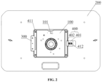
- FIG. 2 is a view illustrating the assembly of a mounting plate and a mounting table of a power device according to an example of the present disclosure
- FIG. 3 is a top view of a power device according to an example of the present disclosure.
- FIG. 4 is a sectional view taken along A-A of FIG. 3 ;
- FIG. 5 is a sectional view taken along B-B of FIG. 3 ;
- FIG. 6 is a view illustrating the assembly of a support grid structure and a mounting table of a power device according to an example of the present disclosure
- FIG. 7 is a view illustrating the assembly of a support leg and a mounting table of a power device according to an example of the present disclosure
- FIG. 8 is a structure view of a support leg according to an example of the present disclosure.
- FIG. 9 is a view illustrating the assembly of a mounting plate and a mounting table of a power device according to another example of the present disclosure.
- FIG. 10 is an exploded view of a mounting plate and a mounting table of a power device according to another example of the present disclosure.
- orientations or position relations indicated by terms such as “center”, “upper”, “lower”, “left”, “right”, “vertical”, “horizontal”, “in”, and “out” are based on the drawings. These orientations or position relations are intended only to facilitate and simplify the description of the present disclosure and not to indicate or imply that a device or element referred to must have such particular orientations or must be configured or operated in such particular orientations. Thus, these orientations or position relations are not to be construed as limiting the present disclosure.
- terms such as “first” and “second” are used only for the purpose of description and are not to be construed as indicating or implying relative importance. Terms “first position” and “second position” are two different positions.
- this example provides a power device.
- the power device includes a power tool and a mounting table 200 .
- the power tool is installed to the mounting table 200 to complete a specific operation. Based on different power tools, the power device can perform different operations to achieve different tasks.
- the power tool is a router and the mounting table 200 is a router table is used.
- the router is a power tool capable of finishing woods, such as cutting, grooving, and trimming woods.
- the power device further includes a mounting plate 100 configured to detachably connect the router to the router table.
- the router is detachably connected to the mounting plate 100 .
- the mounting plate 100 is provided with multiple positioning holes 101
- the router is provided with multiple connection holes
- the multiple positioning holes 101 and the multiple connection holes are arranged in a ring or rectangle according to requirements, and each of multiple screws passes through a respective one of the multiple positioning holes 101 and a respective one of the multiple connection holes so that the router is detachably connected to the mounting plate 100 .
- the mounting plate 100 is provided with multiple sets of positioning holes 101 , each set of positioning holes 101 are arranged in a circle, and the multiple sets of positioning holes 101 are distributed on circles of different diameters so that when the routers of different specifications are installed, different sets of positioning holes 101 can be selected for use according to positions of the connection holes on the router.
- the mounting plate 100 is connected to the router table.
- the power device further includes a positioning assembly and a locking assembly.
- the positioning assembly includes a positioning piece 300 .
- a positioning space is formed between the positioning piece 300 and the mounting table 200 .
- An end of the mounting plate 100 can be inserted into the positioning space so that the mounting plate 100 is pre-positioned.
- the locking assembly includes a movable piece 400 and a locking piece.
- the movable piece 400 includes a support position where the mounting plate 100 is supported and an unlocked position where support for the mounting plate 100 is released. The locking piece fixes at least the mounting plate 100 to the mounting table 200 .
- the end of the mounting plate 100 is inserted into the positioning space so that the mounting plate 100 is pre-positioned, the movable piece 400 is moved to the support position, and the mounting plate 100 and the mounting table 200 are locked through the locking piece. Therefore, the mounting plate 100 is pre-supported by the movable piece 400 so that a user does not need to hold and support the mounting plate 100 by hand, thereby improving convenience of installation.
- the mounting plate 100 and the power tool will not fall so that the user moves the movable piece 400 to the unlocked position and then withdraws the mounting plate 100 from the positioning space.
- the power device is installed by simple operations and with high efficiency and can be used immediately after installation. Since the positioning space pre-positions the mounting plate 100 and the movable piece 400 pre-supports the mounting plate 100 , after assembly is completed, it can be ensured that the router is flush with a desktop of the router table without the need to adjust flatness, thereby ensuring machining precision.
- an installation groove is disposed on a bottom surface of the mounting table 200 , and the mounting plate 100 can be placed in the installation groove.
- the positioning space is enclosed between the positioning piece 300 and the installation groove.
- the mounting plate 100 is a rectangular plate
- the installation groove is correspondingly configured to be a rectangular groove
- a dimension of the rectangular groove is slightly greater than a dimension of the rectangular plate, so as to reduce the difficulty of installing the mounting plate 100 into the installation groove.
- the positioning piece 300 may be plate-shaped, block-shaped, or in other shapes, and the positioning piece 300 and the mounting table 200 may be locked through screws.
- a foolproof assembly is disposed between the mounting table 200 and the mounting plate 100 , the foolproof assembly includes a protrusion and a groove, one of the protrusion or the groove is disposed on the mounting table 200 , the other of the protrusion or the groove is disposed on the mounting plate 100 , and the protrusion is inserted into the groove while the end of the mounting plate 100 is inserted into the positioning space.
- the cooperation between the protrusion and the groove can limit the end of the mounting plate 100 .
- the locking piece includes bolts 411 , installation holes are disposed on a periphery of the mounting plate 100 , such as four corners of the mounting plate 100 , and the bolts 411 are threadedly connected to the mounting table 200 through the installation holes.
- the mounting plate 100 and the mounting table 200 are locked through the bolts 411 .
- the positioning piece 300 and the movable piece 400 are respectively disposed at two ends of the mounting plate 100 . It can be seen that one end of the mounting plate 100 is pre-positioned by the positioning space and the other end of the mounting plate 100 abuts against the movable piece 400 to be supported, thereby improving efficiency of installation and disassembly.
- the movable piece 400 is provided with a guide groove
- the mounting table is provided with a guide rod 412
- the guide rod 412 passes through the guide groove
- the movable piece 400 can move with respect to the mounting table 200 through the guide groove so as to adjust its position.
- the movable piece 400 may move inward to block an end portion of the mounting plate 100 .
- the movable piece 400 and the positioning piece 300 together pre-support the mounting plate 100 so that the mounting plate 100 is prevented from falling down and the user does not need to hold the mounting plate 100 by hand when installing the bolts 411 to fix the mounting plate 100 .
- the movable piece 400 is plate-shaped and includes a connection portion 401 and a pulling portion 402 connected at an angle.
- the connection portion 401 and the pulling portion 402 are both rectangular and plate-shaped structures, and the angle between the connection portion 401 and the pulling portion 402 may be an acute angle, a right angle, or an obtuse angle according to requirements.
- the guide groove is disposed on the connection portion 401 , and the connection portion 401 is slidably connected to the guide rod 412 . The user may pull and displace the movable piece 400 by applying a force to the pulling portion 402 .
- the power device further includes a support grid structure 610 , where the support grid structure 610 is disposed on the desktop of the router table, that is, on a top surface of the mounting table 200 .
- the support grid structure 610 is mainly configured to provide guidance for movement of a wood and provide positioning when the router machines the wood.
- a guide rail 620 and a sliding base 630 slidably connected to the guide rail 620 are disposed on the desktop of the router table, and the sliding base 630 and the support grid structure 610 are locked through connection pieces.
- the sliding base 630 may move along the guide rail 620 , so as to adjust the position of the support grid structure 610 on the router table.
- a scale line is also disposed in a direction parallel to the guide rail 620 on the router table. The scale line may be used for precisely controlling a movement distance of the support grid structure 610 on the router table.
- an installation hole is disposed on the support grid structure 610 , a first stud 641 is fixedly disposed on the sliding base 630 , a connection end of the first stud 641 is welded, bonded, or integrally formed on the sliding base 630 , and the first stud 641 passes through a corresponding installation hole and is threadedly connected to a first knob 642 .
- the support grid structure 610 and the sliding base 630 can be locked by screwing the first knob 642 .
- two installation holes are arranged at intervals along a length direction of the support grid structure 610 .
- two guide rails 620 and two sliding bases 630 are respectively disposed in a one-to-one correspondence with the two installation holes.
- a guide rail groove is disposed on the router table, and the guide rail 620 is placed in the guide rail groove.
- a free end of the guide rail 620 is folded inward to form an inverted T-shaped groove in the guide rail 620
- the sliding base 630 is configured to be an inverted T-shaped structure fitting with the inverted T-shaped groove so that the guide rail 620 stably limits the sliding base 630 .
- the guide rail 620 , the sliding base 630 , the first stud 641 , and the first knob 642 are provided as one group and one group, two groups, or more than two groups may be provided according to requirements.
- one, two, or more than two installation holes are disposed on the support grid structure 610 .
- the power device further includes a support leg 710 , where the support leg 710 is connected to a bottom surface of the router table to stably support the router table.
- Two, three, four, or more support legs 710 may be provided according to requirements.
- the router table has two support legs 710 , which are a left support leg and a right support leg, respectively.
- a slot 711 is disposed at a top of the support leg 710 .
- the slot 711 is a slot with a U-shaped opening.
- a second stud 720 protrudes out of the bottom surface of the router table, one end of the second stud 720 is fixed to the router table, the other end of the second stud 720 may pass through a bottom or a side portion of the slot 711 , and a second knob 730 is threadedly connected to the second stud 720 .
- the support leg 710 and the router table can be locked by screwing the second knob 730 .
- the slot 711 may be configured to be a narrowing structure with a relatively narrow opening and a relatively wide inside, and a diameter of the second stud 720 is made greater than a width of the opening of the slot 711 and less than a width of the inside of the slot 711 .
- the second knob 730 is a claw knob to facilitate screwing.
- the power device further includes a front plate 800 , where the front plate 800 is detachably connected between the left support leg and the right support leg.
- the front plate 800 is detachably connected between the left support leg and the right support leg.
- one insertion block is disposed on each of the left support leg and the right support leg, one insertion groove is disposed at each of two ends of the front plate 800 , and the insertion block may be inserted into the insertion groove so that the front plate 800 and the support leg 710 can be quickly assembled.
- the support leg 710 may also be used as a storage box, where the support leg 710 further includes an openable cover 712 , and a space for storing a tool is formed inside the support leg 710 .
- the power device in the example of the present disclosure further includes a depth adjustment assembly configured to adjust an operation depth of an operation head of the router. Therefore, the mounting plate 100 is further provided with an escape hole that allows the depth adjustment assembly to pass through.
- the depth adjustment assembly may be a depth adjustment assembly that comes with the router or may be another independently configured depth adjustment assembly.
- FIGS. 9 and 10 illustrate another example in which the same or corresponding parts use corresponding reference numerals as those in the previous example. For brevity, only the difference between the two examples is described below: the mounting plate 100 is fixedly connected to the mounting table 200 indirectly.
- the locking piece includes a first screw rod 421 and a first nut 422 screwed to the first screw rod 421 , the first screw rod 421 is fixedly connected to the mounting table 200 , and the first nut 422 can be screwed to the first screw rod 421 , so as to lock the movable piece 400 and the mounting table 200 . Since the movable piece 400 supports the mounting plate 100 , the mounting plate 100 and the mounting table 200 can be locked.
- the end of the mounting plate 100 is inserted into the positioning space so that the mounting plate 100 is pre-positioned, the movable piece 400 is moved to the support position, and the first nut 422 is screwed so that the mounting plate 100 and the mounting table 200 can be locked.
- the first nut 422 is unscrewed so that the movable piece 400 and the mounting table 200 can be unlocked, the movable piece 400 is moved to the unlocked position, and the mounting plate 100 is withdrawn from the positioning space.
- the screw rod fits with the nut and the nut is simply screwed so that the power device is installed by a simpler process and with high efficiency and can be used immediately after installation.
- first screw rods 421 may be provided.
- the first nut 422 is provided with a holding portion, so as to improve screwing efficiency.
- the first nut 422 occupies a relatively large space.
- the locking assembly further includes the guide rod 412 , the movable piece 400 is provided with the guide groove, and both the first screw rod 421 and the guide rod 412 pass through the guide groove.
- the first screw rod 421 and the guide rod 412 fit with the guide groove to limit the movable piece 400 and prevent the movable piece 400 from rotating so that the movable piece 400 can only move along a straight line between the support position and the unlocked position.
- an elastic body passes through the first screw rod 421 , and the first nut 422 abuts against the elastic body.
- the elastic body is deformed; and when the first nut 422 is unscrewed, the elastic body is restored.
- the elastic body is provided so that the movable piece 400 can be quickly detached from the mounting table 200 when the mounting plate 100 is disassembled, thereby achieving quick disassembly.
- the elastic body is a spiral spring.
- the power device further includes an auxiliary locking assembly.
- the auxiliary locking assembly includes a pressing piece 500 and an auxiliary locking piece.
- the pressing piece 500 can abut against a side of the mounting plate 100 facing away from the mounting table 200 , and the auxiliary locking piece can lock the pressing piece 500 and the mounting table 200 .
- the pressing piece 500 in this example is a pressing plate.
- the end of the mounting plate 100 is inserted into the positioning space so that the mounting plate 100 is pre-positioned, the movable piece 400 is moved to the support position, and the locking piece fixes the movable piece 400 to the mounting table 200 to lock the mounting plate 100 and the mounting table 200 .
- the pressing piece 500 abuts against the side of the mounting plate 100 facing away from the mounting table 200 , and the auxiliary locking piece locks the pressing piece 500 and the mounting table 200 .
- the auxiliary locking assembly cooperates with the locking assembly so that the mounting plate 100 is double-fixed and thus the mounting plate 100 is installed more stably.
- the auxiliary locking piece includes a second screw rod 511 and a second nut 512 screwed to the second screw rod 511 , the second screw rod 511 is fixedly connected to the mounting table 200 , and the second nut 512 can be screwed to the second screw rod 511 , so as to abut against the pressing piece 500 .
- the pressing piece 500 abuts against the side of the mounting plate 100 facing away from the mounting table 200 , and the second nut 512 is screwed so that the pressing piece 500 and the mounting table 200 can be locked.
- the screw rod fits with the nut and the nut is simply screwed so that the power device is installed by a simpler process and with high efficiency and can be used immediately after installation.
- the pressing piece 500 and the positioning piece 300 are disposed on the same side of the mounting plate 100 .
- the pressing piece 500 is disposed on an outer side of the positioning piece 300 and configured to press both the positioning piece 300 and the mounting plate 100 to fix the mounting plate 100 .
- auxiliary locking assembly may also be staggered from positions of the positioning assembly and the locking assembly to fix another position of the mounting plate 100 .
- an escape groove is disposed at a middle position of the positioning piece 300 , and the pressing piece 500 is disposed in a positioning groove.
- the second screw rod 511 is disposed without interference with the pre-positioning of the mounting plate 100 by the positioning piece 300 .
- an elastic body passes through the second screw rod 511 , and the pressing piece 500 abuts against the elastic body.
- the elastic body is deformed; and when the second nut 512 is unscrewed, the elastic body is restored.
- the elastic body is provided so that the pressing plate can be quickly detached from the mounting table 200 when the mounting plate 100 is disassembled, thereby achieving quick disassembly.
- the elastic body is a spiral spring.
Abstract
Description
Claims (18)
Applications Claiming Priority (2)
| Application Number | Priority Date | Filing Date | Title |
|---|---|---|---|
| CN202011294600.5 | 2020-11-18 | ||
| CN202011294600.5A CN114516098A (en) | 2020-11-18 | 2020-11-18 | Power equipment |
Publications (2)
| Publication Number | Publication Date |
|---|---|
| US20220152760A1 US20220152760A1 (en) | 2022-05-19 |
| US11938581B2 true US11938581B2 (en) | 2024-03-26 |
Family
ID=81587383
Family Applications (1)
| Application Number | Title | Priority Date | Filing Date |
|---|---|---|---|
| US17/526,099 Active 2042-03-09 US11938581B2 (en) | 2020-11-18 | 2021-11-15 | Power device |
Country Status (2)
| Country | Link |
|---|---|
| US (1) | US11938581B2 (en) |
| CN (1) | CN114516098A (en) |
Citations (13)
| Publication number | Priority date | Publication date | Assignee | Title |
|---|---|---|---|---|
| US5715880A (en) * | 1996-03-07 | 1998-02-10 | Tucker; Edwin C. | Router table top |
| US6382276B1 (en) * | 2001-05-22 | 2002-05-07 | Wolfcraft, Inc. | Router table adapter base plate |
| US20050230003A1 (en) * | 2004-03-05 | 2005-10-20 | Uwe Radermacher | Router table and accessories |
| US7409973B2 (en) * | 2004-08-25 | 2008-08-12 | Lee Valley Tools Ltd. | Router table plate assembly |
| US7785049B2 (en) * | 2006-02-18 | 2010-08-31 | Wolfcraft Gmbh | Fastening device for a hand router on a milling table |
| US20110073335A1 (en) * | 2009-09-29 | 2011-03-31 | Makita Corporation | Power tools |
| US7921888B2 (en) * | 2007-02-07 | 2011-04-12 | Black & Decker Inc. | Router table |
| US7934961B2 (en) * | 2008-06-11 | 2011-05-03 | Tyco Electronics Corporation | Low profile contact |
| US7946318B2 (en) * | 2007-06-12 | 2011-05-24 | Black & Decker Inc. | Variable depth router and base |
| US9346144B2 (en) * | 2012-12-20 | 2016-05-24 | Robert Bosch Gmbh | Hand-held power tool having a support device |
| US9403221B2 (en) * | 2013-03-14 | 2016-08-02 | Robert Bosch Gmbh | One handed plunge base for a router |
| US20210023664A1 (en) * | 2018-03-21 | 2021-01-28 | Plöckl Gmbh & Co. Industrieoptik Kg | Milling adapter for a work table |
| US11173624B2 (en) * | 2017-05-09 | 2021-11-16 | Nomis Llc | Router base having adjustable mounting slots |
-
2020
- 2020-11-18 CN CN202011294600.5A patent/CN114516098A/en active Pending
-
2021
- 2021-11-15 US US17/526,099 patent/US11938581B2/en active Active
Patent Citations (13)
| Publication number | Priority date | Publication date | Assignee | Title |
|---|---|---|---|---|
| US5715880A (en) * | 1996-03-07 | 1998-02-10 | Tucker; Edwin C. | Router table top |
| US6382276B1 (en) * | 2001-05-22 | 2002-05-07 | Wolfcraft, Inc. | Router table adapter base plate |
| US20050230003A1 (en) * | 2004-03-05 | 2005-10-20 | Uwe Radermacher | Router table and accessories |
| US7409973B2 (en) * | 2004-08-25 | 2008-08-12 | Lee Valley Tools Ltd. | Router table plate assembly |
| US7785049B2 (en) * | 2006-02-18 | 2010-08-31 | Wolfcraft Gmbh | Fastening device for a hand router on a milling table |
| US7921888B2 (en) * | 2007-02-07 | 2011-04-12 | Black & Decker Inc. | Router table |
| US7946318B2 (en) * | 2007-06-12 | 2011-05-24 | Black & Decker Inc. | Variable depth router and base |
| US7934961B2 (en) * | 2008-06-11 | 2011-05-03 | Tyco Electronics Corporation | Low profile contact |
| US20110073335A1 (en) * | 2009-09-29 | 2011-03-31 | Makita Corporation | Power tools |
| US9346144B2 (en) * | 2012-12-20 | 2016-05-24 | Robert Bosch Gmbh | Hand-held power tool having a support device |
| US9403221B2 (en) * | 2013-03-14 | 2016-08-02 | Robert Bosch Gmbh | One handed plunge base for a router |
| US11173624B2 (en) * | 2017-05-09 | 2021-11-16 | Nomis Llc | Router base having adjustable mounting slots |
| US20210023664A1 (en) * | 2018-03-21 | 2021-01-28 | Plöckl Gmbh & Co. Industrieoptik Kg | Milling adapter for a work table |
Also Published As
| Publication number | Publication date |
|---|---|
| US20220152760A1 (en) | 2022-05-19 |
| CN114516098A (en) | 2022-05-20 |
Similar Documents
| Publication | Publication Date | Title |
|---|---|---|
| US10058992B2 (en) | Portable work bench | |
| US6644157B2 (en) | Table saw having adjustable worktable | |
| US4630656A (en) | Router attachment | |
| US5507607A (en) | Integrated drawer side tool | |
| EP1592528B1 (en) | Tool attachment system and router attachment and method incorporating same | |
| US20210078156A1 (en) | Supplementary support assembly for a workpiece support assembly | |
| US20120217689A1 (en) | Drawer front jig | |
| US6237457B1 (en) | Apparatus for precisely guiding a workpiece relative to a work surface | |
| CN101774046B (en) | Auxiliary support device | |
| US11938581B2 (en) | Power device | |
| GB2484821A (en) | Universal fence assembly having multi-position stop assemblies for power tool tables | |
| WO1991012939A1 (en) | Woodworking worktable assembly having an extruded t-slot | |
| US6530302B1 (en) | Cabinetmaking system | |
| US9707695B2 (en) | Joint making jig | |
| CN214026131U (en) | Power equipment | |
| KR20190014552A (en) | Foldable worktable for cutting plate | |
| US8632285B2 (en) | Router table clamp system and router table including the clamp system | |
| US8534329B2 (en) | Joint making jig | |
| CN211362118U (en) | A sill frock for construction bolt | |
| US20050268446A1 (en) | Fixture assembly for milling and drilling on woodwork | |
| CN218874336U (en) | Adjustable positioning jig | |
| EP1362658A1 (en) | Machine for sawing panels | |
| CN219725243U (en) | Multi-guide-rod sliding fixing seat | |
| CN220428658U (en) | Drilling machine for sofa processing | |
| CN219617160U (en) | Swing fixing tool |
Legal Events
| Date | Code | Title | Description |
|---|---|---|---|
| AS | Assignment |
Owner name: NANJING CHERVON INDUSTRY CO., LTD., CHINA Free format text: ASSIGNMENT OF ASSIGNORS INTEREST;ASSIGNORS:CHEN, ZHIFENG;ZHU, DIANBO;ZHANG, BO;AND OTHERS;REEL/FRAME:058109/0903 Effective date: 20211111 |
|
| FEPP | Fee payment procedure |
Free format text: ENTITY STATUS SET TO UNDISCOUNTED (ORIGINAL EVENT CODE: BIG.); ENTITY STATUS OF PATENT OWNER: LARGE ENTITY |
|
| STPP | Information on status: patent application and granting procedure in general |
Free format text: DOCKETED NEW CASE - READY FOR EXAMINATION |
|
| STPP | Information on status: patent application and granting procedure in general |
Free format text: NON FINAL ACTION MAILED |
|
| STPP | Information on status: patent application and granting procedure in general |
Free format text: RESPONSE TO NON-FINAL OFFICE ACTION ENTERED AND FORWARDED TO EXAMINER |
|
| STPP | Information on status: patent application and granting procedure in general |
Free format text: FINAL REJECTION MAILED |
|
| STPP | Information on status: patent application and granting procedure in general |
Free format text: RESPONSE AFTER FINAL ACTION FORWARDED TO EXAMINER |
|
| STPP | Information on status: patent application and granting procedure in general |
Free format text: NOTICE OF ALLOWANCE MAILED -- APPLICATION RECEIVED IN OFFICE OF PUBLICATIONS |
|
| STPP | Information on status: patent application and granting procedure in general |
Free format text: PUBLICATIONS -- ISSUE FEE PAYMENT VERIFIED |
|
| STCF | Information on status: patent grant |
Free format text: PATENTED CASE |