US11936800B1 - Case system for portable electronic device - Google Patents
Case system for portable electronic device Download PDFInfo
- Publication number
- US11936800B1 US11936800B1 US18/503,164 US202318503164A US11936800B1 US 11936800 B1 US11936800 B1 US 11936800B1 US 202318503164 A US202318503164 A US 202318503164A US 11936800 B1 US11936800 B1 US 11936800B1
- Authority
- US
- United States
- Prior art keywords
- base
- assembly
- electrical connector
- card reader
- rear assembly
- Prior art date
- Legal status (The legal status is an assumption and is not a legal conclusion. Google has not performed a legal analysis and makes no representation as to the accuracy of the status listed.)
- Active
Links
- 239000002184 metal Substances 0.000 claims description 13
- 230000000712 assembly Effects 0.000 abstract 1
- 238000000429 assembly Methods 0.000 abstract 1
- 238000010276 construction Methods 0.000 description 2
- 238000003780 insertion Methods 0.000 description 2
- 230000037431 insertion Effects 0.000 description 2
- 238000000034 method Methods 0.000 description 2
- 238000012986 modification Methods 0.000 description 2
- 230000004048 modification Effects 0.000 description 2
- 239000004593 Epoxy Substances 0.000 description 1
- 239000006261 foam material Substances 0.000 description 1
- 238000004519 manufacturing process Methods 0.000 description 1
- 239000000463 material Substances 0.000 description 1
- 239000000203 mixture Substances 0.000 description 1
- 239000003607 modifier Substances 0.000 description 1
- 239000000565 sealant Substances 0.000 description 1
- 230000000153 supplemental effect Effects 0.000 description 1
Images


Classifications
-
- H—ELECTRICITY
- H04—ELECTRIC COMMUNICATION TECHNIQUE
- H04M—TELEPHONIC COMMUNICATION
- H04M1/00—Substation equipment, e.g. for use by subscribers
- H04M1/02—Constructional features of telephone sets
- H04M1/0202—Portable telephone sets, e.g. cordless phones, mobile phones or bar type handsets
- H04M1/026—Details of the structure or mounting of specific components
-
- H—ELECTRICITY
- H04—ELECTRIC COMMUNICATION TECHNIQUE
- H04B—TRANSMISSION
- H04B1/00—Details of transmission systems, not covered by a single one of groups H04B3/00 - H04B13/00; Details of transmission systems not characterised by the medium used for transmission
- H04B1/38—Transceivers, i.e. devices in which transmitter and receiver form a structural unit and in which at least one part is used for functions of transmitting and receiving
- H04B1/3827—Portable transceivers
- H04B1/3888—Arrangements for carrying or protecting transceivers
-
- H—ELECTRICITY
- H04—ELECTRIC COMMUNICATION TECHNIQUE
- H04M—TELEPHONIC COMMUNICATION
- H04M1/00—Substation equipment, e.g. for use by subscribers
- H04M1/02—Constructional features of telephone sets
- H04M1/0202—Portable telephone sets, e.g. cordless phones, mobile phones or bar type handsets
-
- H—ELECTRICITY
- H04—ELECTRIC COMMUNICATION TECHNIQUE
- H04M—TELEPHONIC COMMUNICATION
- H04M2250/00—Details of telephonic subscriber devices
- H04M2250/14—Details of telephonic subscriber devices including a card reading device
Definitions
- a case system for a portable electronic device includes (I) a front assembly including (A) a first side, (B) a second side, (C) a third side, (D) a fourth side, and (E) a base extending perpendicular to and extending between the first side, the second side, the third side, and the fourth side, wherein at least a portion of the first side extends parallel to at least a portion of the second side, wherein at least a portion of the third side extends parallel to at least a portion of the fourth side, and wherein at least the portion of the first side extends perpendicular to the at least a portion of the third side; (II) a rear assembly coupled to the front assembly, the rear assembly including (A) a first side, (B) a second side, (C) a third side, (D) a fourth side, and (E) a base extending perpendicular to and extending between the first side, the second side, the third side, and the fourth side,
- the base of the rear assembly includes a first aperture to receive the first electrical connector assembly, wherein a portion of the first electrical connector assembly protrudes through the first aperture from the interior side of the base to the exterior side of the base thereby providing accessibility to the plurality of electrical contacts of the first electrical connector assembly from the exterior side of the base, wherein the base of the rear assembly includes a second aperture to receive the second electrical connector assembly, and wherein a portion of the second electrical connector assembly protrudes through the second aperture from the interior side of the base to the exterior side of the base thereby providing accessibility to the plurality of electrical contacts of the second electrical connector assembly from the exterior side of the base.
- the exterior side of the base of the rear assembly includes a recess.
- the recess includes a base and a depth
- the exterior side of the base of the rear assembly includes a first portion and a second portion extending in parallel with respect to one another and differing in elevation by a first elevational difference
- the base of the recess is the first portion of the exterior side of the base
- the first elevational difference is the depth of the recess
- the base of the recess includes the first aperture and the second aperture.
- the recess includes a first side, wherein the recess includes a second side, wherein the first side and the second side of the recess extend parallel with respect to one another, wherein the first aperture and the second aperture of the base of the rear assembly are equally spaced from the first side of the recess, and wherein the first aperture and the second aperture of the base of the rear assembly are equally spaced from the second side of the recess.
- the rear assembly includes a metal plate, wherein the metal plate is coupled to the base of the rear assembly, wherein the base of the recess includes a third aperture, and wherein a portion of the metal plate protrudes through the third aperture from the interior side of the base of the rear assembly to the base of the recess thereby providing accessibility to the metal plate from the exterior side of the base of the rear assembly.
- the third aperture of the base of the recess includes a first side and a second side extending parallel with one another, wherein the first plurality of electrical contacts of the first electrical connector assembly includes an electrical contact nearest to the first side of the third aperture, wherein the electrical contact of the first plurality of electrical contacts of the first electrical connector assembly nearest to the first side of the third aperture is spaced from the first side of the recess a first distance, wherein the second plurality of electrical contacts of the second electrical connector assembly includes an electrical contact nearest to the second side of the third aperture, and wherein the electrical contact of the second plurality of electrical contacts of the second electrical connector assembly nearest to the second side of the third aperture is spaced from the second side of the third aperture a second distance equal to the first distance.
- the recess includes at least one first lip protrusion extending from the first side of the recess, and wherein the recess includes at least one second lip protrusion extending from the second side of the recess.
- a card reader including a base and at least one slot, wherein the card reader is couplable with the at least one first lip protrusion and the at least one second lip protrusion of the recess, wherein the at least one slot of the card reader extends in parallel with respect to the base of the card reader, wherein the at least one slot of the card reader is positioned a first elevational distance from base of the card reader, and wherein the depth of the recess of the rear assembly is equal to the first elevational distance.
- an adapter sized and shaped to engage the at least one of lip protrusion extending from the first side of the recess and to engage the at least one of lip protrusion extending from the second side of the recess.
- a card reader wherein the adapter is sized and shaped to couple with the card reader.
- the card reader includes a base and at least one slot, wherein the adapter includes a base positioned a first elevational distance from the at least one slot of the card reader when the adapter is coupled with the card reader, and wherein the depth of the recess of the rear assembly is equal to the first elevational distance.
- the card reader is electrically coupled with the first electrical connector assembly when the card reader is coupled to the rear assembly in a first position, wherein the card reader is electrically coupled with the second electrical connector assembly when the card reader is coupled to the rear assembly in a second position, and wherein the carder reader is rotationally oriented in the second position 180 degrees from the first position.
- a portable electronic device including (I) a front assembly; (II) a rear assembly coupled to the front assembly, the rear assembly including (A) a base including an edge, an interior side facing the front assembly and an exterior side facing away from the front assembly; (III) a first electrical connector assembly coupled with the base of the rear assembly, wherein the first electrical connector assembly includes a first plurality of electrical contacts positioned in a spatial arrangement, and wherein the first plurality of electrical contacts is accessible from the exterior side of the base; and (IV) a second electrical connector assembly coupled with the base of the rear assembly, wherein the second electrical connector assembly includes a second plurality of electrical contacts positioned in a spatial arrangement, wherein the second plurality of electrical contacts is accessible from the exterior side of the base, wherein the spatial arrangement of the second electrical connector assembly is a duplicate of the spatial arrangement of the first electrical connector assembly, and wherein the first electrical connector assembly and the second electrical connector assembly are spaced from the edge of the base a first distance.
- the exterior side of the base of the rear assembly includes a recess
- the rear assembly includes a metal plate coupled to the base of the rear assembly and accessible from the exterior side of the base of the rear assembly, and wherein from the exterior side of the base of the rear assembly the first electrical connector assembly and the second electrical connector assembly are equally spaced from opposite sides of the metal plate.
- a card reader including a base and at least one slot, wherein the card reader is couplable with the recess, wherein the at least one slot of the card reader extends in parallel with respect to the base of the card reader, wherein the at least one slot of the card reader is positioned a first elevational distance from base of the card reader, and wherein the depth of the recess of the rear assembly is equal to the first elevational distance.
- a case including for a portable electronic device including (I) a rear assembly including (A) a base including an edge and an exterior side; (II) a first electrical connector assembly coupled with the base of the rear assembly and accessible from the exterior side of the base; and (III) a second electrical connector assembly coupled with the base of the rear assembly and accessible from the exterior side of the base, and wherein the first electrical connector assembly and the second electrical connector assembly are spaced from the edge of the base a first distance.
- the adapter is sized and shaped to couple with the card reader
- the exterior side of the base of the rear assembly includes a recess
- the adapter is sized and shaped to couple with the recess having a depth
- the card reader includes a base and at least one slot
- the adapter includes a base positioned a first elevational distance from the at least one slot of the card reader when the adapter is coupled with the card reader, and wherein the depth of the recess of the rear assembly is equal to the first elevational distance.
- the card reader is electrically coupled with the first electrical connector assembly when the card reader is coupled to the rear assembly in a first position, wherein the card reader is electrically coupled with the second electrical connector assembly when the card reader is coupled to the rear assembly in a second position, and wherein the carder reader is rotationally oriented in the second position 180 degrees from the first position.
- Case System for Portable Electronic Device articles of manufacture, compositions of matter for same that may provide context, for instance, in introducing one or more processes and/or devices described herein.
- FIG. 1 is an exploded top perspective view of case system.
- FIG. 2 is a top perspective view of bezel assembly of case system.
- FIG. 3 is a top perspective view of front assembly of case system.
- FIG. 4 is a top perspective view of electronics assembly of case system.
- FIG. 5 is a top perspective view of gasket member of case system.
- FIG. 6 is a top perspective view of rear assembly of case system.
- FIG. 7 is a top plan view of rear assembly of case system.
- FIG. 8 is a top perspective view of rear assembly of case system.
- FIG. 9 is a top perspective view of rear assembly of case system.
- FIG. 9 A is a top perspective view of rear assembly of case system.
- FIG. 10 is a top perspective view of card reader of case system.
- FIG. 11 is a top perspective view of card reader of case system.
- FIG. 12 is a top perspective view of gasket member and rear assembly of case system.
- FIG. 13 is a top plan view of gasket member and rear assembly of case system.
- FIG. 14 is a top perspective view of electronics assembly, gasket member, and rear assembly of case system.
- FIG. 15 is a top perspective cross-sectional view of electronics assembly, gasket member, and rear assembly of case system.
- FIG. 16 is a top perspective view of front assembly, electronics assembly, and rear assembly of case system.
- FIG. 17 is a top perspective view of bezel assembly, front assembly, electronics assembly, and rear assembly of case system.
- FIG. 18 is a top perspective view of case system.
- FIG. 19 is a top perspective view of case system.
- FIG. 20 is an exploded bottom perspective view of case system.
- FIG. 21 is a bottom perspective view of bezel assembly of case system.
- FIG. 22 is a bottom perspective view of front assembly of case system.
- FIG. 23 is a bottom perspective view of electronics assembly of case system.
- FIG. 24 is a bottom perspective view of gasket member of case system.
- FIG. 25 is a bottom perspective view of rear assembly of case system.
- FIG. 26 is a bottom perspective view of card reader of case system.
- FIG. 27 is an exploded bottom perspective view of case system.
- FIG. 28 is a bottom perspective view of bezel assembly of case system.
- FIG. 29 is a bottom perspective view of front assembly of case system.
- FIG. 30 is a bottom perspective view of electronics assembly of case system.
- FIG. 31 is a bottom perspective view of gasket member of case system.
- FIG. 32 is a bottom perspective view of rear assembly of case system.
- FIG. 33 is a bottom perspective view of card reader of case system.
- FIG. 34 is a bottom plan view of gasket member and rear assembly of case system.
- FIG. 35 is a top perspective view of electronics assembly, and rear assembly of case system.
- FIG. 36 is a top perspective view of front assembly, electronics assembly, and rear assembly of case system.
- FIG. 37 is a top perspective view of bezel assembly, electronics assembly, and rear assembly of case system.
- FIG. 38 is a bottom perspective view of case system.
- FIG. 39 is a bottom perspective view of case system.
- FIG. 40 is a bottom perspective view of case system.
- FIG. 41 is a bottom perspective view of case system.
- FIG. 42 is a side-elevational cross-sectional partially exploded view of case system 10 .
- FIG. 43 is a side-elevational cross-sectional view of case system 10 .
- FIG. 44 is an enlarged side-elevational cross-sectional exploded partial view of case system 10 .
- FIG. 45 is an enlarged side-elevational cross-sectional partial view of case system 10
- FIG. 46 is an enlarged side-elevational cross-sectional exploded partial view of case system 10 .
- FIG. 47 is an enlarged side-elevational cross-sectional partial view of case system 10 .
- FIG. 48 is a top perspective view of adapter coupled with alternative card reader 22 .
- FIG. 49 is a bottom perspective view of adapter coupled with alternative card reader 22 .
- FIG. 50 is a top perspective view of alternative card reader coupled with adapter coupled with case system 10 .
- FIG. 51 is a side-elevational cross-sectional exploded view of alternative card reader uncoupled from adapter uncoupled from case system.
- FIG. 52 is a side-elevational cross-sectional view of alternative card reader coupled with adapter coupled with case system.
- FIG. 53 is an enlarged side-elevational cross-sectional exploded partial view of case system 10 from adapter.
- FIG. 54 is an enlarged side-elevational cross-sectional exploded partial view of case system 10 with adapter.
- FIG. 55 is an enlarged side-elevational cross-sectional exploded partial view of case system 10 from adapter.
- FIG. 56 is an enlarged side-elevational cross-sectional exploded partial view of case system 10 with adapter.
- FIG. 57 is a side-elevational cross-sectional view of alternative card reader uncoupled from adapter.
- FIG. 58 is a side-elevational cross-sectional view of alternative card reader coupled with adapter.
- FIG. 59 is a side-elevational cross-sectional view of alternative card reader uncoupled from adapter.
- FIG. 60 is a side-elevational cross-sectional view of alternative card reader coupled with adapter.
- case system 10 depicted therein is an exploded top perspective view of case system 10 .
- case system 10 Depicted implementation of case system 10 is shown to include bezel assembly 12 , front assembly 14 , electronics assembly 16 , gasket member 18 , rear assembly 20 , and card reader 22 .
- FIG. 2 depicted therein is a top perspective view of bezel assembly 12 of case system 10 .
- Depicted implementation of bezel assembly 12 is shown to include side 12 a with catch 12 a 1 , side 12 b with aperture 12 b 1 , side 12 c with cutout feature 12 c 1 , side 12 d with aperture 12 d 1 , and front 12 e.
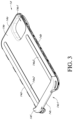
- FIG. 3 depicted therein is a top perspective view of front assembly 14 of case system 10 .
- Front assembly 14 Depicted implementation of front assembly 14 is shown to include side 14 a , side 14 b , side 14 c with cutout feature 14 c 1 , side 14 d , base 14 e with aperture 14 e 1 and strip 14 e 2 , and front 14 f .
- side 14 a , side 14 b , and side 14 d include snap-fit engagement members to engage with snap-fit engagement members of rear assembly 20 .
- FIG. 4 depicted therein is a top perspective view of electronics assembly 16 of case system 10 .
- electronics assembly 16 is shown to include battery assembly 16 a , electrical cabling 16 b , circuit board 16 c with first aperture 16 c 1 , second aperture 16 c 2 , first fastener 16 c 3 , and second fastener 16 c 4 .
- Depicted implementation of electronics assembly 16 is shown to include electrical connector assembly 16 d with connector 16 d 1 , circumference portion 16 d 2 , port portion 16 d 3 , plate 16 d 4 , contact 16 d 5 , and contact 16 d 6 , and electrical cabling 16 d 7 .
- gasket member 18 of case system 10 .
- Depicted implementation of gasket member 18 is shown to include linear portion 18 a , linear portion 18 b , linear portion 18 c , linear portion 18 d , curvilinear portion 18 e , curivilinear portion 18 f , curvilinear portion 18 g , linear portion 18 h , linear portion 18 i , curvilinear portion 18 j , curvilinear portion 18 k , curvilinear portion 18 l , curvilinear portion 18 m , and linear portion 18 n .
- gasket member 18 can be made from one or more of the following materials: closed-cell sponge rubber, open-cell sponge rubber, and foam material.
- FIG. 6 depicted therein is a top perspective view of rear assembly 20 of case system 10 .
- Depicted implementation of rear assembly 20 is shown to include channel portion 20 g 1 , channel portion 20 g 2 , channel portion 20 g 3 , channel portion 20 g 4 , channel portion 20 g 5 , channel portion 20 g 6 , channel portion 20 g 7 , channel portion 20 g 8 , channel portion 20 g 9 , channel portion 20 g 10 , channel portion 20 g 11 , channel portion 20 g 12 , and channel portion 20 g 13 .
- FIG. 7 depicted therein is a top plan view of rear assembly 20 coupled with gasket member 18 of case system 10 .
- FIG. 8 depicted therein is a top perspective view of rear assembly 20 of case system 10 .
- Depicted implementation of rear assembly 20 is shown to include side 20 a with cutout feature 20 a 1 , side 20 b , side 20 c , side 20 d , base interior 20 e with aperture 20 e 1 with rim portion 20 e 1 a , base portion 20 e 2 , base portion 20 e 3 , fastener receiver 20 e 4 , connector aperture 20 e 5 , connector aperture 20 e 6 , plate aperture 20 e 7 , base portion 20 e 8 , and base portion 20 e 9 .
- rear assembly 20 Depicted implementation of rear assembly 20 is shown to include interior wall 20 f 1 , interior wall 20 f 2 , interior wall 20 f 3 , interior wall 20 f 8 , and interior wall 20 f 9 that in part define walled portions or walled compartments.
- side 20 a , side 20 b , and side 20 d include snap-fit engagement members to engage with snap-fit engagement members of front assembly 14 .
- portions of base interior 20 e such as base portion 20 e 2 can be coated with one or more epoxy sealant layers.
- FIG. 9 depicted therein is a top perspective view of rear assembly 20 of case system 10 .
- Depicted implementation of rear assembly 20 is shown to include interior wall 20 f 4 , which helps to define a walled portion or walled compartment.
- FIG. 9 A depicted therein is a top perspective view of rear assembly 20 of case system 10 .
- FIG. 10 depicted therein is a top perspective view of card reader 22 of case system 10 .
- Depicted implementation of rear assembly 20 is shown to include side 22 a with swipe slot 22 a 1 , side 22 b with port portion 22 b 1 , side 22 c with insertion slot 22 c 1 , side 22 d , base 22 e with contact 22 e 1 and magnetic portion 22 e 2 .
- FIG. 11 depicted therein is a top perspective view of card reader 22 of case system 10 .
- FIG. 12 depicted therein is a top perspective view of gasket member 18 and rear assembly 20 of case system 10 .
- FIG. 13 depicted therein is a top plan view of gasket member 18 and rear assembly 20 of case system 10 .
- FIG. 14 depicted therein is a top perspective view of electronics assembly 16 , gasket member 18 , and rear assembly 20 of case system 10 .
- FIG. 15 depicted therein is a top perspective cross-sectional view of electronics assembly 16 , gasket member 18 , and rear assembly 20 of case system 10 .
- FIG. 16 depicted therein is a top perspective view of front assembly 14 , electronics assembly 16 , and rear assembly 20 of case system 10 . As depicted, front assembly 14 , and rear assembly 20 couple to form an opening sized to couple with electronics assembly 16 .
- FIG. 17 depicted therein is a top perspective view of bezel assembly 12 , front assembly 14 , electronics assembly 16 , and rear assembly 20 of case system 10 .
- FIG. 18 depicted therein is a top perspective view of case system 10 .
- FIG. 19 depicted therein is a top perspective view of case system 10 .
- FIG. 20 depicted therein is an exploded bottom perspective view of case system 10 .
- FIG. 21 depicted therein is a bottom perspective view of bezel assembly 12 of case system 10 .
- Depicted implementation of bezel assembly 12 is shown to include aperture 12 c 2 .
- FIG. 22 depicted therein is a bottom perspective view of front assembly 14 of case system 10 .
- Front assembly 14 Depicted implementation of front assembly 14 is shown to include rim portion 14 e 3 , recess portion 14 e 4 , first recess 14 e 5 , second recess 14 e 6 , base portion 14 e 7 , base portion 14 e 8 , and base portion 14 e 9 .
- FIG. 23 depicted therein is a bottom perspective view of electronics assembly 16 of case system 10 .
- electronics assembly 16 is shown to include cabling portion 16 c 8 , metallic portion 16 c 9 (such as a metal plate), electrical connector assembly 16 c 10 , electrical connector assembly 16 c 11 , protrusion 16 c 12 , and aperture 16 c 13 .
- electrical connector assembly 16 c 10 and electrical connector assembly 16 c 11 both have similar spatial arrangements of electrical contacts positioned along a row, which allows for contact 22 e 1 of card reader 22 to be electrically coupled with electrical connector assembly 16 c 10 when card reader 22 is coupled to rear assembly 20 in a first position (such as shown in FIG. 39 ) and to be electrically coupled with electrical connector assembly 16 c 11 when card reader 22 is coupled to rear assembly 20 in a second position 180 degrees from the first position (such as shown in FIG. 38 ).
- FIG. 24 depicted therein is a bottom perspective view of gasket member 18 of case system 10 .
- FIG. 25 depicted therein is a bottom perspective view of rear assembly 20 of case system 10 .
- Depicted implementation of rear assembly 20 is shown to include base exterior 20 h with recess 20 h 1 .
- Depicted implementation of recess 20 h 1 is shown to include side 20 h 1 a , side 20 h 1 b .
- side 20 h 1 c side 20 h 1 d
- base 20 h 1 e As depicted, connector aperture 20 e 5 (see FIG. 8 ) and connector aperture 20 e 6 (see FIG. 8 ) are equally spaced from side 20 h 1 b and side 20 h 1 d.
- FIG. 26 depicted therein is a bottom perspective view of card reader 22 of case system 10 .
- FIG. 27 depicted therein is an exploded bottom perspective view of case system 10 .
- FIG. 28 depicted therein is a bottom perspective view of bezel assembly 12 of case system 10 .
- FIG. 29 depicted therein is a bottom perspective view of front assembly 14 of case system 10 .
- FIG. 30 depicted therein is a bottom perspective view of electronics assembly 16 of case system 10 .
- FIG. 31 depicted therein is a bottom perspective view of gasket member 18 of case system 10 .
- FIG. 32 depicted therein is a bottom perspective view of rear assembly 20 of case system 10 .
- FIG. 33 depicted therein is a bottom perspective view of card reader 22 of case system 10 .
- FIG. 34 depicted therein is a bottom plan view of gasket member 18 and rear assembly 20 of case system 10 .
- FIG. 35 depicted therein is a top perspective view of electronics assembly 16 and rear assembly 20 of case system 10 .
- portions of electrical connector assembly 16 c 10 and electrical connector assembly 16 c 11 protrude through connector aperture 20 e 5 and connector aperture 20 e 6 , respectively, to be accessed from base exterior 20 h of rear assembly 20 .
- metallic portion 16 c 9 is protruding through plate aperture 20 e 7 (see FIG. 8 ) to be accessed from base exterior 20 h of rear assembly 20 .
- electrical connector assembly 16 c 10 and electrical connector assembly 16 c 11 both have a spatial arrangement of electrical contacts positioned along a row. As depicted in FIG. 35 , the electrical contacts on a first end of each of the two rows of electrical connector assembly 16 c 10 and electrical connector assembly 16 c 11 that are closest to side 20 b (see FIG. 8 ) are equidistant from side 20 b . As depicted in FIG. 35 , the electrical contacts on a second end of each of the two rows of electrical connector assembly 16 c 10 and electrical connector assembly 16 c 11 that are closest to side 20 d (see FIG. 8 ) are equidistant from side 20 d . As depicted, electrical connector assembly 16 c 10 and electrical connector assembly 16 c 11 are similarly positioned with respect to metallic portion 16 c 9 (see FIG. 23 ) as protruding through plate aperture 20 e 7 (see FIG. 8 ).
- FIG. 36 depicted therein is a top perspective view of front assembly 14 , electronics assembly 16 , and rear assembly 20 of case system 10 .
- FIG. 37 depicted therein is a top perspective view of bezel assembly 12 , electronics assembly 16 , and rear assembly 20 of case system 10 .
- FIG. 38 depicted therein is a bottom perspective view of case system 10 .
- FIG. 39 depicted therein is a bottom perspective view of case system 10 .
- FIG. 40 depicted therein is a bottom perspective view of case system 10 .
- FIG. 41 depicted therein is a bottom perspective view of case system 10 .
- FIG. 42 depicted therein is a side-elevational cross-sectional exploded view of case system 10 .
- FIG. 43 depicted therein is a side-elevational cross-sectional view of case system 10 .
- insertion slot 22 c 1 (see FIG. 45 ) of card reader 22
- swipe slot 22 a 1 (see FIG. 47 ) of card reader 22 are positioned an elevational distance from base 20 h 1 e of recess 20 h 1 by the depth of recess 20 h 1 .
- FIG. 44 depicted therein is an enlarged side-elevational cross-sectional exploded partial view of case system 10 .
- Depicted implementation of side 20 h 1 a is shown to include lip protrusion 20 h 1 a 1 , which is couplable with card reader 22 .
- FIG. 45 depicted therein is an enlarged side-elevational cross-sectional partial view of case system 10 .
- FIG. 46 depicted therein is an enlarged side-elevational cross-sectional exploded partial view of case system 10 .
- Depicted implementation of side 20 h 1 c is shown to include lip protrusion 20 h 1 c 1 , which is couplable with card reader 22 .
- FIG. 47 depicted therein is an enlarged side-elevational cross-sectional partial view of case system 10 .
- FIG. 48 depicted therein is a top perspective view of adapter 26 coupled with alternative card reader 24 .
- Depicted implementation of alternative card reader 24 is shown to include side 24 a , side 24 b , side 24 c , side 24 d , and exterior upper 24 e .
- Depicted implementation of adapter 26 is shown to include side 26 a , side 26 b , side 26 c , side 26 d , and exterior upper 26 e.
- FIG. 49 depicted therein is a bottom perspective view of adapter 26 coupled with alternative card reader 24 .
- Depicted implementation of adapter 26 is shown to include exterior lower 26 f with electrical contacts 26 f 1 and magnetic portion 26 f 2 .
- FIG. 50 depicted therein is a top perspective view of alternative card reader 24 coupled with adapter 26 coupled with case system 10 .
- FIG. 51 depicted therein is a side-elevational cross-sectional exploded view of alternative card reader 24 uncoupled from adapter 26 uncoupled from case system 10 .
- FIG. 52 depicted therein is a side-elevational cross-sectional view of alternative card reader 24 coupled with adapter 26 coupled with case system 10 .
- FIG. 53 depicted therein is an enlarged side-elevational cross-sectional exploded partial view of case system 10 uncoupled from adapter 26 .
- Depicted implementation of side 26 c is shown to include protrusion 26 c 1 .
- FIG. 54 depicted therein is an enlarged side-elevational cross-sectional exploded partial view of case system 10 coupled with adapter 26 including protrusion 26 c 1 of adapter 26 coupled with lip protrusion 20 h 1 a 1 of rear assembly 20
- FIG. 55 depicted therein is an enlarged side-elevational cross-sectional exploded partial view of case system 10 uncoupled from adapter 26 .
- Depicted implementation of side 26 a is shown to include protrusion 26 a 1 .
- FIG. 56 depicted therein is an enlarged side-elevational cross-sectional exploded partial view of case system 10 coupled with adapter 26 including protrusion 26 a 1 of adapter 26 coupled with lip protrusion 20 h 1 c 1 of rear assembly 20
- FIG. 57 depicted therein is a side-elevational cross-sectional view of alternative card reader 24 uncoupled from adapter 26 .
- Depicted implementation of side 24 c is shown to include insert slot 24 c 1 and.
- Depicted implementation of side 26 c is shown to include base 26 c 2 and side 26 c 3 .
- FIG. 58 depicted therein is a side-elevational cross-sectional view of alternative card reader 24 coupled with adapter 26 including side 26 c of adapter 26 coupled with side 24 c of alternative card reader 24 .
- a portion of insert slot 24 c 1 of alternative card reader 24 is positioned an elevational distance from base 26 c 2 of adapter 26 by the depth of side 26 c 3 .
- FIG. 59 depicted therein is a side-elevational cross-sectional view of alternative card reader 24 uncoupled from adapter 26 .
- side 24 a Depicted implementation of side 24 a is shown to include aperture 24 a 1 , exterior portion 24 a 2 , exterior portion 24 a 3 , exterior portion 24 a 4 , and exterior portion 24 a 5 .
- side 26 a Depicted implementation of side 26 a is shown to include protrusion 26 a 1 , interior portion 26 a 2 , interior portion 26 a 3 , interior portion 26 a 4 , and interior portion 26 a 5 .
- adapter 26 Depicted implementation of adapter 26 is shown to include electrical connector 26 g.
- FIG. 60 depicted therein is a side-elevational cross-sectional view of alternative card reader 24 coupled with adapter 26 including side 26 a of adapter 26 coupled with side 24 a of alternative card reader 24 .
Abstract
A case system includes first and second electrical connector assemblies coupled to an exterior side of a recess of a base of a rear assembly. The recess is couplable to a card reader so that the card reader when in a first position electrically couples to the first electrical connector assembly and when in a second position is oriented 180 degrees from the first position to electrically couple to the second electrical connector assembly. Other aspects are described in the claims, drawings, and text forming a part of the present disclosure.
Description
In one or more aspects a case system for a portable electronic device includes (I) a front assembly including (A) a first side, (B) a second side, (C) a third side, (D) a fourth side, and (E) a base extending perpendicular to and extending between the first side, the second side, the third side, and the fourth side, wherein at least a portion of the first side extends parallel to at least a portion of the second side, wherein at least a portion of the third side extends parallel to at least a portion of the fourth side, and wherein at least the portion of the first side extends perpendicular to the at least a portion of the third side; (II) a rear assembly coupled to the front assembly, the rear assembly including (A) a first side, (B) a second side, (C) a third side, (D) a fourth side, and (E) a base extending perpendicular to and extending between the first side, the second side, the third side, and the fourth side, wherein the base includes an interior side facing the front assembly and an exterior side facing away from the front assembly, wherein at least a portion of the first side extends parallel to at least a portion of the second side, wherein at least a portion of the third side extends parallel to at least a portion of the fourth side, and wherein at least the portion of the first side extends perpendicular to the at least a portion of the third side; (III) a first electrical connector assembly coupled with the base of the rear assembly, wherein the first electrical connector assembly includes a first plurality of electrical contacts positioned in a spatial arrangement, wherein the first plurality of electrical contacts is accessible from the exterior side of the base of the rear assembly, wherein the first plurality of electrical contacts includes an electrical contact nearest to the at least a portion of the first side of the rear assembly, wherein the electrical contact of the first plurality of electrical contacts nearest to the at least a portion of the first side of the rear assembly is spaced from the at least a portion of the first side of the rear assembly a first distance, wherein the first plurality of electrical contacts includes an electrical contact nearest to the at least a portion of the second side of the rear assembly, wherein the electrical contact of the first plurality of electrical contacts nearest to the at least a portion of the second side of the rear assembly is spaced from the at least a portion of the second side a second distance; and (IV) a second electrical connector assembly coupled with the base of the rear assembly, wherein the second electrical connector assembly includes a second plurality of electrical contacts positioned in a spatial arrangement, wherein the second plurality of electrical contacts is accessible from the exterior side of the base of the rear assembly, wherein the second plurality of electrical contacts includes an electrical contact nearest to the at least a portion of the first side of the rear assembly, wherein the electrical contact of the second plurality of electrical contacts nearest to the at least a portion of the first side of the rear assembly is spaced from the at least a portion of the first side of the rear assembly a first distance, wherein the second plurality of electrical contacts includes an electrical contact nearest to the at least a portion of the second side of the rear assembly, wherein the electrical contact of the second plurality of electrical contacts nearest to the at least a portion of the second side of the rear assembly is spaced from the at least a portion of the second side of the rear assembly a second distance, wherein in the first distance of the first electrical connector assembly is equal to the first distance of the second electrical connector assembly, wherein the second distance of the first electrical connector assembly is equal to the second distance of the second electrical connector assembly, and wherein the spatial arrangement of the second electrical connector assembly is a duplicate of the spatial arrangement of the first electrical connector assembly. Further including a third electrical connector assembly, wherein the rear assembly and the front assembly couple to form an opening sized to couple with the third electrical connector assembly. Wherein the base of the rear assembly includes a first aperture to receive the first electrical connector assembly, wherein a portion of the first electrical connector assembly protrudes through the first aperture from the interior side of the base to the exterior side of the base thereby providing accessibility to the plurality of electrical contacts of the first electrical connector assembly from the exterior side of the base, wherein the base of the rear assembly includes a second aperture to receive the second electrical connector assembly, and wherein a portion of the second electrical connector assembly protrudes through the second aperture from the interior side of the base to the exterior side of the base thereby providing accessibility to the plurality of electrical contacts of the second electrical connector assembly from the exterior side of the base. Wherein the exterior side of the base of the rear assembly includes a recess. Wherein the recess includes a base and a depth, wherein the exterior side of the base of the rear assembly includes a first portion and a second portion extending in parallel with respect to one another and differing in elevation by a first elevational difference, wherein the base of the recess is the first portion of the exterior side of the base, wherein the first elevational difference is the depth of the recess, and wherein the base of the recess includes the first aperture and the second aperture. Wherein the recess includes a first side, wherein the recess includes a second side, wherein the first side and the second side of the recess extend parallel with respect to one another, wherein the first aperture and the second aperture of the base of the rear assembly are equally spaced from the first side of the recess, and wherein the first aperture and the second aperture of the base of the rear assembly are equally spaced from the second side of the recess. Wherein the rear assembly includes a metal plate, wherein the metal plate is coupled to the base of the rear assembly, wherein the base of the recess includes a third aperture, and wherein a portion of the metal plate protrudes through the third aperture from the interior side of the base of the rear assembly to the base of the recess thereby providing accessibility to the metal plate from the exterior side of the base of the rear assembly. Wherein the third aperture of the base of the recess includes a first side and a second side extending parallel with one another, wherein the first plurality of electrical contacts of the first electrical connector assembly includes an electrical contact nearest to the first side of the third aperture, wherein the electrical contact of the first plurality of electrical contacts of the first electrical connector assembly nearest to the first side of the third aperture is spaced from the first side of the recess a first distance, wherein the second plurality of electrical contacts of the second electrical connector assembly includes an electrical contact nearest to the second side of the third aperture, and wherein the electrical contact of the second plurality of electrical contacts of the second electrical connector assembly nearest to the second side of the third aperture is spaced from the second side of the third aperture a second distance equal to the first distance. Wherein the recess includes at least one first lip protrusion extending from the first side of the recess, and wherein the recess includes at least one second lip protrusion extending from the second side of the recess. Further including a card reader including a base and at least one slot, wherein the card reader is couplable with the at least one first lip protrusion and the at least one second lip protrusion of the recess, wherein the at least one slot of the card reader extends in parallel with respect to the base of the card reader, wherein the at least one slot of the card reader is positioned a first elevational distance from base of the card reader, and wherein the depth of the recess of the rear assembly is equal to the first elevational distance. Further including an adapter sized and shaped to engage the at least one of lip protrusion extending from the first side of the recess and to engage the at least one of lip protrusion extending from the second side of the recess. Further including a card reader wherein the adapter is sized and shaped to couple with the card reader. Wherein the card reader includes a base and at least one slot, wherein the adapter includes a base positioned a first elevational distance from the at least one slot of the card reader when the adapter is coupled with the card reader, and wherein the depth of the recess of the rear assembly is equal to the first elevational distance. Wherein the card reader is electrically coupled with the first electrical connector assembly when the card reader is coupled to the rear assembly in a first position, wherein the card reader is electrically coupled with the second electrical connector assembly when the card reader is coupled to the rear assembly in a second position, and wherein the carder reader is rotationally oriented in the second position 180 degrees from the first position.
In one or more aspects a case including for a portable electronic device including (I) a front assembly; (II) a rear assembly coupled to the front assembly, the rear assembly including (A) a base including an edge, an interior side facing the front assembly and an exterior side facing away from the front assembly; (III) a first electrical connector assembly coupled with the base of the rear assembly, wherein the first electrical connector assembly includes a first plurality of electrical contacts positioned in a spatial arrangement, and wherein the first plurality of electrical contacts is accessible from the exterior side of the base; and (IV) a second electrical connector assembly coupled with the base of the rear assembly, wherein the second electrical connector assembly includes a second plurality of electrical contacts positioned in a spatial arrangement, wherein the second plurality of electrical contacts is accessible from the exterior side of the base, wherein the spatial arrangement of the second electrical connector assembly is a duplicate of the spatial arrangement of the first electrical connector assembly, and wherein the first electrical connector assembly and the second electrical connector assembly are spaced from the edge of the base a first distance. Wherein the exterior side of the base of the rear assembly includes a recess, wherein the rear assembly includes a metal plate coupled to the base of the rear assembly and accessible from the exterior side of the base of the rear assembly, and wherein from the exterior side of the base of the rear assembly the first electrical connector assembly and the second electrical connector assembly are equally spaced from opposite sides of the metal plate. Further including a card reader including a base and at least one slot, wherein the card reader is couplable with the recess, wherein the at least one slot of the card reader extends in parallel with respect to the base of the card reader, wherein the at least one slot of the card reader is positioned a first elevational distance from base of the card reader, and wherein the depth of the recess of the rear assembly is equal to the first elevational distance.
In one or more aspects a case including for a portable electronic device including (I) a rear assembly including (A) a base including an edge and an exterior side; (II) a first electrical connector assembly coupled with the base of the rear assembly and accessible from the exterior side of the base; and (III) a second electrical connector assembly coupled with the base of the rear assembly and accessible from the exterior side of the base, and wherein the first electrical connector assembly and the second electrical connector assembly are spaced from the edge of the base a first distance. Further including a card reader and an adapter, wherein the adapter is sized and shaped to couple with the card reader, wherein the exterior side of the base of the rear assembly includes a recess, wherein the adapter is sized and shaped to couple with the recess having a depth, wherein the card reader includes a base and at least one slot, wherein the adapter includes a base positioned a first elevational distance from the at least one slot of the card reader when the adapter is coupled with the card reader, and wherein the depth of the recess of the rear assembly is equal to the first elevational distance. further including a card reader couplable to the rear assembly, wherein the card reader is electrically coupled with the first electrical connector assembly when the card reader is coupled to the rear assembly in a first position, wherein the card reader is electrically coupled with the second electrical connector assembly when the card reader is coupled to the rear assembly in a second position, and wherein the carder reader is rotationally oriented in the second position 180 degrees from the first position.
In addition to the foregoing, other aspects are described in the claims, drawings, and text forming a part of the disclosure set forth herein. Various other aspects are set forth and described in the teachings such as text (e.g., claims and/or detailed description) and/or drawings of the present disclosure. The foregoing is a summary and thus may contain simplifications, generalizations, inclusions, or omissions of detail; consequently, those skilled in the art will appreciate that the summary is illustrative only and is NOT intended to be in any way limiting. Other aspects, features, and advantages of the devices and/or processes and/or other subject matter described herein will become apparent in the teachings set forth herein.
For a more complete understanding of implementations, reference now is made to the following descriptions taken in connection with the accompanying drawings. The use of the same symbols in different drawings typically indicates similar or identical items, unless context dictates otherwise.
With reference now to the figures, shown are one or more examples of Case System for Portable Electronic Device, articles of manufacture, compositions of matter for same that may provide context, for instance, in introducing one or more processes and/or devices described herein.
In the following detailed description, reference is made to the accompanying drawings, which form a part hereof. In the drawings, similar symbols typically identify similar components, unless context dictates otherwise. The illustrative implementations described in the detailed description, drawings, and claims are not meant to be limiting. Other implementations may be utilized, and other changes may be made, without departing from the spirit or scope of the subject matter presented here.
Turning to FIG. 1 , depicted therein is an exploded top perspective view of case system 10. Depicted implementation of case system 10 is shown to include bezel assembly 12, front assembly 14, electronics assembly 16, gasket member 18, rear assembly 20, and card reader 22.
Turning to FIG. 2 , depicted therein is a top perspective view of bezel assembly 12 of case system 10. Depicted implementation of bezel assembly 12 is shown to include side 12 a with catch 12 a 1, side 12 b with aperture 12 b 1, side 12 c with cutout feature 12 c 1, side 12 d with aperture 12 d 1, and front 12 e.
Turning to FIG. 3 , depicted therein is a top perspective view of front assembly 14 of case system 10. Depicted implementation of front assembly 14 is shown to include side 14 a, side 14 b, side 14 c with cutout feature 14 c 1, side 14 d, base 14 e with aperture 14 e 1 and strip 14 e 2, and front 14 f. As depicted, side 14 a, side 14 b, and side 14 d include snap-fit engagement members to engage with snap-fit engagement members of rear assembly 20.
Turning to FIG. 4 , depicted therein is a top perspective view of electronics assembly 16 of case system 10. Depicted implementation of electronics assembly 16 is shown to include battery assembly 16 a, electrical cabling 16 b, circuit board 16 c with first aperture 16 c 1, second aperture 16 c 2, first fastener 16 c 3, and second fastener 16 c 4. Depicted implementation of electronics assembly 16 is shown to include electrical connector assembly 16 d with connector 16 d 1, circumference portion 16 d 2, port portion 16 d 3, plate 16 d 4, contact 16 d 5, and contact 16 d 6, and electrical cabling 16 d 7.
Turning to FIG. 5 , depicted therein is a top perspective view of gasket member 18 of case system 10. Depicted implementation of gasket member 18 is shown to include linear portion 18 a, linear portion 18 b, linear portion 18 c, linear portion 18 d, curvilinear portion 18 e, curivilinear portion 18 f, curvilinear portion 18 g, linear portion 18 h, linear portion 18 i, curvilinear portion 18 j, curvilinear portion 18 k, curvilinear portion 18 l, curvilinear portion 18 m, and linear portion 18 n. As depicted, gasket member 18 can be made from one or more of the following materials: closed-cell sponge rubber, open-cell sponge rubber, and foam material.
Turning to FIG. 6 , depicted therein is a top perspective view of rear assembly 20 of case system 10. Depicted implementation of rear assembly 20 is shown to include channel portion 20 g 1, channel portion 20 g 2, channel portion 20 g 3, channel portion 20 g 4, channel portion 20 g 5, channel portion 20 g 6, channel portion 20 g 7, channel portion 20 g 8, channel portion 20 g 9, channel portion 20 g 10, channel portion 20 g 11, channel portion 20 g 12, and channel portion 20 g 13.
Turning to FIG. 7 , depicted therein is a top plan view of rear assembly 20 coupled with gasket member 18 of case system 10.
Turning to FIG. 8 , depicted therein is a top perspective view of rear assembly 20 of case system 10. Depicted implementation of rear assembly 20 is shown to include side 20 a with cutout feature 20 a 1, side 20 b, side 20 c, side 20 d, base interior 20 e with aperture 20 e 1 with rim portion 20 e 1 a, base portion 20 e 2, base portion 20 e 3, fastener receiver 20 e 4, connector aperture 20 e 5, connector aperture 20 e 6, plate aperture 20 e 7, base portion 20 e 8, and base portion 20 e 9. Depicted implementation of rear assembly 20 is shown to include interior wall 20 f 1, interior wall 20 f 2, interior wall 20 f 3, interior wall 20 f 8, and interior wall 20 f 9 that in part define walled portions or walled compartments. As depicted, side 20 a, side 20 b, and side 20 d include snap-fit engagement members to engage with snap-fit engagement members of front assembly 14. As depicted, portions of base interior 20 e such as base portion 20 e 2 can be coated with one or more epoxy sealant layers.
Turning to FIG. 9 , depicted therein is a top perspective view of rear assembly 20 of case system 10. Depicted implementation of rear assembly 20 is shown to include interior wall 20 f 4, which helps to define a walled portion or walled compartment.
Turning to FIG. 9A , depicted therein is a top perspective view of rear assembly 20 of case system 10.
Turning to FIG. 10 , depicted therein is a top perspective view of card reader 22 of case system 10. Depicted implementation of rear assembly 20 is shown to include side 22 a with swipe slot 22 a 1, side 22 b with port portion 22 b 1, side 22 c with insertion slot 22 c 1, side 22 d, base 22 e with contact 22 e 1 and magnetic portion 22 e 2.
Turning to FIG. 11 , depicted therein is a top perspective view of card reader 22 of case system 10.
Turning to FIG. 12 , depicted therein is a top perspective view of gasket member 18 and rear assembly 20 of case system 10.
Turning to FIG. 13 , depicted therein is a top plan view of gasket member 18 and rear assembly 20 of case system 10.
Turning to FIG. 14 , depicted therein is a top perspective view of electronics assembly 16, gasket member 18, and rear assembly 20 of case system 10.
Turning to FIG. 15 , depicted therein is a top perspective cross-sectional view of electronics assembly 16, gasket member 18, and rear assembly 20 of case system 10.
Turning to FIG. 16 , depicted therein is a top perspective view of front assembly 14, electronics assembly 16, and rear assembly 20 of case system 10. As depicted, front assembly 14, and rear assembly 20 couple to form an opening sized to couple with electronics assembly 16.
Turning to FIG. 17 , depicted therein is a top perspective view of bezel assembly 12, front assembly 14, electronics assembly 16, and rear assembly 20 of case system 10.
Turning to FIG. 18 , depicted therein is a top perspective view of case system 10.
Turning to FIG. 19 , depicted therein is a top perspective view of case system 10.
Turning to FIG. 20 , depicted therein is an exploded bottom perspective view of case system 10.
Turning to FIG. 21 , depicted therein is a bottom perspective view of bezel assembly 12 of case system 10. Depicted implementation of bezel assembly 12 is shown to include aperture 12 c 2.
Turning to FIG. 22 , depicted therein is a bottom perspective view of front assembly 14 of case system 10. Depicted implementation of front assembly 14 is shown to include rim portion 14 e 3, recess portion 14 e 4, first recess 14 e 5, second recess 14 e 6, base portion 14 e 7, base portion 14 e 8, and base portion 14 e 9.
Turning to FIG. 23 , depicted therein is a bottom perspective view of electronics assembly 16 of case system 10. Depicted implementation of electronics assembly 16 is shown to include cabling portion 16 c 8, metallic portion 16 c 9 (such as a metal plate), electrical connector assembly 16 c 10, electrical connector assembly 16 c 11, protrusion 16 c 12, and aperture 16 c 13. As depicted, electrical connector assembly 16 c 10 and electrical connector assembly 16 c 11 both have similar spatial arrangements of electrical contacts positioned along a row, which allows for contact 22 e 1 of card reader 22 to be electrically coupled with electrical connector assembly 16 c 10 when card reader 22 is coupled to rear assembly 20 in a first position (such as shown in FIG. 39 ) and to be electrically coupled with electrical connector assembly 16 c 11 when card reader 22 is coupled to rear assembly 20 in a second position 180 degrees from the first position (such as shown in FIG. 38 ).
Turning to FIG. 24 , depicted therein is a bottom perspective view of gasket member 18 of case system 10.
Turning to FIG. 25 , depicted therein is a bottom perspective view of rear assembly 20 of case system 10. Depicted implementation of rear assembly 20 is shown to include base exterior 20 h with recess 20 h 1. Depicted implementation of recess 20 h 1 is shown to include side 20 h 1 a, side 20 h 1 b. side 20 h 1 c, side 20 h 1 d, and base 20 h 1 e. As depicted, connector aperture 20 e 5 (see FIG. 8 ) and connector aperture 20 e 6 (see FIG. 8 ) are equally spaced from side 20 h 1 b and side 20 h 1 d.
Turning to FIG. 26 , depicted therein is a bottom perspective view of card reader 22 of case system 10.
Turning to FIG. 27 , depicted therein is an exploded bottom perspective view of case system 10.
Turning to FIG. 28 , depicted therein is a bottom perspective view of bezel assembly 12 of case system 10.
Turning to FIG. 29 , depicted therein is a bottom perspective view of front assembly 14 of case system 10.
Turning to FIG. 30 , depicted therein is a bottom perspective view of electronics assembly 16 of case system 10.
Turning to FIG. 31 , depicted therein is a bottom perspective view of gasket member 18 of case system 10.
Turning to FIG. 32 , depicted therein is a bottom perspective view of rear assembly 20 of case system 10.
Turning to FIG. 33 , depicted therein is a bottom perspective view of card reader 22 of case system 10.
Turning to FIG. 34 , depicted therein is a bottom plan view of gasket member 18 and rear assembly 20 of case system 10.
Turning to FIG. 35 , depicted therein is a top perspective view of electronics assembly 16 and rear assembly 20 of case system 10. As depicted, portions of electrical connector assembly 16 c 10 and electrical connector assembly 16 c 11 protrude through connector aperture 20 e 5 and connector aperture 20 e 6, respectively, to be accessed from base exterior 20 h of rear assembly 20. As depicted, metallic portion 16 c 9 (see FIG. 23 ) is protruding through plate aperture 20 e 7 (see FIG. 8 ) to be accessed from base exterior 20 h of rear assembly 20.
As discussed above regarding FIG. 23 , electrical connector assembly 16 c 10 and electrical connector assembly 16 c 11 both have a spatial arrangement of electrical contacts positioned along a row. As depicted in FIG. 35 , the electrical contacts on a first end of each of the two rows of electrical connector assembly 16 c 10 and electrical connector assembly 16 c 11 that are closest to side 20 b (see FIG. 8 ) are equidistant from side 20 b. As depicted in FIG. 35 , the electrical contacts on a second end of each of the two rows of electrical connector assembly 16 c 10 and electrical connector assembly 16 c 11 that are closest to side 20 d (see FIG. 8 ) are equidistant from side 20 d. As depicted, electrical connector assembly 16 c 10 and electrical connector assembly 16 c 11 are similarly positioned with respect to metallic portion 16 c 9 (see FIG. 23 ) as protruding through plate aperture 20 e 7 (see FIG. 8 ).
Turning to FIG. 36 , depicted therein is a top perspective view of front assembly 14, electronics assembly 16, and rear assembly 20 of case system 10.
Turning to FIG. 37 , depicted therein is a top perspective view of bezel assembly 12, electronics assembly 16, and rear assembly 20 of case system 10.
Turning to FIG. 38 , depicted therein is a bottom perspective view of case system 10.
Turning to FIG. 39 , depicted therein is a bottom perspective view of case system 10.
Turning to FIG. 40 , depicted therein is a bottom perspective view of case system 10.
Turning to FIG. 41 , depicted therein is a bottom perspective view of case system 10.
Turning to FIG. 42 , depicted therein is a side-elevational cross-sectional exploded view of case system 10.
Turning to FIG. 43 , depicted therein is a side-elevational cross-sectional view of case system 10. As depicted, when card reader 22 is coupled with rear assembly 20, insertion slot 22 c 1 (see FIG. 45 ) of card reader 22 and swipe slot 22 a 1 (see FIG. 47 ) of card reader 22 are positioned an elevational distance from base 20 h 1 e of recess 20 h 1 by the depth of recess 20 h 1.
Turning to FIG. 44 , depicted therein is an enlarged side-elevational cross-sectional exploded partial view of case system 10. Depicted implementation of side 20 h 1 a is shown to include lip protrusion 20 h 1a1, which is couplable with card reader 22.
Turning to FIG. 45 , depicted therein is an enlarged side-elevational cross-sectional partial view of case system 10.
Turning to FIG. 46 , depicted therein is an enlarged side-elevational cross-sectional exploded partial view of case system 10. Depicted implementation of side 20 h 1 c is shown to include lip protrusion 20 h 1 c 1, which is couplable with card reader 22.
Turning to FIG. 47 , depicted therein is an enlarged side-elevational cross-sectional partial view of case system 10.
Turning to FIG. 48 , depicted therein is a top perspective view of adapter 26 coupled with alternative card reader 24. Depicted implementation of alternative card reader 24 is shown to include side 24 a, side 24 b, side 24 c, side 24 d, and exterior upper 24 e. Depicted implementation of adapter 26 is shown to include side 26 a, side 26 b, side 26 c, side 26 d, and exterior upper 26 e.
Turning to FIG. 49 , depicted therein is a bottom perspective view of adapter 26 coupled with alternative card reader 24. Depicted implementation of adapter 26 is shown to include exterior lower 26 f with electrical contacts 26 f 1 and magnetic portion 26 f 2.
Turning to FIG. 50 , depicted therein is a top perspective view of alternative card reader 24 coupled with adapter 26 coupled with case system 10.
Turning to FIG. 51 , depicted therein is a side-elevational cross-sectional exploded view of alternative card reader 24 uncoupled from adapter 26 uncoupled from case system 10.
Turning to FIG. 52 , depicted therein is a side-elevational cross-sectional view of alternative card reader 24 coupled with adapter 26 coupled with case system 10.
Turning to FIG. 53 , depicted therein is an enlarged side-elevational cross-sectional exploded partial view of case system 10 uncoupled from adapter 26. Depicted implementation of side 26 c is shown to include protrusion 26 c 1.
Turning to FIG. 54 , depicted therein is an enlarged side-elevational cross-sectional exploded partial view of case system 10 coupled with adapter 26 including protrusion 26 c 1 of adapter 26 coupled with lip protrusion 20 h 1a1 of rear assembly 20
Turning to FIG. 55 , depicted therein is an enlarged side-elevational cross-sectional exploded partial view of case system 10 uncoupled from adapter 26. Depicted implementation of side 26 a is shown to include protrusion 26 a 1.
Turning to FIG. 56 , depicted therein is an enlarged side-elevational cross-sectional exploded partial view of case system 10 coupled with adapter 26 including protrusion 26 a 1 of adapter 26 coupled with lip protrusion 20 h 1 c 1 of rear assembly 20
Turning to FIG. 57 , depicted therein is a side-elevational cross-sectional view of alternative card reader 24 uncoupled from adapter 26. Depicted implementation of side 24 c is shown to include insert slot 24 c 1 and. Depicted implementation of side 26 c is shown to include base 26 c 2 and side 26 c 3.
Turning to FIG. 58 , depicted therein is a side-elevational cross-sectional view of alternative card reader 24 coupled with adapter 26 including side 26 c of adapter 26 coupled with side 24 c of alternative card reader 24. As depicted, when alternative card reader 24 is coupled with adapter 26, a portion of insert slot 24 c 1 of alternative card reader 24 is positioned an elevational distance from base 26 c 2 of adapter 26 by the depth of side 26 c 3.
Turning to FIG. 59 , depicted therein is a side-elevational cross-sectional view of alternative card reader 24 uncoupled from adapter 26. Depicted implementation of side 24 a is shown to include aperture 24 a 1, exterior portion 24 a 2, exterior portion 24 a 3, exterior portion 24 a 4, and exterior portion 24 a 5. Depicted implementation of side 26 a is shown to include protrusion 26 a 1, interior portion 26 a 2, interior portion 26 a 3, interior portion 26 a 4, and interior portion 26 a 5. Depicted implementation of adapter 26 is shown to include electrical connector 26 g.
Turning to FIG. 60 , depicted therein is a side-elevational cross-sectional view of alternative card reader 24 coupled with adapter 26 including side 26 a of adapter 26 coupled with side 24 a of alternative card reader 24.
While particular aspects of the present subject matter described herein have been shown and described, it will be apparent to those skilled in the art that, based upon the teachings herein, changes and modifications may be made without departing from the subject matter described herein and its broader aspects and, therefore, the appended claims are to encompass within their scope all such changes and modifications as are within the true spirit and scope of the subject matter described herein. It will be understood by those within the art that, in general, terms used herein, and especially in the appended claims (e.g., bodies of the appended claims) are generally intended as “open” terms (e.g., the term “including” should be interpreted as “including but not limited to,” the term “having” should be interpreted as “having at least,” the term “includes” should be interpreted as “includes but is not limited to,” etc.). It will be further understood by those within the art that if a specific number of an introduced claim recitation is intended, such an intent will be explicitly recited in the claim, and in the absence of such recitation no such intent is present. For example, as an aid to understanding, the following appended claims may contain usage of the introductory phrases “at least one” and “one or more” to introduce claim recitations. However, the use of such phrases should not be construed to imply that the introduction of a claim recitation by the indefinite articles “a” or “an” limits any particular claim containing such introduced claim recitation to claims containing only one such recitation, even when the same claim includes the introductory phrases “one or more” or “at least one” and indefinite articles such as “a” or “an” (e.g., “a” and/or “an” should typically be interpreted to mean “at least one” or “one or more”); the same holds true for the use of definite articles used to introduce claim recitations. In addition, even if a specific number of an introduced claim recitation is explicitly recited, those skilled in the art will recognize that such recitation should typically be interpreted to mean at least the recited number (e.g., the bare recitation of “two recitations,” without other modifiers, typically means at least two recitations, or two or more recitations). Furthermore, in those instances where a convention analogous to “at least one of A, B, and C, etc.” is used, in general such a construction is intended in the sense one having skill in the art would understand the convention (e.g., “a system having at least one of A, B, and C” would include but not be limited to systems that have A alone, B alone, C alone, A and B together, A and C together, B and C together, and/or A, B, and C together, etc.). In those instances where a convention analogous to “at least one of A, B, or C, etc.” is used, in general such a construction is intended in the sense one having skill in the art would understand the convention (e.g., “a system having at least one of A, B, or C” would include but not be limited to systems that have A alone, B alone, C alone, A and B together, A and C together, B and C together, and/or A, B, and C together, etc.). It will be further understood by those within the art that typically a disjunctive word and/or phrase presenting two or more alternative terms, whether in the description, claims, or drawings, should be understood to contemplate the possibilities of including one of the terms, either of the terms, or both terms unless context dictates otherwise. For example, the phrase “A or B” will be typically understood to include the possibilities of “A” or “B” or “A and B.”
With respect to the appended claims, those skilled in the art will appreciate that recited operations therein may generally be performed in any order. Also, although various operational flows are presented in a sequence(s), it should be understood that the various operations may be performed in other orders than those which are illustrated, or may be performed concurrently. Examples of such alternate orderings may include overlapping, interleaved, interrupted, reordered, incremental, preparatory, supplemental, simultaneous, reverse, or other variant orderings, unless context dictates otherwise. Furthermore, terms like “responsive to,” “related to,” or other past-tense adjectives are generally not intended to exclude such variants, unless context dictates otherwise.
Claims (19)
1. A case system for a portable electronic device, the case system comprising:
(I) a front assembly including
(A) a first side,
(B) a second side,
(C) a third side,
(D) a fourth side, and
(E) a base extending perpendicular to and extending between the first side, the second side, the third side, and the fourth side,
wherein at least a portion of the first side extends parallel to at least a portion of the second side,
wherein at least a portion of the third side extends parallel to at least a portion of the fourth side, and
wherein at least the portion of the first side extends perpendicular to the at least a portion of the third side;
(II) a rear assembly coupled to the front assembly, the rear assembly including
(A) a first side
(B) a second side,
(C) a third side,
(D) a fourth side, and
(E) a base extending perpendicular to and extending between the first side, the second side, the third side, and the fourth side,
wherein the base includes an interior side facing the front assembly and an exterior side facing away from the front assembly,
wherein at least a portion of the first side extends parallel to at least a portion of the second side,
wherein at least a portion of the third side extends parallel to at least a portion of the fourth side, and
wherein at least the portion of the first side extends perpendicular to the at least a portion of the third side;
(III) a first electrical connector assembly coupled with the base of the rear assembly,
wherein the first electrical connector assembly includes a first plurality of electrical contacts positioned in a spatial arrangement,
wherein the first plurality of electrical contacts is accessible from the exterior side of the base of the rear assembly,
wherein the first plurality of electrical contacts includes an electrical contact nearest to the at least a portion of the first side of the rear assembly,
wherein the electrical contact of the first plurality of electrical contacts nearest to the at least a portion of the first side of the rear assembly is spaced from the at least a portion of the first side of the rear assembly a first distance,
wherein the first plurality of electrical contacts includes an electrical contact nearest to the at least a portion of the second side of the rear assembly,
wherein the electrical contact of the first plurality of electrical contacts nearest to the at least a portion of the second side of the rear assembly is spaced from the at least a portion of the second side a second distance; and
(IV) a second electrical connector assembly coupled with the base of the rear assembly,
wherein the second electrical connector assembly includes a second plurality of electrical contacts positioned in a spatial arrangement,
wherein the second plurality of electrical contacts is accessible from the exterior side of the base of the rear assembly,
wherein the second plurality of electrical contacts includes an electrical contact nearest to the at least a portion of the first side of the rear assembly,
wherein the electrical contact of the second plurality of electrical contacts nearest to the at least a portion of the first side of the rear assembly is spaced from the at least a portion of the first side of the rear assembly a first distance,
wherein the second plurality of electrical contacts includes an electrical contact nearest to the at least a portion of the second side of the rear assembly,
wherein the electrical contact of the second plurality of electrical contacts nearest to the at least a portion of the second side of the rear assembly is spaced from the at least a portion of the second side of the rear assembly a second distance,
wherein in the first distance of the first electrical connector assembly is equal to the first distance of the second electrical connector assembly,
wherein the second distance of the first electrical connector assembly is equal to the second distance of the second electrical connector assembly, and
wherein the spatial arrangement of the second electrical connector assembly is a duplicate of the spatial arrangement of the first electrical connector assembly.
2. The case system of claim 1 further including a third electrical connector assembly, wherein the rear assembly and the front assembly couple to form an opening sized to couple with the third electrical connector assembly.
3. The case system of claim 1
wherein the base of the rear assembly includes a first aperture to receive the first electrical connector assembly,
wherein a portion of the first electrical connector assembly protrudes through the first aperture from the interior side of the base to the exterior side of the base thereby providing accessibility to the plurality of electrical contacts of the first electrical connector assembly from the exterior side of the base,
wherein the base of the rear assembly includes a second aperture to receive the second electrical connector assembly, and
wherein a portion of the second electrical connector assembly protrudes through the second aperture from the interior side of the base to the exterior side of the base thereby providing accessibility to the plurality of electrical contacts of the second electrical connector assembly from the exterior side of the base.
4. The case system of claim 3
wherein the exterior side of the base of the rear assembly includes a recess.
5. The case system of claim 4
wherein the recess includes a base and a depth,
wherein the exterior side of the base of the rear assembly includes a first portion and a second portion extending in parallel with respect to one another and differing in elevation by a first elevational difference,
wherein the base of the recess is the first portion of the exterior side of the base,
wherein the first elevational difference is the depth of the recess, and
wherein the base of the recess includes the first aperture and the second aperture.
6. The case system of claim 5
wherein the recess includes a first side,
wherein the recess includes a second side,
wherein the first side and the second side of the recess extend parallel with respect to one another,
wherein the first aperture and the second aperture of the base of the rear assembly are equally spaced from the first side of the recess, and
wherein the first aperture and the second aperture of the base of the rear assembly are equally spaced from the second side of the recess.
7. The case system of claim 6
wherein the rear assembly includes a metal plate,
wherein the metal plate is coupled to the base of the rear assembly,
wherein the base of the recess includes a third aperture, and
wherein a portion of the metal plate protrudes through the third aperture from the interior side of the base of the rear assembly to the base of the recess thereby providing accessibility to the metal plate from the exterior side of the base of the rear assembly.
8. The case system of claim 7
wherein the third aperture of the base of the recess includes a first side and a second side extending parallel with one another,
wherein the first plurality of electrical contacts of the first electrical connector assembly includes an electrical contact nearest to the first side of the third aperture,
wherein the electrical contact of the first plurality of electrical contacts of the first electrical connector assembly nearest to the first side of the third aperture is spaced from the first side of the recess a first distance,
wherein the second plurality of electrical contacts of the second electrical connector assembly includes an electrical contact nearest to the second side of the third aperture, and
wherein the electrical contact of the second plurality of electrical contacts of the second electrical connector assembly nearest to the second side of the third aperture is spaced from the second side of the third aperture a second distance equal to the first distance.
9. The case system of claim 6
wherein the recess includes at least one first lip protrusion extending from the first side of the recess, and
wherein the recess includes at least one second lip protrusion extending from the second side of the recess.
10. The case system of claim 9 further including a card reader including a base and at least one slot,
wherein the card reader is couplable with the at least one first lip protrusion and the at least one second lip protrusion of the recess,
wherein the at least one slot of the card reader extends in parallel with respect to the base of the card reader,
wherein the at least one slot of the card reader is positioned a first elevational distance from base of the card reader, and
wherein the depth of the recess of the rear assembly is equal to the first elevational distance.
11. The case system of claim 9 further including an adapter sized and shaped to engage the at least one of lip protrusion extending from the first side of the recess and to engage the at least one of lip protrusion extending from the second side of the recess.
12. The case system of claim 11 further including a card reader wherein the adapter is sized and shaped to couple with the card reader.
13. The case system of claim 12
wherein the card reader includes a base and at least one slot,
wherein the adapter includes a base positioned a first elevational distance from the at least one slot of the card reader when the adapter is coupled with the card reader, and
wherein the depth of the recess of the rear assembly is equal to the first elevational distance.
14. The case system of claim 9 further including a card reader couplable to the rear assembly,
wherein the card reader is electrically coupled with the first electrical connector assembly when the card reader is coupled to the rear assembly in a first position,
wherein the card reader is electrically coupled with the second electrical connector assembly when the card reader is coupled to the rear assembly in a second position, and
wherein the carder reader is rotationally oriented in the second position 180 degrees from the first position.
15. A case system for a portable electronic device, the case system comprising:
(I) a front assembly;
(II) a rear assembly coupled to the front assembly, the rear assembly including
(A) a base including an edge, an interior side facing the front assembly and an exterior side facing away from the front assembly;
(III) a first electrical connector assembly coupled with the base of the rear assembly,
wherein the first electrical connector assembly includes a first plurality of electrical contacts positioned in a spatial arrangement, and
wherein the first plurality of electrical contacts is accessible from the exterior side of the base; and
(IV) a second electrical connector assembly coupled with the base of the rear assembly,
wherein the second electrical connector assembly includes a second plurality of electrical contacts positioned in a spatial arrangement,
wherein the second plurality of electrical contacts is accessible from the exterior side of the base,
wherein the spatial arrangement of the second electrical connector assembly is a duplicate of the spatial arrangement of the first electrical connector assembly, and
wherein the first electrical connector assembly and the second electrical connector assembly are spaced from the edge of the base a first distance.
16. The case system of claim 15
wherein the exterior side of the base of the rear assembly includes a recess,
wherein the rear assembly includes a metal plate coupled to the base of the rear assembly and accessible from the exterior side of the base of the rear assembly, and
wherein from the exterior side of the base of the rear assembly the first electrical connector assembly and the second electrical connector assembly are equally spaced from opposite sides of the metal plate.
17. The case system of claim 16 further including a card reader including a base and at least one slot,
wherein the card reader is couplable with the recess,
wherein the at least one slot of the card reader extends in parallel with respect to the base of the card reader,
wherein the at least one slot of the card reader is positioned a first elevational distance from base of the card reader, and
wherein the depth of the recess of the rear assembly is equal to the first elevational distance.
18. A case system for a portable electronic device, the case system comprising:
(I) a rear assembly including
(A) a base including an edge and an exterior side;
(II) a first electrical connector assembly coupled with the base of the rear assembly and accessible from the exterior side of the base;
(III) a second electrical connector assembly coupled with the base of the rear assembly and accessible from the exterior side of the base, and
wherein the first electrical connector assembly and the second electrical connector assembly are spaced from the edge of the base a first distance;
(IV) a card reader; and
(V) an adapter,
wherein the adapter is sized and shaped to couple with the card reader,
wherein the exterior side of the base of the rear assembly includes a recess,
wherein the adapter is sized and shaped to couple with the recess having a depth,
wherein the card reader includes a base and at least one slot,
wherein the adapter includes a base positioned a first elevational distance from the at least one slot of the card reader when the adapter is coupled with the card reader, and
wherein the depth of the recess of the rear assembly is equal to the first elevational distance.
19. A case system for a portable electronic device, the case system comprising:
(I) a rear assembly including
(A) a base including an edge and an exterior side;
(II) a first electrical connector assembly coupled with the base of the rear assembly and accessible from the exterior side of the base;
(III) a second electrical connector assembly coupled with the base of the rear assembly and accessible from the exterior side of the base, and
wherein the first electrical connector assembly and the second electrical connector assembly are spaced from the edge of the base a first distance; and
(IV) a card reader couplable to the rear assembly,
wherein the card reader is electrically coupled with the first electrical connector assembly when the card reader is coupled to the rear assembly in a first position, and
wherein the card reader is electrically coupled with the second electrical connector assembly when the card reader is coupled to the rear assembly in a second position in which the carder reader is rotationally oriented in the second position 180 degrees from the first position.
Priority Applications (1)
| Application Number | Priority Date | Filing Date | Title |
|---|---|---|---|
| US18/503,164 US11936800B1 (en) | 2023-10-24 | 2023-11-06 | Case system for portable electronic device |
Applications Claiming Priority (2)
| Application Number | Priority Date | Filing Date | Title |
|---|---|---|---|
| US202318493714A | 2023-10-24 | 2023-10-24 | |
| US18/503,164 US11936800B1 (en) | 2023-10-24 | 2023-11-06 | Case system for portable electronic device |
Related Parent Applications (1)
| Application Number | Title | Priority Date | Filing Date |
|---|---|---|---|
| US202318493714A Continuation-In-Part | 2023-10-24 | 2023-10-24 |
Publications (1)
| Publication Number | Publication Date |
|---|---|
| US11936800B1 true US11936800B1 (en) | 2024-03-19 |
Family
ID=90245955
Family Applications (1)
| Application Number | Title | Priority Date | Filing Date |
|---|---|---|---|
| US18/503,164 Active US11936800B1 (en) | 2023-10-24 | 2023-11-06 | Case system for portable electronic device |
Country Status (1)
| Country | Link |
|---|---|
| US (1) | US11936800B1 (en) |
Citations (5)
| Publication number | Priority date | Publication date | Assignee | Title |
|---|---|---|---|---|
| US5532466A (en) * | 1992-10-20 | 1996-07-02 | Matsushita Electric Industrial Co., Ltd. | Portable electronic equipment |
| WO2015099502A1 (en) * | 2013-12-27 | 2015-07-02 | Samsung Electronics Co., Ltd. | Protective cover and electronic device having it |
| US9838520B2 (en) * | 2011-04-22 | 2017-12-05 | Mastercard International Incorporated Purchase | Magnetic stripe attachment and application for mobile electronic devices |
| US10320101B2 (en) * | 2015-06-10 | 2019-06-11 | Fairphone B.V. | Connector for an electronic device |
| US10397460B2 (en) * | 2011-01-28 | 2019-08-27 | Windy Place, Inc. | Lighting and power devices and modules |
-
2023
- 2023-11-06 US US18/503,164 patent/US11936800B1/en active Active
Patent Citations (5)
| Publication number | Priority date | Publication date | Assignee | Title |
|---|---|---|---|---|
| US5532466A (en) * | 1992-10-20 | 1996-07-02 | Matsushita Electric Industrial Co., Ltd. | Portable electronic equipment |
| US10397460B2 (en) * | 2011-01-28 | 2019-08-27 | Windy Place, Inc. | Lighting and power devices and modules |
| US9838520B2 (en) * | 2011-04-22 | 2017-12-05 | Mastercard International Incorporated Purchase | Magnetic stripe attachment and application for mobile electronic devices |
| WO2015099502A1 (en) * | 2013-12-27 | 2015-07-02 | Samsung Electronics Co., Ltd. | Protective cover and electronic device having it |
| US10320101B2 (en) * | 2015-06-10 | 2019-06-11 | Fairphone B.V. | Connector for an electronic device |
Similar Documents
| Publication | Publication Date | Title |
|---|---|---|
| US4092698A (en) | Protective case for electrical instruments on circuit boards | |
| US11602206B1 (en) | Case for portable electronic computing device | |
| US11300997B1 (en) | Case for portable electronic computing device | |
| US11769976B1 (en) | Charging system for portable electronic devices | |
| US11188121B2 (en) | Case for portable electronic computing device | |
| US10849397B1 (en) | Case for portable electronic computing tablet device | |
| US9075579B2 (en) | Mounting apparatus for expansion card | |
| US20100264787A1 (en) | Computer system with circuit board | |
| US11936800B1 (en) | Case system for portable electronic device | |
| US11855397B1 (en) | Stand with movable connector interface for portable electronic device | |
| US10466807B1 (en) | Keyboard | |
| US11805873B1 (en) | Stand for portable electronic device | |
| US11669128B1 (en) | Station for portable electronic computing devices | |
| US20170354050A1 (en) | Modular housing apparatus | |
| US8542496B2 (en) | Mounting device for expansion card | |
| US20040053524A1 (en) | Pick and place cover for multiple terminal electronic components | |
| US6567275B1 (en) | Modular stack device | |
| US20190045641A1 (en) | Display assembly with an internal casing | |
| US20090141437A1 (en) | System and method to attach bezel to display panel | |
| US11109502B2 (en) | Connector assembly with retainer for CPU | |
| US11442498B2 (en) | Universal bracket for multiple form factors of PCIe cards in OCP sled environments | |
| US20110215687A1 (en) | Apparatus with case | |
| CN210926572U (en) | Connector jig | |
| US11864337B1 (en) | Hub device for portable electronic device | |
| CN209733102U (en) | Drawer anti-falling device |
Legal Events
| Date | Code | Title | Description |
|---|---|---|---|
| FEPP | Fee payment procedure |
Free format text: ENTITY STATUS SET TO UNDISCOUNTED (ORIGINAL EVENT CODE: BIG.); ENTITY STATUS OF PATENT OWNER: SMALL ENTITY |
|
| FEPP | Fee payment procedure |
Free format text: ENTITY STATUS SET TO SMALL (ORIGINAL EVENT CODE: SMAL); ENTITY STATUS OF PATENT OWNER: SMALL ENTITY |
|
| STCF | Information on status: patent grant |
Free format text: PATENTED CASE |