US11934902B1 - Mounts for tracking devices - Google Patents
Mounts for tracking devices Download PDFInfo
- Publication number
- US11934902B1 US11934902B1 US18/453,117 US202318453117A US11934902B1 US 11934902 B1 US11934902 B1 US 11934902B1 US 202318453117 A US202318453117 A US 202318453117A US 11934902 B1 US11934902 B1 US 11934902B1
- Authority
- US
- United States
- Prior art keywords
- mount
- base
- cover
- housing
- seat
- Prior art date
- Legal status (The legal status is an assumption and is not a legal conclusion. Google has not performed a legal analysis and makes no representation as to the accuracy of the status listed.)
- Active
Links
Images


Classifications
-
- G—PHYSICS
- G06—COMPUTING OR CALCULATING; COUNTING
- G06K—GRAPHICAL DATA READING; PRESENTATION OF DATA; RECORD CARRIERS; HANDLING RECORD CARRIERS
- G06K19/00—Record carriers for use with machines and with at least a part designed to carry digital markings
- G06K19/06—Record carriers for use with machines and with at least a part designed to carry digital markings characterised by the kind of the digital marking, e.g. shape, nature, code
- G06K19/067—Record carriers with conductive marks, printed circuits or semiconductor circuit elements, e.g. credit or identity cards also with resonating or responding marks without active components
- G06K19/07—Record carriers with conductive marks, printed circuits or semiconductor circuit elements, e.g. credit or identity cards also with resonating or responding marks without active components with integrated circuit chips
- G06K19/077—Constructional details, e.g. mounting of circuits in the carrier
- G06K19/07749—Constructional details, e.g. mounting of circuits in the carrier the record carrier being capable of non-contact communication, e.g. constructional details of the antenna of a non-contact smart card
- G06K19/07758—Constructional details, e.g. mounting of circuits in the carrier the record carrier being capable of non-contact communication, e.g. constructional details of the antenna of a non-contact smart card arrangements for adhering the record carrier to further objects or living beings, functioning as an identification tag
Definitions
- the present disclosure relates to mounts for tracking devices.
- wireless tracking devices have become popular amongst consumers. Typically, wireless tracking devices are small and require additional hardware to be physically mounted or coupled to an object that a user desires to track. Consumers often use wireless tracking devices for keys, sports equipment, pets, electronic equipment, etc. In some applications, keeping dirt, debris, and water away from the wireless tracking device is important, as is providing a housing for a tracking device that is rugged and holds up to impacts.
- Mounts for securing a device to an article comprise a housing and a coupler.
- the housing has an internal volume that is configured to selectively receive and retain the device in the housing.
- the coupler is attached to the housing and is configured to be operatively attached to the article.
- FIG. 1 illustrates an example use case for mounts according to the present disclosure.
- FIG. 2 is a schematic illustration representing mounts for tracking devices according to the present disclosure.
- FIG. 3 is an exploded isometric view of an example mount according to the present disclosure, shown with an AppleTM AirTagTM device for placement within the mount.
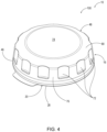
- FIG. 4 is an isometric view of the mount of FIG. 3 .
- FIG. 5 is a cross-sectional view of the mount of FIG. 3 .
- Mounts 10 for securing devices 12 to articles 14 are disclosed herein.
- devices 12 include wireless (e.g., WiFi, BluetoothTM, GPS) tracking devices (e.g., Apple AirTagTM, TileTM, Samsung Galaxy SmartTagTM, Chipolo OneTM, CubeProTM, OrbitTM, and BaseusTM branded tracking devices); and examples of articles 14 include sports equipment, snowboards, skis, skateboards, surfboards, paddle boards, stand-up paddle boards, wake boards, water skis, bicycles, hard-sided articles, land vehicles, trailers, All-Terrain-Vehicles (ATVs), motorcycles, watercraft, power tools, cases, luggage, camera gear, coolers, camping equipment, etc.
- mounts 10 may be used to secure a tracking device to an article 14 that a user desires to keep track of.
- FIG. 1 an example mount 10 is illustrated attached to a snowboard.
- FIG. 2 schematically illustrates mounts 10 according to the present disclosure.
- elements that are likely to be included in a given example are illustrated in solid lines, while elements that are optional to a given example or correspond to a specific example are illustrated in broken lines.
- elements that are illustrated in solid lines are not essential to all examples of the present disclosure, and an element shown in solid lines may be omitted from a particular example without departing from the scope of the present disclosure.
- positional terms such as “upper,” “lower,” and the like may be used to describe spatial relationships of elements of mounts 10 . When used, such terms refer to when a mount 10 is positioned to be operatively attached to the top of a horizontal surface, but does not limit mounts 10 to being secured to an article 14 in a specific orientation, such as on a horizontal surface thereof.
- mounts 10 generally comprise at least a housing 16 and a coupler 20 that is attached to the housing 16 .
- the housing 16 has an internal volume 18 that is configured to selectively receive and retain a device 12 , such as a tracking device, in the housing 16 .
- the coupler 20 is configured to be operatively attached to an article 14 .
- the coupler 20 is configured to be operatively attached to a planar surface of an article 14 , such as a planar surface of sports equipment. However, this is not required in all examples, and the coupler 20 may be configured to be operatively attached to a non-planar surface, such as a curved, convex, concave, or irregular surface, including being configured to mate with a very specific surface of a particular article 14 .
- the coupler 20 may be described as comprising an attachment surface 22 opposite the housing 16 , and the attachment surface 22 may be described as defining an attachment plane 24 .
- the attachment surface 22 is planar, although this is not required, and the attachment surface 22 may be textured or otherwise non-planar, yet still define an attachment plane 24 for operative attachment to a planar, textured, or non-planar surface of an article 14 .
- the coupler 20 may take various forms, such that it is configured to operatively attach to surface of an article 14 .
- the coupler 20 comprises an adhesive film 26 , such as double-sided tape.
- the coupler 20 comprises a double-sided foam tape 28 , such as having a foam core 29 sandwiched between two layers of double-sided tape or adhesive 31 .
- the foam core 29 provides a flexible attachment of the mount 10 to an article 14 , such that the foam core 29 will absorb impacts to the mount 10 and restrict inadvertent removal of the mount 10 from the article 14 .
- the foam core 29 enables the mount 10 to be attached to non-smooth, rough, non-flat, and/or curved surfaces of an article 14 , for example, with the foam core 29 enabling the lower double-sided tape or adhesive 31 to contour to the surface of the article 14 .
- the foam core 29 has a thickness in the range of 0.5-2 millimeters (mm); however, thicknesses outside of this range also may be used.
- a suitable example of a double-sided foam tape 28 that provides a strong attachment and restricts each removal of a mount 10 from an article 14 is 3MTM VHBTM double-sided tape.
- a coupler 20 is a magnet for operative attachment of the mount 10 to an article 14 having a magnetic (e.g., ferrous) surface, such as a vehicle.
- Mechanical fasteners e.g., screws, bolts, and the like
- the coupler 20 also may be or comprise an adhesive (e.g., glue) applied to the housing 16 for operative attachment to an article 14 .
- mounts 10 may be described as defining a central axis 30 .
- the mount 10 is substantially radially symmetrical about the central axis 30 .
- some mounts 10 may be described as having a generally circular profile.
- substantially radially symmetrical it is meant that the mount 10 is at least 75% radially symmetrical, such as being at least 75% round.
- the housing 16 may be described as defining a seat 32 within the internal volume 18 that is configured to mate with the device 12 .
- the seat 32 may be specifically shaped and sized to correspond to one or more surfaces of a specific device 12 , such as a specific tracking device.
- the seat 32 comprises a lower seat surface 34 that is configured to mate with the device 12 .
- the lower seat surface 34 may be concave, such as to mate with a convex surface of a particular device, such as an AppleTM AirTagTM device.
- the seat 32 comprises one or more seat ledges 36 that extend around the central axis 30 of the mount 10 , such as to engage a particular structure of a particular device 12 .
- a particular structure of a particular device 12 As an example, AppleTM AirTagTM devices have a lover convex surface surrounded by a circumferential planar surface. Accordingly, a seat 32 with a concave lower seat surface 34 and one or more seat ledges 36 extending around the central axis 30 of the mount 10 will mate with an AppleTM AirTagTM device.
- the internal volume 18 may be described as having a maximum internal-volume outer dimension 40
- the one or more seat ledges 36 may be described as defining an inside ledge diameter 38 that is less than the maximum internal-volume outer dimension 40 .
- a particular device 12 when operatively received within the internal volume 18 , a particular device 12 will extend over and engage the one or more seat ledges 36 .
- a plurality of radially spaced-apart seat ledges 36 are provided resulting in a reduced material cost and lighter weight housing 16 compared to examples where only one seat ledge 36 extends fully around the central axis 30 .
- the lower seat surface 34 likewise may be defined by a plurality of radially spaced surfaces that collectively define the lower seat surface 34 .
- the housing 16 may be described as having a housing outermost perimeter 42
- the coupler 20 may be described as having a coupler outermost perimeter 44 .
- the housing outermost perimeter 42 and the coupler outermost perimeter 44 are coextensive with each other.
- coextensive with each other it is meant that the housing outermost perimeter 42 and the coupler outermost perimeter 44 are within less than 1 mm of each other.
- the housing 16 may be described as comprising a ceiling surface 54 that defines an upper side of the internal volume 18 .
- the internal volume 18 is configured (e.g., shaped and sized) so that when the device 12 is operatively received in the internal volume 18 , there is a gap 56 between the device 12 and the ceiling surface 54 and the device 12 is fixed relative to the housing 16 . That is, the internal volume 18 may be configured to securely receive the device 12 , such that the device 12 does not move or rattle within the internal volume 18 , yet a gap 56 is present between the device 12 and the ceiling surface 54 .
- the device 12 has a maximum device height 50
- the internal volume 18 has a maximum internal-volume height 52 that is greater than the maximum device height 50 .
- Such a configuration may be advantageous for devices 12 that include a speaker or other sound transmitting mechanism on, near, or directed toward an upper surface of the device 12 .
- AppleTM AirTagTM devices have an internal speaker near the upper surface of the device. Accordingly, when operatively received within the internal volume 18 of such a configured mount 10 , the gap 56 facilitates transmission of the speaker's output, which otherwise would be diminished, or even muted, if the housing 16 firmly engaged the upper surface of the device.
- the housing 16 comprises a base 46 and a cover 48 .
- the coupler 20 is attached to the base 46
- the cover 48 is removably coupled to the base 46 to permit placement and removal of a device 12 in and from the internal volume 18 of the housing 16 .
- Various mechanisms for securing the cover 48 to the base 46 may be utilized depending on the application, or use case, for a particular mount 10 , including (but not limited to) snap-fit arrangements, friction-fit arrangements, threaded arrangements, mechanical fastener arrangements, etc.
- the cover 48 is threadingly coupled to the base 46 , and in some such examples, the cover 48 and the base 46 are configured to require at least a 90-degree rotation of the cover 48 relative to the base 46 for attachment and removal of the cover 48 to and from the base 46 .
- Such a configuration serves to restrict liquid, dust, or debris from disadvantageously entering the internal volume 18 when the cover 48 is operatively secured to the base 46 .
- the base 46 comprises a base sidewall 58 that extends upward from the lower seat surface 34 circumferentially around the central axis 30 .
- the cover 48 is threadingly coupled to the base 46
- the base sidewall 58 comprises an external thread 60
- the cover 48 comprises an internal thread 62 that is configured to mate with the external thread 60 of the base sidewall 58 .
- the cover 48 may be described as comprising a skirt 68 that extends circumferentially around the central axis 30 and that comprises the internal thread 62 , such that the skirt 68 and the base sidewall 58 collectively define the threaded arrangement between the cover 48 and the base 46 .
- the cover 48 comprises a rib 64 that extends downward from the ceiling surface 54 and circumferentially around the central axis 30 of the mount 10 .
- the rib 64 is positioned closer to the central axis 30 than the base sidewall 58 when the cover 48 is operatively coupled to the base 46 . Accordingly, in such examples, when the device 12 is operatively received within the internal volume 18 and the cover 48 is operatively coupled to the base 46 , the rib 64 will engage the device 12 and compress the device 12 between the rib 64 and the seat 32 .
- some devices 12 may comprise a spring-loaded battery compartment 55 , such that the device 12 is configured to compress in height.
- An AppleTM AirTagTM device is an example of such a device. Accordingly, when such a device 12 is operatively received within the internal volume 18 , and when the cover 48 is operatively coupled to the base 46 , the rib 64 will engage an upper surface of the device 12 and compress the device 12 between the rib 64 and the seat 32 , resulting in a snug fit of the device 12 within the internal volume 18 , such that the device is prevented from rattling or otherwise moving at all within the internal volume 18 . As a result, impacts or other movements of the mount 10 will not result in damage to the device 12 that otherwise could occur if the device 12 were not snugly received within the internal volume 18 .
- the housing 16 further comprises a gasket 66 that is positioned adjacent to the rib 64 and that is positioned to be compressed between the base sidewall 58 and the cover 48 when the cover 48 is operatively coupled to the base 46 .
- the gasket 66 therefor provides a liquid seal between the cover 48 and the base 46 to prevent liquid, as well as debris and dust, from entering the internal volume 18 and potentially damaging a device 12 held therein.
- the gasket 66 is positioned between the rib 64 and the skirt 68 .
- the gasket 66 is molded onto the cover 48 .
- the gasket 66 is an O-ring or a D-ring.
- the base 46 comprises a circumferential flange 70 that extends away from the central axis 30 of the mount 10 , and the cover 48 engages the circumferential flange 70 when the cover 48 is operatively coupled to the base 46 . Accordingly, this interface between the circumferential flange 70 and the cover 48 provides a first barrier between environment outside of the mount 10 and the internal volume 18 . Although not required, an additional or alternative gasket may be provided at this interface for an even greater barrier or seal.
- the circumferential flange 70 defines the housing outermost perimeter 42 , discussed above, which in some examples is coextensive with the coupler outermost perimeter 44 .
- the cover 48 defines a plurality of depressions 72 that are spaced around the central axis 30 of the mount 10 and that extend into the cover 48 toward the central axis 30 .
- depressions 72 provide a gripping structure for operative attachment and removal of the cover 48 to and from the base 46 .
- the surfaces of each depression may be at an angle between 180 and 225 degrees relative to one or more circumferentially adjacent surfaces of the cover 48 , such that no sharp edges are present that could catch on an object and result in the cover 48 inadvertently being unscrewed from the base 46 .
- the housing 16 (e.g., the cover 48 , when present) may be described as comprising a top surface 74 and an outer side surface 76 .
- the housing 16 has a chamfer 80 between the top surface 74 and the outer side surface 76 .
- the chamfer 80 may be described as a ramped surface for the deflection of objects.
- the outer side surface 76 may be an angle 78 of between 225 and 270 degrees to the top surface 74 .
- FIGS. 3 - 5 an illustrative non-exclusive example of a mount 10 in the form of mount 100 is illustrated.
- the reference numerals from the schematic illustration of FIG. 2 are used to designate corresponding parts of mount 100 ; however, the example of FIGS. 3 - 5 are non-exclusive and do not limit mounts 10 to the illustrated embodiment of mount 100 . That is, mounts 10 are not limited to the specific embodiment of the illustrated mount 100 , and mounts 10 may incorporate any number of the various aspects, configurations, characteristics, properties, etc. of mounts 10 that are illustrated in and discussed with reference to the schematic representations of FIG. 2 and/or the embodiment of FIGS.
- Mount 100 is specifically configured to receive an AppleTM AirTagTM device 12 , shown in FIG. 3 .
- mount 100 is an example of a mount 10 that is substantially symmetrical about its central axis 30 and that includes a cover 48 that is threadingly coupled to a base 46 .
- the coupler 20 of mount 100 comprises a double-sided foam tape 28 and is configured to operatively attach to a planar surface of an article 14 , such as a snowboard, as illustrated in FIG. 1 .
- the base 46 of mount 100 comprises a plurality of seat ledges 36 spaced radially about a concave lower seat surface 34 that is defined by a plurality of ribs that coincide with the seat ledges 36 .
- mount 100 is an example of a mount 10 whose base 46 comprises a base sidewall 58 comprising an external thread 60 and whose cover 48 comprises a skirt 68 that comprises an internal thread 62 .
- the cover 48 of mount 100 comprises a rib 64 that extends downward from the ceiling surface 54 of the cover 48 and that is spaced radially inward relative to the base sidewall 58 .
- the cover 48 When the cover 48 is operatively and completely threaded to the base 46 and when an AppleTM AirTagTM device 12 is operatively received within the internal volume 18 of the housing 16 , the rib 64 engages the upper surface of the AppleTM AirTagTM device 12 and compresses the battery compartment 55 of the AppleTM AirTagTM device against the plurality of seat ledges 36 . Moreover, a gap 56 is present between the AppleTM AirTagTM device and the ceiling surface 54 to permit transmission of the AppleTM AirTagTM device's emitted sounds.
- the terms “adapted” and “configured” mean that the element, component, or other subject matter is designed and/or intended to perform a given function. Thus, the use of the terms “adapted” and “configured” should not be construed to mean that a given element, component, or other subject matter is simply “capable of” performing a given function but that the element, component, and/or other subject matter is specifically selected, created, implemented, utilized, programmed, and/or designed for the purpose of performing the function. It is also within the scope of the present disclosure that elements, components, and/or other recited subject matter that is recited as being adapted to perform a particular function may additionally or alternatively be described as being configured to perform that function, and vice versa. Similarly, subject matter that is recited as being configured to perform a particular function may additionally or alternatively be described as being operative to perform that function.
- the term “and/or” placed between a first entity and a second entity means one of (1) the first entity, (2) the second entity, and (3) the first entity and the second entity.
- Multiple entries listed with “and/or” should be construed in the same manner, i.e., “one or more” of the entities so conjoined.
- Other entities optionally may be present other than the entities specifically identified by the “and/or” clause, whether related or unrelated to those entities specifically identified.
- a reference to “A and/or B,” when used in conjunction with open-ended language such as “comprising,” may refer, in one example, to A only (optionally including entities other than B); in another example, to B only (optionally including entities other than A); in yet another example, to both A and B (optionally including other entities).
- These entities may refer to elements, actions, structures, steps, operations, values, and the like.
Landscapes
- Engineering & Computer Science (AREA)
- Computer Hardware Design (AREA)
- Microelectronics & Electronic Packaging (AREA)
- Physics & Mathematics (AREA)
- General Physics & Mathematics (AREA)
- Theoretical Computer Science (AREA)
- Connection Of Plates (AREA)
- Casings For Electric Apparatus (AREA)
Abstract
Mounts (10) for securing a device (12) to an article (14) comprise a housing (16) having an internal volume (18) configured to selectively receive and retain the device (12) in the housing (16); and a coupler (20) attached to the housing (16) and configured to be operatively attached to the article (14).
Description
The present disclosure relates to mounts for tracking devices.
In recent years, wireless tracking devices have become popular amongst consumers. Typically, wireless tracking devices are small and require additional hardware to be physically mounted or coupled to an object that a user desires to track. Consumers often use wireless tracking devices for keys, sports equipment, pets, electronic equipment, etc. In some applications, keeping dirt, debris, and water away from the wireless tracking device is important, as is providing a housing for a tracking device that is rugged and holds up to impacts.
Mounts for securing a device to an article comprise a housing and a coupler. The housing has an internal volume that is configured to selectively receive and retain the device in the housing. The coupler is attached to the housing and is configured to be operatively attached to the article.
As schematically illustrated in FIG. 2 , mounts 10 generally comprise at least a housing 16 and a coupler 20 that is attached to the housing 16. The housing 16 has an internal volume 18 that is configured to selectively receive and retain a device 12, such as a tracking device, in the housing 16. The coupler 20 is configured to be operatively attached to an article 14.
In some examples, the coupler 20 is configured to be operatively attached to a planar surface of an article 14, such as a planar surface of sports equipment. However, this is not required in all examples, and the coupler 20 may be configured to be operatively attached to a non-planar surface, such as a curved, convex, concave, or irregular surface, including being configured to mate with a very specific surface of a particular article 14.
With continued reference to FIG. 2 , in some examples, the coupler 20 may be described as comprising an attachment surface 22 opposite the housing 16, and the attachment surface 22 may be described as defining an attachment plane 24. In some such examples, the attachment surface 22 is planar, although this is not required, and the attachment surface 22 may be textured or otherwise non-planar, yet still define an attachment plane 24 for operative attachment to a planar, textured, or non-planar surface of an article 14.
The coupler 20 may take various forms, such that it is configured to operatively attach to surface of an article 14. In some examples, the coupler 20 comprises an adhesive film 26, such as double-sided tape. In some examples, the coupler 20 comprises a double-sided foam tape 28, such as having a foam core 29 sandwiched between two layers of double-sided tape or adhesive 31. When present, the foam core 29 provides a flexible attachment of the mount 10 to an article 14, such that the foam core 29 will absorb impacts to the mount 10 and restrict inadvertent removal of the mount 10 from the article 14. In addition, the foam core 29 enables the mount 10 to be attached to non-smooth, rough, non-flat, and/or curved surfaces of an article 14, for example, with the foam core 29 enabling the lower double-sided tape or adhesive 31 to contour to the surface of the article 14. In some examples, the foam core 29 has a thickness in the range of 0.5-2 millimeters (mm); however, thicknesses outside of this range also may be used. A suitable example of a double-sided foam tape 28 that provides a strong attachment and restricts each removal of a mount 10 from an article 14 is 3M™ VHB™ double-sided tape. Another suitable example of a coupler 20 is a magnet for operative attachment of the mount 10 to an article 14 having a magnetic (e.g., ferrous) surface, such as a vehicle. Mechanical fasteners (e.g., screws, bolts, and the like) also may be used as couplers 20, depending on the use case of a particular mount 10. The coupler 20 also may be or comprise an adhesive (e.g., glue) applied to the housing 16 for operative attachment to an article 14.
As schematically represented in FIG. 2 , mounts 10 may be described as defining a central axis 30. In some examples, the mount 10 is substantially radially symmetrical about the central axis 30. For example, some mounts 10 may be described as having a generally circular profile. By “substantially radially symmetrical,” it is meant that the mount 10 is at least 75% radially symmetrical, such as being at least 75% round.
With continued reference to FIG. 2 , in some examples, the housing 16 may be described as defining a seat 32 within the internal volume 18 that is configured to mate with the device 12. In other words, the seat 32 may be specifically shaped and sized to correspond to one or more surfaces of a specific device 12, such as a specific tracking device. As a result, when a device 12 is operatively received within the internal volume 18, the device 12 will not undesirably rattle or move-around within the internal volume 18 when the mount 10 is moved. In some examples, the seat 32 comprises a lower seat surface 34 that is configured to mate with the device 12. As an example, the lower seat surface 34 may be concave, such as to mate with a convex surface of a particular device, such as an Apple™ AirTag™ device.
As schematically represented in FIG. 2 , in some examples, the seat 32 comprises one or more seat ledges 36 that extend around the central axis 30 of the mount 10, such as to engage a particular structure of a particular device 12. As an example, Apple™ AirTag™ devices have a lover convex surface surrounded by a circumferential planar surface. Accordingly, a seat 32 with a concave lower seat surface 34 and one or more seat ledges 36 extending around the central axis 30 of the mount 10 will mate with an Apple™ AirTag™ device.
In some examples, as schematically represented in FIG. 2 , the internal volume 18 may be described as having a maximum internal-volume outer dimension 40, and the one or more seat ledges 36 may be described as defining an inside ledge diameter 38 that is less than the maximum internal-volume outer dimension 40. Accordingly, in such examples, when operatively received within the internal volume 18, a particular device 12 will extend over and engage the one or more seat ledges 36. In some examples, a plurality of radially spaced-apart seat ledges 36 are provided resulting in a reduced material cost and lighter weight housing 16 compared to examples where only one seat ledge 36 extends fully around the central axis 30. In such examples where a plurality of seat ledges 36 are provided, the lower seat surface 34 likewise may be defined by a plurality of radially spaced surfaces that collectively define the lower seat surface 34.
With continued reference to FIG. 2 , in some examples, the housing 16 may be described as having a housing outermost perimeter 42, and the coupler 20 may be described as having a coupler outermost perimeter 44. In some such examples, the housing outermost perimeter 42 and the coupler outermost perimeter 44 are coextensive with each other. By “coextensive with each other,” it is meant that the housing outermost perimeter 42 and the coupler outermost perimeter 44 are within less than 1 mm of each other. When such examples of mounts 10 are operatively attached to an article 14, no gap will be present between the housing 16 and the article 14 that otherwise could be used to pry the housing 16 away from the article 14 and thus, detach the mount 10 from the article 14. That is, such mounts 10 may be described as being securely attached to an article 14 and thus, more secure than mounts that easily may be pried away from an article.
As schematically represented in FIG. 2 , in some examples, the housing 16 may be described as comprising a ceiling surface 54 that defines an upper side of the internal volume 18. In some such examples, the internal volume 18 is configured (e.g., shaped and sized) so that when the device 12 is operatively received in the internal volume 18, there is a gap 56 between the device 12 and the ceiling surface 54 and the device 12 is fixed relative to the housing 16. That is, the internal volume 18 may be configured to securely receive the device 12, such that the device 12 does not move or rattle within the internal volume 18, yet a gap 56 is present between the device 12 and the ceiling surface 54. Stated differently, in some examples, the device 12 has a maximum device height 50, and the internal volume 18 has a maximum internal-volume height 52 that is greater than the maximum device height 50. Such a configuration may be advantageous for devices 12 that include a speaker or other sound transmitting mechanism on, near, or directed toward an upper surface of the device 12. For example, Apple™ AirTag™ devices have an internal speaker near the upper surface of the device. Accordingly, when operatively received within the internal volume 18 of such a configured mount 10, the gap 56 facilitates transmission of the speaker's output, which otherwise would be diminished, or even muted, if the housing 16 firmly engaged the upper surface of the device.
With continued reference to FIG. 2 , in some examples of mounts 10, the housing 16 comprises a base 46 and a cover 48. The coupler 20 is attached to the base 46, and the cover 48 is removably coupled to the base 46 to permit placement and removal of a device 12 in and from the internal volume 18 of the housing 16. Various mechanisms for securing the cover 48 to the base 46 may be utilized depending on the application, or use case, for a particular mount 10, including (but not limited to) snap-fit arrangements, friction-fit arrangements, threaded arrangements, mechanical fastener arrangements, etc. In some examples, the cover 48 is threadingly coupled to the base 46, and in some such examples, the cover 48 and the base 46 are configured to require at least a 90-degree rotation of the cover 48 relative to the base 46 for attachment and removal of the cover 48 to and from the base 46. Such a configuration serves to restrict liquid, dust, or debris from disadvantageously entering the internal volume 18 when the cover 48 is operatively secured to the base 46.
In some examples, as schematically illustrated in FIG. 2 , the base 46 comprises a base sidewall 58 that extends upward from the lower seat surface 34 circumferentially around the central axis 30. In some such examples, in which the cover 48 is threadingly coupled to the base 46, the base sidewall 58 comprises an external thread 60, and the cover 48 comprises an internal thread 62 that is configured to mate with the external thread 60 of the base sidewall 58. In particular, the cover 48 may be described as comprising a skirt 68 that extends circumferentially around the central axis 30 and that comprises the internal thread 62, such that the skirt 68 and the base sidewall 58 collectively define the threaded arrangement between the cover 48 and the base 46.
With continued reference to FIG. 2 , in some examples, the cover 48 comprises a rib 64 that extends downward from the ceiling surface 54 and circumferentially around the central axis 30 of the mount 10. In some such examples, the rib 64 is positioned closer to the central axis 30 than the base sidewall 58 when the cover 48 is operatively coupled to the base 46. Accordingly, in such examples, when the device 12 is operatively received within the internal volume 18 and the cover 48 is operatively coupled to the base 46, the rib 64 will engage the device 12 and compress the device 12 between the rib 64 and the seat 32. For example, some devices 12 may comprise a spring-loaded battery compartment 55, such that the device 12 is configured to compress in height. An Apple™ AirTag™ device is an example of such a device. Accordingly, when such a device 12 is operatively received within the internal volume 18, and when the cover 48 is operatively coupled to the base 46, the rib 64 will engage an upper surface of the device 12 and compress the device 12 between the rib 64 and the seat 32, resulting in a snug fit of the device 12 within the internal volume 18, such that the device is prevented from rattling or otherwise moving at all within the internal volume 18. As a result, impacts or other movements of the mount 10 will not result in damage to the device 12 that otherwise could occur if the device 12 were not snugly received within the internal volume 18.
As schematically illustrated in FIG. 2 , in some examples, the housing 16 further comprises a gasket 66 that is positioned adjacent to the rib 64 and that is positioned to be compressed between the base sidewall 58 and the cover 48 when the cover 48 is operatively coupled to the base 46. The gasket 66 therefor provides a liquid seal between the cover 48 and the base 46 to prevent liquid, as well as debris and dust, from entering the internal volume 18 and potentially damaging a device 12 held therein. In some examples, the gasket 66 is positioned between the rib 64 and the skirt 68. In some examples, the gasket 66 is molded onto the cover 48. In other examples, the gasket 66 is an O-ring or a D-ring.
With continued reference to FIG. 2 , in some examples of mounts 10, the base 46 comprises a circumferential flange 70 that extends away from the central axis 30 of the mount 10, and the cover 48 engages the circumferential flange 70 when the cover 48 is operatively coupled to the base 46. Accordingly, this interface between the circumferential flange 70 and the cover 48 provides a first barrier between environment outside of the mount 10 and the internal volume 18. Although not required, an additional or alternative gasket may be provided at this interface for an even greater barrier or seal. In some examples, the circumferential flange 70 defines the housing outermost perimeter 42, discussed above, which in some examples is coextensive with the coupler outermost perimeter 44.
In some examples, as schematically represented in FIG. 2 , the cover 48 defines a plurality of depressions 72 that are spaced around the central axis 30 of the mount 10 and that extend into the cover 48 toward the central axis 30. When present, such depressions 72 provide a gripping structure for operative attachment and removal of the cover 48 to and from the base 46. In some such examples, the surfaces of each depression may be at an angle between 180 and 225 degrees relative to one or more circumferentially adjacent surfaces of the cover 48, such that no sharp edges are present that could catch on an object and result in the cover 48 inadvertently being unscrewed from the base 46.
With reference to FIG. 2 , the housing 16 (e.g., the cover 48, when present) may be described as comprising a top surface 74 and an outer side surface 76. In some examples of mounts 10, the housing 16 has a chamfer 80 between the top surface 74 and the outer side surface 76. As a result, there is no sharp angle (e.g., about 90 degrees) between two adjacent surfaces, so that if an object were to impact the housing 16, the object will more easily be deflected without damaging the mount 10 or inadvertently detaching the mount 10 from an article 14. That is, the chamfer 80 may be described as a ramped surface for the deflection of objects.
As schematically represented in FIG. 2 , in some examples, whether or not a chamfer 80 is present, the outer side surface 76 may be an angle 78 of between 225 and 270 degrees to the top surface 74.
Turning now to FIGS. 3-5 , an illustrative non-exclusive example of a mount 10 in the form of mount 100 is illustrated. Where appropriate, the reference numerals from the schematic illustration of FIG. 2 are used to designate corresponding parts of mount 100; however, the example of FIGS. 3-5 are non-exclusive and do not limit mounts 10 to the illustrated embodiment of mount 100. That is, mounts 10 are not limited to the specific embodiment of the illustrated mount 100, and mounts 10 may incorporate any number of the various aspects, configurations, characteristics, properties, etc. of mounts 10 that are illustrated in and discussed with reference to the schematic representations of FIG. 2 and/or the embodiment of FIGS. 3-5 , as well as variations thereof, without requiring the inclusion of all such aspects, configurations, characteristics, properties, etc. For the purpose of brevity, each previously discussed component, part, portion, aspect, region, etc. or variants thereof may not be discussed, illustrated, and/or labeled again with respect to mount 100; however, it is within the scope of the present disclosure that the previously discussed features, variants, etc. may be utilized with mount 100. Mount 100 is specifically configured to receive an Apple™ AirTag™ device 12, shown in FIG. 3 .
As seen with reference to FIGS. 3-5 , mount 100 is an example of a mount 10 that is substantially symmetrical about its central axis 30 and that includes a cover 48 that is threadingly coupled to a base 46. The coupler 20 of mount 100 comprises a double-sided foam tape 28 and is configured to operatively attach to a planar surface of an article 14, such as a snowboard, as illustrated in FIG. 1 . As best seen in the exploded view of FIG. 3 , the base 46 of mount 100 comprises a plurality of seat ledges 36 spaced radially about a concave lower seat surface 34 that is defined by a plurality of ribs that coincide with the seat ledges 36.
As best seen in the cross-sectional view of FIG. 5 , mount 100 is an example of a mount 10 whose base 46 comprises a base sidewall 58 comprising an external thread 60 and whose cover 48 comprises a skirt 68 that comprises an internal thread 62. In addition, the cover 48 of mount 100 comprises a rib 64 that extends downward from the ceiling surface 54 of the cover 48 and that is spaced radially inward relative to the base sidewall 58. When the cover 48 is operatively and completely threaded to the base 46 and when an Apple™ AirTag™ device 12 is operatively received within the internal volume 18 of the housing 16, the rib 64 engages the upper surface of the Apple™ AirTag™ device 12 and compresses the battery compartment 55 of the Apple™ AirTag™ device against the plurality of seat ledges 36. Moreover, a gap 56 is present between the Apple™ AirTag™ device and the ceiling surface 54 to permit transmission of the Apple™ AirTag™ device's emitted sounds.
Illustrative, non-exclusive examples of inventive subject matter according to the present disclosure are described in the following enumerated paragraphs:
-
- A. A mount (10) for securing a device (12) to an article (14), the mount (10) comprising:
- a housing (16) having an internal volume (18) configured to selectively receive and retain the device (12) in the housing (16); and
- a coupler (20) attached to the housing (16) and configured to be operatively attached to the article (14).
- A1. The mount (10) of paragraph A, wherein the coupler (20) is configured to be operatively attached to a planar surface of the article (14).
- A2. The mount (10) of any of paragraphs A-A1, wherein the coupler (20) comprises an attachment surface (22) opposite the housing (16), and wherein the attachment surface (22) defines an attachment plane (24).
- A3. The mount (10) of any of paragraphs A-A2, wherein the coupler (20) comprises an adhesive film (26).
- A4. The mount (10) of any of paragraphs A-A3, wherein the coupler (20) comprises a double-sided foam tape (28).
- A5. The mount (10) of any of paragraphs A-A3.1, wherein the mount (10) defines a central axis (30), and wherein the mount (10) is substantially radially symmetrical about the central axis (30).
- A6. The mount (10) of any of paragraphs A-A5, wherein the housing (16) defines a seat (32) within the internal volume (18), and wherein the seat (32) is configured to mate with the device (12).
- A6.1. The mount (10) of paragraph A6, wherein the seat (32) comprises a lower seat surface (34) configured to mate with the device (12).
- A6.1.1. The mount (10) of paragraph A6.1, wherein the lower seat surface (34) is concave.
- A6.2. The mount (10) of any of paragraphs A6-A6.1.1, wherein the seat (32) comprises one or more seat ledges (36) extending around a/the central axis (30) of the mount (10).
- A6.2.1. The mount (10) of paragraph A6.2, wherein the internal volume (18) has a maximum internal-volume outer dimension (40), and wherein the one or more seat ledges (36) define an inside ledge diameter (38) that is less than the maximum internal-volume outer dimension (40).
- A7. The mount (10) of any of paragraphs A-A6.2.1, wherein the housing (16) has a housing outermost perimeter (42), wherein the coupler (20) has a coupler outermost perimeter (44), and wherein the housing outermost perimeter (42) and the coupler outermost perimeter (44) are coextensive with each other.
- A8. The mount (10) of any of paragraphs A-A7, wherein the housing (16) comprises a ceiling surface (54) that defines an upper side of the internal volume (18), wherein the internal volume (18) is configured so that when the device (12) is operatively received in the internal volume (18), there is a gap (56) between the device (12) and the ceiling surface (54) and the device (12) is fixed relative to the housing (16).
- A9. The mount (10) of any of paragraphs A-A8, wherein the device (12) has a maximum device height (50), and wherein the internal volume (18) has a maximum internal-volume height (52) that is greater than the maximum device height (50).
- A10. The mount (10) of any of paragraphs A-A9, wherein the housing (16) comprises:
- a base (46), wherein the coupler (20) is attached to the base (46); and
- a cover (48) removably coupled to the base (46) to permit placement and removal of the device (12) in and from the internal volume (18).
- A10.1. The mount (10) of paragraph A10, wherein the cover (48) is threadingly coupled to the base (46).
- A10.1.1. The mount (10) of paragraph A10.1, wherein the cover (48) and the base (46) are configured to require at least a 90-degree rotation of the cover (48) relative to the base (46) for attachment and removal of the cover (48) to and from the base (46).
- A10.2. The mount (10) of any of paragraphs A10-A10.1.1, wherein the mount (10) defines a/the central axis (30), wherein the base (46) comprises a/the lower seat surface (34) configured to engage the device (12), and wherein the base (46) comprises a base sidewall (58) extending upward from the lower seat surface (34) and circumferentially around the central axis (30).
- A10.2.1. The mount (10) of paragraph A10.2, wherein the base sidewall (58) comprises an external thread (60), wherein the cover (48) comprises an internal thread (62) configured to mate with the external thread (60) of the base sidewall (58).
- A10.2.1.1. The mount (10) of paragraph A10.2.1, wherein the cover (48) comprises a skirt (68), and wherein the skirt (68) comprises the internal thread (62).
- A10.2.2. The mount (10) of any of paragraphs A10.2-A10.2.1.1, wherein the cover (48) comprises a/the ceiling surface (54) that defines an/the upper side of the internal volume (18), wherein the cover (48) comprises a rib (64) extending downward from the ceiling surface (54) and circumferentially around the central axis (30), and wherein the rib (64) is positioned closer to the central axis (30) than the base sidewall (58) when the cover (48) is operatively couped to the base (46).
- A10.2.2.1. The mount (10) of paragraph A10.2.2 when depending from paragraph A6, wherein when the device (12) is operatively received within the internal volume (18) and the cover (48) is operatively coupled to the base (46), the rib (64) engages the device (12) and compresses the device (12) between the rib (64) and the seat (32).
- A10.2.2.1.1. The mount (10) of paragraph A10.2.2.1, wherein the device (12) is configured to compress in height, optionally wherein the device (12) comprises a spring-loaded battery compartment (55).
- A10.2.2.2. The mount (10) of any of paragraphs A10.2.2-A10.2.2.1.1, wherein the housing (16) further comprises a gasket (66) positioned adjacent to the rib (64) and positioned to be compressed between the base sidewall (58) and the cover (48) when the cover (48) is operatively coupled to the base (46).
- A10.2.2.2.1. The mount (10) of paragraph A10.2.2.2 when depending from paragraph A10.2.1.1, wherein the gasket (66) is positioned between the rib (64) and the skirt (68).
- A10.3. The mount (10) of any of paragraphs A10-A10.2.2.2.1, wherein the base (46) comprises a circumferential flange (70) extending away from a/the central axis (30) of the mount (10), and wherein the cover (48) engages the circumferential flange (70) when the cover (48) is operatively coupled to the base (46).
- A10.3.1. The mount (10) of paragraph A10.3, wherein the housing (16) has a/the housing outermost perimeter (42), and wherein the circumferential flange (70) defines the housing outermost perimeter (42).
- A10.4. The mount (10) of any of paragraphs A10-A10.3.1, wherein the cover (48) defines a plurality of depressions (72) spaced around a/the central axis (30) of the mount (10) and extending into the cover (48) toward the central axis (30).
- A11. The mount (10) of any of paragraphs A-A10.4, wherein the housing (16) comprises a top surface (74) and an outer side surface (76), and wherein the housing (16) has a chamfer (80) between the top surface (74) and the outer side surface (76).
- A12. The mount (10) of any of paragraphs A-A11, wherein the housing (16) comprises a/the top surface (74) and an/the outer side surface (76), and wherein the outer side surface (76) is at an angle (78) between 225 and 270 degrees to the top surface (74).
- A13. The mount (10) of any of paragraphs A11-A12 when depending from paragraph A10, wherein the cover (48) comprises the top surface (74) and the outer side surface (76).
- A14. The mount (10) of any of paragraphs A-A13, further comprising the device (12).
- A14.1. The mount (10) of paragraph A14, wherein the device (12) is operatively received within the internal volume (18).
- A15. The mount (10) of any of paragraphs A-A14.1, wherein the device (12) is a tracking device, optionally an Apple™ AirTag™ device.
As used herein, the terms “adapted” and “configured” mean that the element, component, or other subject matter is designed and/or intended to perform a given function. Thus, the use of the terms “adapted” and “configured” should not be construed to mean that a given element, component, or other subject matter is simply “capable of” performing a given function but that the element, component, and/or other subject matter is specifically selected, created, implemented, utilized, programmed, and/or designed for the purpose of performing the function. It is also within the scope of the present disclosure that elements, components, and/or other recited subject matter that is recited as being adapted to perform a particular function may additionally or alternatively be described as being configured to perform that function, and vice versa. Similarly, subject matter that is recited as being configured to perform a particular function may additionally or alternatively be described as being operative to perform that function.
As used herein, the term “and/or” placed between a first entity and a second entity means one of (1) the first entity, (2) the second entity, and (3) the first entity and the second entity. Multiple entries listed with “and/or” should be construed in the same manner, i.e., “one or more” of the entities so conjoined. Other entities optionally may be present other than the entities specifically identified by the “and/or” clause, whether related or unrelated to those entities specifically identified. Thus, as a non-limiting example, a reference to “A and/or B,” when used in conjunction with open-ended language such as “comprising,” may refer, in one example, to A only (optionally including entities other than B); in another example, to B only (optionally including entities other than A); in yet another example, to both A and B (optionally including other entities). These entities may refer to elements, actions, structures, steps, operations, values, and the like.
The various disclosed elements of apparatuses and steps of methods disclosed herein are not required to all apparatuses and methods according to the present disclosure, and the present disclosure includes all novel and non-obvious combinations and subcombinations of the various elements and steps disclosed herein. Moreover, one or more of the various elements and steps disclosed herein may define independent inventive subject matter that is separate and apart from the whole of a disclosed apparatus or method. Accordingly, such inventive subject matter is not required to be associated with the specific apparatuses and methods that are expressly disclosed herein, and such inventive subject matter may find utility in apparatuses and/or methods that are not expressly disclosed herein.
Claims (21)
1. A mount (10) for securing a device (12) to an article (14), the mount (10) comprising:
a housing (16) having an internal volume (18) configured to selectively receive and retain the device (12) in the housing (16), wherein the housing (16) comprises:
a base (46); and
a cover (48) removably coupled to the base (46) to permit placement and removal of the device (12) in and from the internal volume (18); and
a coupler (20) attached to the base (46) and configured to be operatively attached to the article (14), wherein the coupler (20) is configured to be operatively attached to a planar surface of the article (14);
wherein the mount (10) defines a central axis (30), and wherein the mount (10) is substantially radially symmetrical about the central axis (30).
2. The mount (10) of claim 1 , wherein the coupler (20) comprises a double-sided foam tape (28).
3. The mount (10) of claim 1 , wherein the housing (16) defines a seat (32) within the internal volume (18), and wherein the seat (32) is configured to mate with the device (12).
4. The mount (10) of claim 3 , wherein the seat (32) comprises a lower seat surface (34) configured to mate with the device (12), and wherein the lower seat surface (34) is concave.
5. The mount (10) of claim 4 , wherein the seat (32) comprises a plurality of seat ledges (36) extending radially around the central axis (30) of the mount (10), and wherein the lower seat surface (34) is defined by a plurality of ribs that coincide with the plurality of seat ledges (36).
6. The mount (10) of claim 3 , wherein the seat (32) comprises a plurality of seat ledges (36) extending symmetrically radially around the central axis (30) of the mount (10).
7. The mount (10) of claim 6 , wherein the internal volume (18) has a maximum internal-volume outer dimension (40), and wherein the plurality of seat ledges (36) define an inside ledge diameter (38) that is less than the maximum internal-volume outer dimension (40).
8. The mount (10) of claim 1 , wherein the housing (16) has a housing outermost perimeter (42), wherein the coupler (20) has a coupler outermost perimeter (44), and wherein the housing outermost perimeter (42) and the coupler outermost perimeter (44) are coextensive with each other.
9. The mount (10) of claim 1 , wherein the housing (16) comprise a ceiling surface (54) that defines an upper side of the internal volume (18), wherein the internal volume (18) is configured so that when the device (12) is operatively received in the internal volume (18), there is a gap (56) between the device (12) and the ceiling surface (54), and the device (12) is fixed relative to the housing (16).
10. The mount (10) of claim 1 , wherein the cover (48) is threadingly coupled to the base (46).
11. The mount (10) of claim 10 , wherein the cover (48) and the base (46) are configured to require at least a 90-degree rotation of the cover (48) relative to the base (46) for attachment and removal of the cover (48) to and from the base (46).
12. The mount (10) of claim 10 ,
wherein the base (46) comprises a lower seat surface (34) configured to engage the device (12);
wherein the base (46) comprises a base sidewall (58) extending upward from the lower seat surface (34) and circumferentially around the central axis (30);
wherein the base sidewall (58) comprises an external thread (60);
wherein the cover (48) comprises an internal thread (62) configured to mate with the external thread (60) of the base sidewall (58);
wherein the cover (48) comprises a skirt (68), and wherein the skirt (68) comprises the internal thread (62).
13. The mount (10) of claim 12 , wherein the cover (48) comprises a ceiling surface (54) that defines an upper side of the internal volume (18), wherein the cover (48) comprises a rib (64) extending downward from the ceiling surface (54) and circumferentially around the central axis (30), and wherein the rib (64) is positioned closer to the central axis (30) than the base sidewall (58) when the cover (48) is operatively coupled to the base (46).
14. The mount (10) of claim 13 , wherein the housing (16) defines a seat (32) within the internal volume (18), and wherein the seat (32) is configured to mate with the device (12), wherein when the device (12) is operatively received within the internal volume (18) and the cover (48) is operatively coupled to the base (46), the rib (64) engages the device (12) and compresses the device (12) between the rib (64) and the seat (32).
15. The mount (10) of claim 13 , wherein the housing (16) further comprises a gasket (66) positioned between the rib (64) and the skirt (68) and positioned to be compressed between the base sidewall (58) and the cover (48) when the cover (48) is operatively coupled to the base (46).
16. The mount (10) of claim 1 , wherein the base (46) comprises a circumferential flange (70) extending away from the central axis (30) of the mount (10), and wherein the cover (48) engages the circumferential flange (70) when the cover (48) is operatively coupled to the base (46).
17. The mount (10) of claim 1 , wherein the cover (48) defines a plurality of depressions (72) spaced around the central axis (30) of the mount (10) and extending into the cover (48) toward the central axis (30).
18. The mount (10) of claim 1 , wherein the cover (48) comprises a top surface (74) and an outer side surface (76), wherein the cover (48) has a chamfer (80) between the top surface (74) and the outer side surface (76), and wherein the outer side surface (76) is at an angle (78) between 225 and 270 degrees to the top surface (74).
19. The mount (10) of claim 1 , further comprising the device (12), wherein the device (12) is a tracking device, wherein the device (12) is operatively received within the internal volume (18), wherein the device (12) has a maximum device height (50), and wherein the internal volume (18) has a maximum internal-volume height (52) that is greater than the maximum device height (50).
20. The mount (10) of claim 1 , wherein the coupler (20) is a magnet.
21. A mount (10) for securing a device (12) to an article (14), wherein the mount (10) defines a central axis (30), the mount (10) comprising:
a housing (16) having an internal volume (18) configured to selectively receive and retain the device (12) in the housing (16), wherein the internal volume (18) has a maximum internal-volume outer dimension (40), wherein the housing (16) has a housing outermost perimeter (42), and wherein the housing (16) comprises:
a base (46), wherein the base (46) defines a seat (32) within the internal volume (18), wherein the seat (32) comprises a lower seat surface (34) configured to mate with the device (12), wherein the lower seat surface (34) is concave, wherein the seat (32) comprises one or more seat ledges (36) extending around the central axis (30), wherein the one or more seat ledges (36) define an inside ledge diameter (38) that is less than the maximum internal-volume outer dimension (40), wherein the base (46) comprises a base sidewall (58) extending upward from the lower seat surface (34) and circumferentially around the central axis (30), wherein the base sidewall (58) comprises an external thread (60), and wherein the base (46) comprises a circumferential flange (70) extending away from the central axis (30);
a cover (48) removably and threadingly coupled to the base (46) to permit placement and removal of the device (12) in and from the internal volume (18), wherein the cover (48) comprises a skirt (68), wherein the skirt (68) comprises an internal thread (62) configured to mate with the external thread (60) of the base sidewall (58), wherein the cover (46) comprise a ceiling surface (54) that defines an upper side of the internal volume (18), wherein the internal volume (18) is configured so that when the device (12) is operatively received in the internal volume (18) and the cover (48) is operatively coupled to the base (46), there is a gap (56) between the device (12) and the ceiling surface (54) and the device (12) is fixed relative to the housing (16), wherein the cover (48) comprises a rib (64) extending downward from the ceiling surface (54) and circumferentially around the central axis (30), wherein the rib (64) is positioned closer to the central axis (30) than the base sidewall (58) when the cover (48) is operatively coupled to the base (46), wherein when the device (12) is operatively received within the internal volume (18) and the cover (48) is operatively coupled to the base (46), the rib (64) engages the device (12) and compresses the device (12) between the rib (64) and the seat (32), wherein the cover (48) engages the circumferential flange (70) of the base (46) when the cover (48) is operatively coupled to the base (46); and
a gasket (66) positioned between the rib (64) and the skirt (68) and positioned to be compressed between the base sidewall (58) and the cover (48) when the cover (48) is operatively coupled to the base (46);
a coupler (20) attached to the base (46) and configured to be operatively attached to a planar surface of the article (14), wherein the coupler (20) comprises a double-sided foam tape (28), wherein the coupler (20) has a coupler outermost perimeter (44) that is coextensive with the housing outermost perimeter (42); and
wherein the mount (10) is substantially radially symmetrical about the central axis (30).
Priority Applications (4)
| Application Number | Priority Date | Filing Date | Title |
|---|---|---|---|
| US18/453,117 US11934902B1 (en) | 2023-08-21 | 2023-08-21 | Mounts for tracking devices |
| US18/443,809 US12204974B1 (en) | 2023-08-21 | 2024-02-16 | Mounts for tracking devices |
| US18/982,923 US12475350B2 (en) | 2023-08-21 | 2024-12-16 | Mounts for tracking devices |
| US19/357,978 US20260037769A1 (en) | 2023-08-21 | 2025-10-14 | Mounts for tracking devices |
Applications Claiming Priority (1)
| Application Number | Priority Date | Filing Date | Title |
|---|---|---|---|
| US18/453,117 US11934902B1 (en) | 2023-08-21 | 2023-08-21 | Mounts for tracking devices |
Related Child Applications (1)
| Application Number | Title | Priority Date | Filing Date |
|---|---|---|---|
| US18/443,809 Continuation US12204974B1 (en) | 2023-08-21 | 2024-02-16 | Mounts for tracking devices |
Publications (1)
| Publication Number | Publication Date |
|---|---|
| US11934902B1 true US11934902B1 (en) | 2024-03-19 |
Family
ID=90245961
Family Applications (4)
| Application Number | Title | Priority Date | Filing Date |
|---|---|---|---|
| US18/453,117 Active US11934902B1 (en) | 2023-08-21 | 2023-08-21 | Mounts for tracking devices |
| US18/443,809 Active US12204974B1 (en) | 2023-08-21 | 2024-02-16 | Mounts for tracking devices |
| US18/982,923 Active US12475350B2 (en) | 2023-08-21 | 2024-12-16 | Mounts for tracking devices |
| US19/357,978 Pending US20260037769A1 (en) | 2023-08-21 | 2025-10-14 | Mounts for tracking devices |
Family Applications After (3)
| Application Number | Title | Priority Date | Filing Date |
|---|---|---|---|
| US18/443,809 Active US12204974B1 (en) | 2023-08-21 | 2024-02-16 | Mounts for tracking devices |
| US18/982,923 Active US12475350B2 (en) | 2023-08-21 | 2024-12-16 | Mounts for tracking devices |
| US19/357,978 Pending US20260037769A1 (en) | 2023-08-21 | 2025-10-14 | Mounts for tracking devices |
Country Status (1)
| Country | Link |
|---|---|
| US (4) | US11934902B1 (en) |
Cited By (5)
| Publication number | Priority date | Publication date | Assignee | Title |
|---|---|---|---|---|
| US20230292896A1 (en) * | 2021-10-06 | 2023-09-21 | Speculative Product Design, Llc | Tracking device protective case |
| US12106167B1 (en) | 2024-04-30 | 2024-10-01 | Elevation Lab, Inc. | Housings for tracking devices |
| USD1064014S1 (en) * | 2022-07-26 | 2025-02-25 | Shenzhen Abee Technology Co., Ltd | Film and installation system for Airtag |
| US12264773B1 (en) * | 2024-01-05 | 2025-04-01 | Elevation Lab, Inc. | Tripod mounting plates for housing tracking devices |
| USD1083645S1 (en) | 2024-08-30 | 2025-07-15 | Class and Culture LLC | Case for location tracker |
Citations (148)
| Publication number | Priority date | Publication date | Assignee | Title |
|---|---|---|---|---|
| US675213A (en) | 1900-11-21 | 1901-05-28 | Benjamin Harris | Badge-bar. |
| US714538A (en) | 1902-01-29 | 1902-11-25 | Charles F Walter | Holder for pens, pencils, or the like. |
| US1785186A (en) | 1928-07-16 | 1930-12-16 | Whitehead And Hoag Company | Button receptacle |
| US2013485A (en) | 1933-02-27 | 1935-09-03 | Changette Inc | Decorative device |
| US2491166A (en) | 1946-10-02 | 1949-12-13 | Stiso Carmine Charles Di | Pinup vanity case holder |
| US2515551A (en) | 1949-06-14 | 1950-07-18 | Helen S Cohen | Safety pin device |
| US3953722A (en) | 1974-02-14 | 1976-04-27 | Danny R. Stick | Flashlight support means |
| US4531310A (en) | 1984-01-10 | 1985-07-30 | Futures Unlimited, Inc. | Display element |
| US4597206A (en) | 1984-10-09 | 1986-07-01 | Benson Ryan H | Snap together badge and clip |
| USD375695S (en) | 1995-04-18 | 1996-11-19 | Omron Corporation | Pedometer |
| US5748087A (en) | 1996-08-01 | 1998-05-05 | Ingargiola; Thomas R. | Remote personal security alarm system |
| USD402805S (en) | 1996-09-12 | 1998-12-22 | Matsushita Electrical Industrial Co., Ltd. | Pager case |
| US5878698A (en) | 1997-05-02 | 1999-03-09 | Lyell; J. Suzanne | Ornamental pet collar cover |
| USD407985S (en) | 1998-07-23 | 1999-04-13 | Mary L Pimentel | Location transmission device |
| USD409086S (en) | 1998-03-02 | 1999-05-04 | The Procter & Gamble Company | Package |
| USD414186S (en) | 1997-10-02 | 1999-09-21 | Telefonaktiebolaget L M Ericsson | Subscriber unit for radio |
| USD415480S (en) | 1997-11-14 | 1999-10-19 | Ingenious Solutions, Llc | Combined wrist and hand support |
| USD440397S1 (en) | 1999-02-17 | 2001-04-17 | Manufacture d'Articles de Precision et de Dessin—M.A.P.E.D. | Case for a compass |
| US6243870B1 (en) | 2000-03-14 | 2001-06-12 | Pod Development, Inc. | Personal computer network infrastructure of an article of clothing |
| USD447067S1 (en) | 2000-11-09 | 2001-08-28 | Teresa Vollenweider | Pedometer with retaining strap |
| US20020197960A1 (en) | 2001-06-21 | 2002-12-26 | Yung-Tang Lee | Communication clothes |
| USD511699S1 (en) | 2004-03-12 | 2005-11-22 | Chien-Chuan Pan | Step counter |
| US6970090B1 (en) | 2003-08-20 | 2005-11-29 | Michael Sciarra | Pet tracking collar |
| US20060061546A1 (en) | 2004-09-22 | 2006-03-23 | Chiou-muh Jong | Handbag/purse based combination electronic gadgets |
| US20070034165A1 (en) | 2005-08-10 | 2007-02-15 | Tzu-Wen Yang | Pet collar |
| US20070253192A1 (en) | 2006-04-28 | 2007-11-01 | Genlyte Thomas Group Llc | Rear Trim Ring for a Vandal Resistant Luminaire |
| USD556938S1 (en) | 2006-04-28 | 2007-12-04 | Genlyte Thomas Group, Llc | Luminaire |
| USD571557S1 (en) | 2006-01-20 | 2008-06-24 | J. Choo Limited | Jewel piece for handbag |
| US20080165056A1 (en) | 2007-01-08 | 2008-07-10 | Jeffrey Walter Bader | Modular tracking device |
| US20080198585A1 (en) | 2007-02-16 | 2008-08-21 | Tait Cynthia K | Purse illumination assembly |
| USD575649S1 (en) | 2007-10-03 | 2008-08-26 | Location Based Technologies, Inc. | Location tracking device |
| USD598018S1 (en) | 2006-12-26 | 2009-08-11 | Sony Corporation | Server |
| US7598869B2 (en) * | 2005-11-17 | 2009-10-06 | Kumagai Monto H | Method to personalize and enhance the value of consumer items for use in outdoor activities |
| US20090322480A1 (en) * | 2008-06-30 | 2009-12-31 | Robert Leon Benedict | Rfid tag and method of vehicle attachment thereof |
| USD609123S1 (en) | 2009-01-12 | 2010-02-02 | 220 An S Corp | Golf green slope indicator |
| US7780972B2 (en) | 2006-07-07 | 2010-08-24 | Ididit, Inc. | Pet collar with replaceable insecticide element |
| US20100238033A1 (en) | 2009-03-20 | 2010-09-23 | Dan Blumel | Tracking and Alert Apparatus, System and Method |
| USD632853S1 (en) | 2010-08-04 | 2011-02-15 | Titan Pet Products, Inc. | Electronic pet tag |
| USD633644S1 (en) | 2009-12-08 | 2011-03-01 | Koninklijke Philips Electronics N.V. | Luminaire |
| USD647227S1 (en) | 2009-08-03 | 2011-10-18 | Eveready Battery Company, Inc. | Lighting device |
| US20120118980A1 (en) | 2010-01-12 | 2012-05-17 | Landauer, Inc. | Dosimeter with rfid tag |
| US8195313B1 (en) | 2010-11-19 | 2012-06-05 | Nest Labs, Inc. | Thermostat user interface |
| USD661846S1 (en) | 2011-12-13 | 2012-06-12 | Sunbeam Products, Inc. | Bark collar housing |
| US20120147594A1 (en) | 2009-09-15 | 2012-06-14 | Tait Cynthia K | Purselight |
| USD683251S1 (en) | 2010-12-14 | 2013-05-28 | Electronique Giant Inc. | Signal transmitter |
| US20130208938A1 (en) | 2010-10-21 | 2013-08-15 | Vivek Midha | Systems of apparel with inbuilt devices for communication, entertainment, learning and health monitoring |
| US20140002239A1 (en) | 2012-06-27 | 2014-01-02 | Treefrog Developments, Inc. | Tracking and control of personal effects |
| USD703394S1 (en) | 2012-02-06 | 2014-04-22 | Jada Bozeman | Pet collar with interchangeable elements |
| US20140180019A1 (en) | 2010-09-30 | 2014-06-26 | Fitbit, Inc. | Wearable biometric monitoring devices, interchangeable accessories and integrated fastenings to permit wear |
| USD713103S1 (en) | 2013-04-04 | 2014-09-09 | Sunbeam Products Inc. | Bark collar trainer |
| US20140331942A1 (en) | 2013-05-08 | 2014-11-13 | Joshua Sarazyn | Smart Electronic Pet Collar System for training and tracking health, location, and accurate activity levels of pets |
| USD726161S1 (en) | 2013-01-07 | 2015-04-07 | Teenage Engineering Ab | Remote control |
| USD729773S1 (en) | 2012-08-13 | 2015-05-19 | Fiskars Brands Finland Oy Ab | Wireless remote control |
| US20150150319A1 (en) | 2013-12-03 | 2015-06-04 | Formula W2, Llc | Convertible garment and bag |
| USD735131S1 (en) | 2014-08-11 | 2015-07-28 | Apple Inc. | Charger |
| US20150297134A1 (en) | 2014-04-21 | 2015-10-22 | Alivecor, Inc. | Methods and systems for cardiac monitoring with mobile devices and accessories |
| US20150359127A1 (en) | 2014-06-10 | 2015-12-10 | PebbleBee LLC | Tracking device |
| US20150356861A1 (en) | 2014-06-10 | 2015-12-10 | PebbleBee LLC | Tracking device system |
| US20150356862A1 (en) | 2014-06-10 | 2015-12-10 | PebbleBee LLC | Tracking device program |
| US20160058149A1 (en) | 2014-08-26 | 2016-03-03 | Selvakumari Dhanasekaran | Purse with weight scale and locating device |
| USD750980S1 (en) | 2013-11-22 | 2016-03-08 | Honeywell International Inc. | Thermostat housing |
| US20160071392A1 (en) | 2014-09-09 | 2016-03-10 | Apple Inc. | Care event detection and alerts |
| USD752588S1 (en) | 2014-12-23 | 2016-03-29 | Chuango Security Technology Corporation | Card reader |
| USD757587S1 (en) | 2014-12-23 | 2016-05-31 | Chuango Security Technology Corporation | Motion sensor |
| USD757585S1 (en) | 2013-09-05 | 2016-05-31 | Cavius Aps | Smoke alarm |
| US20160247379A1 (en) | 2015-02-25 | 2016-08-25 | Brandon F. Forbes | Anti-theft, radio frequency locator and amber alert safety arrangement for apparel articles |
| US20160247156A1 (en) | 2015-02-20 | 2016-08-25 | Ebay Inc | Secure transaction processing through wearable device |
| US20160266606A1 (en) | 2015-03-12 | 2016-09-15 | Flextronics Ap, Llc | Complete wearable ecosystem |
| US20160291162A1 (en) | 2015-04-03 | 2016-10-06 | Toron Thomas Larkins | Garment Having A Concealed GPS Tracking Device |
| US9526433B2 (en) | 2014-09-12 | 2016-12-27 | Verily Life Sciences Llc | Wrist-mounted electrocardiography device |
| USD779977S1 (en) | 2015-08-26 | 2017-02-28 | Google Inc. | HVAC control device |
| USD781572S1 (en) | 2016-01-19 | 2017-03-21 | Sevenfriday AG | Portable container |
| US20170079336A1 (en) | 2015-09-23 | 2017-03-23 | Iwear Holdings Corp. | Sending messages wirelessly from a garment |
| USD783422S1 (en) | 2015-08-21 | 2017-04-11 | Daikin Industries, Ltd. | Temperature sensor |
| US20170135315A1 (en) | 2015-11-16 | 2017-05-18 | Barttron Inc. | Animal wearable devices, systems, and methods |
| US20170135414A1 (en) | 2015-11-13 | 2017-05-18 | ObservaMé, LLC | Athletic performance shirt with wrist device view |
| USD790514S1 (en) | 2015-02-18 | 2017-06-27 | Flir Systems, Inc. | Marine radar housing |
| USD795109S1 (en) | 2014-10-27 | 2017-08-22 | Simple Matters Llc | Vibratory alert device |
| US20170302099A1 (en) | 2016-04-18 | 2017-10-19 | Stanley Wayne Bolden | Bag with wireless charging apparatus |
| USD803410S1 (en) | 2015-12-07 | 2017-11-21 | Samsung Electronics Co., Ltd. | Instrument for measuring electrocardiogram |
| USD804533S1 (en) | 2016-10-04 | 2017-12-05 | Google Llc | Media streaming device |
| US20170360169A1 (en) | 2004-08-17 | 2017-12-21 | Sandra Stein | Key locator with remote tracking |
| USD812577S1 (en) | 2015-01-29 | 2018-03-13 | Sariana, LLC | Wireless control button |
| USD817332S1 (en) | 2016-08-23 | 2018-05-08 | Vorbeck Materials Corp. | Housing for an electronic device |
| USD817558S1 (en) | 2016-10-12 | 2018-05-08 | Mars, Incorporated | Collar attachment |
| USD817793S1 (en) | 2013-07-22 | 2018-05-15 | Fossil Group Inc. | Activity monitoring device |
| USD818854S1 (en) | 2016-10-11 | 2018-05-29 | Milwaukee Electric Tool Corporation | Tracking device |
| USD820318S1 (en) | 2017-04-12 | 2018-06-12 | Daqri, Llc | Electronic device |
| USD820238S1 (en) | 2017-03-16 | 2018-06-12 | Swan Solutions, Inc. | Sensor housing |
| US9996996B2 (en) | 2015-04-16 | 2018-06-12 | Siebels Asset Management Research Ltd. | Protected article management |
| USD822921S1 (en) | 2017-05-17 | 2018-07-10 | Jian Wen | Bark control |
| USD822922S1 (en) | 2017-05-17 | 2018-07-10 | Jian Wen | Bark control |
| USD825549S1 (en) | 2017-01-18 | 2018-08-14 | Yona Lebovitz | Mobile device magnetic car mount |
| USD826748S1 (en) | 2016-08-16 | 2018-08-28 | Lg Electronics Inc. | Body fat measuring apparatus |
| US20180299991A1 (en) | 2017-04-17 | 2018-10-18 | Paul R. Juhasz | Interactive skin for wearable |
| US20180325426A1 (en) | 2017-05-12 | 2018-11-15 | Algorthmic Intuition Inc. | Activities of Daily Living Monitoring and Reporting System |
| US10176691B2 (en) | 2017-06-07 | 2019-01-08 | Rachanee L. Smoak | Tracking and monitoring system |
| USD843238S1 (en) | 2017-06-30 | 2019-03-19 | Google Llc | HVAC control device |
| US20190103012A1 (en) | 2014-06-10 | 2019-04-04 | PB, Inc | Tracking Device Programs, Systems and Methods |
| US10271524B2 (en) | 2017-04-19 | 2019-04-30 | Dongguan Jiasheng Enterprise Co., Ltd. | Smart pet collar |
| USD852150S1 (en) | 2016-03-10 | 2019-06-25 | Sariana, LLC | Magnet mount |
| USD854950S1 (en) | 2017-03-10 | 2019-07-30 | Grohe Ag | Water sensor |
| USD858904S1 (en) | 2017-06-05 | 2019-09-03 | Radio Systems Corporation | Receiver for pet collar |
| USD865859S1 (en) | 2017-12-03 | 2019-11-05 | David Ben Avi | Cashless payment device for unattended machines |
| USD867909S1 (en) | 2018-08-23 | 2019-11-26 | Milwaukee Electric Tool Corporation | Tracking device |
| USD870399S1 (en) | 2018-06-07 | 2019-12-17 | E-Collar Technologies, Inc. | Animal training collar device |
| US20200107522A1 (en) | 2018-10-08 | 2020-04-09 | Sniffer GPS Inc. | Gps-enabled collar with improved charging |
| USD883581S1 (en) | 2019-01-04 | 2020-05-05 | Frenchie Bulldog, LLC | Reversible harness |
| US20200169848A1 (en) | 2014-06-10 | 2020-05-28 | PB, Inc | Tracking Device System |
| USD890002S1 (en) | 2018-12-19 | 2020-07-14 | Texecom Limited | Passive infrared sensor |
| USD890754S1 (en) | 2016-10-14 | 2020-07-21 | Microsoft Corporation | Electronic input device |
| USD895465S1 (en) | 2019-01-02 | 2020-09-08 | Amazon Technologies, Inc. | Remote activation device for security system |
| USD896798S1 (en) | 2019-10-11 | 2020-09-22 | Shenzhen Antop Technology Co. Ltd. | Antenna |
| USD898613S1 (en) | 2018-02-07 | 2020-10-13 | David Stapleton | Separable tag for a collar |
| USD900812S1 (en) | 2018-05-04 | 2020-11-03 | Flint Rehabilitation Devices, LLC | User interface device |
| US20200352300A1 (en) | 2019-05-10 | 2020-11-12 | Gina Abane Sube | Electronic handbag |
| US20210020020A1 (en) | 2019-07-15 | 2021-01-21 | Cox Communications, Inc. | Devices, systems, and methods for mobile personal emergency response services |
| USD911191S1 (en) | 2020-05-22 | 2021-02-23 | Shenzhen Nanmu Electronic Commerce Co, Ltd. | Smart thermostat coaster |
| USD920138S1 (en) | 2019-07-02 | 2021-05-25 | Kawasaki Jukogyo Kabushiki Kaisha | Vibration and temperature sensor with wireless communication function |
| USD926396S1 (en) | 2021-03-23 | 2021-07-27 | Shenzhen Smart Pet Technology Co., Ltd | Stop barking device |
| USD929051S1 (en) | 2019-10-01 | 2021-08-24 | Shenzhen Patpet Technology CO., LTD | Receiver of dog training collar |
| US20210274315A1 (en) | 2014-06-10 | 2021-09-02 | Pb Inc. (Dba Pebblebee) | Tracking device systems |
| CN306806204S (en) | 2021-09-07 | |||
| US20210274754A1 (en) | 2020-03-06 | 2021-09-09 | Hill's Pet Nutrition, Inc. | Attachment for a Wearable Collar of an Animal |
| US20210306807A1 (en) | 2020-03-27 | 2021-09-30 | TraKid LLC | Real-Time Location and Alert System |
| US20210307294A1 (en) | 2020-04-02 | 2021-10-07 | Richard Anthony KIMBEL | Interchangeable double-sided attachment for pet leash and collar |
| US11160335B2 (en) | 2013-03-29 | 2021-11-02 | Mars, Incorporated | Pet health monitor with collar attachment and charger |
| USD938668S1 (en) | 2021-03-30 | 2021-12-14 | Shenzhen Smart Pet Technology Co., Ltd | Stop barking device |
| USD939972S1 (en) | 2019-12-03 | 2022-01-04 | Ademco Inc. | Thermostat |
| USD943438S1 (en) | 2019-03-01 | 2022-02-15 | Hydrostasis, Inc. | Wearable hydration monitor |
| USD943845S1 (en) | 2020-07-06 | 2022-02-15 | Shenzhen Dogcare Innovation & Technology Co., Ltd. | Receiver of dog training device |
| US20220051182A1 (en) * | 2020-08-13 | 2022-02-17 | Zflo Technologies Llc | System and method for deterring theft of package, and device therefor |
| US11308744B1 (en) | 2019-12-27 | 2022-04-19 | Jimcy Exantus | Wrist-wearable tracking and monitoring device |
| US20220140431A1 (en) | 2020-11-02 | 2022-05-05 | Matthew Thomas Moon | Battery Pack Providing Extended Play With Virtual Reality Motion Trackers |
| USD952961S1 (en) | 2019-07-09 | 2022-05-24 | Shenzhen Patpet Technology CO., LTD | Receiver for dog training collar |
| USD956765S1 (en) | 2020-02-05 | 2022-07-05 | Doria International Inc | Case |
| US11393319B1 (en) | 2019-07-29 | 2022-07-19 | REMI Device Company | Personal tracking and communication system and method |
| USD960129S1 (en) | 2020-06-09 | 2022-08-09 | Geotab Inc. | Case for electronic communication device |
| USD960013S1 (en) | 2021-03-04 | 2022-08-09 | Rooster, LLC | Asset activity tracker |
| USD960562S1 (en) | 2020-02-05 | 2022-08-16 | Doria International Inc | Sleeve |
| US20220265214A1 (en) | 2019-11-18 | 2022-08-25 | Empatica Srl | Wearable biosensing device |
| USD964667S1 (en) | 2021-09-03 | 2022-09-20 | Xijian Mo | Dog training device |
| USD970372S1 (en) | 2022-01-06 | 2022-11-22 | Neil Aneja | Housing for a location tracker |
| WO2022251483A1 (en) | 2021-05-26 | 2022-12-01 | Catalyst Lifestyle Limited | Cases for electronic tracking devices |
| USD977278S1 (en) | 2017-01-20 | 2023-02-07 | The Gillette Company Llc | Shaving razor stand |
| USD983066S1 (en) | 2021-08-02 | 2023-04-11 | Catalyst Lifestyle Limited | Protective case for electronic tracking device |
| US20230109754A1 (en) * | 2018-07-10 | 2023-04-13 | Robert C. Newton | Asset tracking system and method |
| USD983786S1 (en) | 2021-07-19 | 2023-04-18 | Glatz Ag | Remote control wireless |
Family Cites Families (6)
| Publication number | Priority date | Publication date | Assignee | Title |
|---|---|---|---|---|
| USD680015S1 (en) | 2011-12-29 | 2013-04-16 | Zomm, Llc | Wireless tag |
| US11915083B2 (en) | 2021-06-04 | 2024-02-27 | Case-Mate, Inc. | Stick-on secure holder for tracking devices |
| GB202108579D0 (en) | 2021-06-16 | 2021-07-28 | Trimnell Alex | GPS tracker housing for an inflation valve |
| US11689891B2 (en) | 2021-08-11 | 2023-06-27 | Tile, Inc. | Tracking device location and coordination |
| US12481859B2 (en) | 2022-12-23 | 2025-11-25 | Chipolo, d.o.o. | Electronic devices with sidewall passageways |
| US20240384872A1 (en) | 2023-05-18 | 2024-11-21 | Rhitt Fraser | Multifunctional lighter case |
-
2023
- 2023-08-21 US US18/453,117 patent/US11934902B1/en active Active
-
2024
- 2024-02-16 US US18/443,809 patent/US12204974B1/en active Active
- 2024-12-16 US US18/982,923 patent/US12475350B2/en active Active
-
2025
- 2025-10-14 US US19/357,978 patent/US20260037769A1/en active Pending
Patent Citations (150)
| Publication number | Priority date | Publication date | Assignee | Title |
|---|---|---|---|---|
| CN307127923S (en) | 2022-02-25 | |||
| CN306806204S (en) | 2021-09-07 | |||
| US675213A (en) | 1900-11-21 | 1901-05-28 | Benjamin Harris | Badge-bar. |
| US714538A (en) | 1902-01-29 | 1902-11-25 | Charles F Walter | Holder for pens, pencils, or the like. |
| US1785186A (en) | 1928-07-16 | 1930-12-16 | Whitehead And Hoag Company | Button receptacle |
| US2013485A (en) | 1933-02-27 | 1935-09-03 | Changette Inc | Decorative device |
| US2491166A (en) | 1946-10-02 | 1949-12-13 | Stiso Carmine Charles Di | Pinup vanity case holder |
| US2515551A (en) | 1949-06-14 | 1950-07-18 | Helen S Cohen | Safety pin device |
| US3953722A (en) | 1974-02-14 | 1976-04-27 | Danny R. Stick | Flashlight support means |
| US4531310A (en) | 1984-01-10 | 1985-07-30 | Futures Unlimited, Inc. | Display element |
| US4597206A (en) | 1984-10-09 | 1986-07-01 | Benson Ryan H | Snap together badge and clip |
| USD375695S (en) | 1995-04-18 | 1996-11-19 | Omron Corporation | Pedometer |
| US5748087A (en) | 1996-08-01 | 1998-05-05 | Ingargiola; Thomas R. | Remote personal security alarm system |
| USD402805S (en) | 1996-09-12 | 1998-12-22 | Matsushita Electrical Industrial Co., Ltd. | Pager case |
| US5878698A (en) | 1997-05-02 | 1999-03-09 | Lyell; J. Suzanne | Ornamental pet collar cover |
| USD414186S (en) | 1997-10-02 | 1999-09-21 | Telefonaktiebolaget L M Ericsson | Subscriber unit for radio |
| USD415480S (en) | 1997-11-14 | 1999-10-19 | Ingenious Solutions, Llc | Combined wrist and hand support |
| USD409086S (en) | 1998-03-02 | 1999-05-04 | The Procter & Gamble Company | Package |
| USD407985S (en) | 1998-07-23 | 1999-04-13 | Mary L Pimentel | Location transmission device |
| USD440397S1 (en) | 1999-02-17 | 2001-04-17 | Manufacture d'Articles de Precision et de Dessin—M.A.P.E.D. | Case for a compass |
| US6243870B1 (en) | 2000-03-14 | 2001-06-12 | Pod Development, Inc. | Personal computer network infrastructure of an article of clothing |
| USD447067S1 (en) | 2000-11-09 | 2001-08-28 | Teresa Vollenweider | Pedometer with retaining strap |
| US20020197960A1 (en) | 2001-06-21 | 2002-12-26 | Yung-Tang Lee | Communication clothes |
| US6970090B1 (en) | 2003-08-20 | 2005-11-29 | Michael Sciarra | Pet tracking collar |
| USD511699S1 (en) | 2004-03-12 | 2005-11-22 | Chien-Chuan Pan | Step counter |
| US20170360169A1 (en) | 2004-08-17 | 2017-12-21 | Sandra Stein | Key locator with remote tracking |
| US20060061546A1 (en) | 2004-09-22 | 2006-03-23 | Chiou-muh Jong | Handbag/purse based combination electronic gadgets |
| US20070034165A1 (en) | 2005-08-10 | 2007-02-15 | Tzu-Wen Yang | Pet collar |
| US7598869B2 (en) * | 2005-11-17 | 2009-10-06 | Kumagai Monto H | Method to personalize and enhance the value of consumer items for use in outdoor activities |
| USD571557S1 (en) | 2006-01-20 | 2008-06-24 | J. Choo Limited | Jewel piece for handbag |
| US20070253192A1 (en) | 2006-04-28 | 2007-11-01 | Genlyte Thomas Group Llc | Rear Trim Ring for a Vandal Resistant Luminaire |
| USD556938S1 (en) | 2006-04-28 | 2007-12-04 | Genlyte Thomas Group, Llc | Luminaire |
| US7780972B2 (en) | 2006-07-07 | 2010-08-24 | Ididit, Inc. | Pet collar with replaceable insecticide element |
| USD598018S1 (en) | 2006-12-26 | 2009-08-11 | Sony Corporation | Server |
| US20080165056A1 (en) | 2007-01-08 | 2008-07-10 | Jeffrey Walter Bader | Modular tracking device |
| US20080198585A1 (en) | 2007-02-16 | 2008-08-21 | Tait Cynthia K | Purse illumination assembly |
| USD575649S1 (en) | 2007-10-03 | 2008-08-26 | Location Based Technologies, Inc. | Location tracking device |
| US20090322480A1 (en) * | 2008-06-30 | 2009-12-31 | Robert Leon Benedict | Rfid tag and method of vehicle attachment thereof |
| USD609123S1 (en) | 2009-01-12 | 2010-02-02 | 220 An S Corp | Golf green slope indicator |
| US20100238033A1 (en) | 2009-03-20 | 2010-09-23 | Dan Blumel | Tracking and Alert Apparatus, System and Method |
| USD647227S1 (en) | 2009-08-03 | 2011-10-18 | Eveready Battery Company, Inc. | Lighting device |
| US20120147594A1 (en) | 2009-09-15 | 2012-06-14 | Tait Cynthia K | Purselight |
| USD633644S1 (en) | 2009-12-08 | 2011-03-01 | Koninklijke Philips Electronics N.V. | Luminaire |
| US20120118980A1 (en) | 2010-01-12 | 2012-05-17 | Landauer, Inc. | Dosimeter with rfid tag |
| USD632853S1 (en) | 2010-08-04 | 2011-02-15 | Titan Pet Products, Inc. | Electronic pet tag |
| US20140180019A1 (en) | 2010-09-30 | 2014-06-26 | Fitbit, Inc. | Wearable biometric monitoring devices, interchangeable accessories and integrated fastenings to permit wear |
| US20130208938A1 (en) | 2010-10-21 | 2013-08-15 | Vivek Midha | Systems of apparel with inbuilt devices for communication, entertainment, learning and health monitoring |
| US8195313B1 (en) | 2010-11-19 | 2012-06-05 | Nest Labs, Inc. | Thermostat user interface |
| USD683251S1 (en) | 2010-12-14 | 2013-05-28 | Electronique Giant Inc. | Signal transmitter |
| USD666367S1 (en) | 2011-12-13 | 2012-08-28 | Sunbeam Products, Inc. | Bark collar housing |
| USD661846S1 (en) | 2011-12-13 | 2012-06-12 | Sunbeam Products, Inc. | Bark collar housing |
| USD703394S1 (en) | 2012-02-06 | 2014-04-22 | Jada Bozeman | Pet collar with interchangeable elements |
| US20140002239A1 (en) | 2012-06-27 | 2014-01-02 | Treefrog Developments, Inc. | Tracking and control of personal effects |
| USD729773S1 (en) | 2012-08-13 | 2015-05-19 | Fiskars Brands Finland Oy Ab | Wireless remote control |
| USD726161S1 (en) | 2013-01-07 | 2015-04-07 | Teenage Engineering Ab | Remote control |
| US11160335B2 (en) | 2013-03-29 | 2021-11-02 | Mars, Incorporated | Pet health monitor with collar attachment and charger |
| USD713103S1 (en) | 2013-04-04 | 2014-09-09 | Sunbeam Products Inc. | Bark collar trainer |
| US20140331942A1 (en) | 2013-05-08 | 2014-11-13 | Joshua Sarazyn | Smart Electronic Pet Collar System for training and tracking health, location, and accurate activity levels of pets |
| USD817793S1 (en) | 2013-07-22 | 2018-05-15 | Fossil Group Inc. | Activity monitoring device |
| USD757585S1 (en) | 2013-09-05 | 2016-05-31 | Cavius Aps | Smoke alarm |
| USD750980S1 (en) | 2013-11-22 | 2016-03-08 | Honeywell International Inc. | Thermostat housing |
| US20150150319A1 (en) | 2013-12-03 | 2015-06-04 | Formula W2, Llc | Convertible garment and bag |
| US20150297134A1 (en) | 2014-04-21 | 2015-10-22 | Alivecor, Inc. | Methods and systems for cardiac monitoring with mobile devices and accessories |
| US20150359127A1 (en) | 2014-06-10 | 2015-12-10 | PebbleBee LLC | Tracking device |
| US20190103012A1 (en) | 2014-06-10 | 2019-04-04 | PB, Inc | Tracking Device Programs, Systems and Methods |
| US20200169848A1 (en) | 2014-06-10 | 2020-05-28 | PB, Inc | Tracking Device System |
| US20210274315A1 (en) | 2014-06-10 | 2021-09-02 | Pb Inc. (Dba Pebblebee) | Tracking device systems |
| US20150356861A1 (en) | 2014-06-10 | 2015-12-10 | PebbleBee LLC | Tracking device system |
| US20150356862A1 (en) | 2014-06-10 | 2015-12-10 | PebbleBee LLC | Tracking device program |
| USD735131S1 (en) | 2014-08-11 | 2015-07-28 | Apple Inc. | Charger |
| US20160058149A1 (en) | 2014-08-26 | 2016-03-03 | Selvakumari Dhanasekaran | Purse with weight scale and locating device |
| US20160071392A1 (en) | 2014-09-09 | 2016-03-10 | Apple Inc. | Care event detection and alerts |
| US9526433B2 (en) | 2014-09-12 | 2016-12-27 | Verily Life Sciences Llc | Wrist-mounted electrocardiography device |
| USD795109S1 (en) | 2014-10-27 | 2017-08-22 | Simple Matters Llc | Vibratory alert device |
| USD757587S1 (en) | 2014-12-23 | 2016-05-31 | Chuango Security Technology Corporation | Motion sensor |
| USD752588S1 (en) | 2014-12-23 | 2016-03-29 | Chuango Security Technology Corporation | Card reader |
| USD812577S1 (en) | 2015-01-29 | 2018-03-13 | Sariana, LLC | Wireless control button |
| USD790514S1 (en) | 2015-02-18 | 2017-06-27 | Flir Systems, Inc. | Marine radar housing |
| US20160247156A1 (en) | 2015-02-20 | 2016-08-25 | Ebay Inc | Secure transaction processing through wearable device |
| US20160247379A1 (en) | 2015-02-25 | 2016-08-25 | Brandon F. Forbes | Anti-theft, radio frequency locator and amber alert safety arrangement for apparel articles |
| US20160266606A1 (en) | 2015-03-12 | 2016-09-15 | Flextronics Ap, Llc | Complete wearable ecosystem |
| US20160291162A1 (en) | 2015-04-03 | 2016-10-06 | Toron Thomas Larkins | Garment Having A Concealed GPS Tracking Device |
| US9996996B2 (en) | 2015-04-16 | 2018-06-12 | Siebels Asset Management Research Ltd. | Protected article management |
| USD783422S1 (en) | 2015-08-21 | 2017-04-11 | Daikin Industries, Ltd. | Temperature sensor |
| USD779977S1 (en) | 2015-08-26 | 2017-02-28 | Google Inc. | HVAC control device |
| US20170079336A1 (en) | 2015-09-23 | 2017-03-23 | Iwear Holdings Corp. | Sending messages wirelessly from a garment |
| US20170135414A1 (en) | 2015-11-13 | 2017-05-18 | ObservaMé, LLC | Athletic performance shirt with wrist device view |
| US20170135315A1 (en) | 2015-11-16 | 2017-05-18 | Barttron Inc. | Animal wearable devices, systems, and methods |
| USD803410S1 (en) | 2015-12-07 | 2017-11-21 | Samsung Electronics Co., Ltd. | Instrument for measuring electrocardiogram |
| USD781572S1 (en) | 2016-01-19 | 2017-03-21 | Sevenfriday AG | Portable container |
| USD852150S1 (en) | 2016-03-10 | 2019-06-25 | Sariana, LLC | Magnet mount |
| US20170302099A1 (en) | 2016-04-18 | 2017-10-19 | Stanley Wayne Bolden | Bag with wireless charging apparatus |
| USD826748S1 (en) | 2016-08-16 | 2018-08-28 | Lg Electronics Inc. | Body fat measuring apparatus |
| USD817332S1 (en) | 2016-08-23 | 2018-05-08 | Vorbeck Materials Corp. | Housing for an electronic device |
| USD804533S1 (en) | 2016-10-04 | 2017-12-05 | Google Llc | Media streaming device |
| USD818854S1 (en) | 2016-10-11 | 2018-05-29 | Milwaukee Electric Tool Corporation | Tracking device |
| USD817558S1 (en) | 2016-10-12 | 2018-05-08 | Mars, Incorporated | Collar attachment |
| USD890754S1 (en) | 2016-10-14 | 2020-07-21 | Microsoft Corporation | Electronic input device |
| USD825549S1 (en) | 2017-01-18 | 2018-08-14 | Yona Lebovitz | Mobile device magnetic car mount |
| USD977278S1 (en) | 2017-01-20 | 2023-02-07 | The Gillette Company Llc | Shaving razor stand |
| USD854950S1 (en) | 2017-03-10 | 2019-07-30 | Grohe Ag | Water sensor |
| USD820238S1 (en) | 2017-03-16 | 2018-06-12 | Swan Solutions, Inc. | Sensor housing |
| USD820318S1 (en) | 2017-04-12 | 2018-06-12 | Daqri, Llc | Electronic device |
| US20180299991A1 (en) | 2017-04-17 | 2018-10-18 | Paul R. Juhasz | Interactive skin for wearable |
| US10271524B2 (en) | 2017-04-19 | 2019-04-30 | Dongguan Jiasheng Enterprise Co., Ltd. | Smart pet collar |
| US20180325426A1 (en) | 2017-05-12 | 2018-11-15 | Algorthmic Intuition Inc. | Activities of Daily Living Monitoring and Reporting System |
| USD822922S1 (en) | 2017-05-17 | 2018-07-10 | Jian Wen | Bark control |
| USD822921S1 (en) | 2017-05-17 | 2018-07-10 | Jian Wen | Bark control |
| USD858904S1 (en) | 2017-06-05 | 2019-09-03 | Radio Systems Corporation | Receiver for pet collar |
| US10176691B2 (en) | 2017-06-07 | 2019-01-08 | Rachanee L. Smoak | Tracking and monitoring system |
| USD843238S1 (en) | 2017-06-30 | 2019-03-19 | Google Llc | HVAC control device |
| USD865859S1 (en) | 2017-12-03 | 2019-11-05 | David Ben Avi | Cashless payment device for unattended machines |
| USD898613S1 (en) | 2018-02-07 | 2020-10-13 | David Stapleton | Separable tag for a collar |
| USD900812S1 (en) | 2018-05-04 | 2020-11-03 | Flint Rehabilitation Devices, LLC | User interface device |
| USD870399S1 (en) | 2018-06-07 | 2019-12-17 | E-Collar Technologies, Inc. | Animal training collar device |
| US20230109754A1 (en) * | 2018-07-10 | 2023-04-13 | Robert C. Newton | Asset tracking system and method |
| USD867909S1 (en) | 2018-08-23 | 2019-11-26 | Milwaukee Electric Tool Corporation | Tracking device |
| US20200107522A1 (en) | 2018-10-08 | 2020-04-09 | Sniffer GPS Inc. | Gps-enabled collar with improved charging |
| USD890002S1 (en) | 2018-12-19 | 2020-07-14 | Texecom Limited | Passive infrared sensor |
| USD895465S1 (en) | 2019-01-02 | 2020-09-08 | Amazon Technologies, Inc. | Remote activation device for security system |
| USD883581S1 (en) | 2019-01-04 | 2020-05-05 | Frenchie Bulldog, LLC | Reversible harness |
| USD943438S1 (en) | 2019-03-01 | 2022-02-15 | Hydrostasis, Inc. | Wearable hydration monitor |
| US20200352300A1 (en) | 2019-05-10 | 2020-11-12 | Gina Abane Sube | Electronic handbag |
| USD920138S1 (en) | 2019-07-02 | 2021-05-25 | Kawasaki Jukogyo Kabushiki Kaisha | Vibration and temperature sensor with wireless communication function |
| USD952961S1 (en) | 2019-07-09 | 2022-05-24 | Shenzhen Patpet Technology CO., LTD | Receiver for dog training collar |
| US20210020020A1 (en) | 2019-07-15 | 2021-01-21 | Cox Communications, Inc. | Devices, systems, and methods for mobile personal emergency response services |
| US11393319B1 (en) | 2019-07-29 | 2022-07-19 | REMI Device Company | Personal tracking and communication system and method |
| USD929051S1 (en) | 2019-10-01 | 2021-08-24 | Shenzhen Patpet Technology CO., LTD | Receiver of dog training collar |
| USD896798S1 (en) | 2019-10-11 | 2020-09-22 | Shenzhen Antop Technology Co. Ltd. | Antenna |
| US20220265214A1 (en) | 2019-11-18 | 2022-08-25 | Empatica Srl | Wearable biosensing device |
| USD939972S1 (en) | 2019-12-03 | 2022-01-04 | Ademco Inc. | Thermostat |
| US11308744B1 (en) | 2019-12-27 | 2022-04-19 | Jimcy Exantus | Wrist-wearable tracking and monitoring device |
| USD960562S1 (en) | 2020-02-05 | 2022-08-16 | Doria International Inc | Sleeve |
| USD956765S1 (en) | 2020-02-05 | 2022-07-05 | Doria International Inc | Case |
| US20210274754A1 (en) | 2020-03-06 | 2021-09-09 | Hill's Pet Nutrition, Inc. | Attachment for a Wearable Collar of an Animal |
| US20210306807A1 (en) | 2020-03-27 | 2021-09-30 | TraKid LLC | Real-Time Location and Alert System |
| US20210307294A1 (en) | 2020-04-02 | 2021-10-07 | Richard Anthony KIMBEL | Interchangeable double-sided attachment for pet leash and collar |
| USD911191S1 (en) | 2020-05-22 | 2021-02-23 | Shenzhen Nanmu Electronic Commerce Co, Ltd. | Smart thermostat coaster |
| USD960129S1 (en) | 2020-06-09 | 2022-08-09 | Geotab Inc. | Case for electronic communication device |
| USD943845S1 (en) | 2020-07-06 | 2022-02-15 | Shenzhen Dogcare Innovation & Technology Co., Ltd. | Receiver of dog training device |
| US20220051182A1 (en) * | 2020-08-13 | 2022-02-17 | Zflo Technologies Llc | System and method for deterring theft of package, and device therefor |
| US20220140431A1 (en) | 2020-11-02 | 2022-05-05 | Matthew Thomas Moon | Battery Pack Providing Extended Play With Virtual Reality Motion Trackers |
| USD960013S1 (en) | 2021-03-04 | 2022-08-09 | Rooster, LLC | Asset activity tracker |
| USD926396S1 (en) | 2021-03-23 | 2021-07-27 | Shenzhen Smart Pet Technology Co., Ltd | Stop barking device |
| USD938668S1 (en) | 2021-03-30 | 2021-12-14 | Shenzhen Smart Pet Technology Co., Ltd | Stop barking device |
| WO2022251483A1 (en) | 2021-05-26 | 2022-12-01 | Catalyst Lifestyle Limited | Cases for electronic tracking devices |
| USD983786S1 (en) | 2021-07-19 | 2023-04-18 | Glatz Ag | Remote control wireless |
| USD983066S1 (en) | 2021-08-02 | 2023-04-11 | Catalyst Lifestyle Limited | Protective case for electronic tracking device |
| USD964667S1 (en) | 2021-09-03 | 2022-09-20 | Xijian Mo | Dog training device |
| USD970372S1 (en) | 2022-01-06 | 2022-11-22 | Neil Aneja | Housing for a location tracker |
Non-Patent Citations (4)
| Title |
|---|
| [Upgrade] | PX8 Waterproof Airtag Sticker Mount, date first available Jan. 12, 2023, (online) URL: https://www.amazon.ca/Upgrade-Waterproof-Adhesive-Protective-Shockproof/dp/B0BRMGPWVK?th=1 (Year: 2023). |
| Catalyst Lifestyle Limited, "Stick-It" Product Page, https://catalystlifestyle.com/products/total-protection-airtag-stick-it-case?variant=39616587038829, (Apr. 24, 2023). |
| Ebay, "2-Pack Waterproof Airtag Sticker Mount Case for Apple Hidden Air Tag Adhesive," https://ebay.com/itm/195579903589, (Apr. 24, 2023). |
| New IPX8 Waterproof AirTag Holder/Case, Amazon, date first available Nov. 16, 2022, (online) URL: https://www.amazon.com/Waterproof-Adhesive-Sticker-Compati ble-Luggage/dp/BO Bm L9S Kpx (Year: 2022). |
Cited By (5)
| Publication number | Priority date | Publication date | Assignee | Title |
|---|---|---|---|---|
| US20230292896A1 (en) * | 2021-10-06 | 2023-09-21 | Speculative Product Design, Llc | Tracking device protective case |
| USD1064014S1 (en) * | 2022-07-26 | 2025-02-25 | Shenzhen Abee Technology Co., Ltd | Film and installation system for Airtag |
| US12264773B1 (en) * | 2024-01-05 | 2025-04-01 | Elevation Lab, Inc. | Tripod mounting plates for housing tracking devices |
| US12106167B1 (en) | 2024-04-30 | 2024-10-01 | Elevation Lab, Inc. | Housings for tracking devices |
| USD1083645S1 (en) | 2024-08-30 | 2025-07-15 | Class and Culture LLC | Case for location tracker |
Also Published As
| Publication number | Publication date |
|---|---|
| US12204974B1 (en) | 2025-01-21 |
| US20250117622A1 (en) | 2025-04-10 |
| US12475350B2 (en) | 2025-11-18 |
| US20260037769A1 (en) | 2026-02-05 |
Similar Documents
| Publication | Publication Date | Title |
|---|---|---|
| US11934902B1 (en) | Mounts for tracking devices | |
| US11931643B1 (en) | Mounts for tracking devices | |
| US7374142B2 (en) | Magnetic mounting apparatus | |
| US9532474B2 (en) | Device mounting system with locking lever | |
| US9403569B2 (en) | Universal mounting device for one or more accessories and method of using same | |
| US20160150861A1 (en) | Mountable case assembly | |
| EP2601558B1 (en) | Quick release camera mounting device and methods of use | |
| US8955728B2 (en) | Electronic enclosure and a method for mounting portable electronic devices on motorcycles | |
| TWI670445B (en) | Clamp-type mount with large size range clamping capability | |
| US20140069935A1 (en) | Magnetic thermally insulated enclosure | |
| US7377603B2 (en) | Computing device mounting systems | |
| US6995977B2 (en) | Strap buckle apparatus for a notebook computer | |
| WO2009132390A1 (en) | Recessed attachment point | |
| US20260084039A1 (en) | Mounts for tracking devices | |
| US20120026685A1 (en) | Computer enclosure | |
| US20140104779A1 (en) | Mounting apparatus for data storage device | |
| US8737056B2 (en) | Mounting apparatus and vibration dampening structure for electronic device | |
| US8668285B2 (en) | Systems and method for securing electronics equipment | |
| US10349716B2 (en) | Protective cover assembly and accessory unit attachment member for handheld device | |
| US20050192069A1 (en) | Secured wireless handsets | |
| CN214744841U (en) | Backpack shoulder strap quick-assembling equipment | |
| US12393817B1 (en) | Housings for tracking devices | |
| KR200497017Y1 (en) | Magnetic-based attachable structure of portable terminal holder | |
| US20250074319A1 (en) | Anti-theft fixing device and anti-theft vehicle roof rack crossbar | |
| US20210331759A1 (en) | A Mount for Portable Electronic Devices |
Legal Events
| Date | Code | Title | Description |
|---|---|---|---|
| FEPP | Fee payment procedure |
Free format text: ENTITY STATUS SET TO UNDISCOUNTED (ORIGINAL EVENT CODE: BIG.); ENTITY STATUS OF PATENT OWNER: SMALL ENTITY |
|
| FEPP | Fee payment procedure |
Free format text: ENTITY STATUS SET TO SMALL (ORIGINAL EVENT CODE: SMAL); ENTITY STATUS OF PATENT OWNER: SMALL ENTITY |
|
| STCF | Information on status: patent grant |
Free format text: PATENTED CASE |