US11927770B2 - Variable wavelength filter - Google Patents
Variable wavelength filter Download PDFInfo
- Publication number
- US11927770B2 US11927770B2 US17/147,020 US202117147020A US11927770B2 US 11927770 B2 US11927770 B2 US 11927770B2 US 202117147020 A US202117147020 A US 202117147020A US 11927770 B2 US11927770 B2 US 11927770B2
- Authority
- US
- United States
- Prior art keywords
- diffraction grating
- light
- mirror
- tunable filter
- transmissive diffraction
- Prior art date
- Legal status (The legal status is an assumption and is not a legal conclusion. Google has not performed a legal analysis and makes no representation as to the accuracy of the status listed.)
- Active, expires
Links
Images


Classifications
-
- G—PHYSICS
- G02—OPTICS
- G02B—OPTICAL ELEMENTS, SYSTEMS OR APPARATUS
- G02B5/00—Optical elements other than lenses
- G02B5/20—Filters
- G02B5/203—Filters having holographic or diffractive elements
-
- G—PHYSICS
- G02—OPTICS
- G02B—OPTICAL ELEMENTS, SYSTEMS OR APPARATUS
- G02B27/00—Optical systems or apparatus not provided for by any of the groups G02B1/00 - G02B26/00, G02B30/00
- G02B27/42—Diffraction optics, i.e. systems including a diffractive element being designed for providing a diffractive effect
- G02B27/4233—Diffraction optics, i.e. systems including a diffractive element being designed for providing a diffractive effect having a diffractive element [DOE] contributing to a non-imaging application
- G02B27/4244—Diffraction optics, i.e. systems including a diffractive element being designed for providing a diffractive effect having a diffractive element [DOE] contributing to a non-imaging application in wavelength selecting devices
-
- G—PHYSICS
- G02—OPTICS
- G02B—OPTICAL ELEMENTS, SYSTEMS OR APPARATUS
- G02B26/00—Optical devices or arrangements for the control of light using movable or deformable optical elements
- G02B26/08—Optical devices or arrangements for the control of light using movable or deformable optical elements for controlling the direction of light
- G02B26/0816—Optical devices or arrangements for the control of light using movable or deformable optical elements for controlling the direction of light by means of one or more reflecting elements
- G02B26/0833—Optical devices or arrangements for the control of light using movable or deformable optical elements for controlling the direction of light by means of one or more reflecting elements the reflecting element being a micromechanical device, e.g. a MEMS mirror, DMD
Definitions
- the present disclosure relates to a tunable filter.
- optical communication networks are known that use wavelength-division multiplexing (WDM) optical communication art.
- Optical communication networks have an optical amplifier disposed therein to compensate for transmission loss in optical fibers.
- the optical amplifier for example, an erbium-doped fiber amplifier (EDFA) is used.
- EDFA erbium-doped fiber amplifier
- optical communication networks have disposed therein a tunable filter for removing the ASE noise.
- a known tunable filter is provided with a diffraction grating (for example, see patent literature 1).
- This tunable filter uses a mirror to reflect light diffracted in different directions according to wavelength by the diffraction grating so among input light, light of a defined wavelength band is selectively output through output optical fibers.
- the mirror is configured so an angle of a reflective surface can be changed. Angle adjustment of the reflective surface changes the wavelength band coupled to the output optical fibers.
- important performance indicators of the tunable filter include vibration and impact resistance.
- a MEMS mirror is used for angle adjustment of the reflective surface, and the vibration and impact resistance of the tunable filter is strongly related to a resonance frequency of the MEMS mirror.
- the MEMS mirror is, for example, designed to be small so as to have a high resonance frequency, thereby being designed to have high resistance against low-frequency vibrations and impacts in particular.
- an optical full width at half maximum of the tunable filter depends on a beam diameter of the light incident on the diffraction grating. That is, to configure the tunable filter as a narrow-linewidth filter of a narrow full width at half maximum, the beam diameter of the light incident on the diffraction grating must be large.
- the MEMS mirror needs to be designed to be large so as to narrow the linewidth. That is, the MEMS mirror needs to be made large so it can receive diffracted light of a large beam diameter.
- one or more embodiments of the present invention provide a novel tunable filter than can provide both increased vibration and impact resistance and a narrow filter linewidth.
- a tunable filter is provided with an optical input/output unit, a first mirror, a transmissive diffraction grating, and a second mirror.
- the first mirror has a first reflective surface disposed to reflect input light from the optical input/output unit.
- the transmissive diffraction grating is disposed on a propagation path of the input light reflected by the first mirror.
- the second mirror has a second reflective surface disposed to reflect transmitted diffracted light from the transmissive diffraction grating corresponding to the input light.
- the first mirror has a variable-angle reflective surface as the first reflective surface above.
- the second mirror has a reflective surface having a fixed orientation relative to the transmissive diffraction grating as the second reflective surface above.
- this tunable filter due to an incidence angle relative to the transmissive diffraction grating of the input light reflected by the first mirror changing according to the angle of the first reflective surface, at the second reflective surface, among the transmitted diffracted light, light of a defined wavelength band corresponding to the angle of the first reflective surface is reflected so as to be propagated down a regular path.
- the light of the defined wavelength band reflected at the second reflective surface is propagated on a path heading toward the optical input/output unit as the regular path and output from the optical input/output unit.
- a beam diameter of the incident light on the transmissive diffraction grating can be enlarged as necessary downstream, in the light propagation direction, from the variable-angle mirror.
- the tunable filter can be configured to input light of a beam diameter that realizes a desired full width at half maximum to the transmissive diffraction grating while reducing a size of the variable-angle mirror for increased vibration and impact resistance. That is, according to the tunable filter according to one or more embodiments, both increased vibration and impact resistance and a narrow filter linewidth can be provided.
- the tunable filter can be configured so the light of the defined wavelength band reflected at the second reflective surface is propagated down a return path, which is from the second reflective surface to the optical input/output unit via the transmissive diffraction grating and the first mirror and corresponds to an outward path of the light of the defined wavelength band included in the input light from the optical input/output unit to the second reflective surface.
- the tunable filter may be further provided with no less than one optical component for enlarging the beam diameter of the light incident on the transmissive diffraction grating.
- the tunable filter can be provided with at least one optical component disposed between the first mirror and the transmissive diffraction grating to enlarge the beam diameter of the input light propagated from the first mirror to the transmissive diffraction grating.
- the tunable filter may be provided with an optical element for suppressing wavelength dependency of the full width at half maximum of the tunable filter.
- the optical element may be disposed between the first mirror and the transmissive diffraction grating.
- the above optical element may be configured to, for light of each wavelength band to be filtered corresponding to the input light, reduce differences between inverses, of an incidence-direction beam width of a projection surface of the light of each wavelength band projected onto the transmissive diffraction grating, at each wavelength band.
- the above optical element can be constituted by no less than one prism designed and disposed to reduce the differences between the above inverses at each wavelength band.
- the transmissive diffraction grating may be constituted by a substantially polarization-independent diffraction grating.
- the tunable filter may be provided with a half-wave plate. The half-wave plate can be disposed between the transmissive diffraction grating and the second mirror, in a state of having an optical axis tilted 45 degrees relative to a grating axis of the transmissive diffraction grating.
- a polarization state of the light incident on the transmissive diffraction grating on the return path exhibits an orthogonal relationship to a polarization state of the light on the outward path.
- polarization dependency of the light that passes through the transmissive diffraction grating and is output from the optical input/output unit on the return path can be reduced.
- the first mirror may be a MEMS mirror.
- a tunable filter can be provided that can realize a narrow filter linewidth even if the MEMS mirror is reduced in size.
- designing the tunable filter so the above relational expression is satisfied can suppress an effect of the reflected diffracted light going back up the propagation path of the input light.
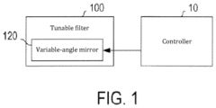
- FIG. 1 A block diagram for describing that a variable-angle mirror in a tunable filter is controlled by a controller.
- FIG. 2 A diagram for describing an optical configuration of the tunable filter.
- FIG. 3 An explanatory diagram relating to a beam diameter of light incident on a transmissive diffraction grating.
- FIG. 4 An explanatory diagram relating to the tunable filter, the tunable filter being provided with a bandwidth-compensating prism.
- FIG. 5 A graph for describing wavelength dependency of a bandwidth.
- FIG. 6 A table for describing the wavelength dependency of the bandwidth, which is reduced by the bandwidth-compensating prism.
- FIG. 7 A diagram for describing transmitted diffracted light and reflected diffracted light arising due to the transmissive diffraction grating.
- the tunable filter 100 of one or more embodiments illustrated in FIG. 1 is configured to be able to change a center wavelength ⁇ C of a passband and is controlled by a controller 10 .
- the tunable filter 100 and the controller 10 are built into an optical communication device.
- the tunable filter 100 is provided with a fiber collimator 110 serving as the optical input/output unit, a variable-angle mirror 120 , a transmissive diffraction grating 130 , and a fixed-angle mirror 140 .
- the tunable filter 100 can be further provided with beam-diameter-adjusting prisms 151 , 152 .
- the tunable filter 100 can be further provided with a half-wave plate 160 .
- the fiber collimator 110 is configured to optically couple input optical fibers 111 and output optical fibers 112 and input upstream light transmitted through the input optical fibers 111 into an internal space of the tunable filter 100 .
- the fiber collimator 110 collimates and outputs the input light from the input optical fibers 111 .
- the collimated input light output from the fiber collimator 110 is propagated to the variable-angle mirror 120 .
- this input light is filtered, and light of a defined wavelength band corresponding to an orientation of a reflective surface 121 of the variable-angle mirror 120 returns to a fiber-collimator 110 side.
- This light of the defined wavelength band is output as the output light to outside the tunable filter 100 through the output optical fibers 112 .
- the controller 10 adjusts the center wavelength ⁇ C of the passband of the tunable filter 100 by adjusting an angle of the reflective surface 121 of the variable-angle mirror 120 .
- the tunable filter 100 is configured as a narrowband band-pass filter of a variable passband.
- the variable-angle mirror 120 is constituted by a MEMS (microelectromechanical system) mirror and is configured so the angle of the reflective surface 121 thereof changes according to an applied voltage from the controller 10 .
- MEMS microelectromechanical system
- the input light reflected by the variable-angle reflective surface 121 of the variable-angle mirror 120 is propagated toward the transmissive diffraction grating 130 .
- the input light becomes incident on the transmissive diffraction grating 130 at an incidence angle ⁇ corresponding to the angle of the reflective surface 121 of the variable-angle mirror 120 .
- the incidence angle ⁇ is an angle of the incident light relative to a normal direction of the transmissive diffraction grating 130 .
- a beam diameter of the input light is adjusted by the beam-diameter-adjusting prisms 151 , 152 , which are optionally provided between the variable-angle mirror 120 and the transmissive diffraction grating 130 .
- the beam-diameter-adjusting prisms 151 , 152 adjust the beam diameter of the input light in an enlarging direction.
- the input light can be adjusted to spread in a direction perpendicular to a grating direction of the transmissive diffraction grating 130 .
- the input light from the variable-angle mirror 120 that becomes incident on the transmissive diffraction grating 130 is diffracted by the transmissive diffraction grating 130 to a diffraction angle ⁇ corresponding to the incidence angle ⁇ and a wavelength ⁇ and is propagated toward the fixed-angle mirror 140 as diffracted light.
- a relationship between the incidence angle ⁇ , which is an angle of the incident light relative to a normal line of the transmissive diffraction grating 130 ; the diffraction angle ⁇ , which is an angle of the diffracted light relative to the normal line of the transmissive diffraction grating 130 ; and the wavelength ⁇ of the incident light conforms to the following grating equation.
- N is an inverse of a diffraction-grating period d
- m is a diffraction order.
- the incidence angle ⁇ relative to the transmissive diffraction grating 130 is adjusted so first-positive-order transmitted diffracted light of the light of the defined wavelength band corresponding to the passband included in the input light becomes incident on a reflective surface 141 of the fixed-angle mirror 140 in a defined orientation.
- the defined orientation is an orientation wherein the incident light is reflected by the reflective surface 141 of the fixed-angle mirror 140 so the incident light is propagated down a regular path optically coupled to the output optical fibers 112 through the fiber collimator 110 .
- the fixed-angle mirror 140 is a mirror whose reflective surface 141 has a fixed orientation relative to the transmissive diffraction grating 130 . It differs from a MEMS mirror, whose reflective surface is variable.
- the fixed-angle mirror 140 is disposed so the reflective surface 141 reflects the diffracted light from the transmissive diffraction grating 130 .
- the light of the defined wavelength band corresponding to the passband is selectively reflected to be propagated down the regular path optically coupled to the output optical fibers 112 of the fiber collimator 110 .
- the light of the defined wavelength band is propagated down a return path, from the reflective surface 141 of the fixed-angle mirror 140 to the fiber collimator 110 via the transmissive diffraction grating 130 and the variable-angle mirror 120 , corresponding to an outward path from the fiber collimator 110 to the reflective surface 141 of the fixed-angle mirror 140 .
- This selectively outputs, among the diffracted light reflected by the fixed-angle mirror 140 , the light of the defined wavelength band to the outside from the output optical fibers 112 .
- the input light is filtered in this manner, and the light of the defined wavelength band corresponding to the angle of the reflective surface 121 of the variable-angle mirror 120 is output from the output optical fibers 112 .
- the half-wave plate 160 is optionally provided between the transmissive diffraction grating 130 and the fixed-angle mirror 140 .
- the half-wave plate 160 can be disposed between the transmissive diffraction grating 130 and the fixed-angle mirror 140 in a state of having an optical axis tilted 45 degrees relative to a grating axis of the transmissive diffraction grating 130 .
- this half-wave plate 160 Due to the presence of this half-wave plate 160 , a polarization state of the light that becomes incident on the transmissive diffraction grating 130 on the return path exhibits an orthogonal relationship to a polarization state of the light on the outward path. As such, even if the transmissive diffraction grating 130 has polarization dependency, polarization dependency of the output light output to outside the tunable filter 100 through the output optical fibers 112 can be removed.
- the half-wave plate 160 is disposed to act on the diffracted light on either the outward path or the return path.
- the outward path and the return path can be set so as to not overlap in a normal direction of the page in FIG. 2 .
- the half-wave plate 160 does not need to be disposed. However, the half-wave plate 160 may be disposed to compensate for polarization-dependent loss in the tunable filter 100 due to diffraction-efficiency polarization dependency remaining in the transmissive diffraction grating 130 .
- variable-angle mirror 120 for wavelength selection is disposed in a position, upstream from the transmissive diffraction grating 130 , where the optical beam diameter is small. Therefore, the variable-angle mirror 120 can be configured using a small MEMS mirror corresponding to the small optical beam diameter, and vibration and impact resistance of the tunable filter 100 can be increased.
- variable-angle mirror 120 can be configured using a small MEMS mirror having a high resonance frequency, and this enables the tunable filter 100 to be configured so as to be able to operate stably despite low-frequency vibrations and impacts.
- the transmissive diffraction grating 130 even if the beam diameter of the light incident on the transmissive diffraction grating 130 is increased to narrow the linewidth, there is no need to also increase a size of the MEMS mirror as in the conventional system.
- variable-angle mirror 120 is positioned upstream from the transmissive diffraction grating 130 .
- disposing the beam-diameter-adjusting prisms 151 , 152 between the variable-angle mirror 120 and the transmissive diffraction grating 130 enables the beam diameter of the light incident on the transmissive diffraction grating 130 to be increased without increasing a size of the variable-angle mirror 120 .
- a large-diameter beam on the transmissive diffraction grating 130 necessary for linewidth narrowing
- a small-diameter beam on the variable-angle mirror 120 necessary to use a small MEMS mirror having a high resonance frequency
- a tunable filter 100 can be realized that excels in vibration and impact resistance and has a narrow linewidth.
- the optical full width at half maximum of the tunable filter 100 that is, a bandwidth BW at ⁇ 3 dB—is calculated from the following formula.
- d is, as above, the diffraction-grating period of the transmissive diffraction grating 130 ; ⁇ is the wavelength of the light incident on the transmissive diffraction grating 130 ; ⁇ is the incidence angle of the light incident on the transmissive diffraction grating 130 ; a is a number of times of incidence on the diffraction grating; and W is the beam diameter (1/e 2 ) of the light incident on the transmissive diffraction grating 130 .
- the bandwidth BW is dependent on the beam diameter W—more specifically, it is proportional to an inverse of a projection beam width W/cos ⁇ that is an incidence-direction beam width of a projection of the light incident on the transmissive diffraction grating 130 onto the transmissive diffraction grating 130 .
- the projection beam width W/cos ⁇ is illustrated in FIG. 3 .
- the incidence angle ⁇ relative to the transmissive diffraction grating 130 must be adjusted to an angle corresponding to the center wavelength ⁇ C of the passband. That is, changing the center wavelength ⁇ C of the bandwidth changes the inverse of the beam width W/cos ⁇ and changes the bandwidth BW.
- the bandwidth BW has wavelength dependency. Therefore, to suppress the wavelength dependency of the bandwidth BW, the tunable filter 100 may be deformed (first variation).
- the tunable filter 100 of a first variation described below is a tunable filter wherein a majority of its configuration is identical to the tunable filter 100 of the main embodiments above. Therefore, in the following, differences between the tunable filter 100 of the first variation and the main embodiments above are selectively described, and other description is omitted as appropriate.
- the tunable filter 100 of the first variation is provided with a bandwidth-compensating prism 155 , for suppressing the wavelength dependency of the bandwidth BW, between the variable-angle mirror 120 and the transmissive diffraction grating 130 .
- the tunable filter 100 of the first variation may be provided with the bandwidth-compensating prism 155 separately from the above beam-diameter-adjusting prisms 151 , 152 or be provided with the bandwidth-compensating prism 155 as one or a plurality of the beam-diameter-adjusting prisms 151 , 152 .
- the bandwidth-compensating prism 155 is a right-triangle prism of an apex angle ⁇ .
- the bandwidth-compensating prism 155 is designed using simulation to have an optimal apex angle ⁇ and is disposed so an incidence angle ⁇ of the input light relative to the bandwidth-compensating prism 155 and the incidence angle ⁇ relative to the transmissive diffraction grating 130 , which is dependent on the incidence angle ⁇ , are optimal angles for a wavelength range ⁇ S to ⁇ L to be filtered.
- the wavelength range ⁇ S to ⁇ L to be filtered corresponds to a wavelength range from a shortest wavelength ⁇ S to a longest wavelength ⁇ L of the passband center wavelength ⁇ C that changes due to angle adjustment of the reflective surface 121 of the variable-angle mirror 120 .
- the simulation searches for an apex angle ⁇ and a disposition of the bandwidth-compensating prism 155 whereat, for cos ⁇ S /W S , an inverse of the projection beam width when the shortest wavelength ⁇ S is set as the passband center wavelength ⁇ C by angle adjustment of the reflective surface 121 of the variable-angle mirror 120 ; cos ⁇ M /W M , an inverse of the projection beam width when the middle wavelength ⁇ M is set as the passband center wavelength ⁇ C ; and cos ⁇ L /W L , an inverse of the projection beam width when the longest wavelength ⁇ L is set as the passband center wavelength ⁇ C , a sum of squares ⁇ of differences between these inverses at the wavelengths ⁇ S , ⁇ M , and ⁇ L is the smallest.
- the sum of squares ⁇ is represented by the following formula.
- the search can be realized by using the simulation to calculate the corresponding sum of squares ⁇ for all apex angles ⁇ and dispositions that can be realized. According to a simple simulation, the search can be performed upon fixing design parameters other than the apex angle ⁇ and disposition of the bandwidth-compensating prism 155 and the disposition of the fixed-angle mirror 140 in the tunable filter 100 .
- the disposition of the fixed-angle mirror 140 can be determined so the fixed-angle mirror 140 is disposed in a position wherethrough a first-order transmitted diffracted light of the wavelength range ⁇ S to ⁇ L passes.
- the bandwidth-compensating prism 155 of the apex angle ⁇ searched for in this manner that minimizes the sum of squares ⁇ , in the corresponding orientation, the differences between the inverses of the projection beam width W/cos ⁇ at the wavelengths ⁇ S , ⁇ M , and ⁇ L are suppressed. As illustrated by the bold solid line in FIG. 5 , this can suppress fluctuation of the bandwidth BW relative to the passband center wavelength ⁇ C .
- the graph illustrated in FIG. 5 uses the bold solid line to illustrate changes in the bandwidth BW relative to the passband center wavelength ⁇ C in the tunable filter 100 having the appropriately designed and disposed bandwidth-compensating prism 155 .
- the dotted line in FIG. 5 illustrates changes in the beam diameter W relative to the wavelength ⁇ C
- the dot-dash line therein illustrates changes in the incidence angle ⁇ (specifically, cos ⁇ ) relative to the wavelength ⁇ C .
- the table in FIG. 6 shows, in the lowest row, examples of the bandwidth BW (GHz) at each wavelength ⁇ C when the passband center wavelength ⁇ C is set to 1,527 nm, 1,549 nm, and 1,570 nm, the bandwidths BW (GHz) being from when the bandwidth-compensating prism 155 is appropriately designed and disposed.
- ⁇ indicates the incidence angle relative to the bandwidth-compensating prism 155 (see FIG. 4 ).
- the table also shows, in the middle row, examples of the bandwidth BW (GHz) when the bandwidth-compensating prism 155 is not provided, as comparative examples.
- a tunable filter 100 wherein the wavelength dependency of the bandwidth BW is suppressed can be configured by using an appropriately designed bandwidth-compensating prism 155 .
- the tunable filter 100 of a second variation described below is a tunable filter wherein a majority of its configuration is identical to the tunable filter 100 of the main embodiments above. Therefore, in the following, differences between the tunable filter 100 of the second variation and the main embodiments above are selectively described, and other description is omitted as appropriate.
- the tunable filter 100 of the second variation is designed to suppress reflected diffracted light arising at the transmissive diffraction grating 130 from going back up the propagation path of the input light to return upstream from the input optical fibers 111 .
- the tunable filter 100 is, for example, used after an optical amplifier. In this situation, the tunable filter 100 is useful in removing optical noise added by the optical amplifier—that is, ASE noise—to improve an optical S/N ratio.
- optical noise added by the optical amplifier that is, ASE noise
- transmitted diffracted light and reflected diffracted light are generated as the diffracted light corresponding to the incident light. That among these, the first-positive-order transmitted diffracted light is used as the output of the tunable filter 100 is as described in the main embodiments above.
- the reflected diffracted light may be reflected at the same angle as the incident light, and this reflected diffracted light becomes a factor in degrading the return loss of the tunable filter 100 .
- the incidence angle ⁇ is set to about 45 degrees.
- the reflected diffracted light is propagated so as to go back up the propagation path of the incident light, which is from the fiber collimator 110 to incidence on the transmissive diffraction grating 130 via the variable-angle mirror 120 , and returns upstream through the input optical fibers 111 .
- the incidence angle ⁇ is established according to the passband center wavelength ⁇ C and is a function ⁇ ( ⁇ ) of the wavelength ⁇ Therefore, in the second variation, the disposition of the optical system—including the positions and orientations of the variable-angle mirror 120 , the transmissive diffraction grating 130 , and the fixed-angle mirror 140 —is designed and the tunable filter 100 is configured so the relational expression 2 ⁇ sin ⁇ ( ⁇ ) ⁇ Nm ⁇ is satisfied for the entire wavelength range ⁇ S to ⁇ L (that is, ⁇ S ⁇ L ) of the input light to be filtered.
- the controller 10 can cause the tunable filter 100 to function as a narrow-linewidth filter that varies in the wavelength range ⁇ S to ⁇ L and has favorable return loss by adjusting the angle of the reflective surface 121 of the variable-angle mirror 120 in the tunable filter 100 so the relational expression 2 ⁇ sin ⁇ ( ⁇ ) ⁇ Nm ⁇ is satisfied for the wavelength range ⁇ S to ⁇ L .
- Embodiments of the present disclosure including variations, are described above.
- the present disclosure is not limited to the above embodiments and can adopt various aspects.
- a prism for adjusting the beam diameter may be provided between the transmissive diffraction grating 130 and the fixed-angle mirror 140 .
- the technical idea of the second variation may be applied to the first variation.
- a function had by one component in the above embodiments may be provided dispersed among a plurality of components.
- a function had by a plurality of components may be integrated into one component.
- a portion of the configuration of the above embodiments may be omitted.
- At least one portion of the configuration of the above embodiments may be added to another configuration of the above embodiments or be substituted.
- the embodiments of the present disclosure include all aspects included in the technical idea defined from the wording given in the scope of patent claims.
- 10 . . . controller 100 . . . tunable filter; 110 . . . fiber collimator; 111 . . . input optical fibers; 112 . . . output optical fibers; 120 . . . variable-angle mirror; 121 . . . reflective surface; 130 . . . transmissive diffraction grating; 140 . . . fixed-angle mirror; 141 . . . reflective surface; 151 , 152 . . . beam-diameter-adjusting prism; 155 . . . bandwidth-compensating prism; 160 . . . half-wave plate.
Landscapes
- Physics & Mathematics (AREA)
- General Physics & Mathematics (AREA)
- Optics & Photonics (AREA)
- Spectroscopy & Molecular Physics (AREA)
- Mechanical Light Control Or Optical Switches (AREA)
- Diffracting Gratings Or Hologram Optical Elements (AREA)
Abstract
Description
- [Patent Literature 1] US 2008/0085119 A1
sin α+sin β=Nmλ
Claims (10)
2 sin α≠Nmλ,
Applications Claiming Priority (2)
| Application Number | Priority Date | Filing Date | Title |
|---|---|---|---|
| JP2020166049A JP6853603B1 (en) | 2020-09-30 | 2020-09-30 | Tunable filter |
| JP2020-166049 | 2020-09-30 |
Publications (2)
| Publication Number | Publication Date |
|---|---|
| US20220099991A1 US20220099991A1 (en) | 2022-03-31 |
| US11927770B2 true US11927770B2 (en) | 2024-03-12 |
Family
ID=75158379
Family Applications (1)
| Application Number | Title | Priority Date | Filing Date |
|---|---|---|---|
| US17/147,020 Active 2042-05-10 US11927770B2 (en) | 2020-09-30 | 2021-01-12 | Variable wavelength filter |
Country Status (2)
| Country | Link |
|---|---|
| US (1) | US11927770B2 (en) |
| JP (1) | JP6853603B1 (en) |
Families Citing this family (1)
| Publication number | Priority date | Publication date | Assignee | Title |
|---|---|---|---|---|
| JP7719556B1 (en) * | 2024-02-28 | 2025-08-06 | santec Holdings株式会社 | Tunable wavelength filter |
Citations (14)
| Publication number | Priority date | Publication date | Assignee | Title |
|---|---|---|---|---|
| US20080085119A1 (en) | 2006-10-04 | 2008-04-10 | Dicon Fiberoptics, Inc. | Compact High-Resolution Tunable Optical Filter Using Optical Diffraction Element and a Mirror |
| US7382809B2 (en) * | 2005-02-25 | 2008-06-03 | Santec Corporation | Tunable fiber laser light source |
| US7408639B1 (en) * | 2004-04-23 | 2008-08-05 | Nistica, Inc. | Tunable optical routing systems |
| JP2008203508A (en) | 2007-02-20 | 2008-09-04 | Sun Tec Kk | Optical variable filter |
| US20080212338A1 (en) * | 2001-11-07 | 2008-09-04 | Sayuri Kohara | Prism sheet, a back-light unit using said prism sheet, and a transmission type liquid crystal display device |
| US20090303562A1 (en) * | 2008-06-09 | 2009-12-10 | Cardinalpoint Optics Inc. | High-resolution spectrally adjustable filter |
| JP2010520491A (en) | 2007-03-02 | 2010-06-10 | シーリアル テクノロジーズ ソシエテ アノニム | Apparatus for minimizing diffraction-related dispersion in optical modulators. |
| US20120224181A1 (en) | 2012-05-08 | 2012-09-06 | Ms. Hongxia Lu | Wide-Band/High-Resolution Tunable Spectral Filter |
| CN104931138A (en) | 2015-07-13 | 2015-09-23 | 中北大学 | Method of using prism to increase AOTF spectrum imaging quality and apparatus thereof |
| US20160165324A1 (en) * | 2013-08-22 | 2016-06-09 | Huawei Technologies Co., Ltd. | Wavelength selective switch |
| WO2018101281A1 (en) | 2016-11-29 | 2018-06-07 | スペクトラ・クエスト・ラボ株式会社 | Optical device |
| JP2018155933A (en) | 2017-03-17 | 2018-10-04 | サンテック株式会社 | Integrated optical device |
| CN108828766A (en) | 2018-06-14 | 2018-11-16 | 湖北捷讯光电有限公司 | A kind of narrowband tunable optical filter |
| CN209928136U (en) | 2019-06-10 | 2020-01-10 | 福州高意通讯有限公司 | Tunable optical fiber filter with variable broadband and wavelength |
Family Cites Families (2)
| Publication number | Priority date | Publication date | Assignee | Title |
|---|---|---|---|---|
| JP2008151830A (en) * | 2006-12-14 | 2008-07-03 | Sun Tec Kk | Tunable filter |
| JP6688442B1 (en) * | 2019-01-31 | 2020-04-28 | サンテック株式会社 | Tunable filter and optical system |
-
2020
- 2020-09-30 JP JP2020166049A patent/JP6853603B1/en active Active
-
2021
- 2021-01-12 US US17/147,020 patent/US11927770B2/en active Active
Patent Citations (14)
| Publication number | Priority date | Publication date | Assignee | Title |
|---|---|---|---|---|
| US20080212338A1 (en) * | 2001-11-07 | 2008-09-04 | Sayuri Kohara | Prism sheet, a back-light unit using said prism sheet, and a transmission type liquid crystal display device |
| US7408639B1 (en) * | 2004-04-23 | 2008-08-05 | Nistica, Inc. | Tunable optical routing systems |
| US7382809B2 (en) * | 2005-02-25 | 2008-06-03 | Santec Corporation | Tunable fiber laser light source |
| US20080085119A1 (en) | 2006-10-04 | 2008-04-10 | Dicon Fiberoptics, Inc. | Compact High-Resolution Tunable Optical Filter Using Optical Diffraction Element and a Mirror |
| JP2008203508A (en) | 2007-02-20 | 2008-09-04 | Sun Tec Kk | Optical variable filter |
| JP2010520491A (en) | 2007-03-02 | 2010-06-10 | シーリアル テクノロジーズ ソシエテ アノニム | Apparatus for minimizing diffraction-related dispersion in optical modulators. |
| US20090303562A1 (en) * | 2008-06-09 | 2009-12-10 | Cardinalpoint Optics Inc. | High-resolution spectrally adjustable filter |
| US20120224181A1 (en) | 2012-05-08 | 2012-09-06 | Ms. Hongxia Lu | Wide-Band/High-Resolution Tunable Spectral Filter |
| US20160165324A1 (en) * | 2013-08-22 | 2016-06-09 | Huawei Technologies Co., Ltd. | Wavelength selective switch |
| CN104931138A (en) | 2015-07-13 | 2015-09-23 | 中北大学 | Method of using prism to increase AOTF spectrum imaging quality and apparatus thereof |
| WO2018101281A1 (en) | 2016-11-29 | 2018-06-07 | スペクトラ・クエスト・ラボ株式会社 | Optical device |
| JP2018155933A (en) | 2017-03-17 | 2018-10-04 | サンテック株式会社 | Integrated optical device |
| CN108828766A (en) | 2018-06-14 | 2018-11-16 | 湖北捷讯光电有限公司 | A kind of narrowband tunable optical filter |
| CN209928136U (en) | 2019-06-10 | 2020-01-10 | 福州高意通讯有限公司 | Tunable optical fiber filter with variable broadband and wavelength |
Non-Patent Citations (1)
| Title |
|---|
| Notification of Reasons for Refusal issued in Japanese Patent Application No. 2020-166049, dated Nov. 10, 2020 (10 pages). |
Also Published As
| Publication number | Publication date |
|---|---|
| JP2022057669A (en) | 2022-04-11 |
| JP6853603B1 (en) | 2021-03-31 |
| US20220099991A1 (en) | 2022-03-31 |
Similar Documents
| Publication | Publication Date | Title |
|---|---|---|
| USRE43965E1 (en) | Compensating for chromatic dispersion in optical fibers | |
| US6407855B1 (en) | Multiple wavelength optical sources | |
| US5740292A (en) | Mode coupling optical waveguide grating | |
| USRE43226E1 (en) | Optical multiplexing device | |
| US5311606A (en) | Optical filter and optical amplifier employing said optical filters | |
| EP1628148B1 (en) | Polarization insensitive optical fibre | |
| JP6688442B1 (en) | Tunable filter and optical system | |
| US6967976B2 (en) | Laser with reflective etalon tuning element | |
| JP2017204530A (en) | External cavity semiconductor laser device | |
| JP2007163780A (en) | Multi-wavelength spectrometer | |
| EP2905851B1 (en) | Optical lasing device and method for generating a lasing mode in such device | |
| JP2000174368A (en) | Multiple wavelength laser source | |
| US11927770B2 (en) | Variable wavelength filter | |
| US7230761B2 (en) | High-dispersion grisms | |
| US20120224181A1 (en) | Wide-Band/High-Resolution Tunable Spectral Filter | |
| US12457053B2 (en) | Optical transmission system | |
| US6959023B1 (en) | Laser with reflective etalon tuning element | |
| US20020135879A1 (en) | Super high resolution optical resonator | |
| JP2004511914A (en) | Tunable single mode laser device | |
| JP7809389B2 (en) | Tunable wavelength filter | |
| US20060056465A1 (en) | Laser with reflective etalon tuning element | |
| US6856443B2 (en) | Method for using length dispersion in an etalon to approximate target resonant frequencies | |
| KR20050019879A (en) | Compensating for chromatic dispersion in optical fibers |
Legal Events
| Date | Code | Title | Description |
|---|---|---|---|
| FEPP | Fee payment procedure |
Free format text: ENTITY STATUS SET TO UNDISCOUNTED (ORIGINAL EVENT CODE: BIG.); ENTITY STATUS OF PATENT OWNER: SMALL ENTITY |
|
| AS | Assignment |
Owner name: SANTEC CORPORATION, JAPAN Free format text: ASSIGNMENT OF ASSIGNORS INTEREST;ASSIGNOR:SAKURAI, YASUKI;REEL/FRAME:054917/0852 Effective date: 20201215 |
|
| FEPP | Fee payment procedure |
Free format text: ENTITY STATUS SET TO SMALL (ORIGINAL EVENT CODE: SMAL); ENTITY STATUS OF PATENT OWNER: SMALL ENTITY |
|
| STPP | Information on status: patent application and granting procedure in general |
Free format text: DOCKETED NEW CASE - READY FOR EXAMINATION |
|
| STPP | Information on status: patent application and granting procedure in general |
Free format text: NON FINAL ACTION MAILED |
|
| STPP | Information on status: patent application and granting procedure in general |
Free format text: RESPONSE TO NON-FINAL OFFICE ACTION ENTERED AND FORWARDED TO EXAMINER |
|
| STPP | Information on status: patent application and granting procedure in general |
Free format text: NOTICE OF ALLOWANCE MAILED -- APPLICATION RECEIVED IN OFFICE OF PUBLICATIONS |
|
| STPP | Information on status: patent application and granting procedure in general |
Free format text: PUBLICATIONS -- ISSUE FEE PAYMENT VERIFIED |
|
| STCF | Information on status: patent grant |
Free format text: PATENTED CASE |
|
| AS | Assignment |
Owner name: SANTEC HOLDINGS CORPORATION, JAPAN Free format text: CHANGE OF NAME;ASSIGNOR:SANTEC CORPORATION;REEL/FRAME:066530/0591 Effective date: 20230403 |