US11925824B2 - Method and apparatus for launching and recovering a remote inspection device from a volatile liquid storage tank - Google Patents
Method and apparatus for launching and recovering a remote inspection device from a volatile liquid storage tank Download PDFInfo
- Publication number
- US11925824B2 US11925824B2 US16/539,697 US201916539697A US11925824B2 US 11925824 B2 US11925824 B2 US 11925824B2 US 201916539697 A US201916539697 A US 201916539697A US 11925824 B2 US11925824 B2 US 11925824B2
- Authority
- US
- United States
- Prior art keywords
- inspection device
- storage vessel
- internal volume
- chamber body
- closure
- Prior art date
- Legal status (The legal status is an assumption and is not a legal conclusion. Google has not performed a legal analysis and makes no representation as to the accuracy of the status listed.)
- Active, expires
Links
- 238000007689 inspection Methods 0.000 title claims abstract description 138
- 239000007788 liquid Substances 0.000 title abstract description 90
- 238000000034 method Methods 0.000 title abstract description 32
- 238000002347 injection Methods 0.000 claims abstract description 26
- 239000007924 injection Substances 0.000 claims abstract description 26
- 239000011261 inert gas Substances 0.000 claims abstract description 24
- 239000007789 gas Substances 0.000 claims description 22
- 230000008878 coupling Effects 0.000 claims description 12
- 238000010168 coupling process Methods 0.000 claims description 12
- 238000005859 coupling reaction Methods 0.000 claims description 12
- 239000012530 fluid Substances 0.000 claims description 12
- 238000004140 cleaning Methods 0.000 claims description 10
- 230000000712 assembly Effects 0.000 claims description 8
- 238000000429 assembly Methods 0.000 claims description 8
- 230000033001 locomotion Effects 0.000 claims description 7
- 239000007921 spray Substances 0.000 claims description 6
- 238000007789 sealing Methods 0.000 claims description 2
- 238000011084 recovery Methods 0.000 abstract description 50
- 239000006260 foam Substances 0.000 abstract description 41
- 230000001629 suppression Effects 0.000 abstract description 22
- 231100001261 hazardous Toxicity 0.000 abstract description 8
- 239000004215 Carbon black (E152) Substances 0.000 description 11
- 229930195733 hydrocarbon Natural products 0.000 description 11
- 150000002430 hydrocarbons Chemical class 0.000 description 11
- 238000012360 testing method Methods 0.000 description 8
- 239000000463 material Substances 0.000 description 7
- RTAQQCXQSZGOHL-UHFFFAOYSA-N Titanium Chemical compound [Ti] RTAQQCXQSZGOHL-UHFFFAOYSA-N 0.000 description 6
- 229910052782 aluminium Inorganic materials 0.000 description 6
- XAGFODPZIPBFFR-UHFFFAOYSA-N aluminium Chemical compound [Al] XAGFODPZIPBFFR-UHFFFAOYSA-N 0.000 description 6
- 229910001092 metal group alloy Inorganic materials 0.000 description 6
- 239000007769 metal material Substances 0.000 description 6
- 239000010936 titanium Substances 0.000 description 6
- 229910052719 titanium Inorganic materials 0.000 description 6
- 230000007246 mechanism Effects 0.000 description 5
- 239000000047 product Substances 0.000 description 5
- XKRFYHLGVUSROY-UHFFFAOYSA-N Argon Chemical compound [Ar] XKRFYHLGVUSROY-UHFFFAOYSA-N 0.000 description 4
- IJGRMHOSHXDMSA-UHFFFAOYSA-N Atomic nitrogen Chemical compound N#N IJGRMHOSHXDMSA-UHFFFAOYSA-N 0.000 description 4
- 238000010586 diagram Methods 0.000 description 4
- 230000008569 process Effects 0.000 description 4
- 239000010935 stainless steel Substances 0.000 description 4
- 229910001220 stainless steel Inorganic materials 0.000 description 4
- LFQSCWFLJHTTHZ-UHFFFAOYSA-N Ethanol Chemical compound CCO LFQSCWFLJHTTHZ-UHFFFAOYSA-N 0.000 description 3
- 239000010779 crude oil Substances 0.000 description 3
- 229920006169 Perfluoroelastomer Polymers 0.000 description 2
- 239000004696 Poly ether ether ketone Substances 0.000 description 2
- 230000004913 activation Effects 0.000 description 2
- 229910052786 argon Inorganic materials 0.000 description 2
- QVGXLLKOCUKJST-UHFFFAOYSA-N atomic oxygen Chemical compound [O] QVGXLLKOCUKJST-UHFFFAOYSA-N 0.000 description 2
- JUPQTSLXMOCDHR-UHFFFAOYSA-N benzene-1,4-diol;bis(4-fluorophenyl)methanone Chemical compound OC1=CC=C(O)C=C1.C1=CC(F)=CC=C1C(=O)C1=CC=C(F)C=C1 JUPQTSLXMOCDHR-UHFFFAOYSA-N 0.000 description 2
- 238000007667 floating Methods 0.000 description 2
- 239000003502 gasoline Substances 0.000 description 2
- 229910052757 nitrogen Inorganic materials 0.000 description 2
- 239000001301 oxygen Substances 0.000 description 2
- 229910052760 oxygen Inorganic materials 0.000 description 2
- 229920002530 polyetherether ketone Polymers 0.000 description 2
- 239000004810 polytetrafluoroethylene Substances 0.000 description 2
- 229920001343 polytetrafluoroethylene Polymers 0.000 description 2
- 102000004169 proteins and genes Human genes 0.000 description 2
- 108090000623 proteins and genes Proteins 0.000 description 2
- 239000003566 sealing material Substances 0.000 description 2
- 230000035939 shock Effects 0.000 description 2
- 238000004804 winding Methods 0.000 description 2
- 229910000975 Carbon steel Inorganic materials 0.000 description 1
- 229910000990 Ni alloy Inorganic materials 0.000 description 1
- 229910000831 Steel Inorganic materials 0.000 description 1
- 239000002253 acid Substances 0.000 description 1
- 150000007513 acids Chemical class 0.000 description 1
- 239000000853 adhesive Substances 0.000 description 1
- 230000001070 adhesive effect Effects 0.000 description 1
- 230000004075 alteration Effects 0.000 description 1
- 239000010962 carbon steel Substances 0.000 description 1
- 238000004210 cathodic protection Methods 0.000 description 1
- 239000003795 chemical substances by application Substances 0.000 description 1
- 238000011109 contamination Methods 0.000 description 1
- 238000005260 corrosion Methods 0.000 description 1
- 230000007797 corrosion Effects 0.000 description 1
- 238000006073 displacement reaction Methods 0.000 description 1
- 239000002360 explosive Substances 0.000 description 1
- 239000000295 fuel oil Substances 0.000 description 1
- 229910000856 hastalloy Inorganic materials 0.000 description 1
- 230000002779 inactivation Effects 0.000 description 1
- 239000003350 kerosene Substances 0.000 description 1
- 239000012263 liquid product Substances 0.000 description 1
- 229910052751 metal Inorganic materials 0.000 description 1
- 239000002184 metal Substances 0.000 description 1
- 230000009972 noncorrosive effect Effects 0.000 description 1
- 230000003287 optical effect Effects 0.000 description 1
- 238000012354 overpressurization Methods 0.000 description 1
- 230000000737 periodic effect Effects 0.000 description 1
- 239000003208 petroleum Substances 0.000 description 1
- 230000003449 preventive effect Effects 0.000 description 1
- 238000005096 rolling process Methods 0.000 description 1
- 150000003839 salts Chemical class 0.000 description 1
- 239000010959 steel Substances 0.000 description 1
- 238000006467 substitution reaction Methods 0.000 description 1
- 238000005406 washing Methods 0.000 description 1
Images


Classifications
-
- A—HUMAN NECESSITIES
- A62—LIFE-SAVING; FIRE-FIGHTING
- A62C—FIRE-FIGHTING
- A62C3/00—Fire prevention, containment or extinguishing specially adapted for particular objects or places
- A62C3/06—Fire prevention, containment or extinguishing specially adapted for particular objects or places of highly inflammable material, e.g. light metals, petroleum products
- A62C3/065—Fire prevention, containment or extinguishing specially adapted for particular objects or places of highly inflammable material, e.g. light metals, petroleum products for containers filled with inflammable liquids
-
- A—HUMAN NECESSITIES
- A62—LIFE-SAVING; FIRE-FIGHTING
- A62C—FIRE-FIGHTING
- A62C99/00—Subject matter not provided for in other groups of this subclass
- A62C99/0009—Methods of extinguishing or preventing the spread of fire by cooling down or suffocating the flames
- A62C99/0036—Methods of extinguishing or preventing the spread of fire by cooling down or suffocating the flames using foam
-
- B—PERFORMING OPERATIONS; TRANSPORTING
- B08—CLEANING
- B08B—CLEANING IN GENERAL; PREVENTION OF FOULING IN GENERAL
- B08B3/00—Cleaning by methods involving the use or presence of liquid or steam
- B08B3/02—Cleaning by the force of jets or sprays
-
- B—PERFORMING OPERATIONS; TRANSPORTING
- B08—CLEANING
- B08B—CLEANING IN GENERAL; PREVENTION OF FOULING IN GENERAL
- B08B9/00—Cleaning hollow articles by methods or apparatus specially adapted thereto
- B08B9/02—Cleaning pipes or tubes or systems of pipes or tubes
- B08B9/027—Cleaning the internal surfaces; Removal of blockages
-
- B—PERFORMING OPERATIONS; TRANSPORTING
- B63—SHIPS OR OTHER WATERBORNE VESSELS; RELATED EQUIPMENT
- B63C—LAUNCHING, HAULING-OUT, OR DRY-DOCKING OF VESSELS; LIFE-SAVING IN WATER; EQUIPMENT FOR DWELLING OR WORKING UNDER WATER; MEANS FOR SALVAGING OR SEARCHING FOR UNDERWATER OBJECTS
- B63C3/00—Launching or hauling-out by landborne slipways; Slipways
- B63C3/06—Launching or hauling-out by landborne slipways; Slipways by vertical movement of vessel, i.e. by crane
-
- B—PERFORMING OPERATIONS; TRANSPORTING
- B65—CONVEYING; PACKING; STORING; HANDLING THIN OR FILAMENTARY MATERIAL
- B65D—CONTAINERS FOR STORAGE OR TRANSPORT OF ARTICLES OR MATERIALS, e.g. BAGS, BARRELS, BOTTLES, BOXES, CANS, CARTONS, CRATES, DRUMS, JARS, TANKS, HOPPERS, FORWARDING CONTAINERS; ACCESSORIES, CLOSURES, OR FITTINGS THEREFOR; PACKAGING ELEMENTS; PACKAGES
- B65D90/00—Component parts, details or accessories for large containers
- B65D90/22—Safety features
- B65D90/38—Means for reducing the vapour space or for reducing the formation of vapour within containers
- B65D90/44—Means for reducing the vapour space or for reducing the formation of vapour within containers by use of inert gas for filling space above liquid or between contents
-
- B—PERFORMING OPERATIONS; TRANSPORTING
- B65—CONVEYING; PACKING; STORING; HANDLING THIN OR FILAMENTARY MATERIAL
- B65D—CONTAINERS FOR STORAGE OR TRANSPORT OF ARTICLES OR MATERIALS, e.g. BAGS, BARRELS, BOTTLES, BOXES, CANS, CARTONS, CRATES, DRUMS, JARS, TANKS, HOPPERS, FORWARDING CONTAINERS; ACCESSORIES, CLOSURES, OR FITTINGS THEREFOR; PACKAGING ELEMENTS; PACKAGES
- B65D90/00—Component parts, details or accessories for large containers
- B65D90/48—Arrangements of indicating or measuring devices
-
- B—PERFORMING OPERATIONS; TRANSPORTING
- B66—HOISTING; LIFTING; HAULING
- B66F—HOISTING, LIFTING, HAULING OR PUSHING, NOT OTHERWISE PROVIDED FOR, e.g. DEVICES WHICH APPLY A LIFTING OR PUSHING FORCE DIRECTLY TO THE SURFACE OF A LOAD
- B66F11/00—Lifting devices specially adapted for particular uses not otherwise provided for
- B66F11/04—Lifting devices specially adapted for particular uses not otherwise provided for for movable platforms or cabins, e.g. on vehicles, permitting workmen to place themselves in any desired position for carrying out required operations
-
- B—PERFORMING OPERATIONS; TRANSPORTING
- B66—HOISTING; LIFTING; HAULING
- B66F—HOISTING, LIFTING, HAULING OR PUSHING, NOT OTHERWISE PROVIDED FOR, e.g. DEVICES WHICH APPLY A LIFTING OR PUSHING FORCE DIRECTLY TO THE SURFACE OF A LOAD
- B66F19/00—Hoisting, lifting, hauling or pushing, not otherwise provided for
-
- G—PHYSICS
- G01—MEASURING; TESTING
- G01N—INVESTIGATING OR ANALYSING MATERIALS BY DETERMINING THEIR CHEMICAL OR PHYSICAL PROPERTIES
- G01N35/00—Automatic analysis not limited to methods or materials provided for in any single one of groups G01N1/00 - G01N33/00; Handling materials therefor
- G01N35/0099—Automatic analysis not limited to methods or materials provided for in any single one of groups G01N1/00 - G01N33/00; Handling materials therefor comprising robots or similar manipulators
-
- B—PERFORMING OPERATIONS; TRANSPORTING
- B25—HAND TOOLS; PORTABLE POWER-DRIVEN TOOLS; MANIPULATORS
- B25H—WORKSHOP EQUIPMENT, e.g. FOR MARKING-OUT WORK; STORAGE MEANS FOR WORKSHOPS
- B25H1/00—Work benches; Portable stands or supports for positioning portable tools or work to be operated on thereby
- B25H1/14—Work benches; Portable stands or supports for positioning portable tools or work to be operated on thereby with provision for adjusting the bench top
-
- B—PERFORMING OPERATIONS; TRANSPORTING
- B25—HAND TOOLS; PORTABLE POWER-DRIVEN TOOLS; MANIPULATORS
- B25H—WORKSHOP EQUIPMENT, e.g. FOR MARKING-OUT WORK; STORAGE MEANS FOR WORKSHOPS
- B25H3/00—Storage means or arrangements for workshops facilitating access to, or handling of, work tools or instruments
-
- B—PERFORMING OPERATIONS; TRANSPORTING
- B65—CONVEYING; PACKING; STORING; HANDLING THIN OR FILAMENTARY MATERIAL
- B65H—HANDLING THIN OR FILAMENTARY MATERIAL, e.g. SHEETS, WEBS, CABLES
- B65H2403/00—Power transmission; Driving means
- B65H2403/50—Driving mechanisms
- B65H2403/54—Driving mechanisms other
- B65H2403/544—Driving mechanisms other involving rolling up - unrolling of transmission element, e.g. winch
-
- B—PERFORMING OPERATIONS; TRANSPORTING
- B65—CONVEYING; PACKING; STORING; HANDLING THIN OR FILAMENTARY MATERIAL
- B65H—HANDLING THIN OR FILAMENTARY MATERIAL, e.g. SHEETS, WEBS, CABLES
- B65H75/00—Storing webs, tapes, or filamentary material, e.g. on reels
- B65H75/02—Cores, formers, supports, or holders for coiled, wound, or folded material, e.g. reels, spindles, bobbins, cop tubes, cans, mandrels or chucks
- B65H75/34—Cores, formers, supports, or holders for coiled, wound, or folded material, e.g. reels, spindles, bobbins, cop tubes, cans, mandrels or chucks specially adapted or mounted for storing and repeatedly paying-out and re-storing lengths of material provided for particular purposes, e.g. anchored hoses, power cables
- B65H75/36—Cores, formers, supports, or holders for coiled, wound, or folded material, e.g. reels, spindles, bobbins, cop tubes, cans, mandrels or chucks specially adapted or mounted for storing and repeatedly paying-out and re-storing lengths of material provided for particular purposes, e.g. anchored hoses, power cables without essentially involving the use of a core or former internal to a stored package of material, e.g. with stored material housed within casing or container, or intermittently engaging a plurality of supports as in sinuous or serpentine fashion
- B65H75/368—Cores, formers, supports, or holders for coiled, wound, or folded material, e.g. reels, spindles, bobbins, cop tubes, cans, mandrels or chucks specially adapted or mounted for storing and repeatedly paying-out and re-storing lengths of material provided for particular purposes, e.g. anchored hoses, power cables without essentially involving the use of a core or former internal to a stored package of material, e.g. with stored material housed within casing or container, or intermittently engaging a plurality of supports as in sinuous or serpentine fashion with pulleys
-
- E—FIXED CONSTRUCTIONS
- E04—BUILDING
- E04G—SCAFFOLDING; FORMS; SHUTTERING; BUILDING IMPLEMENTS OR AIDS, OR THEIR USE; HANDLING BUILDING MATERIALS ON THE SITE; REPAIRING, BREAKING-UP OR OTHER WORK ON EXISTING BUILDINGS
- E04G3/00—Scaffolds essentially supported by building constructions, e.g. adjustable in height
- E04G3/28—Mobile scaffolds; Scaffolds with mobile platforms
- E04G3/30—Mobile scaffolds; Scaffolds with mobile platforms suspended by flexible supporting elements, e.g. cables
-
- G—PHYSICS
- G01—MEASURING; TESTING
- G01N—INVESTIGATING OR ANALYSING MATERIALS BY DETERMINING THEIR CHEMICAL OR PHYSICAL PROPERTIES
- G01N21/00—Investigating or analysing materials by the use of optical means, i.e. using sub-millimetre waves, infrared, visible or ultraviolet light
- G01N21/84—Systems specially adapted for particular applications
- G01N21/88—Investigating the presence of flaws or contamination
- G01N21/95—Investigating the presence of flaws or contamination characterised by the material or shape of the object to be examined
- G01N21/954—Inspecting the inner surface of hollow bodies, e.g. bores
- G01N2021/9548—Scanning the interior of a cylinder
-
- G—PHYSICS
- G01—MEASURING; TESTING
- G01N—INVESTIGATING OR ANALYSING MATERIALS BY DETERMINING THEIR CHEMICAL OR PHYSICAL PROPERTIES
- G01N21/00—Investigating or analysing materials by the use of optical means, i.e. using sub-millimetre waves, infrared, visible or ultraviolet light
- G01N21/84—Systems specially adapted for particular applications
- G01N21/88—Investigating the presence of flaws or contamination
- G01N21/90—Investigating the presence of flaws or contamination in a container or its contents
- G01N21/909—Investigating the presence of flaws or contamination in a container or its contents in opaque containers or opaque container parts, e.g. cans, tins, caps, labels
-
- G—PHYSICS
- G01—MEASURING; TESTING
- G01N—INVESTIGATING OR ANALYSING MATERIALS BY DETERMINING THEIR CHEMICAL OR PHYSICAL PROPERTIES
- G01N2201/00—Features of devices classified in G01N21/00
- G01N2201/02—Mechanical
- G01N2201/021—Special mounting in general
- G01N2201/0218—Submersible, submarine
-
- G—PHYSICS
- G01—MEASURING; TESTING
- G01N—INVESTIGATING OR ANALYSING MATERIALS BY DETERMINING THEIR CHEMICAL OR PHYSICAL PROPERTIES
- G01N2291/00—Indexing codes associated with group G01N29/00
- G01N2291/02—Indexing codes associated with the analysed material
- G01N2291/023—Solids
- G01N2291/0234—Metals, e.g. steel
-
- G—PHYSICS
- G01—MEASURING; TESTING
- G01N—INVESTIGATING OR ANALYSING MATERIALS BY DETERMINING THEIR CHEMICAL OR PHYSICAL PROPERTIES
- G01N2291/00—Indexing codes associated with group G01N29/00
- G01N2291/02—Indexing codes associated with the analysed material
- G01N2291/025—Change of phase or condition
- G01N2291/0258—Structural degradation, e.g. fatigue of composites, ageing of oils
-
- G—PHYSICS
- G01—MEASURING; TESTING
- G01N—INVESTIGATING OR ANALYSING MATERIALS BY DETERMINING THEIR CHEMICAL OR PHYSICAL PROPERTIES
- G01N2291/00—Indexing codes associated with group G01N29/00
- G01N2291/26—Scanned objects
- G01N2291/263—Surfaces
- G01N2291/2636—Surfaces cylindrical from inside
-
- G—PHYSICS
- G01—MEASURING; TESTING
- G01N—INVESTIGATING OR ANALYSING MATERIALS BY DETERMINING THEIR CHEMICAL OR PHYSICAL PROPERTIES
- G01N2291/00—Indexing codes associated with group G01N29/00
- G01N2291/26—Scanned objects
- G01N2291/269—Various geometry objects
- G01N2291/2695—Bottles, containers
-
- G—PHYSICS
- G01—MEASURING; TESTING
- G01N—INVESTIGATING OR ANALYSING MATERIALS BY DETERMINING THEIR CHEMICAL OR PHYSICAL PROPERTIES
- G01N29/00—Investigating or analysing materials by the use of ultrasonic, sonic or infrasonic waves; Visualisation of the interior of objects by transmitting ultrasonic or sonic waves through the object
- G01N29/22—Details, e.g. general constructional or apparatus details
- G01N29/26—Arrangements for orientation or scanning by relative movement of the head and the sensor
- G01N29/262—Arrangements for orientation or scanning by relative movement of the head and the sensor by electronic orientation or focusing, e.g. with phased arrays
-
- G—PHYSICS
- G01—MEASURING; TESTING
- G01N—INVESTIGATING OR ANALYSING MATERIALS BY DETERMINING THEIR CHEMICAL OR PHYSICAL PROPERTIES
- G01N29/00—Investigating or analysing materials by the use of ultrasonic, sonic or infrasonic waves; Visualisation of the interior of objects by transmitting ultrasonic or sonic waves through the object
- G01N29/22—Details, e.g. general constructional or apparatus details
- G01N29/26—Arrangements for orientation or scanning by relative movement of the head and the sensor
- G01N29/265—Arrangements for orientation or scanning by relative movement of the head and the sensor by moving the sensor relative to a stationary material
Definitions
- Embodiments of the present disclosure generally relate to methods and apparatus for inspection of liquid storage vessels, and more particularly, inspection of hydrocarbon storage tanks.
- Hydrocarbon-based fluids such as crude oil and gasoline
- hydrocarbon storage tanks built above ground.
- These storage tanks are typically cylindrical in shape and formed of steel.
- the storage tanks are coated and connected to a sacrificial metal structure for cathodic protection.
- the storage tanks still remain vulnerable to the salts, acids, and other corrosive materials found in the crude oil and refined hydrocarbon-based products they are meant to hold.
- routine and periodic inspections of the interiors of the storage tanks are necessary to determine the integrity of such structures.
- an apparatus for inspection of a liquid storage vessel includes a chamber body having an internal volume partially defined by one or more sidewalls and a lid and a closure coupled to the chamber body opposite of the lid and further defining the internal volume.
- the apparatus further includes a gas injection port is disposed through the chamber body for delivering an inert gas into the internal volume and a lifting system within the internal volume for transporting an inspection device through the closure.
- a method for deploying an inspection device into a hazardous environment containing a mass of vaporizable liquid includes providing a launching system having a closed vessel with an inspection device disposed therein, forming a vapor suppression layer on the liquid mass at an access passage of a storage tank, and attaching the closed vessel of the launching system to the access passage.
- the method further includes inerting an internal volume of the closed vessel of the launching system, opening the closed vessel to the access passage, and passing the inspection device from the launching system into the liquid mass.
- a method inspecting a storage vessel includes injecting a vapor suppression foam into an opening of the storage vessel to form a vapor suppression layer over a liquid mass therein and coupling a launching system having an inspection device to the opening.
- a volume between the launching system and the vapor suppression layer is inerted by injecting one or more inert gases into the volume.
- a closure of the launching system is opened, and a cable removably coupled to the inspection device is unwound to lower the inspection device into the liquid mass.
- the inspection device is uncoupled from the cable.
- FIG. 1 is a cross-sectional view of a launching system for a remote inspection device according to an embodiment described herein.
- FIG. 2 is a cross-sectional view of a launching system for a remote inspection device according to an embodiment described herein.
- FIG. 3 is a flow diagram of a process of launching a remote inspection device with the launching system of FIG. 1 .
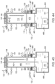
- FIGS. 4 A- 4 H are schematic cross-sectional views of the launching system at different stages of a remote inspection device launching process according to an embodiment described herein.
- FIG. 5 is a flow diagram of a process of recovering a remote inspection device with the launching system of FIG. 1 .
- FIGS. 6 A- 6 H are schematic cross-sectional views of the launching system at different stages of a remote inspection device recovery process according to an embodiment described herein.
- the present disclosure relates to methods and apparatus for launch and recovery of a remote inspection device within a liquid storage tank.
- the tank is accessed by opening an entrance hatch and then injecting a vapor suppression foam across a surface of a stored liquid mass to form a foam layer.
- a launching system having a remote inspection device is attached to the entrance hatch to define a launch and recovery space sealed from an external environment and isolated from the stored liquid mass in the tank via a valve and the foam layer.
- the launch and recovery space is purged of hazardous vapors by injection of an inert gas prior to launch and recovery of the remote inspection device.
- the surface of the stored liquid mass Prior to removal of the launching system, the surface of the stored liquid mass is re-coated with vapor suppression foam.
- FIG. 1 is a cross-sectional view of a launching system 100 for a remote inspection device 150 according to one embodiment.
- the launching system 100 includes a chamber body 102 having one or more sidewalls 104 and a lid 106 at least partially defining a launch and recovery volume 110 .
- the lid 106 is integrally coupled to the sidewalls 104 .
- the lid 106 is removably coupled to the sidewalls 104 .
- the chamber body 102 may have any suitable morphology and dimensions.
- the chamber body 102 has a substantially cylindrical shape.
- the chamber body 102 has a polygonal shape, such as a rectangular shape or the like.
- the chamber body 102 is shaped to correspond with a morphology of an opening or manway in a liquid storage tank.
- the chamber body 102 is fabricated from a material suitable for maintaining a low pressure and inerted environment therein, such as metallic materials, for example aluminum and titanium.
- the chamber body 102 is fabricated from a metal alloy, for example stainless steel, carbon steel, hastelloy, and nickel alloy.
- the chamber body 102 and any equipment or components coupled thereto are electrically bonded to match the electric potentials thereof.
- the chamber body 102 and the equipment or components coupled thereto may be electrically bonded via one or more bonding straps, bus bars, jumper wires, shunts, rods, adhesives, and other suitable electrical connectors.
- the chamber body 102 further contains a winch 140 , a cable 142 , and a remote inspection device 150 therein.
- the winch 140 may be coupled to the chamber body 102 at any suitable location, such as for example, to the lid 106 or a distal end of the sidewalls 104 as depicted in FIG. 1 A .
- the winch 140 is a manual hand winch having a handle 144 disposed external to the launch and recovery volume 110 for manual hand crank operation.
- the winch 140 is a pneumatic winch to which compressed air may be fed in a location external to the launch and recovery volume 110 .
- the winch 140 is a hydraulic winch.
- the cable 142 is fabricated from a material suitable to withstand a high tension generated by the weight of the remote inspection device 150 when coupled thereto, such as a load capacity between about 200 pounds and about 500 pounds.
- the cable 142 is fabricated from a metallic material such as aluminum, titanium, or a metal alloy. In some examples, the cable 142 is fabricated from the same metallic material as the chamber body 102 .
- the remote inspection device 150 includes any suitable submersible apparatus for inspection of liquid-containing vessels.
- the remote inspection device 150 is a submersible vehicle configured to perform tethered or tetherless inspection of liquid-containing vessels.
- the remote inspection device 150 is controlled by a user at a remote location. Additionally or alternatively, the remote inspection device 150 may have autonomous functionality.
- the remote inspection device 150 includes a chassis, a locomotion or propulsion system, a power source, and one or more sensors for performing inspection of liquid-containing vessels.
- the remote inspection device 150 includes a nose cone (not shown) having a substantially conical shape for centering the remote inspection device 150 upon entry into the launching system 100 during recovery thereof.
- the nose cone may be utilized to guide and stabilize the remote inspection device 150 while the remote inspection device 150 is raised through a lower opening of the launching system 100 .
- one or more sets of device guides 152 are optionally disposed within the launch and recovery volume 110 upon which the remote inspection device 150 may be raised and lowered.
- the one or more sets of device guides 152 are utilized to position and usher the remote inspection device 150 during launch and recovery and prevent swinging thereof.
- the one or more sets of device guides 152 may prevent collision of the remote inspection device 150 with the sidewall 104 while the remote inspection device 150 is being raised, lowered, or stored within the chamber body 102 .
- the one or more sets of device guides 152 are rails, tracks, or slots disposed through the launch and recovery volume 110 .
- a pressure relief port 122 , a test port 124 , an inert gas injection port 126 , and an optional wash port 128 are disposed through the one or more sidewalls 104 and/or the lid 106 .
- the pressure relief port 122 , the test port 124 , the inert gas injection port 126 , and the wash port 128 may be disposed at a distal end of the sidewalls 104 .
- the pressure relief port 122 includes a y-type valve, a k-type valve, a spring-loaded valve, or any other suitable type of automatic control valve.
- the pressure relief port 122 functions as a fail-safe to automatically release gases from the launch and recovery volume 110 when an internal pressure exceeds a desired or preset limit.
- the test port 124 provides a coupling for diagnostic equipment (not shown) to monitor one or more conditions of the launch and recovery volume 110 .
- the test port 124 may serve as an adaptor for a pressure gauge, a temperature gauge, or the like.
- the gas injection port 126 facilitates the delivery of one or more gases into the launch and recovery volume 110 , for example, during the launch and recovery of the remote inspection device 150 .
- the inert gas injection port 126 is coupled to a gas supply (not shown) configured to supply one or more inert gases into the launch and recovery volume 110 , such as nitrogen, argon, and the like.
- the pressure relief port 122 , the test port 124 , and the gas injection port 126 are utilized to inert the launch and recovery volume 110 and maintain a slight overpressure of inert gas above ambient atmospheric pressure therein during launch and recovery of the remote inspection device 150 .
- the pressure relief port 122 , the test port 124 , and the gas injection port 126 are disposed in close proximity to one another for easier accessibility to a user.
- the launching system 100 may include the optional wash port 128 .
- the wash port 128 facilitates the delivery of one or more cleaning fluids into the launch and recovery volume 110 .
- the wash port 128 may be coupled to a cleaning fluid supply (not shown) configured to supply one or more cleaning fluids to the launch and recovery volume 110 to clean the remote inspection device 150 , cable 142 , and interior walls of the chamber body 102 .
- Suitable cleaning fluids for use with the launching system 100 include non-corrosive or biodegradable agents.
- the wash port 128 is further coupled to an annular spray device 129 , such as a showerhead, disposed between the winch 140 and the remote inspection device 150 and around the cable 142 .
- the spray device 129 may be coupled to the chamber sidewalls 104 or the lid 106 .
- the spray device 129 is utilized to direct and distribute the cleaning fluids within the interior of the chamber body 102 , such as against the cable 142 , the remote inspection device 150 , and the interior walls of the chamber body 102 .
- One or more lifting lugs 127 are coupled to an exterior surface of the chamber body 102 , such as the sidewalls 104 or the lid 106 . Two lifting lugs 127 are shown coupled to the lid 106 in FIG. 1 A .
- the lifting lugs 127 provide anchor points for one or more cables of a lifting device (not shown) to attach thereto and hoist the launching system 100 onto or off of the liquid storage tank.
- the launching system 100 may be lifted onto a roof of the storage tank via a crane or other suitable device having a hoisting cable attached to the lifting lugs 127 .
- the lifting lugs 127 are formed of a material similar to that of the chamber body 102 , such as aluminum, titanium, or a metal alloy.
- a closure 108 is coupled to the chamber body 102 at a flange 105 and further defines the launch and recovery volume 110 .
- the closure 108 enables opening and closing of the launch and recovery volume 110 to an external environment, such as the interior of the liquid storage tank.
- the closure 108 is a ball valve, a plug valve, or the like.
- the closure 108 is fabricated from a material suitable for maintaining a low pressure environment within the launch and recovery volume 110 , such as metallic materials like aluminum, titanium, stainless steel, and other metal alloys.
- the closure 108 is a knife gate valve or a slide gate valve having a frame 107 and a gate blade 118 .
- the frame 107 and the gate blade 118 are shaped to correspond with the shape of the chamber body 102 .
- the frame 107 may be annular and the gate blade 118 substantially circular.
- the frame 107 and the gate blade 118 may be substantially quadrate.
- the frame 108 has one or more gate seats 109 through which the gate blade 118 is actuated.
- the gate blade 118 is configured to seal the launch and recovery volume 110 from an external environment, for example the interior of the liquid storage tank.
- the closure 108 includes a gate blade actuator (not shown), such as an external hand-wheel threaded onto a screw attached to the gate blade 118 .
- a gate blade actuator such as an external hand-wheel threaded onto a screw attached to the gate blade 118 .
- the screw is axially moved by the wheel, causing the gate blade 118 to be moved in a first or second direction.
- the closure 108 is coupled to a tank adapter 114 on a side thereof opposite the chamber body 102 .
- the tank adapter 114 facilitates coupling of the launching system 100 to an opening of the liquid storage tank, such as a manway or hatchway of the liquid storage tank.
- the tank adapter 114 is fabricated from a material suitable for maintaining a low pressure environment therein, such as metallic materials like aluminum, titanium, stainless steel, and other metal alloys.
- the tank adapter 114 adapts the dimensions of the chamber body 102 and/or closure 108 to dimensions and morphologies of the liquid storage tank opening.
- the tank adapter 114 adapts the diameter of the chamber body 102 adjacent the closure 108 to a diameter of the liquid storage tank opening.
- the tank adapter 114 has an inner diameter lesser than an inner diameter of the chamber body 102 and/or an inner diameter of the closure 108 to account for manways or hatchways having smaller dimensions. Furthermore, the tank adapter 114 may have a lower annular surface 115 wide enough to adapt the launching system 100 to liquid storage tank openings having both narrower and wider diameters or widths, such as openings ranging in diameter/width between about 18 inches and about 36 inches, such as between about 24 inches and about 30 inches.
- the tank adapter 114 has a bolt pattern that matches a bolt pattern of the liquid storage tank opening, enabling direct bolting of the launching system 100 to the liquid storage tank.
- the tank adapter 114 is clamped to the opening of the liquid storage tank by an external clamping system or device, such as a quick-latch system (not shown).
- a quick-latch system (not shown).
- the tank adapter 114 is clamped to the opening of the liquid storage tank by a pull-action latch or toggle clamp, such as a U-hook type clamp, a J-hook type clamp, or the like.
- the utilization of a quick-latch system enables quick and efficient coupling of the launching system 100 to the liquid storage tank opening.
- the lower annular surface 115 of the tank adapter 114 may further include one or more grooves 117 for placement of one or more seals therein (not shown), thus enabling the creation of a hermetic seal between the launching system 100 and the storage tank during coupling.
- the lower annular surface 115 of the tank adapter 114 may include one or more annular grooves 117 therein configured to support one or more o-rings (not shown).
- the one or more seals may be formed any suitable sealing materials, including but not limited to FFKM, PTFE, PEEK.
- the tank adapter 114 may be configured to be coupled to a gasket disposed between the tank adapter 114 and an opening of the liquid storage tank during operation of the launching system 100 .
- the tank adapter 114 includes one or more release ports 132 and one or more injection ports 134 .
- the release ports 132 may include a vent port, a test port, a pressure relief port, and/or the like.
- one or more gauges such as a temperature gauge and a pressure gauge, may be coupled to the release ports 132 .
- the one or more release ports 132 include a pressure relief port substantially similar to the pressure relief port 122 described above.
- the injection ports 134 may include a foam injection port, an inert gas injection port, and/or the like.
- the one or more injection ports 134 include an inert gas injection port substantially similar to the inert gas injection port 126 .
- release ports 132 and the injection ports 134 may be utilized to assess, monitor, and control the conditions of a storage tank vapor gap (e.g. intermediate volume 478 in FIG. 4 D ) prior to opening of the closure 108 and launch or recovery of the remote inspection device 150 .
- a storage tank vapor gap e.g. intermediate volume 478 in FIG. 4 D
- FIG. 2 is a cross-sectional view of a launching system 200 configured to launch and recover the remote inspection device 150 according to one embodiment.
- the launching system 200 is substantially similar to the launching system 100 and includes all the features described with reference to FIG. 1 , but further includes a transport system 260 coupled thereto. Accordingly, only the transport system 260 will be described with reference to FIG. 2 .
- the transport system 260 is configured to facilitate both vertical and horizontal transport of the launching system 200 along a roof of the liquid storage tank, thus enabling quick and efficient coupling of the launching system 200 to the opening of the liquid storage tank for engagement therewith.
- the transport system 260 is removably (or fixedly) coupled to the chamber body 102 of the launching system 200 at an end thereof adjacent to the closure 108 and tank adapter 114 .
- the transport system 260 may include three or more wheel assemblies 262 and wheel mounts 264 to facilitate horizontal movement thereof. In such examples, the wheel mounts 264 may be directly or indirectly coupled to the chamber body 102 .
- the transport system 260 includes a transport frame 266 for coupling the wheel mounts 264 to the chamber body 102 .
- the transport frame 266 may include an annular frame coupled to and substantially surrounding a circumference of the chamber body 102 .
- the wheel mounts 264 are attached to the transport frame 266 using pivoting arms and ball joints (not shown), thereby providing more freedom for placement of the wheel assemblies 262 relative to the transport frame 266 in case of obstructions around the opening of the liquid storage tank, such as rolling ladders.
- the wheel assemblies 262 may generally include a wheel, a wheel frame, and a brake.
- the wheel assemblies 262 include a caster, such as a swivel caster or a ball caster.
- the wheel assemblies 262 facilitate 360° directional horizontal movement of the launching system 200 .
- the wheel assemblies 262 , the wheel mounts 264 , and the transport frame 266 are fabricated from any suitable materials capable of withstanding a load capacity of the launching system 200 and the remote inspection device 150 .
- the wheel mounts 264 and the transport frame 266 are fabricated from metallic materials such as aluminum, titanium, stainless steel, and other metallic alloys.
- the wheels are pneumatic or foam-filled wheels configured to withstand the load capacities described above, in addition to shock loads from impacts caused by uneven surfaces of the liquid storage tank. Accordingly, the wheels may absorb the impact shock and cushion the launching system 200 during transport thereof.
- the transport system 260 further includes a vertical actuator to facilitate vertical movement of the launching system 200 , thus enabling lowering and/or raising of the launching system 200 to/from the opening of the liquid storage tank.
- the vertical actuator is a mechanical actuator, a hydraulic actuator, a pneumatic actuator, or the like.
- the vertical actuator may be a mechanical actuator configured to convert rotary motion of a hand-wheel or handle into linear vertical displacement of the launching system 200 , such as a jack screw, a house jack, or the like.
- FIG. 3 illustrates a flow diagram of a representative method 300 of launching a remote inspection device, such as the remote inspection device 150 , with the launching systems 100 , 200 of FIG. 1 and FIG. 2 .
- FIGS. 4 A- 4 H illustrate schematic, cross-sectional views of the launching system 100 at different stages of the method 300 .
- FIGS. 4 A- 4 H depict the launching system 100 , it should be understood that the method 300 may be performed utilizing the launching system 200 as well.
- the method 300 for launching the remote inspection device 150 has multiple operations.
- the operations can be carried out in any suitable order or simultaneously (except where the context excludes the possibility), and the method can include one or more other operations which are carried out before any of the defined operations, between two of the defined operations, or after all of the defined operations (except where the context excludes the possibility). Not all embodiments include all the operations described.
- the method 300 includes controlling the volatilization of a stored liquid mass in a liquid storage tank by injecting a layer of vapor suppressing foam thereon at operation 310 .
- an inerted launching system such as the launching system 100
- An inert gas is then supplied to a space above the liquid mass in the liquid storage tank at operation 330 .
- a valve integrated with the launching system such as the closure 108 , is opened, thus exposing an internal volume of the launching system to the vapor space.
- a remote inspection device disposed within the launching system such as the remote inspection device 150 , is transferred into the liquid storage tank via a winch and cable.
- the remote inspection device Upon reaching a bottom surface of the liquid storage tank, the remote inspection device detaches itself from the cable at operation 360 .
- the cable is rewound into the launching system and the closure is closed.
- the method 300 begins with operation 310 , corresponding to FIGS. 4 A and 4 B .
- a cover plate 462 is removed from an opening 464 of a liquid storage tank 400 containing a liquid mass 466 .
- the liquid storage tank 400 may be any suitable type of storage tank for the storage of liquids, including but not limited to fixed roof tanks, external floating roof tanks, internal floating roof tanks, spherical tanks, bullet tanks, and the like.
- Examples of liquids 466 stored in the liquid storage tank 400 may include crude oil, gasoline, naphtha, diesel, kerosene, fuel oil, other petroleum combustibles and distillates, and the like.
- the opening 464 may be any suitable opening in the liquid storage tank 400 , such as a manway, manhole, or other type of opening.
- a vapor suppression foam 470 may be immediately injected through the opening 464 to form a layer of the vapor suppression foam 470 atop the liquid mass 466 .
- the vapor suppression foam 470 is a firefighting foam, such as a class B foam designed to contain explosive vapors produced by flammable liquids.
- the vapor suppression foam 470 is a synthetic foam, such as an aqueous film forming foam (AFFF) or an alcohol-resistant aqueous film-forming foam (AR-AFFF).
- the vapor suppression foam 470 is a protein based foam, such as a regular protein foam (P), a fluoroprotein foam (FP), a film-forming fluoroprotein foam (FFFP), an alcohol-resistant fluoroprotein foam (AR-FP), or an alcohol-resistant film-forming fluoroprotein foam (AR-FFFP).
- the vapor suppression foam 470 is injected into the vapor space 468 via a foam delivery system 472 .
- the foam delivery system 472 is a handheld compressed air foam system.
- the launching system 100 is coupled to the liquid storage tank 400 , depicted in FIGS. 4 C and 4 D .
- the coupling of the launching system 100 and the opening 464 forms an intermediate volume 478 between the layer of vapor suppression foam 470 or liquid mass 466 and the closure 108 .
- the launching system 100 is lowered onto the opening 464 by a crane or other suitable lifting device (not shown) attached to one or more lifting lugs coupled to the chamber body 102 .
- the launching system 100 is lowered onto the opening 464 by adjusting the vertical actuator of the transport system 260 to a desired height after the launching system 100 has already been hoisted unto a roof of the liquid storage tank 400 and transported thereacross to the opening 464 .
- the tank adapter 114 is bolted or clamped to a flange 465 of the opening 464 using a latching mechanism 469 .
- a gasket 467 is installed on the flange 465 prior to coupling with the tank adapter 114 , thus enabling a hermetic seal between the opening 464 and the launching system 100 .
- the gasket 467 may be formed of any suitable sealing materials, including but not limited to FFKM, PTFE, PEEK.
- the lower annular surface 115 of the tank adapter 114 may include grooves 117 already having one or more seals disposed therein, such as o-rings, thus eliminating the need for utilizing the gasket 467 .
- the launch and recovery volume 110 and the intermediate volume 478 are purged and inerted by removing and displacing gases therein with an inert gas.
- the initially-present gases may be displaced by an inert gas such as nitrogen, argon, and the like.
- the inert gas is injected into the launch and recovery volume 110 through the inert gas injection port 126 , while the initially-present gas species of the launch and recovery volume 110 are purged through the pressure relief port 122 .
- the inert gas is injected into the intermediate volume 478 through the one or more injection ports 134 , while the initially-present gas species of the intermediate volume 478 are removed through the one or more release ports 132 .
- An active, slight over-pressurization is then maintained in both the intermediate volume 478 and the launch and recovery volume 110 , such as a pressure less than 1 psi.
- the closure 108 is opened, thus desegregating the launch and recovery volume 110 and the intermediate volume 478 and forming a combined inert volume 480 between the launching system 100 and the liquid mass 466 , as depicted in FIG. 4 E .
- Desegregation of the launch and recovery volume 110 and the intermediate volume 478 equalizes the physical conditions, such as temperature and pressure, therebetween.
- the closure 108 is opened by manually sliding the gate blade 118 out from the one or more gate seats 109 .
- the gate blade 118 is actuated by operating a gate blade actuator, such as by rotating a hand-wheel.
- the remote inspection device 150 is transferred into the liquid storage tank 400 at operation 350 , depicted in FIG. 4 F .
- the remote inspection device 150 is lowered through the combined inert volume 480 and into the liquid mass 466 by rotating the handle 144 of the winch 140 and unwinding the cable 142 .
- the winch 140 is operated via an electronic controller to wind and unwind the cable 142 , thus raising and lowering the remote inspection device 150 through the combined inert volume 480 .
- the remote inspection device 150 is moved along one or more sets of guides 152 as it is transferred through the combined inert volume 480 .
- the one or more sets of device guides 152 help stabilize the remote inspection device 150 as it is raised and lowered through the chamber body 102 , preventing swinging thereof and collisions of the remote inspection device 150 against the sidewalls 104 .
- a negative buoyancy of the remote inspection device 150 enables it to sink to a storage tank floor 401 under its own weight as the cable 142 is unwound.
- the remote inspection device 150 automatically powers on as it is lowered into the liquid storage tank 400 .
- the remote inspection device 150 is automatically activated and/or inactivated as it reaches a desired preset depth in the liquid mass 466 during launch and recovery.
- the remote inspection device 150 includes one or more mechanical pressure switches integrated into a power interlock system (not shown) therein. The utilization of the mechanical pressure switches enables the activation and/or inactivation of the remote inspection device 150 without application of power, thus preventing ignitions. Further, the mechanical pressure switches ensure that the remote inspection device 150 is only powered on when submerged a desired depth below the surface of the liquid mass 466 , thus facilitating activation of the remote inspection device 150 in an environment having a reduced oxygen content.
- the remote inspection device 150 detaches from the cable 142 upon reaching the storage tank floor 401 .
- the remote inspection device 150 may then proceed with inspection of the liquid storage tank 400 as the cable 142 is reeled back into the chamber body 102 .
- the closure 108 is closed after the cable 142 has been reeled back in the chamber body 102 .
- FIG. 5 illustrates a flow diagram of a representative method 500 of recovering a remote inspection device, such as the remote inspection device 150 , with the launching systems 100 , 200 of FIG. 1 and FIG. 2 .
- FIGS. 6 A- 6 H illustrate schematic, cross-sectional views of the launching system 100 at different stages of the method 500 .
- FIGS. 6 A- 6 H depict the launching system 100 , it should be understood that the method 500 may be performed utilizing the launching system 200 as well.
- the method 500 for recovery of the remote inspection device 150 has multiple operations.
- the operations can be carried out in any suitable order or simultaneously (except where the context excludes the possibility), and the method can include one or more other operations which are carried out before any of the defined operations, between two of the defined operations, or after all of the defined operations (except where the context excludes the possibility). Not all embodiments include all the operations described.
- the method 500 includes opening the closure of the launching system at operation 510 and lowering the cable into the liquid storage tank at operation 520 .
- the remote inspection device already deployed in the liquid storage tank latches onto the cable at the liquid storage tank floor.
- the remote inspection device is then hoisted through the liquid storage tank and into the launching system at operation 540 .
- the closure is closed, the internal volume of the launching system is re-inerted, and the liquid mass within the liquid storage tank is re-coated with the vapor suppression foam.
- the launching system is then removed from the liquid storage tank at operation 570 and the liquid storage tank is sealed at operation 580 .
- the method 500 begins with operation 510 , corresponding to FIG. 6 A .
- the closure 108 is opened, thus once again combining the launch and recovery volume 110 and the intermediate volume 478 to form the combined inert volume 480 , depicted in FIG. 6 B . Opening of the closure 108 equalizes the physical conditions between the launch and recovery volume 110 and the intermediate volume 478 , such as temperature and pressure.
- the closure 108 may be opened by manually sliding the gate blade 118 out from the one or more gate seats 109 .
- the gate blade 118 may be actuated by operating a gate blade actuator, such as a hand-wheel.
- the launch and recovery volume 110 and/or the intermediate volume 478 may be re-inerted prior to opening of the closure 108 .
- the launch and recovery volume 110 and the intermediate volume 478 are purged and re-inerted by removing and displacing gases therein with an inert gas.
- the inert gas is injected into the launch and recovery volume 110 through the inert gas injection port 126 , while the previously present gas species of the launch and recovery volume 110 are purged through the pressure relief port 122 .
- the inert gas is injected into the intermediate volume 478 through the one or more injection ports 134 , while the previously present gas species of the intermediate volume 478 are removed through the one or more release ports 132 .
- the cable 142 is unwound from the winch 140 at operation 520 and lowered into the liquid storage tank 400 until an end of the cable 142 reaches the storage tank floor 401 .
- the cable 142 is unwound by manually rotating the handle 144 of the winch 140 .
- the cable is unwound by operation of a pneumatic or hydraulic controller coupled to the winch 140 .
- the remote inspection device 150 locates the cable 142 at the storage tank floor 40 and attaches itself thereto. After attachment of the remote inspection device 150 to the cable 142 , the remote inspection device 150 is hoisted through the liquid storage tank 400 and into the chamber body 102 of the launching system 100 at operation 540 , as depicted in FIG. 6 D . As described above, the remote inspection device 150 is hoisted through the liquid storage tank 400 and the chamber body 102 by winding of the cable 142 . At a desired preset depth of the liquid mass 466 , the remote inspection device 150 may automatically power off by operation of one or more mechanical pressure switches integrated therein.
- the remote inspection device 150 may be coupled to the one or more sets of device guides 152 to position and usher the remote inspection device 150 to a final storage position within the launching system 100 .
- the remote inspection device 150 may be guided along one or more sets of tracks longitudinally disposed within the chamber body 102 as it is hoisted through the combined inert volume 480 .
- one or more cleaning fluids may be supplied to the launch and recovery volume 110 by the wash port 128 .
- the wash port 128 and the spray device 129 may be utilized to wash the remote inspection device 150 , the cable 142 , the interior walls of the chamber body 102 , and other components or equipment within the launch and recovery volume 110 .
- the cleaning fluids may be supplied to the launch and recovery volume 110 as the remote inspection device 150 is raised therethrough, thus washing the cable 142 and the remote inspection device 150 as it is recovered from the liquid mass 466 .
- the cleaning fluids are supplied to the launch and recovery volume 110 after the remote inspection device 150 has been recovered and is secured within the launching system 100 .
- the closure 108 is closed.
- the closure 108 may be closed by manually sliding the gate blade 118 into the one or more gate seats 109 of the frame 107 .
- the gate blade 118 may be actuated by operating a gate blade actuator, such as a hand-wheel. Closing of the closure 108 results in the reformation of the launch and recovery volume 110 within which the remote inspection device 150 is stored. At this point, the launch and recovery volume 110 is re-inerted, as described above with reference to operations 330 and 510 .
- the vapor suppression foam 470 may be re-injected into the opening 464 at operation 560 to reform the layer of vapor suppression foam 470 atop the liquid mass 466 .
- any further volatilization and release of vapors form the liquid mass 466 is suppressed prior to removal of the launching system 100 from the opening 464 .
- the vapor suppression foam 470 is injected into the opening 464 through a foam injection port 134 disposed through the tank adapter 114 .
- the launching system 100 is uncoupled and removed from the opening 464 of the liquid storage tank 400 .
- the launching system 100 is uncoupled from the opening 464 by removing or releasing a latching mechanism 469 connecting the tank adapter 114 to the flange 465 .
- the latching mechanism 469 includes one or more bolts disposed through the tank adapter 114 and the flange 465 .
- the latching mechanism 469 includes a clamp connecting the tank adapter 114 and the flange 465 . Upon removal or release of the latching mechanism 469 , the launching system 100 is removed from the opening 464 .
- the launching system 100 is raised from the opening 464 by a crane or other suitable lifting device (not shown) attached to one or more lifting lugs thereof. In an alternative embodiment, the launching system 100 is raised away from the opening 464 by adjusting the transport system 260 to a desired height. As depicted in FIG. 6 H , once the launching system 100 is removed from the opening 464 , the cover plate 462 is resealed against the opening 464 at operation 580 .
- one or more aspects disclosed herein may be utilized to deploy a remote inspection device within a liquid storage tank, such as a hydrocarbon storage tank, containing a hazardous environment therein.
- a liquid storage tank such as a hydrocarbon storage tank
- hazardous vapors within a hydrocarbon storage tank are contained within the tank by utilization of a vapor suppression foam and an inerted remote inspection device launching system.
- the utilization of the vapor suppression foam and the inerted launching system prevents the escape of volatile and hazardous vapors from releasing into the surrounding environment during storage tank inspection.
- the remote inspection device launched into the storage tank is configured to activate in an environment with low oxygen content and without the application of external power, thus preventing ignition. Accordingly, the aspects described herein prevent the exposure of nearby personnel to hazards normally associated with hydrocarbon storage facilities.
Abstract
Description
Claims (20)
Priority Applications (3)
| Application Number | Priority Date | Filing Date | Title |
|---|---|---|---|
| US16/539,697 US11925824B2 (en) | 2018-08-13 | 2019-08-13 | Method and apparatus for launching and recovering a remote inspection device from a volatile liquid storage tank |
| US18/090,200 US20230166146A1 (en) | 2018-08-13 | 2022-12-28 | Method and apparatus for launching and recovering a remote inspection device |
| US18/090,178 US11931612B2 (en) | 2018-08-13 | 2022-12-28 | Method and apparatus for launching and recovering a remote inspection device from a volatile fluid storage tank |
Applications Claiming Priority (2)
| Application Number | Priority Date | Filing Date | Title |
|---|---|---|---|
| US201862718145P | 2018-08-13 | 2018-08-13 | |
| US16/539,697 US11925824B2 (en) | 2018-08-13 | 2019-08-13 | Method and apparatus for launching and recovering a remote inspection device from a volatile liquid storage tank |
Related Child Applications (2)
| Application Number | Title | Priority Date | Filing Date |
|---|---|---|---|
| US18/090,178 Division US11931612B2 (en) | 2018-08-13 | 2022-12-28 | Method and apparatus for launching and recovering a remote inspection device from a volatile fluid storage tank |
| US18/090,200 Division US20230166146A1 (en) | 2018-08-13 | 2022-12-28 | Method and apparatus for launching and recovering a remote inspection device |
Publications (2)
| Publication Number | Publication Date |
|---|---|
| US20200047016A1 US20200047016A1 (en) | 2020-02-13 |
| US11925824B2 true US11925824B2 (en) | 2024-03-12 |
Family
ID=69405356
Family Applications (3)
| Application Number | Title | Priority Date | Filing Date |
|---|---|---|---|
| US16/539,697 Active 2042-11-07 US11925824B2 (en) | 2018-08-13 | 2019-08-13 | Method and apparatus for launching and recovering a remote inspection device from a volatile liquid storage tank |
| US18/090,178 Active US11931612B2 (en) | 2018-08-13 | 2022-12-28 | Method and apparatus for launching and recovering a remote inspection device from a volatile fluid storage tank |
| US18/090,200 Pending US20230166146A1 (en) | 2018-08-13 | 2022-12-28 | Method and apparatus for launching and recovering a remote inspection device |
Family Applications After (2)
| Application Number | Title | Priority Date | Filing Date |
|---|---|---|---|
| US18/090,178 Active US11931612B2 (en) | 2018-08-13 | 2022-12-28 | Method and apparatus for launching and recovering a remote inspection device from a volatile fluid storage tank |
| US18/090,200 Pending US20230166146A1 (en) | 2018-08-13 | 2022-12-28 | Method and apparatus for launching and recovering a remote inspection device |
Country Status (1)
| Country | Link |
|---|---|
| US (3) | US11925824B2 (en) |
Families Citing this family (3)
| Publication number | Priority date | Publication date | Assignee | Title |
|---|---|---|---|---|
| US20230173551A1 (en) * | 2020-04-06 | 2023-06-08 | Square Robot, Inc. | Systems, methods and apparatus for safe launch and recovery of an inspection vehicle |
| NL2027794B1 (en) * | 2021-03-22 | 2022-09-29 | Claeys Deef | Assembly for sensory and visual inspection of a closed storage tank |
| BE1029681B1 (en) * | 2021-08-13 | 2023-03-13 | Rosen Swiss Ag | Method for inspecting a tank, lock device and arrangement, comprising a tank, a lock device and an inspection device |
Citations (34)
| Publication number | Priority date | Publication date | Assignee | Title |
|---|---|---|---|---|
| GB2196715A (en) * | 1986-10-27 | 1988-05-05 | British Gas Plc | Method of launching a pig into a pipeline |
| US5037486A (en) * | 1990-08-22 | 1991-08-06 | Subaqueous Services, Inc. | Apparatus and method for cleaning liquid storage tank |
| US5138891A (en) * | 1990-02-20 | 1992-08-18 | Johnson Ronald G | Gauge well system |
| US5363935A (en) * | 1993-05-14 | 1994-11-15 | Carnegie Mellon University | Reconfigurable mobile vehicle with magnetic tracks |
| US5435405A (en) * | 1993-05-14 | 1995-07-25 | Carnegie Mellon University | Reconfigurable mobile vehicle with magnetic tracks |
| US5451135A (en) * | 1993-04-02 | 1995-09-19 | Carnegie Mellon University | Collapsible mobile vehicle |
| EP0736722A1 (en) * | 1995-04-04 | 1996-10-09 | British Gas plc | Apparatus for introducing into and removing from a pipe a device which is advanced and retracted by a cable |
| US5640982A (en) * | 1994-11-18 | 1997-06-24 | Landry Service Co. Inc. | Tank cleaning system using collapsible robotic tank entry vehicle |
| US5819863A (en) * | 1996-08-28 | 1998-10-13 | Lockheed Martin Idaho Technologies Company | Vehicle for carrying an object of interest |
| US5942687A (en) * | 1998-04-01 | 1999-08-24 | The United States Of America As Represented By The Secretary Of The Navy | Method and apparatus for in situ measurement of corrosion in filled tanks |
| US6104970A (en) * | 1998-02-17 | 2000-08-15 | Raytheon Company | Crawler inspection vehicle with precise mapping capability |
| US20040016755A1 (en) * | 2002-07-29 | 2004-01-29 | Intank, Inc., A Maryland Corporation | Removable hatch cover for an internal floating roof manway |
| US20040036859A1 (en) * | 2002-08-20 | 2004-02-26 | Intank, Inc. | Method for inspecting an internal floating roof in a liquid-containing storage tank |
| US20040045379A1 (en) * | 2002-09-10 | 2004-03-11 | Intank, Inc. | Hydraulic and electric umbilical connection for an inspection vehicle for inspecting a liquid-filled tank |
| US20040134518A1 (en) * | 2002-12-23 | 2004-07-15 | Catalyst Services, Inc. | Cleaning and/or inspecting robot for hazardous environments including catalyst removal |
| US20060054202A1 (en) * | 2004-09-14 | 2006-03-16 | Luke Stephen A | Remotely operated cleaning device, especially suitable for storage tanks on vessels |
| US20060054189A1 (en) * | 2004-09-14 | 2006-03-16 | Luke Stephen A | Remotely operated cleaning device, especially suitable for storage tanks on vessels |
| US20080148876A1 (en) * | 2000-04-20 | 2008-06-26 | Vince Hock | System and method for accessing ferrous surfaces normally accessible only with special effort |
| US7467560B2 (en) | 2002-09-24 | 2008-12-23 | Berkeley Springs Instruments Llc | Broadband long pulse ultrasonic inspection |
| US20090133515A1 (en) * | 2007-11-26 | 2009-05-28 | Air Products And Chemicals, Inc. | Devices and Methods For Performing Inspections, Repairs, and/or Other Operations Within Vessels |
| US20100180672A1 (en) | 2008-12-20 | 2010-07-22 | William Thor Zollinger | Methods for inspecting atmospheric storage tanks above ground and in floating vessels |
| US20100294761A1 (en) * | 2009-05-21 | 2010-11-25 | Joseph Riordan | Vapor barrier for flammable liquid storage tanks |
| CN102091706A (en) | 2009-12-09 | 2011-06-15 | 天津工程师范学院 | Hose and cable winding system of mobile tank cleaning robot |
| US8122780B1 (en) * | 2008-03-20 | 2012-02-28 | The United States Of America As Represented By The United States Department Of Energy | Explosion proof vehicle for tank inspection |
| NO334827B1 (en) | 2012-11-15 | 2014-06-10 | Dev Lofoten As | Water pipes Tools inserter |
| CN105215029A (en) | 2015-11-17 | 2016-01-06 | 北京石油化工学院 | A kind of oil storage tank robot cleaning system and method |
| US20160101304A1 (en) * | 2014-10-12 | 2016-04-14 | Keith A. Langenbeck | Multi-Blanket Inert Gas Rail Car Fire Suppression |
| US9540907B1 (en) * | 2013-08-28 | 2017-01-10 | Jaco du Plessis | In-line fire control system for a hydrocarbon fluid stream |
| CN107607465A (en) * | 2017-10-26 | 2018-01-19 | 西南石油大学 | A kind of in-service Large Oil Tank Corrosion of base plate detection robot |
| US20180088592A1 (en) * | 2016-09-26 | 2018-03-29 | California Institute Of Technology | Autonomous robotic airship inspection system for large-scale tank interiors |
| WO2018104790A1 (en) * | 2016-12-07 | 2018-06-14 | Abb Schweiz Ag | Liquid tank inspection including device for launching submersible |
| US20190201947A1 (en) * | 2016-05-18 | 2019-07-04 | Worleyparsons Services Pty Ltd | Device for removing catalyst and other material from refinery and petrochemical reactors and other vessels |
| US20190325668A1 (en) * | 2016-12-07 | 2019-10-24 | Abb Schweiz Ag | Submersible inspection system |
| US20200363804A1 (en) * | 2017-12-15 | 2020-11-19 | Tankbots, Inc. | Methods for handling a mobile platform in a tank containing non-conductive hazardous substances |
Family Cites Families (1)
| Publication number | Priority date | Publication date | Assignee | Title |
|---|---|---|---|---|
| US8616398B2 (en) * | 2009-05-21 | 2013-12-31 | Joseph Riordan | Vapor barrier structure |
-
2019
- 2019-08-13 US US16/539,697 patent/US11925824B2/en active Active
-
2022
- 2022-12-28 US US18/090,178 patent/US11931612B2/en active Active
- 2022-12-28 US US18/090,200 patent/US20230166146A1/en active Pending
Patent Citations (41)
| Publication number | Priority date | Publication date | Assignee | Title |
|---|---|---|---|---|
| GB2196715A (en) * | 1986-10-27 | 1988-05-05 | British Gas Plc | Method of launching a pig into a pipeline |
| US5138891A (en) * | 1990-02-20 | 1992-08-18 | Johnson Ronald G | Gauge well system |
| US5037486A (en) * | 1990-08-22 | 1991-08-06 | Subaqueous Services, Inc. | Apparatus and method for cleaning liquid storage tank |
| US5451135A (en) * | 1993-04-02 | 1995-09-19 | Carnegie Mellon University | Collapsible mobile vehicle |
| US5363935A (en) * | 1993-05-14 | 1994-11-15 | Carnegie Mellon University | Reconfigurable mobile vehicle with magnetic tracks |
| US5435405A (en) * | 1993-05-14 | 1995-07-25 | Carnegie Mellon University | Reconfigurable mobile vehicle with magnetic tracks |
| US5640982A (en) * | 1994-11-18 | 1997-06-24 | Landry Service Co. Inc. | Tank cleaning system using collapsible robotic tank entry vehicle |
| EP0736722A1 (en) * | 1995-04-04 | 1996-10-09 | British Gas plc | Apparatus for introducing into and removing from a pipe a device which is advanced and retracted by a cable |
| US5819863A (en) * | 1996-08-28 | 1998-10-13 | Lockheed Martin Idaho Technologies Company | Vehicle for carrying an object of interest |
| US6104970A (en) * | 1998-02-17 | 2000-08-15 | Raytheon Company | Crawler inspection vehicle with precise mapping capability |
| US5942687A (en) * | 1998-04-01 | 1999-08-24 | The United States Of America As Represented By The Secretary Of The Navy | Method and apparatus for in situ measurement of corrosion in filled tanks |
| US20080148876A1 (en) * | 2000-04-20 | 2008-06-26 | Vince Hock | System and method for accessing ferrous surfaces normally accessible only with special effort |
| US20040016755A1 (en) * | 2002-07-29 | 2004-01-29 | Intank, Inc., A Maryland Corporation | Removable hatch cover for an internal floating roof manway |
| US20040036859A1 (en) * | 2002-08-20 | 2004-02-26 | Intank, Inc. | Method for inspecting an internal floating roof in a liquid-containing storage tank |
| US20040045379A1 (en) * | 2002-09-10 | 2004-03-11 | Intank, Inc. | Hydraulic and electric umbilical connection for an inspection vehicle for inspecting a liquid-filled tank |
| US7017432B2 (en) | 2002-09-10 | 2006-03-28 | Ast Services Llc | Hydraulic and electric umbilical connection for an inspection vehicle for inspecting a liquid-filled tank |
| US20050087362A1 (en) * | 2002-09-10 | 2005-04-28 | Silverman Eugene B. | Hydraulic and electric umbilical connection for an inspection vehicle for inspecting a liquid-filled tank |
| US7467560B2 (en) | 2002-09-24 | 2008-12-23 | Berkeley Springs Instruments Llc | Broadband long pulse ultrasonic inspection |
| US20040134518A1 (en) * | 2002-12-23 | 2004-07-15 | Catalyst Services, Inc. | Cleaning and/or inspecting robot for hazardous environments including catalyst removal |
| US20060054202A1 (en) * | 2004-09-14 | 2006-03-16 | Luke Stephen A | Remotely operated cleaning device, especially suitable for storage tanks on vessels |
| US20060054189A1 (en) * | 2004-09-14 | 2006-03-16 | Luke Stephen A | Remotely operated cleaning device, especially suitable for storage tanks on vessels |
| US20090133515A1 (en) * | 2007-11-26 | 2009-05-28 | Air Products And Chemicals, Inc. | Devices and Methods For Performing Inspections, Repairs, and/or Other Operations Within Vessels |
| US20120125128A1 (en) * | 2007-11-26 | 2012-05-24 | Air Products And Chemicals, Inc. | System for performing inspections, repairs, and/or other operations within vessels |
| US8122780B1 (en) * | 2008-03-20 | 2012-02-28 | The United States Of America As Represented By The United States Department Of Energy | Explosion proof vehicle for tank inspection |
| US20100180672A1 (en) | 2008-12-20 | 2010-07-22 | William Thor Zollinger | Methods for inspecting atmospheric storage tanks above ground and in floating vessels |
| US20100294761A1 (en) * | 2009-05-21 | 2010-11-25 | Joseph Riordan | Vapor barrier for flammable liquid storage tanks |
| CN102091706A (en) | 2009-12-09 | 2011-06-15 | 天津工程师范学院 | Hose and cable winding system of mobile tank cleaning robot |
| NO334827B1 (en) | 2012-11-15 | 2014-06-10 | Dev Lofoten As | Water pipes Tools inserter |
| US9540907B1 (en) * | 2013-08-28 | 2017-01-10 | Jaco du Plessis | In-line fire control system for a hydrocarbon fluid stream |
| US20160101304A1 (en) * | 2014-10-12 | 2016-04-14 | Keith A. Langenbeck | Multi-Blanket Inert Gas Rail Car Fire Suppression |
| CN105215029A (en) | 2015-11-17 | 2016-01-06 | 北京石油化工学院 | A kind of oil storage tank robot cleaning system and method |
| US20190201947A1 (en) * | 2016-05-18 | 2019-07-04 | Worleyparsons Services Pty Ltd | Device for removing catalyst and other material from refinery and petrochemical reactors and other vessels |
| US20180088592A1 (en) * | 2016-09-26 | 2018-03-29 | California Institute Of Technology | Autonomous robotic airship inspection system for large-scale tank interiors |
| WO2018104790A1 (en) * | 2016-12-07 | 2018-06-14 | Abb Schweiz Ag | Liquid tank inspection including device for launching submersible |
| US20190287688A1 (en) | 2016-12-07 | 2019-09-19 | Abb Schweiz Ag | Liquid tank inspection including device for launching submersible |
| US20190325668A1 (en) * | 2016-12-07 | 2019-10-24 | Abb Schweiz Ag | Submersible inspection system |
| CN107607465A (en) * | 2017-10-26 | 2018-01-19 | 西南石油大学 | A kind of in-service Large Oil Tank Corrosion of base plate detection robot |
| US20200363804A1 (en) * | 2017-12-15 | 2020-11-19 | Tankbots, Inc. | Methods for handling a mobile platform in a tank containing non-conductive hazardous substances |
| US20210018396A1 (en) * | 2017-12-15 | 2021-01-21 | Tankbots, Inc. | Methods for performing tasks in a tank containing hazardous substances |
| US20210089033A1 (en) * | 2017-12-15 | 2021-03-25 | Tankbots, Inc. | Methods for controlling charge accumulation while operating a mobile platform immersed in a hazardous, non-conductive substance |
| US20210116419A1 (en) * | 2017-12-15 | 2021-04-22 | Tankbots, Inc. | Voltage differential reduction methods used while retrieving a mobile platform from a tank containing a hazardous, non-conductive substance |
Non-Patent Citations (2)
| Title |
|---|
| Schempf et al, Distribution Gasline Robotics and Automation focusing on Explorer: Long-Range Untethered Real-Time Live Gas Main Robotic Inspection System, Version Final Report (Year: 2005). * |
| Schempf, Neptune: Above-Ground Storage Tank Inspection Robot System, IEEE (Year: 1994). * |
Also Published As
| Publication number | Publication date |
|---|---|
| US20230138010A1 (en) | 2023-05-04 |
| US11931612B2 (en) | 2024-03-19 |
| US20200047016A1 (en) | 2020-02-13 |
| US20230166146A1 (en) | 2023-06-01 |
Similar Documents
| Publication | Publication Date | Title |
|---|---|---|
| US11931612B2 (en) | Method and apparatus for launching and recovering a remote inspection device from a volatile fluid storage tank | |
| US9725134B2 (en) | Ship breaking down arrangement and method therefore | |
| US9878761B2 (en) | Large subsea package deployment methods and devices | |
| US20100180672A1 (en) | Methods for inspecting atmospheric storage tanks above ground and in floating vessels | |
| NO321484B1 (en) | Vessel for floating production, storage and unloading, with internal turntable anchorage with an explosion prevention system | |
| EP1294538B1 (en) | Hole cutting tool and method | |
| US20200406809A1 (en) | Towable Fluid Storage Tank Trailer | |
| US4112863A (en) | Barge-supported crane with hydraulically actuated ram corner lift means | |
| EP3102832A1 (en) | Foot valve for submergible pumps | |
| US5025972A (en) | Apparatus for patching a hole in the hull of a moving ship | |
| JP3485321B2 (en) | A device for loading / unloading buoys in the receiving space at the bottom of the ship | |
| US10961047B2 (en) | Internal floating roof transfer tank system | |
| PT1227970E (en) | Method and apparatus for preventing cargo spills | |
| WO2011084143A1 (en) | Methods for inspecting atmospheric storage tanks above ground and in floating vessels | |
| KR101386693B1 (en) | Plant for recovering a polluting fluid contained in the tanks of a sunken vessel | |
| US20140076227A1 (en) | Marine Vessel Having Modular Mission Pods | |
| CA1187341A (en) | Floating device comprising storage holds for bulk freight, such as a hopper dredge | |
| US3696975A (en) | Submerged pump removal system | |
| IE20200211A1 (en) | Zero entry sediment removal from storage tanks | |
| JPH0577781A (en) | Traffic device for tanker | |
| JPH1016884A (en) | Diving work device for water floating structure bottom surface | |
| CN216269781U (en) | Oil supply module of shipborne tank type helicopter | |
| WO1994008841A1 (en) | An access device | |
| JPS6121439Y2 (en) | ||
| Jansen et al. | CAROL-Robotic Catalyst Removal |
Legal Events
| Date | Code | Title | Description |
|---|---|---|---|
| FEPP | Fee payment procedure |
Free format text: ENTITY STATUS SET TO UNDISCOUNTED (ORIGINAL EVENT CODE: BIG.); ENTITY STATUS OF PATENT OWNER: LARGE ENTITY |
|
| STPP | Information on status: patent application and granting procedure in general |
Free format text: DOCKETED NEW CASE - READY FOR EXAMINATION |
|
| AS | Assignment |
Owner name: PHILLIPS 66 COMPANY, TEXAS Free format text: ASSIGNMENT OF ASSIGNORS INTEREST;ASSIGNORS:STAIRES, TROY L.;MOORE, BENJAMIN C.;SIGNING DATES FROM 20190909 TO 20190913;REEL/FRAME:051084/0813 Owner name: SQUARE ROBOT, INC., MASSACHUSETTS Free format text: ASSIGNMENT OF ASSIGNORS INTEREST;ASSIGNORS:VAGANAY, JEROME;LEVITT, ERIC;O'HALLORAN, WILLIAM;REEL/FRAME:051084/0833 Effective date: 20191112 |
|
| STPP | Information on status: patent application and granting procedure in general |
Free format text: NON FINAL ACTION MAILED |
|
| STPP | Information on status: patent application and granting procedure in general |
Free format text: RESPONSE TO NON-FINAL OFFICE ACTION ENTERED AND FORWARDED TO EXAMINER |
|
| AS | Assignment |
Owner name: PHILLIPS 66 COMPANY, TEXAS Free format text: ASSIGNMENT OF ASSIGNORS INTEREST;ASSIGNOR:SQUARE ROBOT, INC.;REEL/FRAME:061300/0965 Effective date: 20220825 |
|
| STPP | Information on status: patent application and granting procedure in general |
Free format text: EX PARTE QUAYLE ACTION MAILED |
|
| STPP | Information on status: patent application and granting procedure in general |
Free format text: RESPONSE TO EX PARTE QUAYLE ACTION ENTERED AND FORWARDED TO EXAMINER |
|
| STPP | Information on status: patent application and granting procedure in general |
Free format text: NOTICE OF ALLOWANCE MAILED -- APPLICATION RECEIVED IN OFFICE OF PUBLICATIONS |
|
| STPP | Information on status: patent application and granting procedure in general |
Free format text: PUBLICATIONS -- ISSUE FEE PAYMENT VERIFIED |
|
| STCF | Information on status: patent grant |
Free format text: PATENTED CASE |