US11924399B2 - Stereoscopic display device having a barrier panel - Google Patents
Stereoscopic display device having a barrier panel Download PDFInfo
- Publication number
- US11924399B2 US11924399B2 US16/839,944 US202016839944A US11924399B2 US 11924399 B2 US11924399 B2 US 11924399B2 US 202016839944 A US202016839944 A US 202016839944A US 11924399 B2 US11924399 B2 US 11924399B2
- Authority
- US
- United States
- Prior art keywords
- barrier
- region
- regions
- display device
- trigger
- Prior art date
- Legal status (The legal status is an assumption and is not a legal conclusion. Google has not performed a legal analysis and makes no representation as to the accuracy of the status listed.)
- Active, expires
Links
- 230000004888 barrier function Effects 0.000 title claims abstract description 251
- 230000000903 blocking effect Effects 0.000 claims abstract description 72
- 239000000758 substrate Substances 0.000 claims description 20
- 239000004973 liquid crystal related substance Substances 0.000 claims description 11
- 239000010410 layer Substances 0.000 description 16
- 239000012790 adhesive layer Substances 0.000 description 10
- 230000008901 benefit Effects 0.000 description 4
- 239000010409 thin film Substances 0.000 description 4
- 239000011229 interlayer Substances 0.000 description 3
- 238000002161 passivation Methods 0.000 description 3
- 239000000463 material Substances 0.000 description 2
- 239000011358 absorbing material Substances 0.000 description 1
- 230000005540 biological transmission Effects 0.000 description 1
- 230000000593 degrading effect Effects 0.000 description 1
- 230000000694 effects Effects 0.000 description 1
- 210000000887 face Anatomy 0.000 description 1
- 239000011521 glass Substances 0.000 description 1
- 238000000034 method Methods 0.000 description 1
- 230000008054 signal transmission Effects 0.000 description 1
- 230000001360 synchronised effect Effects 0.000 description 1
Images


Classifications
-
- H—ELECTRICITY
- H04—ELECTRIC COMMUNICATION TECHNIQUE
- H04N—PICTORIAL COMMUNICATION, e.g. TELEVISION
- H04N13/00—Stereoscopic video systems; Multi-view video systems; Details thereof
- H04N13/30—Image reproducers
- H04N13/366—Image reproducers using viewer tracking
-
- H—ELECTRICITY
- H04—ELECTRIC COMMUNICATION TECHNIQUE
- H04N—PICTORIAL COMMUNICATION, e.g. TELEVISION
- H04N13/00—Stereoscopic video systems; Multi-view video systems; Details thereof
- H04N13/30—Image reproducers
- H04N13/302—Image reproducers for viewing without the aid of special glasses, i.e. using autostereoscopic displays
- H04N13/31—Image reproducers for viewing without the aid of special glasses, i.e. using autostereoscopic displays using parallax barriers
- H04N13/315—Image reproducers for viewing without the aid of special glasses, i.e. using autostereoscopic displays using parallax barriers the parallax barriers being time-variant
-
- G—PHYSICS
- G02—OPTICS
- G02B—OPTICAL ELEMENTS, SYSTEMS OR APPARATUS
- G02B30/00—Optical systems or apparatus for producing three-dimensional [3D] effects, e.g. stereoscopic images
- G02B30/20—Optical systems or apparatus for producing three-dimensional [3D] effects, e.g. stereoscopic images by providing first and second parallax images to an observer's left and right eyes
- G02B30/22—Optical systems or apparatus for producing three-dimensional [3D] effects, e.g. stereoscopic images by providing first and second parallax images to an observer's left and right eyes of the stereoscopic type
- G02B30/25—Optical systems or apparatus for producing three-dimensional [3D] effects, e.g. stereoscopic images by providing first and second parallax images to an observer's left and right eyes of the stereoscopic type using polarisation techniques
-
- G—PHYSICS
- G02—OPTICS
- G02B—OPTICAL ELEMENTS, SYSTEMS OR APPARATUS
- G02B30/00—Optical systems or apparatus for producing three-dimensional [3D] effects, e.g. stereoscopic images
- G02B30/20—Optical systems or apparatus for producing three-dimensional [3D] effects, e.g. stereoscopic images by providing first and second parallax images to an observer's left and right eyes
- G02B30/26—Optical systems or apparatus for producing three-dimensional [3D] effects, e.g. stereoscopic images by providing first and second parallax images to an observer's left and right eyes of the autostereoscopic type
- G02B30/27—Optical systems or apparatus for producing three-dimensional [3D] effects, e.g. stereoscopic images by providing first and second parallax images to an observer's left and right eyes of the autostereoscopic type involving lenticular arrays
-
- G—PHYSICS
- G02—OPTICS
- G02B—OPTICAL ELEMENTS, SYSTEMS OR APPARATUS
- G02B30/00—Optical systems or apparatus for producing three-dimensional [3D] effects, e.g. stereoscopic images
- G02B30/20—Optical systems or apparatus for producing three-dimensional [3D] effects, e.g. stereoscopic images by providing first and second parallax images to an observer's left and right eyes
- G02B30/26—Optical systems or apparatus for producing three-dimensional [3D] effects, e.g. stereoscopic images by providing first and second parallax images to an observer's left and right eyes of the autostereoscopic type
- G02B30/30—Optical systems or apparatus for producing three-dimensional [3D] effects, e.g. stereoscopic images by providing first and second parallax images to an observer's left and right eyes of the autostereoscopic type involving parallax barriers
-
- G—PHYSICS
- G02—OPTICS
- G02F—OPTICAL DEVICES OR ARRANGEMENTS FOR THE CONTROL OF LIGHT BY MODIFICATION OF THE OPTICAL PROPERTIES OF THE MEDIA OF THE ELEMENTS INVOLVED THEREIN; NON-LINEAR OPTICS; FREQUENCY-CHANGING OF LIGHT; OPTICAL LOGIC ELEMENTS; OPTICAL ANALOGUE/DIGITAL CONVERTERS
- G02F1/00—Devices or arrangements for the control of the intensity, colour, phase, polarisation or direction of light arriving from an independent light source, e.g. switching, gating or modulating; Non-linear optics
- G02F1/01—Devices or arrangements for the control of the intensity, colour, phase, polarisation or direction of light arriving from an independent light source, e.g. switching, gating or modulating; Non-linear optics for the control of the intensity, phase, polarisation or colour
- G02F1/13—Devices or arrangements for the control of the intensity, colour, phase, polarisation or direction of light arriving from an independent light source, e.g. switching, gating or modulating; Non-linear optics for the control of the intensity, phase, polarisation or colour based on liquid crystals, e.g. single liquid crystal display cells
-
- H—ELECTRICITY
- H04—ELECTRIC COMMUNICATION TECHNIQUE
- H04N—PICTORIAL COMMUNICATION, e.g. TELEVISION
- H04N13/00—Stereoscopic video systems; Multi-view video systems; Details thereof
- H04N13/30—Image reproducers
- H04N13/302—Image reproducers for viewing without the aid of special glasses, i.e. using autostereoscopic displays
- H04N13/31—Image reproducers for viewing without the aid of special glasses, i.e. using autostereoscopic displays using parallax barriers
-
- H—ELECTRICITY
- H04—ELECTRIC COMMUNICATION TECHNIQUE
- H04N—PICTORIAL COMMUNICATION, e.g. TELEVISION
- H04N13/00—Stereoscopic video systems; Multi-view video systems; Details thereof
- H04N13/30—Image reproducers
- H04N13/366—Image reproducers using viewer tracking
- H04N13/373—Image reproducers using viewer tracking for tracking forward-backward translational head movements, i.e. longitudinal movements
Definitions
- the present disclosure relates to a stereoscopic display device including a barrier panel having blocking regions and transmitting regions.
- a display device includes a display panel for realizing an image.
- the display module may include a liquid crystal panel having a liquid crystal, and an OLED panel having an organic light-emitting element.
- the display device may realize a stereoscopic image using the position difference of two eyes.
- a stereoscopic display device realizing the stereoscopic image may provide different images to the left eye and the right eye of a viewer by using the difference of images due to the position difference of the two eyes, that is, the binocular disparity.
- the stereoscopic display device includes an eyeglasses type using a shutter and a non-glasses type using a barrier panel.
- the barrier panel may separate the image realized by the display panel, and provide it to the viewer's left eye or right eye.
- the barrier panel may form a path difference of light by individually or region-by-region adjusting voltage applied to the channels disposed at regular intervals.
- the barrier panel may include blocking regions and transmitting regions formed by the applied voltage. The blocking regions are located between the transmitting regions.
- the barrier panel may include a liquid crystal disposed between a lower barrier substrate and an upper barrier substrate.
- the location of the blocking regions and the transmitting regions may be determined according to a set viewing distance. For example, when the viewing distance of the viewer is out of the proper range, the stereoscopic display device may move the blocking regions and the transmitting regions of the barrier panel for providing a stereoscopic image of good quality to the viewer located at a region being out of the proper range.
- a size of some blocking region or some transmitting region may be changed by movement of the blocking regions and the transmitting regions of the barrier panel.
- the blocking region and the transmitting region having the changed size may be recognized by the viewer as a bright line or a dark line.
- the quality of the image provided the viewer located at a region being out of the proper range may be degraded.
- the present disclosure is directed to a display device that substantially obviates one or more problems due to limitations and disadvantages of the related art.
- An object of the present disclosure is to provide a stereoscopic display device capable of providing a stereoscopic image of good quality to the viewer located at a region being out of the proper range.
- Another object of the present disclosure is to provide a stereoscopic display device in which a bright line and a dark line due to movement of the blocking regions and the transmitting regions of the barrier panel are prevented.
- a stereoscopic display device including a display driver driving a display panel.
- a barrier panel is located on the display panel.
- the barrier panel includes a plurality of channels.
- the channels of the barrier panel are controlled by a barrier driver.
- the barrier panel includes barrier regions and trigger regions.
- the trigger regions are disposed between the barrier regions.
- a viewing distance of a viewer is detected by a viewing distance detector. When the viewing distance of the viewer is out of the proper range, a pair of the trigger regions symmetrical with respect to the center of the barrier panel includes channels having intermediate gray value.
- a size of each trigger region may be smaller than a size of each barrier region.
- Each of the barrier regions may include a barrier blocking region and a barrier transmitting region.
- the number of the channels within the barrier blocking region may be same as the number of the channels within the barrier transmitting region.
- the intermediate gray value may be a gray value between a gray value of the barrier blocking region and a gray value of the barrier transmitting region.
- the number of the channels within each trigger region may be a half of the number of the channels within each barrier region.
- Each of the trigger regions may include a trigger blocking region and a trigger transmitting region.
- the number of the channels within the trigger blocking region may be same as the number of the channels within the trigger transmitting region.
- the trigger blocking region of each trigger region may be in contact with the barrier blocking region of adjacent barrier region.
- the trigger transmitting region of each trigger region may be in contact with the barrier transmitting region of adjacent barrier region.
- the channel having the intermediate gray value may be disposed between the trigger blocking region and the trigger transmitting region.
- the trigger regions may be disposed side by side with the barrier regions.
- the display panel may include a lower display substrate, a lower light-emitting electrode, a light-emitting layer, an upper light-emitting electrode and an upper display substrate, which are sequentially stacked.
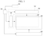
- FIG. 1 is a view schematically showing a stereoscopic display device according to an embodiment of the present disclosure
- FIG. 2 A is a view showing a cross-section of a display panel and a barrier panel of the stereoscopic display device according to the embodiment of the present disclosure
- FIG. 2 B is an enlarged view of region P in FIG. 2 A ;
- FIG. 2 C is an enlarged view of region R in FIG. 2 A ;
- FIG. 3 is a view showing a surface of the barrier panel of the stereoscopic display device according to the embodiment of the present disclosure
- FIGS. 4 A to 4 D and 5 A to 5 D are views showing a gradation change of the channels according to the viewing distance
- FIGS. 6 to 9 are views respectively showing a stereoscopic display device according to another embodiment of the present disclosure.
- first element when referred to as being “on” a second element, although the first element may be disposed on the second element so as to come into contact with the second element, a third element may be interposed between the first element and the second element.
- FIG. 1 is a view schematically showing a stereoscopic display device according to an embodiment of the present disclosure.
- FIG. 2 A is a view showing a cross-section of a display panel and a barrier panel of the stereoscopic display device according to the embodiment of the present disclosure.
- FIG. 2 B is an enlarged view of region P in FIG. 2 A .
- FIG. 2 C is an enlarged view of region R in FIG. 2 A .
- the stereoscopic display device may include a display panel 100 , a barrier panel 200 , a display driver 300 , a timing controller 400 , a viewing distance detector 500 and a barrier driver 600 .
- the display panel 100 may realize an image provided to the viewer.
- the display panel 100 may include a lower display substrate 110 , a light-emitting element 140 and an upper display substrate 180 , which are sequentially stacked.
- the display panel 100 may realize the image using the light generated by the light-emitting element 140 .
- the light-emitting element 140 may include a lower light-emitting electrode 141 , a light-emitting layer 142 and an upper light-emitting electrode 143 , which are sequentially stacked.
- the light-emitting layer 142 may include an organic light-emitting material or an inorganic light-emitting material.
- the display panel 100 of the stereoscopic display device according to the embodiment of the present disclosure may be an OLED panel including an organic light-emitting element.
- the display panel 100 may further include a thin film transistor 120 between the lower display substrate 110 and the light-emitting element 140 , an interlayer insulating layer 130 covering the thin film transistor 120 , and a bank insulating layer 150 covering an edge of the lower light-emitting electrode 141 .
- the light-emitting element 140 may be electrically connected to the interlayer insulating layer 130 .
- the lower light-emitting electrode 141 may be electrically connected to the thin film transistor 120 .
- the interlayer insulating layer 130 may include a contact hole for connecting the lower light-emitting electrode 141 to the thin film transistor 120 .
- the display panel 100 may further include an upper passivation layer 160 between the light-emitting element 140 and the upper display substrate 180 , and an adhesive layer 170 between the upper passivation layer 160 and the upper display substrate 180 .
- the upper display substrate 180 may be coupled to the lower display substrate in which the light-emitting element 140 is formed by the adhesive layer 170 .
- the upper passivation layer 160 and the adhesive layer 170 may prevent a damage of the light-emitting element 140 due to external impact.
- the adhesive layer 170 may include a lower adhesive layer 171 and an upper adhesive layer 172 .
- the upper adhesive layer 172 may be in direct contact with the lower adhesive layer 171 and the upper display substrate 180 .
- the adhesive layer 170 may prevent permeating the external moisture to the light-emitting element 140 .
- the upper adhesive layer 172 may include the moisture absorbing material 170 b.
- the barrier panel 200 may be disposed on the display panel 100 .
- the barrier panel 200 may separate the image realized by the display panel 100 , and provide it to the viewer's left eye and right eye.
- the image realized by the display panel 100 may be stereoscopically recognized to the viewer by the barrier panel 200 .
- the barrier panel 200 may selectively transmit or block the light.
- the barrier panel 200 may include a lower barrier substrate 201 , channels 202 , a liquid crystal layer 204 , a common electrode 205 and an upper barrier substrate 206 , which are sequentially stacked.
- the liquid crystal layer 204 may include TN mode or ECB mode liquid crystal.
- the channels 202 may have a multi-layer structure insulated by an insulating layer 203 .
- the stereoscopic display device may further comprise a front linear polarizer 710 disposed between the display panel 100 and the barrier panel 200 , and a rear linear polarizer 720 located on an outer surface of the barrier panel 200 .
- the rear linear polarizer 720 may include a transmission axis orthogonal with the front linear polarizer 710 .
- the rear linear polarizer 720 may be in direct contact with the barrier panel 200 .
- the barrier panel 200 may transmit or block the light according to the voltage applied to the channel 202 .
- the stereoscopic display device according to the embodiment of the present disclosure may be a normally white mode in which the liquid crystal layer 204 located on the voltage-applied channel 202 is driven to block the light.
- the barrier panel 200 may include barrier regions 210 and trigger regions 220 .
- the trigger regions 220 may be disposed between the barrier regions 210 .
- the trigger regions 220 may be located side-by-side with the barrier regions 210 .
- the trigger regions 220 may be disposed symmetrically with respect to the center of the barrier panel 200 .
- the barrier regions 210 and the trigger regions 220 may be extended in a vertical direction.
- a size of each trigger region 220 may be smaller than a size of each barrier region 210 .
- the trigger regions 220 may have the same size.
- the barrier regions 210 may have the same size. For example, a width W1 of each barrier region 210 may be larger than a width W2 of each trigger region 220 .
- the display driver 300 may drive the display panel 100 .
- the display panel 100 may receive signals for realizing the image from the display driver 300 .
- the display driver 300 may include a data driver 310 and a scan driver 320 .
- the data driver 310 may supply data signals to the display panel 100 .
- the scan driver 320 may sequentially apply scan signals to the display panel 100 .
- the data signals supplied by the data driver 310 may be synchronized with the scan signals applied by the scan driver 320 .
- the timing controller 400 may provide signal necessary for the operation of the display driver 300 .
- the timing controller 400 may provide a digital video data and a source timing controlling signal to the data driver 310 .
- the scan driver 320 may receive a clock signal, a reset clock signal and a start signal from the timing controller 400 .
- the viewing distance detector 500 may sense a viewing distance of a viewer.
- the viewing distance detector 500 may detect location information of the viewer viewing the image realized by the display panel 100 and the barrier panel 200 .
- the viewing distance detector 500 may include a camera.
- the camera may have a range finder circuit and sensor of a type known in the art to detect and determine the exact range of people's faces from the camera and thus also the distance from the display.
- the viewing distance detector 500 may work with a remote control that is controlling the program being viewed on the display. When the remote control is used to change the channel, the display can determine the exact distance between the remote control and display using known signal transmission technology.
- the user Since the user has just changed the program to a new program, In this example, the user will be expected to be holding the remote control and this will provide information of the distance the user is from the display. Other techniques might be used to determine the distance of the user, and in particular, the users face, from the display to determine the that distance.
- FIGS. 4 A to 4 D are views respectively showing a cross-section taken along I-I′ of FIG. 3 .
- each of FIGS. 4 A to 4 D shows a gradation change of the channels located within the barrier regions 210 and the trigger regions 220 of the barrier panel, when the viewer moves gradually closer to the display panel 100 from a region having a viewing distance of the proper range.
- the cross-section I-I′ is taken along just one side of the display and a corresponding change will be made in the barrier panel at a symmetrical location on the other side of the display, thus, a pair of grey areas will per present, one on each side of the barrier panel, even though only one side of the barrier is shown in FIGS. 4 A- 4 D and 5 A- 5 D .
- the barrier region 210 and the trigger regions 220 may have a transmitting region 211 and 221 , and a blocking region 212 and 222 , respectively.
- Each of the barrier regions 210 may include a barrier transmitting region 211 and a barrier blocking region 212 .
- the number of the channels within the barrier transmitting region 211 may be same as the number of the channels within the barrier blocking region 212 of the corresponding barrier region 210 .
- the barrier transmitting region 211 and the barrier blocking region 212 may have eight channels, respectively.
- Each of the barrier regions 210 may include 16 channels.
- each of barrier regions 210 may include the barrier transmitting region 211 located between the channels consisting of the barrier blocking region 212 and the barrier blocking region 212 located between the channels consisting of the barrier transmitting region 211 .
- each of the barrier regions 210 may include four channels for configuring the barrier blocking region 212 on both sides of the barrier transmitting region 211 , or four channels for configuring the barrier transmitting region 211 on both sides of the barrier blocking region 212 .
- the barrier regions 210 including the barrier transmitting region 211 between the channels consisting of the barrier blocking region 212 and the barrier regions 210 including the barrier blocking region 212 between the channels consisting of the barrier transmitting region 211 may be repeated.
- Each of the trigger regions 220 may include a trigger transmitting region 221 and a trigger blocking region 222 .
- the number of the channels within the trigger transmitting region 221 may be same as the number of the channel blocking region 222 of the corresponding trigger region 220 .
- the number of the channels within each trigger region 220 may be smaller than the number of the channels within each barrier region 210 .
- the number of the channels within the trigger region 220 may be a half of the number of the channels within the barrier region 210 .
- the trigger transmitting region 221 and the trigger blocking region 222 may have four channels, respectively.
- the trigger transmitting region 221 of each trigger region 220 may be in direct contact with the barrier transmitting region 211 of adjacent barrier region 210 .
- the gray value of the trigger transmitting region 221 may be same as the gray value of the barrier transmitting region 211 .
- the barrier transmitting region 211 and the trigger transmitting region 221 adjacent to the barrier transmitting region 211 may consist of the transmitting region 211 and 221 of the barrier panel 200 .
- the trigger blocking region 222 of each trigger region 220 may be in direct contact with the barrier blocking region 212 of adjacent barrier region 210 .
- the gray value of the trigger blocking region 222 may be same as the gray value of the barrier blocking region 212 .
- the trigger blocking region 222 and the barrier blocking region 212 adjacent to the trigger blocking region 222 may consist of the blocking region 212 and 222 of the barrier panel 200 .
- transmitting regions 211 and 221 , and blocking regions 212 and 222 are regularly repeated, when the viewer is located within a region having the viewing distance of the proper range.
- the trigger region 220 farthest from the center of the barrier panel 200 may include a channel 223 having intermediate gray value, as shown in FIG. 4 B .
- the number of the channels consisting of the trigger blocking region 222 may be smaller than the number of the channels consisting of the trigger transmitting region 221 .
- the trigger region 220 farthest from the center of the barrier panel 200 may include the trigger transmitting region 221 having three channels and the trigger blocking region 222 having four channels.
- the transmitting region 211 and 221 farthest the center of the barrier panel may move toward the outside of the barrier panel, when the location of the viewer is closer than the region having the viewing distance of the proper range.
- the transmitting region 211 and 221 of the barrier panel moves toward the outside of the barrier panel, the focus of the stereoscopic image provided to the viewer may be brought closer to the display panel. Therefore, in the stereoscopic display device according to the embodiment of the present disclosure, the transmitting region 211 and 221 of the barrier panel may move toward the outside of the barrier panel by locating some channel 223 having the intermediate gray value within the trigger region 220 , so that the stereoscopic image of good quality may provide to the viewer being a first close distance that is closer than the region having the viewing distance of the proper range.
- the channel 223 having the intermediate gray value is disposed between the trigger transmitting region 221 and the trigger blocking region 222 in the corresponding trigger region 220 .
- a boundary between the trigger transmitting region 221 and the trigger blocking region 222 having different numbers of the channels for example a boundary between the trigger transmitting region 221 having three channels and the trigger blocking region 222 having four channels, may be blurredly recognized to the viewer.
- the change size of the transmitting region 211 and 221 , or the blocking region 212 and 222 which are located adjacent, is recognized by the viewer closer than the region having the viewing distance of the proper range as a bright line or a dark line.
- the stereoscopic display device only describes the trigger region 220 near the one side of the barrier panel.
- the trigger regions 220 positioned to be symmetrical with respect to the center of the barrier panel may be controlled in the same manner, substantially.
- a pair of trigger regions 220 farthest from the center of the barrier panel may respectively include the channel 223 having the intermediate gray value, so that a pair of transmitting regions 211 and 221 farthest from the center of the barrier panel may move toward the corresponding outside of the barrier panel.
- the trigger region 220 farthest from the center of the barrier panel and the trigger region 220 secondly far from the center of the barrier panel may include a channel 223 having the intermediate gray value, as shown in FIG. 4 C .
- the barrier transmitting region 211 of the barrier region 210 between two the trigger regions 220 including the channel 223 having the intermediate gray value may move toward the outside of the barrier panel. That is, the barrier region 220 between two trigger regions 220 including the channel 223 having the intermediate gray value, may include the barrier transmitting region 221 having eight channels between the barrier blocking region 212 having three channels and the barrier blocking region 212 having five channels.
- the transmitting region 211 and 221 farthest from the center of the barrier panel may move further the outside of the barrier panel.
- the focus of the stereoscopic image may be further brought closer to the display panel.
- the trigger region 220 farthest from the center of the barrier panel, the trigger region 220 secondly far from the center of the barrier panel, and the trigger region 220 third far from the center of the barrier panel may include a channel 223 having the intermediate gray value.
- the focus of the stereoscopic image may be brought even closer to the display panel by further moving the transmitting region 211 and 221 farthest from the center of the barrier panel toward the outside of the barrier panel.
- FIGS. 5 A to 5 D are views respectively showing a cross-section taken along I-I′ of FIG. 3 . Also, each of FIGS. 5 A to 5 D shows a gradation change of the channels located within the barrier regions 210 and the trigger regions 220 of the barrier panel, when the viewer is gradually moving away from the region having the viewing distance of the proper range.
- the barrier panel may include transmitting regions 211 and 221 , and blocking regions 212 and 222 , as shown in FIG. 5 A .
- the trigger region 220 farthest from the center of the barrier panel may include the channel 223 having the intermediate gray value
- the number of the channels consisting of the trigger transmitting region 221 may be larger than the number of the channels consisting of the trigger blocking region 222 .
- the trigger region 220 farthest from the center of the barrier panel may include the trigger transmitting region 221 having four channels and the trigger blocking region 222 having three channels.
- the transmitting region 211 and 221 farthest from the center of the barrier panel may move toward the center of the barrier panel, when the viewer moves away from the region having the viewing distance of the proper range.
- the transmitting regions 211 and 221 of the barrier panel may move toward the center of the barrier panel by locating the channel 223 having the intermediate gray value within the trigger region 220 , so that the stereoscopic image of good quality may provide to the viewer moving away from the region having the viewing distance of the proper range.
- the trigger region 220 farthest from the center of the barrier panel and the trigger region 220 secondly far from the center of the barrier panel may include the channel 223 having the intermediate gray value.
- the trigger region 220 farthest from the center of the barrier panel, and the barrier transmitting region 211 of the barrier panel 210 disposed between two trigger region 220 including the channel 223 having the intermediate gray value may move toward the center of the barrier panel. Therefore, in the stereoscopic display device according to the embodiment of the present disclosure, the focus of the stereoscopic image may further move away from the display panel.
- the trigger region 220 farthest from the center of the barrier panel, the trigger region 220 secondly far from the center of the barrier panel and the trigger region 220 third far from the center of the barrier panel may include the channel 223 having the intermediate gray value.
- the focus of the stereoscopic image may further mover away from the display panel by further moving the transmitting regions 211 and 221 of the barrier panel toward the center of the barrier panel.
- the channel 223 having the intermediate gray value is preferentially located within the trigger region 220 farthest from the center of the barrier panel, when the location of the viewer is out of the region having the viewing distance of the proper range.
- the trigger region 220 closest to the center of the barrier panel includes preferentially the channel 223 having the intermediate gray value, so that a stereoscopic image of good quality is provided to the viewer located at a region being out of the proper range.
- a pair of the trigger regions 220 symmetrical with respect to the center of the barrier panel may include the channel 223 having the intermediate gray value according to the location of the viewer located at the region being out of the proper range, so that the size ratio between the trigger transmitting region 221 and the trigger blocking region 222 of the corresponding trigger region 220 may be adjusted, and the transmitting region 211 and 221 of the barrier panel may be moved.
- the stereoscopic image of good quality may be provided to the viewer located at the region being out of the proper range.
- the channel 223 having the intermediate gray value may be disposed between the trigger transmitting region 221 and the trigger blocking region 222 of the corresponding trigger region 220 , so that the signal applied to the channel having the intermediate gray value may not affect the channels within the barrier transmitting region 211 and the barrier blocking region 212 of adjacent barrier region 210 .
- the stereoscopic image of good quality may be provided to the viewer located at the region being out of the proper range without affecting the gradation of the channel within the barrier region 210 .
- the stereoscopic display device according to the embodiment of the present disclosure may further comprise a structure for preventing reflection of external light.
- the stereoscopic display device according to the embodiment of the present disclosure may further include a quarter-wave plate 800 between the display panel 100 and the front linear polarizer 710 , as shown in FIG. 2 A .
- the quarter-wave plate 800 may be in direct contact with the display panel 100 and the front linear polarizer 710 .
- the stereoscopic display device is described that the width of the trigger regions 220 is a half of the width of the barrier regions 210 .
- the stereoscopic display device may include the barrier panel 200 in which the width of the barrier regions 210 is at least twice the width of the trigger regions 220 , as shown in FIG. 6 .
- the trigger regions 220 having eight channels may be disposed between the barrier regions 210 having at least 17 channels.
- the focus of the stereoscopic image provided to the viewer may be finely adjusted according to the distance between the location of the viewer and the region being out of the proper range.
- the stereoscopic display device is described that the barrier regions 210 have the same width. However, in the stereoscopic display device according to another embodiment of the present disclosure, the width of the barrier regions 210 may be reduced toward the outside of the barrier panel 200 , as shown in FIG. 7 . Thus, in the stereoscopic display device according to another embodiment of the present disclosure, the focus of the stereoscopic image provided to the viewer may be efficiently adjusted according to the location variation of the viewer.
- the stereoscopic display device is described that the barrier panel 200 is located on the display panel 100 including the light-emitting element 140 .
- the stereoscopic display device may include the barrier panel 200 between the display panel 100 and the light-emitting element 900 , as shown in FIG. 8 .
- the display panel 100 of the stereoscopic display device may be the liquid crystal panel.
- the light-emitting element 900 may serve as a back-light unit.
- the front linear polarizer 710 and the rear linear polarizer 720 may be in direct contact with the barrier panel 200 .
- An image linear polarizer 730 may be disposed on the outer surface of the display panel 100 .
- the stereoscopic image of good quality may be provided to the viewer located at the region being out of the proper range without the relative location of the display panel 100 and the barrier panel 200 .
- the stereoscopic display device is described that the barrier panel 200 is located between the light-emitting element 900 and the display panel 100 .
- the stereoscopic display device may include the display panel 100 between the light-emitting element 900 and the barrier panel 200 , as shown in FIG. 9 .
- An image linear polarizer 740 may be disposed between the light-emitting element 900 and the display panel 100 .
- the image linear polarizer 730 and the front linear polarizer 710 may be in direct contact with the display panel 100 .
- the stereoscopic image of good quality may be provided to the viewer located at the region being out of the proper range in the display panel 100 and the barrier panel 200 at various positions.
- the stereoscopic display device may prevent the generation of bright line and dark line due to the blocking regions and the transmitting regions of the barrier panel which are moved according to the viewing distance change by using the channels within the trigger regions.
- the stereoscopic image of good quality may be provided to the viewer located at the region being out of the proper range.
- the region viewing the stereoscopic image may be increased without degrading the quality of the stereoscopic image.
Abstract
Description
Claims (20)
Priority Applications (1)
| Application Number | Priority Date | Filing Date | Title |
|---|---|---|---|
| US16/839,944 US11924399B2 (en) | 2017-04-18 | 2020-04-03 | Stereoscopic display device having a barrier panel |
Applications Claiming Priority (4)
| Application Number | Priority Date | Filing Date | Title |
|---|---|---|---|
| KR1020170050033A KR101888449B1 (en) | 2017-04-18 | 2017-04-18 | Stereoscopic Display device having a barrier panel |
| KR10-2017-0050033 | 2017-04-18 | ||
| US15/955,507 US10656430B2 (en) | 2017-04-18 | 2018-04-17 | Stereoscopic display device having a barrier panel |
| US16/839,944 US11924399B2 (en) | 2017-04-18 | 2020-04-03 | Stereoscopic display device having a barrier panel |
Related Parent Applications (1)
| Application Number | Title | Priority Date | Filing Date |
|---|---|---|---|
| US15/955,507 Continuation US10656430B2 (en) | 2017-04-18 | 2018-04-17 | Stereoscopic display device having a barrier panel |
Publications (2)
| Publication Number | Publication Date |
|---|---|
| US20200233231A1 US20200233231A1 (en) | 2020-07-23 |
| US11924399B2 true US11924399B2 (en) | 2024-03-05 |
Family
ID=63443576
Family Applications (2)
| Application Number | Title | Priority Date | Filing Date |
|---|---|---|---|
| US15/955,507 Active 2038-06-22 US10656430B2 (en) | 2017-04-18 | 2018-04-17 | Stereoscopic display device having a barrier panel |
| US16/839,944 Active 2038-09-28 US11924399B2 (en) | 2017-04-18 | 2020-04-03 | Stereoscopic display device having a barrier panel |
Family Applications Before (1)
| Application Number | Title | Priority Date | Filing Date |
|---|---|---|---|
| US15/955,507 Active 2038-06-22 US10656430B2 (en) | 2017-04-18 | 2018-04-17 | Stereoscopic display device having a barrier panel |
Country Status (3)
| Country | Link |
|---|---|
| US (2) | US10656430B2 (en) |
| KR (1) | KR101888449B1 (en) |
| CN (1) | CN108732774B (en) |
Families Citing this family (2)
| Publication number | Priority date | Publication date | Assignee | Title |
|---|---|---|---|---|
| KR101888449B1 (en) * | 2017-04-18 | 2018-08-16 | 엘지디스플레이 주식회사 | Stereoscopic Display device having a barrier panel |
| KR102056677B1 (en) * | 2017-09-07 | 2019-12-17 | 엘지디스플레이 주식회사 | Stereoscopic Display device having a barrier panel |
Citations (8)
| Publication number | Priority date | Publication date | Assignee | Title |
|---|---|---|---|---|
| US20110051239A1 (en) * | 2009-08-31 | 2011-03-03 | Casio Computer Co., Ltd. | Three dimensional display device and method of controlling parallax barrier |
| CN103135280A (en) | 2012-11-15 | 2013-06-05 | 中航华东光电有限公司 | Liquid crystal barrier grid stereo display system |
| KR20150026029A (en) | 2013-08-30 | 2015-03-11 | 엘지디스플레이 주식회사 | 3-dimension image display device and driving method thereof |
| WO2017010104A1 (en) | 2015-07-14 | 2017-01-19 | Sharp Kabushiki Kaisha | Parallax barrier with independently controllable regions |
| US20170133444A1 (en) | 2015-11-11 | 2017-05-11 | Samsung Display Co., Ltd. | Organic light emitting display device |
| US9706192B2 (en) * | 2011-06-20 | 2017-07-11 | Panasonic Intellectual Property Corporation Of America | Image display device and image display method |
| US10257504B2 (en) * | 2016-02-04 | 2019-04-09 | Japan Display Inc. | Display device |
| US10656430B2 (en) * | 2017-04-18 | 2020-05-19 | Lg Display Co., Ltd. | Stereoscopic display device having a barrier panel |
-
2017
- 2017-04-18 KR KR1020170050033A patent/KR101888449B1/en active IP Right Grant
-
2018
- 2018-04-17 CN CN201810342394.7A patent/CN108732774B/en active Active
- 2018-04-17 US US15/955,507 patent/US10656430B2/en active Active
-
2020
- 2020-04-03 US US16/839,944 patent/US11924399B2/en active Active
Patent Citations (10)
| Publication number | Priority date | Publication date | Assignee | Title |
|---|---|---|---|---|
| US20110051239A1 (en) * | 2009-08-31 | 2011-03-03 | Casio Computer Co., Ltd. | Three dimensional display device and method of controlling parallax barrier |
| US8817369B2 (en) | 2009-08-31 | 2014-08-26 | Samsung Display Co., Ltd. | Three dimensional display device and method of controlling parallax barrier |
| US9706192B2 (en) * | 2011-06-20 | 2017-07-11 | Panasonic Intellectual Property Corporation Of America | Image display device and image display method |
| CN103135280A (en) | 2012-11-15 | 2013-06-05 | 中航华东光电有限公司 | Liquid crystal barrier grid stereo display system |
| KR20150026029A (en) | 2013-08-30 | 2015-03-11 | 엘지디스플레이 주식회사 | 3-dimension image display device and driving method thereof |
| WO2017010104A1 (en) | 2015-07-14 | 2017-01-19 | Sharp Kabushiki Kaisha | Parallax barrier with independently controllable regions |
| US20180205942A1 (en) | 2015-07-14 | 2018-07-19 | Sharp Kabushiki Kaisha | Parallax barrier with independently controllable regions |
| US20170133444A1 (en) | 2015-11-11 | 2017-05-11 | Samsung Display Co., Ltd. | Organic light emitting display device |
| US10257504B2 (en) * | 2016-02-04 | 2019-04-09 | Japan Display Inc. | Display device |
| US10656430B2 (en) * | 2017-04-18 | 2020-05-19 | Lg Display Co., Ltd. | Stereoscopic display device having a barrier panel |
Also Published As
| Publication number | Publication date |
|---|---|
| CN108732774A (en) | 2018-11-02 |
| US10656430B2 (en) | 2020-05-19 |
| CN108732774B (en) | 2020-12-15 |
| KR101888449B1 (en) | 2018-08-16 |
| US20180299685A1 (en) | 2018-10-18 |
| US20200233231A1 (en) | 2020-07-23 |
Similar Documents
| Publication | Publication Date | Title |
|---|---|---|
| US9274356B2 (en) | Parallax barrier type stereoscopic image display device | |
| US8264626B2 (en) | Stereoscopic image display device | |
| US8665383B2 (en) | Mother substrate for stereoscopic image display device | |
| US20110102689A1 (en) | 2d and 3d switchable display device and liquid crystal lens thereof | |
| US11924399B2 (en) | Stereoscopic display device having a barrier panel | |
| US8766878B2 (en) | Integral photography type three-dimensional display device | |
| US20160274373A1 (en) | Display device and method for controlling the same | |
| US10816819B1 (en) | Stereoscopic display device having a barrier panel | |
| US11150487B2 (en) | Stereoscopic display device having a barrier panel | |
| US11061247B2 (en) | Liquid crystal parallax barrier and method of addressing | |
| CN109991755B (en) | Transparent display device | |
| JP2009150956A (en) | Electrical engineering device | |
| US10838223B2 (en) | Stereoscopic display device having a barrier panel | |
| US20190208185A1 (en) | Stereoscopic display device having a barrier panel | |
| KR102648978B1 (en) | Stereoscopic Display apparatus having a light source unit and a display panel | |
| KR20180117006A (en) | Stereoscopic Display device having a barrier panel | |
| KR101974381B1 (en) | Display panel and display apparatus including the same | |
| KR20200077849A (en) | Volumetric image display device realizing a stereoscopic image by stacking images |
Legal Events
| Date | Code | Title | Description |
|---|---|---|---|
| FEPP | Fee payment procedure |
Free format text: ENTITY STATUS SET TO UNDISCOUNTED (ORIGINAL EVENT CODE: BIG.); ENTITY STATUS OF PATENT OWNER: LARGE ENTITY |
|
| STPP | Information on status: patent application and granting procedure in general |
Free format text: APPLICATION DISPATCHED FROM PREEXAM, NOT YET DOCKETED |
|
| STPP | Information on status: patent application and granting procedure in general |
Free format text: DOCKETED NEW CASE - READY FOR EXAMINATION |
|
| STPP | Information on status: patent application and granting procedure in general |
Free format text: NON FINAL ACTION MAILED |
|
| STPP | Information on status: patent application and granting procedure in general |
Free format text: RESPONSE TO NON-FINAL OFFICE ACTION ENTERED AND FORWARDED TO EXAMINER |
|
| STPP | Information on status: patent application and granting procedure in general |
Free format text: FINAL REJECTION MAILED |
|
| STPP | Information on status: patent application and granting procedure in general |
Free format text: DOCKETED NEW CASE - READY FOR EXAMINATION |
|
| STPP | Information on status: patent application and granting procedure in general |
Free format text: NON FINAL ACTION MAILED |
|
| STPP | Information on status: patent application and granting procedure in general |
Free format text: NON FINAL ACTION MAILED |
|
| STPP | Information on status: patent application and granting procedure in general |
Free format text: NOTICE OF ALLOWANCE MAILED -- APPLICATION RECEIVED IN OFFICE OF PUBLICATIONS |
|
| STPP | Information on status: patent application and granting procedure in general |
Free format text: NOTICE OF ALLOWANCE MAILED -- APPLICATION RECEIVED IN OFFICE OF PUBLICATIONS |
|
| STPP | Information on status: patent application and granting procedure in general |
Free format text: PUBLICATIONS -- ISSUE FEE PAYMENT VERIFIED |
|
| STCF | Information on status: patent grant |
Free format text: PATENTED CASE |