US11923929B2 - Channel information obtaining method - Google Patents
Channel information obtaining method Download PDFInfo
- Publication number
- US11923929B2 US11923929B2 US17/741,143 US202217741143A US11923929B2 US 11923929 B2 US11923929 B2 US 11923929B2 US 202217741143 A US202217741143 A US 202217741143A US 11923929 B2 US11923929 B2 US 11923929B2
- Authority
- US
- United States
- Prior art keywords
- network device
- terminal device
- precoding matrix
- channel vector
- channel
- Prior art date
- Legal status (The legal status is an assumption and is not a legal conclusion. Google has not performed a legal analysis and makes no representation as to the accuracy of the status listed.)
- Active, expires
Links
- 238000000034 method Methods 0.000 title claims abstract description 236
- 238000004891 communication Methods 0.000 claims abstract description 121
- 239000011159 matrix material Substances 0.000 claims description 275
- 230000008569 process Effects 0.000 claims description 48
- 238000009826 distribution Methods 0.000 claims description 22
- 230000015654 memory Effects 0.000 description 68
- 238000012545 processing Methods 0.000 description 66
- 230000006870 function Effects 0.000 description 44
- 230000005540 biological transmission Effects 0.000 description 37
- 238000005457 optimization Methods 0.000 description 23
- 230000000875 corresponding effect Effects 0.000 description 22
- 238000010586 diagram Methods 0.000 description 17
- 238000004590 computer program Methods 0.000 description 16
- 238000003860 storage Methods 0.000 description 13
- 230000009471 action Effects 0.000 description 11
- 238000001228 spectrum Methods 0.000 description 10
- 230000006835 compression Effects 0.000 description 8
- 238000007906 compression Methods 0.000 description 8
- 238000005516 engineering process Methods 0.000 description 7
- 230000011664 signaling Effects 0.000 description 7
- 238000000605 extraction Methods 0.000 description 6
- 238000013461 design Methods 0.000 description 5
- 230000001360 synchronised effect Effects 0.000 description 4
- 238000013528 artificial neural network Methods 0.000 description 3
- 230000008878 coupling Effects 0.000 description 3
- 238000010168 coupling process Methods 0.000 description 3
- 238000005859 coupling reaction Methods 0.000 description 3
- 238000010295 mobile communication Methods 0.000 description 3
- 230000003044 adaptive effect Effects 0.000 description 2
- 238000013473 artificial intelligence Methods 0.000 description 2
- 238000012937 correction Methods 0.000 description 2
- 230000000977 initiatory effect Effects 0.000 description 2
- 230000007774 longterm Effects 0.000 description 2
- 230000003287 optical effect Effects 0.000 description 2
- 239000004065 semiconductor Substances 0.000 description 2
- 238000004088 simulation Methods 0.000 description 2
- 239000007787 solid Substances 0.000 description 2
- 230000003068 static effect Effects 0.000 description 2
- NAWXUBYGYWOOIX-SFHVURJKSA-N (2s)-2-[[4-[2-(2,4-diaminoquinazolin-6-yl)ethyl]benzoyl]amino]-4-methylidenepentanedioic acid Chemical compound C1=CC2=NC(N)=NC(N)=C2C=C1CCC1=CC=C(C(=O)N[C@@H](CC(=C)C(O)=O)C(O)=O)C=C1 NAWXUBYGYWOOIX-SFHVURJKSA-N 0.000 description 1
- 230000001413 cellular effect Effects 0.000 description 1
- 238000006243 chemical reaction Methods 0.000 description 1
- 239000003795 chemical substances by application Substances 0.000 description 1
- 230000008602 contraction Effects 0.000 description 1
- 230000002596 correlated effect Effects 0.000 description 1
- 238000013500 data storage Methods 0.000 description 1
- 230000004069 differentiation Effects 0.000 description 1
- 230000003993 interaction Effects 0.000 description 1
- 238000012804 iterative process Methods 0.000 description 1
- 238000013507 mapping Methods 0.000 description 1
- 239000013307 optical fiber Substances 0.000 description 1
- 230000009467 reduction Effects 0.000 description 1
- 238000005070 sampling Methods 0.000 description 1
- 230000007480 spreading Effects 0.000 description 1
- 238000003892 spreading Methods 0.000 description 1
- 238000012546 transfer Methods 0.000 description 1
Images


Classifications
-
- H—ELECTRICITY
- H04—ELECTRIC COMMUNICATION TECHNIQUE
- H04B—TRANSMISSION
- H04B7/00—Radio transmission systems, i.e. using radiation field
- H04B7/02—Diversity systems; Multi-antenna system, i.e. transmission or reception using multiple antennas
- H04B7/04—Diversity systems; Multi-antenna system, i.e. transmission or reception using multiple antennas using two or more spaced independent antennas
- H04B7/0413—MIMO systems
- H04B7/0456—Selection of precoding matrices or codebooks, e.g. using matrices antenna weighting
-
- H—ELECTRICITY
- H04—ELECTRIC COMMUNICATION TECHNIQUE
- H04B—TRANSMISSION
- H04B7/00—Radio transmission systems, i.e. using radiation field
- H04B7/02—Diversity systems; Multi-antenna system, i.e. transmission or reception using multiple antennas
- H04B7/04—Diversity systems; Multi-antenna system, i.e. transmission or reception using multiple antennas using two or more spaced independent antennas
- H04B7/04013—Intelligent reflective surfaces
-
- H—ELECTRICITY
- H04—ELECTRIC COMMUNICATION TECHNIQUE
- H04L—TRANSMISSION OF DIGITAL INFORMATION, e.g. TELEGRAPHIC COMMUNICATION
- H04L5/00—Arrangements affording multiple use of the transmission path
- H04L5/003—Arrangements for allocating sub-channels of the transmission path
- H04L5/0048—Allocation of pilot signals, i.e. of signals known to the receiver
Definitions
- This application relates to the communications field, and more specifically, to a channel information obtaining method.
- a new MIMO system may be formed by adding another network device to an existing multiple input multiple output (multiple input multiple output, MIMO) system.
- the MIMO system needs to know complete channel information.
- Frequency division duplex (frequency division duplex, FDD) downlink transmission is used as an example.
- FDD frequency division duplex
- the MIMO system to which the another network device is added needs to separately know information about a channel between the first network device and a terminal device and information about a channel between the first network device, the second network device, and the terminal device. Because there are hundreds of thousands of array elements in the second network device, the channel between the first network device, the second network device, and the terminal device is usually of a large dimension. Therefore, a method with low pilot overheads, a low delay, and high precision is urgently required to obtain the information about the channel between the first network device, the second network device, and the terminal device.
- This application provides a channel information obtaining method, to reduce pilot overheads and a delay in a process of obtaining information about a channel between a first network device, a second network device, and a terminal device.
- a channel information obtaining method includes: A terminal device receives one or more first reference signals on a d th port of the terminal device, where the first reference signal is a reference signal from a first network device, d ⁇ [1, D], D is a quantity of ports of the terminal device, and D is a positive integer.
- the terminal device obtains a first channel vector h 1,d based on the received first reference signal, where h 1,d is a channel vector of a channel between the d th port of the terminal device and the first network device.
- the terminal device receives N second reference signals on the d th port of the terminal device, where N is a quantity of ports of the second reference signal, and N is an integer greater than or equal to 2.
- the terminal device obtains a second channel vector h 2,d based on the received second reference signal.
- the terminal device calculates a third channel vector h 3,d based on h 1,d and h 2,d , where a quantity of ports of h 3,d is less than a quantity of ports of a fourth channel vector h 4,d , and h 4,d is a channel vector of a channel between the first network device, a second network device, and the d th port of the terminal device.
- the terminal device calculates h 4,d based on h 3,d .
- the quantity of ports of the third channel vector obtained by the terminal device based on the received second reference signal is less than the quantity of ports of the fourth channel vector.
- the terminal device may calculate the fourth channel vector based on the third channel vector by using a compressed sensing algorithm or an artificial intelligence algorithm, to reduce pilot overheads and a delay of obtaining the fourth channel vector.
- each second reference signal includes a first component and a second component
- the first precoding matrix and the second precoding matrix are used to process h 4,d to obtain h 3,d .
- the third channel vector whose quantity of ports is less than the quantity of ports of the fourth channel vector may be obtained.
- the method further includes: The terminal device calculates the first precoding matrix and the second precoding matrix.
- the terminal device sends the first precoding matrix and the second precoding matrix to the first network device.
- the method further includes: The terminal device receives the first precoding matrix and the second precoding matrix.
- the first precoding matrix and the second precoding matrix are specified in a communications protocol.
- the method further includes: The terminal device obtains a third precoding matrix w and a fourth precoding matrix ⁇ based on h 1,d and h 4,d , where w is a precoding matrix used when the first network device transmits data to the terminal device, and ⁇ is a precoding matrix used when the second network device transmits data to the terminal device.
- the terminal device sends w and ⁇ to the first network device.
- that the terminal device obtains a third precoding matrix w and a fourth precoding matrix ⁇ based on h 1,d and h 4,d includes: The terminal device iterates the following two processes by using a first indicator as an optimization target until the optimization target is no longer added: (1) fixing w and calculating ⁇ ; and (2) fixing ⁇ and calculating w , where the first indicator includes one or more of the following: spectrum efficiency, energy efficiency, a transmission rate, and an error between the first indicator and a target transmission solution.
- w is
- the method further includes: The terminal device sends h 1,d and h 4,d to the first network device.
- the N second reference signals are sent in a time division multiplexing manner.
- a channel information obtaining method includes: A second network device receives N third reference signals from a first network device, where N is a quantity of ports of the third reference signal, and N is an integer greater than or equal to 2.
- the second precoding matrix is used to process a fourth channel vector h 4,d to obtain a third channel vector h 3,d , a quantity of ports of h 3,d is less than a quantity of ports of h 4,d , h 4,d is a channel vector of a channel between the first network device, the second network device, and a d th port of a terminal device, d ⁇ [1, D], D is a quantity of ports of the terminal device, and D is a positive integer.
- the second network device sends the N fourth reference signals to the terminal device.
- the second network device processes the fourth channel vector by using the second precoding matrix.
- the quantity of ports of the obtained third channel vector is less than the quantity of ports of the fourth channel vector.
- the fourth channel vector may be calculated based on the third channel vector, to reduce pilot overheads and a delay of obtaining the fourth channel vector.
- the method before that the second network device generates N fourth reference signals, the method further includes: The second network device receives the second precoding matrix from the first network device.
- the second precoding matrix is specified in a communications protocol.
- the method further includes: The second network device receives a fourth precoding matrix ⁇ from the first network device, where ⁇ is a precoding matrix used when the second network device transmits data to the terminal device.
- that the second network device sends the N fourth reference signals to the terminal device includes: The second network device sends the N fourth reference signals to the terminal device in a time division multiplexing manner.
- a channel information obtaining method includes: A first network device sends one or more first reference signals, where the first reference signal is used to calculate a first channel vector h 1,d , h 1,d is a channel vector of a channel between a d th port of a terminal device and the first network device, d ⁇ [1, D], D is a quantity of ports of the terminal device, and D is a positive integer.
- the first network device sends different references to the terminal device. Therefore, the terminal device may obtain different channel information based on the received different reference signals.
- the first network device sends the first precoding matrix and the second precoding matrix to the terminal device.
- the first network device sends the second precoding matrix to the second network device.
- the first network device processes a fourth channel vector by using the first precoding matrix
- the second network device processes the fourth channel vector by using the second precoding matrix.
- a quantity of ports of an obtained third channel vector is less than a quantity of ports of the fourth channel vector.
- the fourth channel vector may be calculated based on the third channel vector, to reduce pilot overheads and a delay of obtaining the fourth channel vector.
- the first precoding matrix is specified in a communications protocol.
- the method further includes: The first network device receives h 1,d and h 4,d from the terminal device.
- the method further includes: The first network device obtains a third precoding matrix w and a fourth precoding matrix ⁇ based on h 1,d and h 4,d , where w is a precoding matrix used when the first network device transmits data to the terminal device, and ⁇ is a precoding matrix used when the second network device transmits data to the terminal device.
- the first network device sends ⁇ to the second network device.
- the first network device calculates the third precoding matrix w and the fourth precoding matrix ⁇ based on received h 1,d and h 4,d . Because the first network device has channel information of all terminal devices, multi-user interference can be effectively eliminated.
- the first network device obtains a third precoding matrix w and a fourth precoding matrix ⁇ based on h 1,d and h 4,d includes: The first network device iterates the following two processes by using a first indicator as an optimization target until the optimization target is no longer added: (1) fixing w and calculating ⁇ ; and (2) fixing ⁇ and calculating w , where the first indicator includes one or more of the following: spectrum efficiency, energy efficiency, a transmission rate, and an error between the first indicator and a target transmission solution.
- w is
- a channel information obtaining apparatus includes a transceiver unit and a processing unit.
- the transceiver unit is configured to receive one or more first reference signals, where the first reference signal is a reference signal from a first network device.
- the processing unit is configured to obtain a first channel vector h 1,d based on the received first reference signal, where h 1,d is a channel vector of a channel between a d th port of the apparatus and the first network device, d ⁇ [1, D], D is a quantity of ports of the apparatus, and D is a positive integer.
- the transceiver unit is further configured to receive N second reference signals, where N is a quantity of ports of the second reference signal, and N is an integer greater than or equal to 2.
- the processing unit is further configured to obtain a second channel vector h 2,d based on the received second reference signal.
- the processing unit is further configured to calculate a third channel vector h 3,d based on h 1,d and h 2,d , where a quantity of ports of h 3,d is less than a quantity of ports of a fourth channel vector h 4,d , and h 4,d is a channel vector of a channel between the first network device, a second network device, and the d th port of the apparatus.
- the processing unit is further configured to calculate h 4,d based on h 3,d .
- each second reference signal includes a first component and a second component
- the first precoding matrix and the second precoding matrix are used to process h 4,d to obtain h 3,d .
- ⁇ is represented as ⁇ [w 1 T ⁇ 1 T , w 2 T ⁇ 2 T , . . . , w N T ⁇ N T ] T .
- the processing unit is further configured to calculate the first precoding matrix and the second precoding matrix.
- the transceiver unit is further configured to send the first precoding matrix and the second precoding matrix to the first network device.
- the transceiver unit is further configured to receive the first precoding matrix and the second precoding matrix.
- the first precoding matrix and the second precoding matrix are specified in a communications protocol.
- the processing unit is further configured to obtain a third precoding matrix w and a fourth precoding matrix ⁇ based on h 1,d and h 4,d , where w is a precoding matrix used when the first network device transmits data to the apparatus, and ⁇ is a precoding matrix used when the second network device transmits data to the apparatus.
- the transceiver unit is further configured to send w and ⁇ to the first network device.
- the processing unit is further configured to obtain a third precoding matrix w and a fourth precoding matrix ⁇ based on h 1,d and h 4,d includes: The processing unit iterates the following two processes by using a first indicator as an optimization target until the optimization target is no longer added: (1) fixing w and calculating ⁇ ; and (2) fixing ⁇ and calculating w , where the first indicator includes one or more of the following: spectrum efficiency, energy efficiency, a transmission rate, and an error between the first indicator and a target transmission solution.
- w is
- the transceiver unit is further configured to send h 1,d and h 4,d to the first network device.
- the N second reference signals are sent in a time division multiplexing manner.
- a channel information obtaining apparatus includes a processing unit and a transceiver unit.
- the transceiver unit is configured to receive N third reference signals from a first network device, where N is a quantity of ports of the third reference signal, and N is an integer greater than or equal to 2.
- the second precoding matrix is used to process a fourth channel vector h 4,d to obtain a third channel vector h 3,d , a quantity of ports of h 3,d is less than a quantity of ports of h 4,d , h 4,d is a channel vector of a channel between the first network device, the apparatus, and a d th port of a terminal device, d ⁇ [1, D], D is a quantity of ports of the terminal device, and D is a positive integer.
- the transceiver unit is further configured to send the N fourth reference signals to the terminal device.
- the transceiver unit before that the processing unit generates the N fourth reference signals, the transceiver unit is further configured to receive the second precoding matrix from the first network device.
- the second precoding matrix is specified in a communications protocol.
- the transceiver unit is further configured to receive a fourth precoding matrix ⁇ from the first network device, where ⁇ is a precoding matrix used when the apparatus transmits data to the terminal device.
- transceiver unit sends the N fourth reference signals to the terminal device includes: The transceiver unit sends the N fourth reference signals to the terminal device in a time division multiplexing manner.
- a channel information obtaining apparatus includes a transceiver unit and a processing unit.
- the transceiver unit is further configured to send one or more first reference signals, where the first reference signal is used to calculate a first channel vector h 1,d , h 1,d is a channel vector of a channel between a d th port of a terminal device and the apparatus, d ⁇ [1, D], D is a quantity of ports of the terminal device, and D is a positive integer.
- the transceiver unit is further configured to send the second precoding matrix to the second network device.
- the transceiver unit is further configured to send the first precoding matrix and the second precoding matrix to the terminal device.
- the transceiver unit is further configured to send the second precoding matrix to the second network device.
- the first precoding matrix is specified in a communications protocol.
- the transceiver unit is further configured to receive h 1,d and h 4,d from the terminal device.
- the processing unit obtains a third precoding matrix w and a fourth precoding matrix ⁇ based on h 1,d and h 4,d , where w is a precoding matrix used when the apparatus transmits data to the terminal device, and ⁇ is a precoding matrix used when the second network device transmits data to the terminal device.
- the transceiver unit is further configured to send ⁇ to the second network device.
- the processing unit obtains a third precoding matrix w and a fourth precoding matrix ⁇ based on h 1,d and h 4,d includes: The processing unit iterates the following two processes by using a first indicator as an optimization target until the optimization target is no longer added: (1) fixing w and calculating ⁇ ; and (2) fixing ⁇ and calculating w , where the first indicator includes one or more of the following: spectrum efficiency, energy efficiency, a transmission rate, and an error between the first indicator and a target transmission solution.
- w is
- a communications apparatus includes a processor.
- the processor is coupled to a memory, and may be configured to execute instructions or data in the memory to implement the method according to any one of the first aspect and the possible implementations of the first aspect.
- the communications apparatus further includes the memory.
- the communications apparatus further includes a communications interface, and the processor is coupled to the communications interface.
- the communications apparatus is a terminal device.
- the communications interface may be a transceiver or an input/output interface.
- the communications apparatus is a chip or a chip system disposed in a terminal device.
- the communications interface may be an input/output interface.
- the transceiver may be a transceiver circuit.
- the input/output interface may be an input/output circuit.
- a communications apparatus includes a processor.
- the processor is coupled to a memory and may be configured to execute instructions or data in the memory to implement the method according to any one of the second aspect and the possible implementations of the second aspect.
- the communications apparatus further includes the memory.
- the communications apparatus further includes a communications interface, and the processor is coupled to the communications interface.
- the communications apparatus is a second network device.
- the communications interface may be a transceiver or an input/output interface.
- the communications apparatus is a chip or a chip system configured in a second network device.
- the communications interface may be an input/output interface.
- the transceiver may be a transceiver circuit.
- the input/output interface may be an input/output circuit.
- a communications apparatus includes a processor.
- the processor is coupled to a memory and may be configured to execute instructions or data in the memory to implement the method according to any one of the third aspect and the possible implementations of the third aspect.
- the communications apparatus further includes the memory.
- the communications apparatus further includes a communications interface, and the processor is coupled to the communications interface.
- the communications apparatus is a first network device.
- the communications interface may be a transceiver or an input/output interface.
- the communications apparatus is a chip or a chip system configured in a first network device.
- the communications interface may be an input/output interface.
- the transceiver may be a transceiver circuit.
- the input/output interface may be an input/output circuit.
- a processor includes an input circuit, an output circuit, and a processing circuit.
- the processing circuit is configured to: receive a signal through the input circuit, and transmit the signal through the output circuit, to enable the processor to perform the method according to any one of the first aspect to the third aspect and the possible implementations of the first aspect to the third aspect.
- the processor may be one or more chips
- the input circuit may be an input pin
- the output circuit may be an output pin
- the processing circuit may be a transistor, a gate circuit, a trigger, various logic circuits, or the like.
- An input signal received by the input circuit may be received and input by, for example, but not limited to, a receiver
- a signal output by the output circuit may be output to, for example, but not limited to, a transmitter and transmitted by the transmitter
- the input circuit and the output circuit may be a same circuit, where the circuit is used as the input circuit and the output circuit at different moments.
- Specific implementations of the processor and the various circuits are not limited in embodiments of this application.
- a processing apparatus includes a processor and a memory.
- the processor is configured to: read instructions stored in the memory, receive a signal through a receiver, and transmit the signal through a transmitter, to perform the method according to any one of the first aspect to the third aspect and the possible implementations of the first aspect to the third aspect.
- processors There are one or more processors, and there are one or more memories.
- the memory may be integrated with the processor, or the memory may be disposed separately from the processor.
- the memory may be a non-transitory (non-transitory) memory, for example, a read-only memory (read-only memory, ROM).
- the memory and the processor may be integrated into one chip, or may be separately disposed on different chips.
- a type of the memory and a manner of disposing the memory and the processor are not limited in embodiments of this application.
- sending of indication information may be a process of outputting the indication information from the processor
- receiving of capability information may be a process of receiving the input capability information by the processor.
- data output by the processor may be output to the transmitter
- input data received by the processor may be from the receiver.
- the transmitter and the receiver may be collectively referred to as a transceiver.
- the processing apparatus may be one or more chips or a chip system.
- the processor in the processing apparatus may be implemented by hardware, or may be implemented by software.
- the processor When the processor is implemented by using the hardware, the processor may be a logic circuit, an integrated circuit, or the like.
- the processor When the processor is implemented by using the software, the processor may be a general-purpose processor, and is implemented by reading software code stored in the memory.
- the memory may be integrated into the processor, or may be located outside the processor and exist independently.
- a computer program product includes a computer program (which may also be referred to as code or an instruction).
- a computer program which may also be referred to as code or an instruction.
- a computer-readable storage medium stores a computer program (which may also be referred to as code or an instruction).
- the computer program When the computer program is run on a computer, the computer is enabled to perform the method according to any one of the first aspect to the third aspect and the possible implementations of the first aspect to the third aspect.
- a communications system includes the foregoing second network device, the foregoing second network device, and/or the foregoing terminal device.
- FIG. 1 is a schematic diagram of a wireless communications system to which a method is applied according to an embodiment of this application;
- FIG. 2 is a schematic diagram of another wireless communications system to which a method is applied according to an embodiment of this application;
- FIG. 3 is a schematic diagram of a channel estimation method in an intelligent reflecting surface aided multiple input multiple output system
- FIG. 4 is a schematic flowchart of a method according to an embodiment of this application.
- FIG. 5 ( a ) and FIG. 5 ( b ) are a schematic diagram of resource mapping
- FIG. 6 is a schematic flowchart of a method according to another embodiment of this application:
- FIG. 7 is a schematic diagram in which an intelligent reflecting surface generates codewords in a beam codebook one by one:
- FIG. 8 is a schematic diagram of a grouping manner of an array element in an intelligent reflecting surface according to an embodiment of this application.
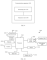
- FIG. 9 is a schematic block diagram of a communications apparatus according to an embodiment of this application.
- FIG. 10 is a schematic diagram of a structure of a terminal device according to an embodiment of this application.
- FIG. 11 is a schematic diagram of a structure of a network device according to an embodiment of this application.
- FIG. 12 is a schematic block diagram of an intelligent reflecting surface according to an embodiment of this application.
- the technical solutions in embodiments of this application may be applied to various communications systems, for example, a long term evolution (Long Term Evolution, LTE) system, an LTE frequency division duplex (frequency division duplex, FDD) system, an LTE time division duplex (time division duplex, TDD) system, a universal mobile telecommunications system (universal mobile telecommunications system, UMTS), a worldwide interoperability for microwave access (worldwide interoperability for microwave access, WiMAX) communications system, a future 5th generation (5th generation, 5G) mobile communications system, and a new radio access technology (new radio access technology, NR) system.
- the 5G mobile communications system may include non-standalone (non-standalone, NSA) and/or standalone (standalone, SA).
- the technical solutions provided in this application may be further applicable to a future communications system, for example, a sixth generation mobile communications system. This is not limited in this application.
- the network device may be any device having a wireless transceiver function.
- the device includes but is not limited to an evolved NodeB (evolved NodeB, eNB), a radio network controller (radio network controller, RNC), a NodeB (NodeB, NB), a base station controller (base station controller, BSC), a base transceiver station (base transceiver station, BTS), a home base station (for example, home evolved NodeB, or home NodeB, HNB), a baseband unit (baseband unit, BBU), an access point (access point, AP) in a wireless fidelity (wireless fidelity, Wi-Fi) system, a wireless relay node, a wireless backhaul node, a transmission point (transmission point, TP) or a transmission reception point (transmission reception point, TRP), or the like.
- eNB evolved NodeB
- RNC radio network controller
- NodeB NodeB
- BSC base station controller
- BTS base transce
- the device may be a gNB or a transmission point (TRP or TP) in a 5G system such as NR, or one or a group of antenna panels (including a plurality of antenna panels) of a base station in a 5G system.
- the device may be a network node constituting a gNB or a transmission point, such as a baseband unit (BBU) or a distributed unit (distributed unit, DU).
- BBU baseband unit
- DU distributed unit
- the gNB may include a centralized unit (centralized unit, CU) and a DU.
- the gNB may further include an active antenna unit (active antenna unit, AAU).
- the CU implements some functions of the gNB, and the DU implements some functions of the gNB.
- the CU is responsible for processing a non-real-time protocol and service, and implements functions of a radio resource control (radio resource control, RRC) layer and a packet data convergence protocol (packet data convergence protocol, PDCP) layer.
- RRC radio resource control
- PDCP packet data convergence protocol
- the DU is responsible for processing a physical layer protocol and a real-time service, and implements functions of a radio link control (radio link control, RLC) layer, a media access control (media access control, MAC) layer, and a physical (physical, PHY) layer.
- RLC radio link control
- MAC media access control
- PHY physical (physical, PHY) layer.
- the AAU implements some processing functions of the physical layer, radio frequency processing, and a function related to an active antenna.
- Information at the RRC layer is eventually converted into information at the PHY layer, or is converted from information at the PHY layer. Therefore, in this architecture, higher layer signaling such as RRC layer signaling may also be considered as being sent by the DU, or being sent by the DU and the AAU.
- the network device may be a device including one or more of a CU node, a DU node, and an AAU node.
- the CU may be classified as a network device in a radio access network (radio access network, RAN), or the CU may be classified as a network device in a core network (core network, CN). This is not limited in embodiments of this application.
- a terminal device may be referred to as user equipment (user equipment, UE), a terminal (terminal), a mobile station (mobile station, MS), a mobile terminal (mobile terminal), or the like.
- the terminal device may further communicate with one or more core networks through a radio access network (radio access network, RAN).
- the terminal device may also be referred to as an access terminal, a subscriber unit, a subscriber station, a mobile station, a mobile station, a remote station, a remote terminal, a mobile device, a user terminal, a terminal, a wireless communications device, a user agent, or a user apparatus.
- the terminal device may alternatively be a cellular phone, a cordless phone, a session initiation protocol (session initiation protocol, SIP) phone, a wireless local loop (wireless local loop, WLL) station, a personal digital assistant (personal digital assistant, PDA), a handheld device having a wireless communication function, a computing device, another processing device connected to a wireless modem, a vehicle-mounted device, a vehicle having a communication function, a wearable device, a terminal device in a future 5G network, or the like. This is not limited in embodiments of this application.
- SIP session initiation protocol
- WLL wireless local loop
- PDA personal digital assistant
- FIG. 1 is a schematic diagram of a wireless communications system to which a method is applied according to an embodiment of this application.
- the wireless communications system 100 may include at least two network devices, for example, a first network device 110 and a second network device 120 shown in FIG. 1 .
- the second network device 120 may be used as a relay (relay) station between the first network device 110 and a terminal device 130 .
- the second network device may alternatively be an intelligent reflecting surface (intelligent reflecting surface, IRS).
- IRS intelligent reflecting surface
- FIG. 2 an IRS 220 in a wireless communications system 200 may be used as a relay station between the first network device 110 and the terminal device 130 .
- the IRS 220 includes hundreds of thousands of passive metasurface array elements.
- the wireless communications system 100 includes at least one terminal device, for example, the terminal device 130 shown in FIG. 1 .
- the first network device and the terminal device may directly communicate with each other, for example, the first network device 110 shown in FIG. 1 may transmit data to the terminal device 130 through a downlink, or the terminal device 130 may transmit data to the first network device through an uplink.
- the first network device may perform reliable transmission with the terminal device by using the second network device.
- the first network device 110 transmits, to the second network device 120 , data to be transmitted to the terminal device 130 , and then the second network device 120 reflects the received data to the terminal device 130 .
- the terminal device 130 transmits, to the second network device 120 , data to be transmitted to the first network device 110 , and then the second network device 120 reflects the received data to the first network device 110 .
- the figure is merely an example.
- the figure shows one first network device, one terminal device, and one second network device.
- the communications system may further include more first network devices, terminal devices, and second network devices.
- the wireless communications system 100 may support downlink MIMO. Specifically, the wireless communications system 100 may support single-user multiple input multiple output (single-user multiple input multiple output, SU-MIMO), or the wireless communications system 100 may support multi-user multiple input multiple output (multi-user multiple input multiple output, MU-MIMO).
- the first network device 110 may send downlink data to a single user or to a plurality of users by using an existing spatial multiplexing technology. For brevity, details are not described herein.
- each array element in the second network device may independently perform amplitude and phase adjustment on an incident signal, to obtain a very high array gain.
- the second network device may further introduce an additional propagation path, to improve channel quality.
- the second network device is an IRS.
- the IRS controls a status of a semiconductor device on the back of each metasurface array element, for example, controls enabling and disabling of a PIN diode, so that each array element can independently perform amplitude and phase adjustment on an incident signal, to obtain a very high array gain.
- the IRS only needs to configure a simple control circuit to control an amplitude and phase modulation factor of each array element, and does not need to have a baseband capability, and therefore has very low power consumption and costs. Therefore, an intelligent reflecting surface aided multiple input multiple output (intelligent reflecting surface aided multiple input multiple output, IRS-aided MIMO) system formed by adding the IRS to a conventional MIMO system can further improve spectrum efficiency without significantly increasing power consumption and costs.
- the system 100 needs to know complete channel information to obtain the foregoing advantages.
- FDD downlink transmission is used as an example.
- the system 100 needs to separately know a vector of channel between the first network device and the terminal device and a vector of a channel between the first network device, the second network device, and the terminal device. Because there are hundreds of thousands of array elements in the second network device, the channel between the first network device, the second network device, and the terminal device is usually of a large dimension. Therefore, a method with low pilot overheads, a low delay, and high precision is urgently required to estimate the channel between the first network device, the second network device, and the terminal device.
- the second terminal device is an IRS.
- the IRS does not have a baseband function. Therefore, the channel between the first network device, the IRS, and the terminal device needs to be estimated on the terminal device side, and the channel can be estimated only by sending a channel state information-reference signal (channel state information-reference signal, CSI-RS) in a time division multiplexing (time division multiplexing, TDM) manner.
- CSI-RS channel state information-reference signal
- TDM time division multiplexing
- a current existing method for channel estimation in an IRS-aided MIMO system is as follows: First, the first network device notifies the IRS to disable all array elements. Then, the first network device sends a CSI-RS to the terminal device.
- the first network device may send the CSI-RS in a plurality of manners. For example, the first network device may send the CSI-RS in a TDM manner. Alternatively, the first network device may send the CSI-RS in a frequency division multiplexing (frequency division multiplexing. FDM) manner. Alternatively, the first network device may send the CSI-RS in a code division multiplexing (code division multiplexing, CDM) manner.
- the terminal device estimates a channel between the first network device and the terminal device based on the received signal.
- the first network device notifies the IRS to enable array elements one by one, and sends the CSI-RS in a TDM manner.
- the terminal device estimates the channel between the first network device, the IRS, and the terminal device, all array elements in the IRS are in a reflection disabled mode.
- the terminal device estimates the channel between the first network device, the IRS, and the terminal device, the IRS enables array elements one by one, so that the array elements are in a reflection enabled mode.
- the terminal device estimates channels corresponding to a case in which array elements are enabled, and the terminal device combines the channels corresponding to the case in which all the array elements are enabled and then subtracts the channel that is between the first network device and the terminal device and that is first estimated, to obtain the channel between the first network device, the IRS, and the terminal device.
- this application provides a method with low pilot overheads, a low delay, and high precision to estimate a channel between a first network device, a second network device, and a terminal device.
- “used to indicate” may include “used to directly indicate and “used to indirectly indicate”, or may include “explicitly indicate” and “implicitly indicate”.
- Information indicated by information is referred to as to-be-indicated information.
- the to-be-indicated information may be indicated in a plurality of manners, for example, but not limited to, a manner of directly indicating the to-be-indicated information.
- the to-be-indicated information or an index of the to-be-indicated information is indicated.
- the to-be-indicated information may be indirectly indicated by indicating other information, and there is an association relationship between the other information and the to-be-indicated information.
- the to-be-indicated information may be indicated, and the other part of the to-be-indicated information is known or agreed on in advance.
- it may alternatively be agreed on in advance (for example, specified in a protocol) that the to-be-indicated information is to be indicated depending on whether an information element exists, thereby reducing indication overheads to some extent.
- first the terms “first”. “second”, and various numbers in the following embodiments are merely used for differentiation for ease of description, and are not used to limit the scope of embodiments of this application. For example, the terms are used to distinguish between different time offset parameters and different information.
- descriptions such as “when”, “in a case”, and “if” mean that a device (for example, a terminal device or a network device) performs corresponding processing in an objective situation, and are not intended to limit time, and the device (for example, the terminal device or the network device) is not required to perform a determining action during implementation, and do not mean any other limitation.
- the terminal device shown in the following embodiments may be replaced with a component (for example, a chip, a chip system, or a circuit) configured in the terminal device.
- the network device shown in the following embodiments may also be replaced with a component (for example, a chip, a chip system, or a circuit) configured in the network device.
- the embodiments shown below do not specially limit a specific structure of an execution body of the method provided in embodiments of this application, provided that communication can be performed according to the method provided in embodiments of this application by running a program that records code of the method provided in embodiments of this application.
- the method provided in embodiments of this application may be performed by a terminal device, a first network device, or a second network device, or a functional module that is in the terminal device, the first network device, or the second network device and that can invoke and execute the program.
- FIG. 4 is a schematic flowchart of a method according to an embodiment of this application. As shown in FIG. 4 , the method 400 includes S 401 to S 406 . The steps are described in detail below.
- a first network device sends one or more first reference signals.
- a terminal device receives the one or more first reference signals from the first network device on a d th port of the terminal device.
- D is a quantity of ports of the terminal device, and D is a positive integer.
- a manner in which the first network device sends the first reference signal is not specifically limited in this embodiment of this application.
- the first network device may send the first reference signal in a TDM manner.
- the first network device may send the first reference signal in an FDM manner.
- the first network device may send the first reference signal in a CDM manner.
- the first reference signal sent by the first network device may be a reference signal precoded by the first network device based on a first precoding matrix.
- the first precoding matrix may be a codeword in a Type I/II codebook in R15.
- the terminal device may have one or more receive ports, and all receive ports of the terminal device receive the first reference signal.
- the terminal device obtains a first channel vector h 1,d on the d th port of the terminal device based on the received first reference signal.
- h 1,d is a channel vector of a channel between the first network device and the d th port of the terminal device.
- the terminal device receives N second reference signals on the d t h port of the terminal device.
- N is a quantity of ports of the second reference signal, and N is an integer greater than or equal to 2.
- the quantity of ports of the second reference signal is less than a quantity of ports of a second network device.
- each second reference signal is a reference signal generated by superimposing a first component and a second component.
- An n th first component corresponds to an n th third reference signal sent by the first network device
- an n th second component corresponds to an n th fourth reference signal sent by the second network device.
- the n th third reference signal is a reference signal precoded by the first network device based on the first precoding matrix
- the n th fourth reference signal is a reference signal generated after the second network device precodes the n th third reference signal based on a second precoding matrix, where n ⁇ [1, N].
- the terminal device may have one or more receive ports, and all receive ports of the terminal device receive the second reference signal.
- the N second reference signals received by the terminal device are sent in a TDM manner.
- the n th third reference signal may be directly transmitted to the terminal device through a channel between the first network device and the terminal device, and may also be transmitted to the terminal device through a channel between the first network device, the second network device, and the terminal device. Therefore, an n th second reference signal received by the terminal device may be understood as a reference signal generated by superimposing the n th third reference signal directly from the first network device and the n th fourth reference signal directly from the second network device.
- the second precoding matrix is used to process a fourth channel vector h 4,d to obtain a third channel vector h 3,d . If a quantity of ports of the third channel vector h 3,d is less than a quantity of ports of the fourth channel vector h 4,d , it may be further understood that the third channel vector h 3,d has sparsity.
- the second precoding matrix is used to process the fourth channel vector h 4,d , that is, perform spatial-domain compression on the fourth channel vector h 4,d , to obtain the third channel vector h 3,d having sparsity.
- V is a matrix formed by a group of orthogonal bases
- a specific form of b n is not limited in this embodiment of this application.
- the first precoding matrix may be a codeword in a Type I/II codebook in R15.
- the first precoding matrix may be used together with the second precoding matrix to process the fourth channel vector h 4,d .
- the terminal device obtains the first precoding matrix and the second precoding matrix is not limited in this embodiment of this application.
- the first precoding matrix and the second precoding matrix may be calculated by the terminal device.
- the terminal device sends the first precoding matrix and the second precoding matrix to the first network device.
- the first network device sends the second precoding matrix to the second network device.
- the first precoding matrix and the second precoding matrix may be calculated by the first network device.
- the first network device sends the first precoding matrix and the second precoding matrix to the terminal device.
- the first network device sends the second precoding matrix to the second network device.
- the first precoding matrix and the second precoding matrix may be specified in a communications protocol.
- the terminal device obtains a second channel vector h 2,d based on the N received second reference signals.
- S 401 and S 402 may be performed before or after S 403 and S 404 .
- the terminal device calculates a third channel vector h 3,d based on the obtained second channel vector h 2,d and the obtained first channel vector h 1,d .
- the terminal device calculates a fourth channel vector h 4,d based on the third channel vector h 3,d .
- the terminal device may calculate the fourth channel vector h 4,d by using a compressed sensing algorithm or an artificial intelligence algorithm.
- the terminal device may jointly obtain the third precoding matrix w and the fourth precoding matrix ⁇ based on the fourth channel vector h 4,d and the first channel vector h 1,d , and then send the third precoding matrix w and the fourth precoding matrix ⁇ to the first network device. Further, the first network device sends the received fourth precoding matrix ⁇ to the second network device.
- the third precoding matrix w is a precoding matrix used when the first network device transmits data to the terminal device
- the fourth precoding matrix ⁇ is a precoding matrix used when the second network device transmits data to the terminal device.
- a specific manner in which the first network device sends the fourth precoding matrix ⁇ is not limited in this embodiment of this application.
- the first network device sends the fourth precoding matrix ⁇ to the second network device by using wireless transmission dynamic signaling.
- the first network device sends the fourth precoding matrix ⁇ to the second network device by using RRC signaling.
- the first network device sends the fourth precoding matrix ⁇ to the second network device by using a wired transmission control signal.
- the terminal device iterates the following two processes by using a first indicator as an optimization target until the optimization target is no longer added: (1) fixing the third precoding matrix w and calculating the fourth precoding matrix ⁇ ; and (2) fixing the fourth precoding matrix ⁇ and calculating the third precoding matrix w .
- the first indicator includes one or more of the following: spectrum efficiency, energy efficiency, a transmission rate, and an error between the first indicator and a target transmission solution. If the first indicator is the spectrum efficiency, the energy efficiency, or the transmission rate, the optimization target is to maximize the first indicator. If the first indicator is the error between the first indicator and the target transmission solution, the optimization target is to minimize the first indicator, and the target transmission solution is an optimal transmission solution between the first network device, the second network device, and the terminal device.
- the terminal device calculates the fourth channel vector h 4,d and obtains the first channel vector h 1,d
- the terminal device sends the fourth channel vector h 4,d and the first channel vector h 1,d to the first network device.
- the first network device jointly obtains the third precoding matrix w and the fourth precoding matrix ⁇ based on the received fourth channel vector h 4,d and the received first channel vector h 1,d . Further, the first network device sends the fourth precoding matrix ⁇ to the second network device.
- the first network device may send the first reference signal through different ports in a TDM manner, in an FDM manner, or in a CDM manner. As shown in FIG. 5 ( a ) , the first network device sends the first reference signal through different ports on different time-frequency resource elements in a same slot. However, in a process in which the terminal device calculates the fourth channel vector h 4,d , the first network device sends the third reference signal in a TDM manner. As shown in FIG. 5 ( b ) , the first network device sends the third reference signal through different ports in different slots on a same time-frequency resource element.
- a quantity of time-frequency resource elements (resource elements, REs) occupied by the first reference signal needs to be greater than or equal to a quantity of ports of the first network device.
- a quantity of REs occupied when the second network device generates a fourth reference signal based on the third reference signal from the first network device, and sends the fourth reference signal to the terminal device is far less than a quantity of ports of the second network device.
- the second precoding matrix that has a spatial-domain compression function is designed to perform spatial-domain compression on the fourth channel vector h 4,d to obtain sparsity, to estimate h 4,d with a large quantity of ports based on h 3,d with a small quantity of ports. Therefore, in the method provided in this embodiment of this application, sparsity of the fourth channel vector h 4,d in space domain can be fully mined to reduce pilot overheads and a delay. In addition, all array gains of the second network device can be further obtained to improve an SNR and estimation precision of channel estimation.
- the first precoding matrix that has a spatial-domain compression function is further designed in this embodiment of this application. Therefore, sparsity of the fourth channel vector h 4,d in space domain can be further mined to reduce pilot overheads and a delay of channel estimation.
- M is a positive integer greater than or equal to 1
- T is a positive integer greater than or equal to 1.
- M is a positive integer greater than or equal to 1
- T is a positive integer greater than or equal to 1.
- the method provided in this embodiment of this application is also applicable to a scenario in which there are a plurality of terminal devices or a plurality of antennas are configured for the terminal device.
- FIG. 6 is a schematic flowchart of a method according to another embodiment of this application. As shown in FIG. 6 , the method 600 includes S 601 to S 610 . The steps are described in detail below.
- a first network device sends first indication information to an IRS.
- the IRS receives the first indication information from the network device.
- the first indication information is used to indicate the IRS to disable all array elements.
- the network device sends a first reference signal to a terminal device.
- the first reference signal is used to obtain a first channel vector h 1,d .
- the terminal device obtains the first channel vector h 3 .
- the network device sends second indication information to the IRS.
- the IRS receives the second indication information from the network device.
- the second indication information is used to indicate the IRS to enable all array elements.
- the terminal device receives a second reference signal.
- the second reference signal is used to obtain a second channel vector h 2,d .
- the terminal device calculates a fourth channel vector h 4,d .
- the terminal device calculates the fourth channel vector h 4,d based on the N received second reference signals.
- ⁇ 1 is an amplitude and phase modulation coefficient on an l th array element in the IRS
- l ⁇ [1,T] T is a quantity of ports of the IRS
- T is a positive integer.
- k n ⁇ (0, ⁇ 2 ) is complex white Gaussian noise
- ⁇ 2 is noise power
- ⁇ n [ ⁇ 1 , ⁇ 2 , . . . , ⁇ T ] H ⁇ T
- ⁇ n is equivalent to ⁇ n , that is, ⁇ n is the second precoding matrix.
- U ⁇ M ⁇ M is a matrix formed by a group of orthogonal bases, that is, a discrete Fourier transform (discrete Fourier transform, DFT) matrix, which can implement spatial-domain compression on each column of H 4
- v ⁇ T ⁇ T is a DFT matrix, which can implement spatial-domain compression on each row of the channel matrix H 4
- b n ⁇ N ⁇ l is a sampling vector.
- a specific form of b n is not limited in this embodiment of this application.
- b n may be a Bernoulli random vector, that is, each element of b n is randomly selected from a set ⁇ +1, ⁇ 1 ⁇ with an equal probability.
- the IRS in a reflection enabled mode selects one codeword from the beam codebook , that is, selects one second precoding matrix ⁇ n .
- the N second reference signals received by the terminal device may be represented as follows:
- Formula (5) may be considered to resolve a classical sparse signal reconstruction problem.
- a specific compressed sensing algorithm to be used to solve Formula (5) is not limited in this embodiment of this application.
- a learned approximate message passing (learned approximate message passing, LAMP) algorithm may be used.
- An essential idea of the LAMP algorithm is based on an iterative framework of a classical approximate message passing (approximate message passing, AMP) algorithm, and a neural network is used to learn an optimal iterative operation process, to avoid a performance loss caused by selecting a parameter such as a correction factor based on experience in the conventional AMP algorithm.
- a (t+1) th time of iterative process of the LAMP algorithm includes the following two steps:
- h ⁇ t + 1 ⁇ t ⁇ ⁇ st ( h ⁇ t + Av t ; ⁇ t M ⁇ ⁇ v t ⁇ 2 ) ( 6 )
- v t + 1 y - ⁇ ⁇ h ⁇ t + 1 + ⁇ t P ⁇ ⁇ h ⁇ t + 1 ⁇ 0 ⁇ v t ( 7 )
- ⁇ st ( ⁇ ) is a contraction function, and is defined as follows:
- the normalized mean square error is defined as follows:
- S 609 is performed by the terminal device.
- the terminal device reports the fourth channel vector h 4,d and the first channel vector h 1,d to the first network device in an implicit feedback manner.
- the terminal device first jointly obtains the third precoding matrix w and the fourth precoding matrix ⁇ based on the fourth channel vector h 4,d and the first channel vector h 1,d , and then sends the third precoding matrix w and the fourth precoding matrix ⁇ to the first network device. Because the terminal device feeds back only the third precoding matrix w and the fourth precoding matrix ⁇ , implicit feedback has low feedback overheads. However, because the terminal device cannot learn of a channel of another terminal device, an optimization result of implicit feedback usually causes heavy interference, and therefore implicit feedback is more applicable to a single-user scenario.
- S 609 is performed by the first network device.
- the terminal device reports the fourth channel vector h 4,d and the first channel vector h 1,d in an explicit feedback manner.
- the terminal device reports the fourth channel vector h 4,d and the first channel vector h 1,d to the first network device.
- the first network device jointly obtains the third precoding matrix w and the fourth precoding matrix ⁇ based on the received fourth channel vector h 4,d and the received first channel vector h 1,d . Because the terminal device needs to feed back high-dimensional channel information, explicit feedback has high feedback overheads. However, because the first network device has channel information of all terminal devices, explicit feedback can effectively eliminate multi-user interference, and therefore is more applicable to a multi-user scenario.
- a specific manner in which the terminal device or the first network device jointly obtains the third precoding matrix w and the fourth precoding matrix ⁇ is not limited in this embodiment of this application.
- the terminal device or the first network device may iterate the following two processes by using a first indicator as an optimization target until the optimization target is no longer added: (1) fixing the third precoding matrix w and calculating the fourth precoding matrix ⁇ ; and (2) fixing the fourth precoding matrix ⁇ and calculating the third precoding matrix w .
- the first indicator includes one or more of the following: spectrum efficiency, energy efficiency, a transmission rate, and an error between the first indicator and a target transmission solution. If the first indicator is the spectrum efficiency, the energy efficiency, or the transmission rate, the optimization target is to maximize the first indicator. If the first indicator is the error between the first indicator and the target transmission solution, the optimization target is to minimize the first indicator, and the target transmission solution is an optimal transmission solution between the first network device, the second network device, and the terminal device.
- An essential idea is to optimize another precoding matrix by fixing a precoding matrix, and perform alternate iteration until convergence, so that an unsolvable non-convex optimization problem can be transformed into a solvable optimization subproblem.
- an optimization problem of the transmission rate of the system may be represented as follows:
- a second constraint condition of the foregoing optimization problem is non-convex, and therefore the problem cannot be directly solved. Therefore, in this embodiment of this application, a suboptimal solution of the problem may be obtained in such a manner of fixing the third precoding matrix w , calculating the fourth precoding matrix ⁇ , fixing the fourth precoding matrix ⁇ , and calculating the third precoding matrix w .
- ⁇ is fixed, the foregoing problem is convex, and optimal w may be directly obtained through maximum ratio combining and is represented as follows:
- w _ ⁇ ⁇ ( h 1 , d H + ⁇ _ H ⁇ H 4 , d ) H ⁇ h 1 , d H + ⁇ _ H ⁇ H 4 , d ⁇ 2 11 )
- vec(H 4,d ) h 4,d , and ⁇ is a non-zero constant.
- optimal ⁇ may be obtained by using a triangle theorem, that is, an objective function is maximal only if phases of h 1,d w and ⁇ H H 4,d w are the same.
- optimal ⁇ may be represented as follows: exp( ⁇ j (arg( h 1,d w ) ⁇ arg( H 4,d w )) (12)
- arg(.) represents a phase extraction operation.
- Optimal ⁇ and optimal w may be obtained by repeatedly calculating Formulas (11) and (12) until an objective function in Formula (10) is no longer increased.
- network device precoding and IRS precoding may be selected from a codebook, for example, a Type I/II codebook in R15.
- a codeword that is closest to an optimization result (with a minimum Euclidean distance) may be selected from a correlated codebook as actual network device precoding and IRS precoding, and is reported in a manner of reporting the Type I/II codebook.
- array elements of the IRS may be grouped. As shown in FIG. 8 , for different array elements in a same group, in this embodiment of this application, only one amplitude and phase modulation factor is fed back, and a small performance loss is exchanged for a reduction in feedback overheads.
- the first network device sends the fourth precoding matrix ⁇ to the IRS.
- a specific manner in which the first network device sends the fourth precoding matrix ⁇ is not limited in this embodiment of this application.
- the first network device sends the fourth precoding matrix ⁇ to the IRS by using wireless transmission dynamic signaling.
- the first network device sends the fourth precoding matrix ⁇ to the IRS by using RRC signaling.
- the first network device sends the fourth precoding matrix to the IRS by using a wired transmission control signal.
- Pilot overheads of the conventional solution are N. This indicates that the pilot overheads can be reduced by more than 87.5% in this embodiment of this application.
- FIG. 9 is a schematic block diagram of a communications apparatus according to an embodiment of this application.
- a communications apparatus 1000 may include a processing unit 1100 and a transceiver unit 1200 .
- the communications apparatus 1000 may correspond to the terminal device in the foregoing method embodiment, for example, may be a terminal device, or a component (for example, a chip or a chip system) configured in the terminal device.
- the communications apparatus 1000 may correspond to the terminal device in the method 400 and the method 600 according to embodiments of this application.
- the communications apparatus 1000 may include units configured to perform the methods performed by the terminal device in the method 400 in FIG. 4 and the method 600 in FIG. 6 .
- the units in the communications apparatus 1000 and the foregoing other operations and/or functions are separately used to implement corresponding procedures of the method 400 in FIG. 4 and the method 600 in FIG. 6 .
- the processing unit 1100 may be configured to perform S 402 and S 404 to S 406 in the method 400
- the transceiver unit 1200 may be configured to perform S 401 and S 403 in the method 400 .
- the processing unit 1100 may be configured to perform S 602 , S 608 , and S 609 in the method 600
- the transceiver unit 1200 may be configured to perform steps S 603 , S 607 , and S 609 in the method 600 .
- the transceiver unit 1200 in the communications apparatus 1000 may be implemented by a transceiver, for example, may correspond to a transceiver 2020 in a terminal device 2000 shown in FIG. 10
- the processing unit 1100 in the communications apparatus 1000 may be implemented by at least one processor, for example, may correspond to a processor 2010 in the terminal device 2000 shown in FIG. 10 .
- the transceiver unit 1200 in the communications apparatus 1000 may be implemented by using an input/output interface
- the processing unit 1100 in the communications apparatus 1000 may be implemented by using a processor, a microprocessor, an integrated circuit, or the like integrated into the chip or the chip system.
- the communications apparatus 1000 may correspond to the first network device in the foregoing method embodiment, for example, may be a first network device, or a component (for example, a chip or a chip system) configured in the first network device.
- the communications apparatus 1000 may correspond to the first network device in the method 400 and the method 600 according to embodiments of this application.
- the communications apparatus 1000 may include units configured to perform the methods performed by the first network device in the method 400 in FIG. 4 and the method 600 in FIG. 6 .
- the units in the communications apparatus 1000 and the foregoing other operations and/or functions are separately used to implement corresponding procedures of the method 400 in FIG. 4 and the method 600 in FIG. 6 .
- the processing unit 1100 may be configured to perform S 401 and S 403 in the method 400
- the transceiver unit 1200 may be configured to perform S 401 and S 403 in the method 400 .
- the processing unit 1100 may be configured to perform S 609 in the method 600
- the transceiver unit 1200 may be configured to perform steps S 601 , S 603 , S 605 , S 607 , and S 610 in the method 600 .
- the transceiver unit 1200 in the communications apparatus 1000 may be implemented by a transceiver, for example, may correspond to a transceiver 3100 in a network device 3000 shown in FIG. 11
- the processing unit 1100 in the communications apparatus 1000 may be implemented by at least one processor, for example, may correspond to a processor 3200 in the network device 3000 shown in FIG. 11 .
- the transceiver unit 1200 in the communications apparatus 1000 may be implemented by using an input/output interface
- the processing unit 1100 in the communications apparatus 1000 may be implemented by using a processor, a microprocessor, an integrated circuit, or the like integrated into the chip or the chip system.
- the communications apparatus 1000 may correspond to the second network device in the foregoing method embodiment, for example, may be a second network device, or a component (for example, a chip or a chip system) configured in the second network device.
- the communications apparatus 1000 may correspond to the second network device in the method 400 according to this embodiment of this application.
- the communications apparatus 1000 may include units configured to perform the method performed by the second network device in the method 400 in FIG. 4 .
- the units in the communications apparatus 1000 and the foregoing other operations and/or functions are separately used to implement corresponding procedures of the method 400 in FIG. 4 .
- the processing unit 1100 may be configured to perform S 403 in the method 400
- the transceiver unit 1200 may be configured to perform S 403 in the method 400 .
- the transceiver unit 1200 in the communications apparatus 1000 may be implemented by a transceiver, for example, may correspond to a transceiver 3100 in a network device 3000 shown in FIG. 11
- the processing unit 1100 in the communications apparatus 1000 may be implemented by at least one processor, for example, may correspond to a processor 3200 in the network device 3000 shown in FIG. 11 .
- the transceiver unit 1200 in the communications apparatus 1000 may be implemented by using an input/output interface
- the processing unit 1100 in the communications apparatus 1000 may be implemented by using a processor, a microprocessor, an integrated circuit, or the like integrated into the chip or the chip system.
- the communications apparatus 1000 may correspond to the IRS in the foregoing method embodiment, for example, may be an IRS, or a component (for example, a chip or a chip system) configured in the IRS.
- the communications apparatus 1000 may correspond to the IRS in the method 600 according to this embodiment of this application.
- the communications apparatus 1000 may include units configured to perform the method performed by the IRS in the method 600 in FIG. 6 .
- the units in the communications apparatus 1000 and the foregoing other operations and/or functions are separately used to implement corresponding procedures of the method 600 in FIG. 6 .
- the processing unit 1100 may be configured to perform steps S 602 and S 606 in the method 600
- the transceiver unit 1200 may be configured to perform S 601 , S 605 , S 607 , and S 610 in the method 600 .
- the transceiver unit 1200 in the communications apparatus 1000 may be implemented by a transceiver, for example, may correspond to a transceiver 3100 in a network device 3000 shown in FIG. 11
- the processing unit 1100 in the communications apparatus 1000 may be implemented by at least one processor, for example, may correspond to a processor 3200 in the network device 3000 shown in FIG. 11 .
- the transceiver unit 1200 in the communications apparatus 1000 may be implemented by using an input/output interface
- the processing unit 1100 in the communications apparatus 1000 may be implemented by using a processor, a microprocessor, an integrated circuit, or the like integrated into the chip or the chip system.
- FIG. 10 is a schematic diagram of a structure of a terminal device 2000 according to an embodiment of this application.
- the terminal device 2000 may be used in the system shown in FIG. 1 , to perform a function of the terminal device in the foregoing method embodiments.
- the terminal device 2000 includes a processor 2010 and a transceiver 2020 .
- the terminal device 2000 further includes a memory 2030 .
- the processor 2010 , the transceiver 2020 , and the memory 2030 may communicate with each other through an internal connection path, to transfer a control signal and/or a data signal.
- the memory 2030 is configured to store a computer program.
- the processor 2010 is configured to invoke the computer program from the memory 2030 and run the computer program, to control the transceiver 2020 to receive and send a signal.
- the terminal device 2000 may further include an antenna 2040 , configured to send, by using a radio signal, uplink data or uplink control signaling output by the transceiver 2020 .
- the processor 2010 and the memory 2030 may be integrated into one processing apparatus.
- the processor 2010 is configured to execute program code stored in the memory 2030 , to implement the foregoing functions.
- the memory 2030 may alternatively be integrated into the processor 2010 , or may be independent of the processor 2010 .
- the processor 2010 may correspond to the processing unit 1100 ) in FIG. 9 .
- the transceiver 2020 may correspond to the transceiver unit 1200 in FIG. 9 , and may also be referred to as a transceiver unit.
- the transceiver 2020 may include a receiver (which is also referred to as a receiver machine or a receiver circuit) and a transmitter (which is also referred to as a transmitter machine or a transmitter circuit).
- the receiver is configured to receive a signal
- the transmitter is configured to transmit a signal.
- the terminal device 2000 shown in FIG. 10 can implement processes of the terminal device in the method embodiments shown in FIG. 4 and FIG. 6 . Operations and/or functions of the modules in the terminal device 2000 are separately intended to implement corresponding procedures in the foregoing method embodiments. For details, refer to the descriptions in the foregoing method embodiments. To avoid repetition, detailed descriptions are appropriately omitted herein.
- the processor 2010 may be configured to perform the actions that are implemented by the terminal device and that are described in the foregoing method embodiments, for example, estimate a fourth channel vector and estimate a first channel vector.
- the transceiver 2020 may be configured to perform the actions of sending to the first network device by the terminal device or receiving from the first network device or the second network device by the terminal device and that are described in the foregoing method embodiments, for example, send a first channel vector and a fourth channel vector, and receive a reference signal.
- send a first channel vector and a fourth channel vector for example, send a first channel vector and a fourth channel vector, and receive a reference signal.
- the terminal device 2000 may further include a power supply 2050 , configured to supply power to various components or circuits in the terminal device.
- the terminal device 2000 may further include one or more of an input unit 2060 , a display unit 2070 , an audio circuit 2080 , a camera 2090 , a sensor 2100 , and the like, and the audio circuit may further include a speaker 2082 , a microphone 2084 , and the like.
- FIG. 11 is a schematic diagram of a structure of a network device according to an embodiment of this application, for example, may be a schematic diagram of a structure of a base station.
- the base station 3000 may be applied to the system shown in FIG. 1 , and perform functions of the first network device or the second network device in the foregoing method embodiments.
- the base station 3000 may include one or more radio frequency units, for example, a remote radio unit (remote radio unit, RRU) 3100 , and one or more baseband units (BBUs) (which may also be referred to as distributed units (DUs)) 3200 .
- RRU remote radio unit
- BBUs baseband units
- DUs distributed units
- the RRU 3100 may be referred to as a transceiver unit or a part of the transceiver unit, and corresponds to the transceiver unit 1100 in FIG. 9 .
- the transceiver unit 3100 may also be referred to as a transceiver machine, a transceiver circuit, a transceiver, or the like, and may include at least one antenna 3101 and a radio frequency unit 3102 .
- the transceiver unit 3100 may include a receiving unit and a sending unit.
- the receiving unit may correspond to a receiver (which is also be referred to as a receiver machine or a receiver circuit), and the sending unit may correspond to a transmitter (which is also be referred to as a transmitter machine or a transmitter circuit).
- the RRU 3100 is mainly configured to: receive and send a radio frequency signal, and perform conversion between a radio frequency signal and a baseband signal, for example, configured to send a reference signal to a terminal device, and receive a first channel vector and a fourth channel vector.
- the BBU 3200 is mainly configured to: perform baseband processing, control a base station, and the like.
- the RRU 3100 and the BBU 3200 may be physically disposed together, or may be physically disposed separately, namely, a distributed base station.
- the BBU 3200 is a control center of the base station, or may be referred to as a processing unit.
- the BBU 3200 may correspond to the processing unit 1200 in FIG. 9 , and is mainly configured to implement a baseband processing function, for example, channel coding, multiplexing, modulation, or spreading.
- the BBU (processing unit) may be configured to control the base station to perform an operation procedure of the first network device in the foregoing method embodiment, for example, generate a first reference signal.
- the BBU (processing unit) may be configured to control the base station to perform an operation procedure of the second network device in the foregoing method embodiment, for example, generate a third reference signal.
- the BBU may be configured to control the base station to perform an operation procedure of the second network device in the foregoing method embodiment, for example, generate a third reference signal.
- the BBU 3200 may include one or more boards.
- a plurality of boards may jointly support a radio access network (for example, an LTE network) having a single access standard, or may separately support radio access networks (for example, an LTE network, a 5G network, or another network) having different access standards.
- the BBU 3200 further includes a memory 3201 and a processor 3202 .
- the memory 3201 is configured to store necessary instructions and data.
- the processor 3202 is configured to control the base station to perform a necessary action, for example, is configured to control the base station to perform the operation procedure related to the network device in the foregoing method embodiments.
- the memory 3201 and the processor 3202 may serve the one or more boards. In other words, a memory and a processor may be independently disposed on each board, or the plurality of boards may share a same memory and a same processor. In addition, a necessary circuit may further be disposed on each board.
- the base station 3000 shown in FIG. 11 can implement processes of the first network device in the method embodiments shown in FIG. 4 and FIG. 6 .
- Operations and/or functions of the modules in the base station 3000 are separately intended to implement corresponding procedures in the foregoing method embodiments.
- the base station 3000 shown in FIG. 11 can implement processes of the second network device in the method embodiment shown in FIG. 4 .
- Operations and/or functions of the modules in the base station 300 ) are separately intended to implement corresponding procedures in the foregoing method embodiments.
- the BBU 3200 may be configured to perform the actions that are implemented by the first network device or the second network device and that are described in the foregoing method embodiments
- the RRU 3100 may be configured to perform the actions that are of sending to the terminal device by the first network device or receiving from the terminal device by the first network device and that are described in the foregoing method embodiments, or the actions that are of receiving from the first network device by the second network device or sending to the terminal device by the second network device and that are described in the foregoing method embodiments.
- the base station 3000 shown in FIG. 11 is merely a possible form of the network device, and should not constitute any limitation on this application.
- the method provided in this application may be applied to a network device in another form.
- the network device includes an AAU, and may further include a CU and/or a DU, or may include a BBU and an adaptive radio unit (adaptive radio unit, ARU) or a BBU.
- the network device may be customer premises equipment (customer premises equipment, CPE), or may be a network device in another form.
- a specific form of the network device is not limited in this application.
- the CU and/or the DU may be configured to perform the actions that are implemented by the network device and that are described in the foregoing method embodiments
- the AAU may be configured to perform the actions that are of sending to the first terminal device by the network device or receiving from the first terminal device by the network device and that are described in the foregoing method embodiments.
- FIG. 12 is a schematic block diagram of an IRS 4000 according to an embodiment of this application.
- the IRS 4000 may be applied to the system shown in FIG. 2 , and perform functions of the IRS in the foregoing method embodiments.
- the IRS 4000 includes a processor 4100 and a transceiver 4200 .
- the processor 4100 is connected to the transceiver 4200 .
- the IRS 4000 further includes a memory 4300 , and the memory 4300 is connected to the processor 4100 .
- the processor 4100 , the memory 4300 , and the transceiver 4200 may communicate with each other through an internal connection path.
- the processor 4100 may be configured to perform the actions that are implemented by the IRS and that are described in the foregoing method embodiments, for example, generate a fourth reference signal.
- the transceiver 2020 may be configured to perform the actions that are of sending to the terminal device by the IRS or receiving from the first network device by the IRS and that are described in the foregoing method embodiments, for example, send a fourth reference signal and receive a third reference signal.
- the IRS 4000 shown in FIG. 12 can implement processes of the IRS in the method embodiment shown in FIG. 6 .
- Operations and/or functions of the modules in the IRS 4000 are separately intended to implement corresponding procedures in the foregoing method embodiments.
- An embodiment of this application further provides a processing apparatus, including a processor and an interface.
- the processor is configured to perform the method in any one of the foregoing method embodiments.
- the processing apparatus may be one or more chips.
- the processing apparatus may be a field programmable gate array (field programmable gate array, FPGA), an application-specific integrated circuit (application-specific integrated circuit, ASIC), a system on chip (system on chip, SoC), a central processing unit (central processing unit, CPU), a network processor (network processor, NP), a digital signal processing circuit (digital signal processor. DSP), a micro controller unit (micro controller unit, MCU), a programmable controller (programmable logic device, PLD), or another integrated chip.
- steps in the foregoing methods may be implemented by using a hardware integrated logical circuit in the processor, or by using instructions in a form of software.
- the steps of the methods disclosed with reference to embodiments of this application may be directly performed by a hardware processor, or may be performed by a combination of hardware and software modules in the processor.
- the software module may be located in a mature storage medium in the art, such as a random access memory, a flash memory, a read-only memory, a programmable read-only memory, an electrically erasable programmable memory, or a register.
- the storage medium is located in the memory, and the processor reads information in the memory and completes the steps in the foregoing methods in combination with hardware of the processor. To avoid repetition, details are not described herein again.
- the processor in embodiments of this application may be an integrated circuit chip, and has a signal processing capability.
- steps in the foregoing method embodiments may be implemented by using a hardware integrated logic circuit in the processor, or by using instructions in a form of software.
- the foregoing processor may be a general-purpose processor, a digital signal processor (DSP), an application-specific integrated circuit (ASIC), a field programmable gate array (FPGA) or another programmable logic device, a discrete gate or a transistor logic device, or a discrete hardware component.
- DSP digital signal processor
- ASIC application-specific integrated circuit
- FPGA field programmable gate array
- the processor may implement or perform the methods, the steps, and logical block diagrams that are disclosed in embodiments of this application.
- the general-purpose processor may be a microprocessor, or the processor may be any conventional processor or the like.
- the steps of the methods disclosed with reference to embodiments of this application may be directly performed by a hardware decoding processor, or may be performed by a combination of hardware and software modules in a decoding processor.
- the software module may be located in a mature storage medium in the art, such as a random access memory, a flash memory, a read-only memory, a programmable read-only memory, an electrically erasable programmable memory, or a register.
- the storage medium is located in the memory, and the processor reads information in the memory and completes the steps in the foregoing methods in combination with hardware of the processor.
- the memory may be a volatile memory or a non-volatile memory, or may include both a volatile memory and a non-volatile memory.
- the non-volatile memory may be a read-only memory (read-only memory, ROM), a programmable read-only memory (programmable ROM, PROM), an erasable programmable read-only memory (erasable PROM, EPROM), an electrically erasable programmable read-only memory (electrically EPROM, EEPROM), or a flash memory.
- the volatile memory may be a random access memory (random access memory, RAM), and is used as an external cache.
- RAMs may be used, for example, a static random access memory (static RAM, SRAM), a dynamic random access memory (dynamic RAM, DRAM), a synchronous dynamic random access memory (synchronous DRAM, SDRAM), a double data rate synchronous dynamic random access memory (double data rate SDRAM, DDR SDRAM), an enhanced synchronous dynamic random access memory (enhanced SDRAM, ESDRAM), a synchlink dynamic random access memory (synchlink DRAM, SLDRAM), and a direct Rambus dynamic random access memory (direct Rambus RAM, DR RAM).
- static random access memory static random access memory
- DRAM dynamic random access memory
- DRAM dynamic random access memory
- SDRAM synchronous dynamic random access memory
- double data rate SDRAM double data rate SDRAM
- DDR SDRAM double data rate SDRAM
- ESDRAM enhanced synchronous dynamic random access memory
- synchlink dynamic random access memory synchlink dynamic random access memory
- direct Rambus RAM direct Rambus RAM
- this application further provides a computer program product.
- the computer program product includes computer program code.
- the computer program code When the computer program code is run on a computer, the computer is enabled to perform the methods respectively performed by the terminal device, the first network device, and the second network device in the embodiments shown in FIG. 4 and FIG. 6 .
- this application further provides a computer-readable medium.
- the computer-readable medium stores program code.
- the program code When the program code is run on a computer, the computer is enabled to perform the methods respectively performed by the terminal device, the first network device, and the second network device in the embodiments shown in FIG. 4 and FIG. 6 .
- this application further provides a system.
- the system includes the one or more terminal devices, the one or more first network devices, and the one or more second network devices.
- the first network device, the second network device, and the terminal device in the foregoing apparatus embodiments completely correspond to the first network device, the second network device, and the terminal device in the method embodiments, and corresponding modules or units perform corresponding steps.
- a communications unit transmits the steps of receiving or sending in the method embodiments
- a processing unit may perform a step other than the sending and receiving steps.
- a function of a specific unit refer to a corresponding method embodiment.
- a component may be, but is not limited to, a process that runs on a processor, a processor, an object, an executable file, a thread of execution, a program, and/or a computer.
- a computing device and an application that runs on the computing device may be components.
- One or more components may reside in a process and/or a thread of execution, and the component may be located on one computer and/or distributed between two or more computers.
- these components may be executed from various computer-readable media that store various data structures.
- the components may communicate by using a local and/or remote process and based on, for example, a signal having one or more data packets (for example, data from two components interacting with another component in a local system, in a distributed system, and/or across a network such as the internet interacting with other systems by using the signal).
- a signal having one or more data packets (for example, data from two components interacting with another component in a local system, in a distributed system, and/or across a network such as the internet interacting with other systems by using the signal).
- the disclosed system, the apparatus, and the method may be implemented in another manner.
- the described apparatus embodiments are merely examples.
- division into the units is merely logical function division.
- a plurality of units or components may be combined or integrated into another system, or some features may be ignored or not performed.
- the displayed or discussed mutual couplings or direct couplings or communications connections may be implemented through some interfaces.
- the indirect couplings or communications connections between apparatuses or units may be implemented in an electronic form, a mechanical form, or another form.
- the units described as separate components may or may not be physically separated, and components displayed as units may or may not be physical units. That is, the units may be located at one position, or may be distributed to a plurality of network units. Some or all of the units may be selected based on actual requirements to achieve the objectives of the solutions of the embodiments.
- function units in embodiments of this application may be integrated into one processing unit, or each of the units may exist alone physically, or two or more units may be integrated into one unit.
- all or some of the functions of the function units may be implemented by software, hardware, firmware, or any combination thereof.
- the software is used to implement the embodiments, all or some of the embodiments may be implemented in a form of a computer program product.
- the computer program product includes one or more computer instructions (programs).
- programs When the computer program instructions (programs) are loaded and executed on a computer, the procedures or functions according to embodiments of this application are all or partially generated.
- the computer may be a general-purpose computer, a dedicated computer, a computer network, or another programmable apparatus.
- the computer instructions may be stored in a computer-readable storage medium or may be transmitted from a computer-readable storage medium to another computer-readable storage medium.
- the computer instructions may be transmitted from a website, a computer, a server, or a data center to another website, computer, server, or data center in a wired (for example, a coaxial cable, an optical fiber, or a digital subscriber line (digital subscriber line, DSL)) or wireless (for example, infrared, radio, or microwave) manner.
- the computer-readable storage medium may be any usable medium accessible by a computer, or a data storage device, for example, a server or a data center, integrating one or more usable media.
- the usable medium may be a magnetic medium (for example, a floppy disk, a hard disk, or a magnetic tape), an optical medium (for example, a high-density digital video disc (digital video disc, DVD)), a semiconductor medium (for example, a solid state drive (solid state drive, SSD)), or the like.
- a magnetic medium for example, a floppy disk, a hard disk, or a magnetic tape
- an optical medium for example, a high-density digital video disc (digital video disc, DVD)
- a semiconductor medium for example, a solid state drive (solid state drive, SSD)
- the functions When the functions are implemented in a form of a software function unit and sold or used as an independent product, the functions may be stored in a computer-readable storage medium. Based on such an understanding, the technical solutions of this application essentially or the part contributing to the conventional technology, or some of the technical solutions may be implemented in a form of a software product.
- the computer software product is stored in a storage medium, and includes several instructions for instructing a computer device (which may be a personal computer, a server, a network device, or the like) to perform all or some of the steps of the methods in embodiments of this application.
- the foregoing storage medium includes any medium that can store program code such as a USB flash drive, a removable hard disk, a read-only memory (read-only memory, ROM), a random access memory (random access memory. RAM), a magnetic disk, or an optical disc.
- program code such as a USB flash drive, a removable hard disk, a read-only memory (read-only memory, ROM), a random access memory (random access memory. RAM), a magnetic disk, or an optical disc.
Abstract
Description
where vec(H4,d)=h4,d, and α is a non-zero constant.
where vec(H4,d)=h4,d, and α is a non-zero constant.
where vec(H4,d)=h4,d, and α is a non-zero constant.
where vec(H4,d)=h4,d, and α is a non-zero constant.
where vec(H4,d)=h4,d, and α is a non-zero constant.
y n=(h 1,d +h r HΘn G r H)w n x n +k n (1)
y n=(h 1,d+θn H diag(h r H)G r H)w n x n (2)
has obvious sparsity,
and N<<T. Therefore, Formula (5) may be considered to resolve a classical sparse signal reconstruction problem. Many classical compressed sensing algorithms may be used to solve hs, and then h4,d=vec(H4) is recovered based on the relationship hs≙vec(vHH4U).
exp(−j(arg(h 1,d
Claims (18)
Applications Claiming Priority (1)
| Application Number | Priority Date | Filing Date | Title |
|---|---|---|---|
| PCT/CN2019/117400 WO2021092746A1 (en) | 2019-11-12 | 2019-11-12 | Channel information obtaining method |
Related Parent Applications (1)
| Application Number | Title | Priority Date | Filing Date |
|---|---|---|---|
| PCT/CN2019/117400 Continuation WO2021092746A1 (en) | 2019-11-12 | 2019-11-12 | Channel information obtaining method |
Publications (2)
| Publication Number | Publication Date |
|---|---|
| US20220271805A1 US20220271805A1 (en) | 2022-08-25 |
| US11923929B2 true US11923929B2 (en) | 2024-03-05 |
Family
ID=75911334
Family Applications (1)
| Application Number | Title | Priority Date | Filing Date |
|---|---|---|---|
| US17/741,143 Active 2040-02-29 US11923929B2 (en) | 2019-11-12 | 2022-05-10 | Channel information obtaining method |
Country Status (4)
| Country | Link |
|---|---|
| US (1) | US11923929B2 (en) |
| EP (1) | EP4047978A4 (en) |
| CN (1) | CN114642019B (en) |
| WO (1) | WO2021092746A1 (en) |
Families Citing this family (5)
| Publication number | Priority date | Publication date | Assignee | Title |
|---|---|---|---|---|
| CN113676226B (en) * | 2020-05-15 | 2023-03-14 | 维沃移动通信有限公司 | Pilot information symbol transmission method, channel estimation method, communication device, and medium |
| CN113541760B (en) * | 2021-07-20 | 2023-11-07 | 南京邮电大学 | Intelligent reflection unit selection method based on energy efficiency and Internet of things system using same |
| WO2024044919A1 (en) * | 2022-08-29 | 2024-03-07 | 华为技术有限公司 | Communication method and apparatus |
| WO2024044990A1 (en) * | 2022-08-30 | 2024-03-07 | 北京小米移动软件有限公司 | Pre-coding method and apparatus based on reconfigurable intelligent surface |
| WO2024049801A1 (en) * | 2022-08-31 | 2024-03-07 | Interdigital Patent Holdings, Inc. | Reconfigurable intelligent surface/reconfigurable holographic surface-based joint precoding, beamforming, and modulation |
Citations (12)
| Publication number | Priority date | Publication date | Assignee | Title |
|---|---|---|---|---|
| US20100034146A1 (en) * | 2008-08-07 | 2010-02-11 | Qualcomm Incorporated | Method and apparatus for supporting multi-user and single-user mimo in a wireless communication system |
| US20130242896A1 (en) | 2012-03-19 | 2013-09-19 | Lg Electronics Inc. | Method and apparatus for receiving a signal in a wireless communication system that supports mu-mimo scheme |
| US20140064400A1 (en) * | 2012-08-06 | 2014-03-06 | Telefonaktiebolaget L M Ericsson (Publ) | Systems and methods for reporting pilot signal power information in a four branch mimo system |
| US20150003573A1 (en) * | 2013-06-28 | 2015-01-01 | Stefan Fechtel | Method and device for channel estimation with colliding interference cancellation |
| US20150207555A1 (en) * | 2012-07-16 | 2015-07-23 | Lg Electronics Inc. | Method and device for feeding back channel information in wireless communication system supporting multi-input multi-output scheme |
| US20160112167A1 (en) * | 2013-04-02 | 2016-04-21 | Panasonic Intellectual Property Corporation Of America | Method of mapping csi-rs ports to antenna units, base station and user equipment |
| US20160142189A1 (en) | 2014-11-07 | 2016-05-19 | Electronics And Telecommunications Research Institute | Method and apparatus for transmitting reference signal, method and apparatus for measuring and reporting channel state information, and method for configuring the same |
| US20160143055A1 (en) * | 2014-11-18 | 2016-05-19 | Telefonaktiebolaget L M Ericsson (Publ) | Signaling adapted csi-rs periodicities in active antenna systems |
| US20190021092A1 (en) * | 2017-07-12 | 2019-01-17 | Qualcomm Incorporated | Spatial listen before talk |
| CN109302220A (en) | 2017-07-25 | 2019-02-01 | 华为技术有限公司 | Methods, devices and systems for data transmission |
| CN109495149A (en) | 2017-09-11 | 2019-03-19 | 华为技术有限公司 | Communication means, the network equipment, terminal device and system |
| US20210075474A1 (en) * | 2019-09-09 | 2021-03-11 | Qualcomm Incorporated | Beam training in millimeter wave relays using amplify-and-forward transmissions |
-
2019
- 2019-11-12 WO PCT/CN2019/117400 patent/WO2021092746A1/en unknown
- 2019-11-12 EP EP19952335.8A patent/EP4047978A4/en active Pending
- 2019-11-12 CN CN201980102152.3A patent/CN114642019B/en active Active
-
2022
- 2022-05-10 US US17/741,143 patent/US11923929B2/en active Active
Patent Citations (12)
| Publication number | Priority date | Publication date | Assignee | Title |
|---|---|---|---|---|
| US20100034146A1 (en) * | 2008-08-07 | 2010-02-11 | Qualcomm Incorporated | Method and apparatus for supporting multi-user and single-user mimo in a wireless communication system |
| US20130242896A1 (en) | 2012-03-19 | 2013-09-19 | Lg Electronics Inc. | Method and apparatus for receiving a signal in a wireless communication system that supports mu-mimo scheme |
| US20150207555A1 (en) * | 2012-07-16 | 2015-07-23 | Lg Electronics Inc. | Method and device for feeding back channel information in wireless communication system supporting multi-input multi-output scheme |
| US20140064400A1 (en) * | 2012-08-06 | 2014-03-06 | Telefonaktiebolaget L M Ericsson (Publ) | Systems and methods for reporting pilot signal power information in a four branch mimo system |
| US20160112167A1 (en) * | 2013-04-02 | 2016-04-21 | Panasonic Intellectual Property Corporation Of America | Method of mapping csi-rs ports to antenna units, base station and user equipment |
| US20150003573A1 (en) * | 2013-06-28 | 2015-01-01 | Stefan Fechtel | Method and device for channel estimation with colliding interference cancellation |
| US20160142189A1 (en) | 2014-11-07 | 2016-05-19 | Electronics And Telecommunications Research Institute | Method and apparatus for transmitting reference signal, method and apparatus for measuring and reporting channel state information, and method for configuring the same |
| US20160143055A1 (en) * | 2014-11-18 | 2016-05-19 | Telefonaktiebolaget L M Ericsson (Publ) | Signaling adapted csi-rs periodicities in active antenna systems |
| US20190021092A1 (en) * | 2017-07-12 | 2019-01-17 | Qualcomm Incorporated | Spatial listen before talk |
| CN109302220A (en) | 2017-07-25 | 2019-02-01 | 华为技术有限公司 | Methods, devices and systems for data transmission |
| CN109495149A (en) | 2017-09-11 | 2019-03-19 | 华为技术有限公司 | Communication means, the network equipment, terminal device and system |
| US20210075474A1 (en) * | 2019-09-09 | 2021-03-11 | Qualcomm Incorporated | Beam training in millimeter wave relays using amplify-and-forward transmissions |
Non-Patent Citations (6)
| Title |
|---|
| Extended European Search Report in European Appln No. 19952335.8, dated Feb. 2, 2023, 17 pages. |
| PCT International Search Report and Written Opinion issued in International Application No. PCT/CN2019/117400 dated Jul. 27, 2020, 15 pages (with English translation). |
| Qurrat-Ul-Ain Nadeem et al., "Intelligent Reflecting Surface Assisted Multi-User MISO Communication," arxiv.org arXiv: 1906.02360v1, Jun. 6, 2019, 8 pages. |
| Supplementary European Search Report in European Appln No. 19952335.8, dated Oct. 18, 2022, 16 pages. |
| Wu et al., "Intelligent Reflecting Surface Enhanced Wireless Network: Joint Active and Passive Beamforming Design," 2018 IEEE Global Communications Conference, arXiv:1809.01423v2, Sep. 12, 2018, 6 pages. |
| Yang et al., "Intelligent Reflecting Surface Meets OFDM: Protocol Design and Rate Maximization," arxiv.org arXiv: 1906.09956v1, Jun. 21, 2019, 30 pages. |
Also Published As
| Publication number | Publication date |
|---|---|
| WO2021092746A1 (en) | 2021-05-20 |
| US20220271805A1 (en) | 2022-08-25 |
| EP4047978A1 (en) | 2022-08-24 |
| EP4047978A4 (en) | 2023-03-08 |
| CN114642019B (en) | 2023-12-08 |
| CN114642019A (en) | 2022-06-17 |
Similar Documents
| Publication | Publication Date | Title |
|---|---|---|
| US11923929B2 (en) | Channel information obtaining method | |
| US11277175B2 (en) | System and method for communications system training | |
| US20220094412A1 (en) | Channel Measurement Method and Communications Apparatus | |
| US20220263560A1 (en) | Channel state information reporting method and communications apparatus | |
| WO2019029345A1 (en) | System and method for transmit power control | |
| US20220109479A1 (en) | Methods and Apparatus for Operating in a Wideband Communication System | |
| EP4027543A1 (en) | Channel measurement method and communication apparatus | |
| JP7238167B2 (en) | Precoding matrix display and determination method, and communication device | |
| US11546041B2 (en) | Method and apparatus for beamspace processing based on multiple beamspace bases | |
| WO2021083157A1 (en) | Precoding matrix processing method and communication apparatus | |
| US11184208B2 (en) | Communication method, communications apparatus, and system | |
| WO2020143580A1 (en) | Vector indication method for constructing precoding vector, and communication apparatus | |
| US20230051245A1 (en) | Methods and Apparatus for Channel Estimation and Precoding with Incomplete Channel Observation and Channel State Information Feedback | |
| WO2019219022A1 (en) | Communication method, terminal device, and network device | |
| US20230013510A1 (en) | Method for indicating channel state information csi measurement and communication apparatus | |
| US20220416866A1 (en) | Channel state information feedback method and communications apparatus | |
| US20220271900A1 (en) | Method for configuring transmit port of downlink reference signal and communication apparatus | |
| US20230019630A1 (en) | Update Method and Communications Apparatus | |
| WO2024001744A1 (en) | Channel state information reporting method and communication apparatus | |
| WO2024027387A1 (en) | Information transmission method and apparatus | |
| US20230353207A1 (en) | Communication method and apparatus | |
| US20230239028A1 (en) | Channel measurement method and communication apparatus | |
| EP4224731A1 (en) | Channel measurement method and communication apparatus |
Legal Events
| Date | Code | Title | Description |
|---|---|---|---|
| FEPP | Fee payment procedure |
Free format text: ENTITY STATUS SET TO UNDISCOUNTED (ORIGINAL EVENT CODE: BIG.); ENTITY STATUS OF PATENT OWNER: LARGE ENTITY |
|
| STPP | Information on status: patent application and granting procedure in general |
Free format text: DOCKETED NEW CASE - READY FOR EXAMINATION |
|
| STPP | Information on status: patent application and granting procedure in general |
Free format text: NOTICE OF ALLOWANCE MAILED -- APPLICATION RECEIVED IN OFFICE OF PUBLICATIONS |
|
| STPP | Information on status: patent application and granting procedure in general |
Free format text: AWAITING TC RESP., ISSUE FEE NOT PAID |
|
| STPP | Information on status: patent application and granting procedure in general |
Free format text: NOTICE OF ALLOWANCE MAILED -- APPLICATION RECEIVED IN OFFICE OF PUBLICATIONS |
|
| AS | Assignment |
Owner name: HUAWEI TECHNOLOGIES CO., LTD., CHINA Free format text: ASSIGNMENT OF ASSIGNORS INTEREST;ASSIGNORS:GAO, XINYU;LIU, KUNPENG;REEL/FRAME:066082/0075 Effective date: 20240108 |
|
| STPP | Information on status: patent application and granting procedure in general |
Free format text: PUBLICATIONS -- ISSUE FEE PAYMENT VERIFIED |
|
| STCF | Information on status: patent grant |
Free format text: PATENTED CASE |