US11903336B2 - Ring elevator for lifting root crops in a root crop harvester and root crop harvester comprising such a ring elevator - Google Patents
Ring elevator for lifting root crops in a root crop harvester and root crop harvester comprising such a ring elevator Download PDFInfo
- Publication number
- US11903336B2 US11903336B2 US17/015,113 US202017015113A US11903336B2 US 11903336 B2 US11903336 B2 US 11903336B2 US 202017015113 A US202017015113 A US 202017015113A US 11903336 B2 US11903336 B2 US 11903336B2
- Authority
- US
- United States
- Prior art keywords
- strips
- belts
- chains
- distance
- ring elevator
- Prior art date
- Legal status (The legal status is an assumption and is not a legal conclusion. Google has not performed a legal analysis and makes no representation as to the accuracy of the status listed.)
- Active, expires
Links
- 230000001174 ascending effect Effects 0.000 claims abstract description 55
- 230000000630 rising effect Effects 0.000 claims description 7
- 230000015572 biosynthetic process Effects 0.000 claims description 6
- 238000007873 sieving Methods 0.000 description 8
- 238000003306 harvesting Methods 0.000 description 7
- 230000008901 benefit Effects 0.000 description 5
- 241001124569 Lycaenidae Species 0.000 description 3
- PCTMTFRHKVHKIS-BMFZQQSSSA-N (1s,3r,4e,6e,8e,10e,12e,14e,16e,18s,19r,20r,21s,25r,27r,30r,31r,33s,35r,37s,38r)-3-[(2r,3s,4s,5s,6r)-4-amino-3,5-dihydroxy-6-methyloxan-2-yl]oxy-19,25,27,30,31,33,35,37-octahydroxy-18,20,21-trimethyl-23-oxo-22,39-dioxabicyclo[33.3.1]nonatriaconta-4,6,8,10 Chemical compound C1C=C2C[C@@H](OS(O)(=O)=O)CC[C@]2(C)[C@@H]2[C@@H]1[C@@H]1CC[C@H]([C@H](C)CCCC(C)C)[C@@]1(C)CC2.O[C@H]1[C@@H](N)[C@H](O)[C@@H](C)O[C@H]1O[C@H]1/C=C/C=C/C=C/C=C/C=C/C=C/C=C/[C@H](C)[C@@H](O)[C@@H](C)[C@H](C)OC(=O)C[C@H](O)C[C@H](O)CC[C@@H](O)[C@H](O)C[C@H](O)C[C@](O)(C[C@H](O)[C@H]2C(O)=O)O[C@H]2C1 PCTMTFRHKVHKIS-BMFZQQSSSA-N 0.000 description 2
- 230000000694 effects Effects 0.000 description 2
- 235000002595 Solanum tuberosum Nutrition 0.000 description 1
- 244000061456 Solanum tuberosum Species 0.000 description 1
- 230000001154 acute effect Effects 0.000 description 1
- 238000004140 cleaning Methods 0.000 description 1
- 238000007373 indentation Methods 0.000 description 1
- 239000002184 metal Substances 0.000 description 1
- 230000007704 transition Effects 0.000 description 1
- 238000011144 upstream manufacturing Methods 0.000 description 1
Images


Classifications
-
- A—HUMAN NECESSITIES
- A01—AGRICULTURE; FORESTRY; ANIMAL HUSBANDRY; HUNTING; TRAPPING; FISHING
- A01D—HARVESTING; MOWING
- A01D33/00—Accessories for digging harvesters
-
- A—HUMAN NECESSITIES
- A01—AGRICULTURE; FORESTRY; ANIMAL HUSBANDRY; HUNTING; TRAPPING; FISHING
- A01D—HARVESTING; MOWING
- A01D17/00—Digging machines with sieving and conveying mechanisms
- A01D17/10—Digging machines with sieving and conveying mechanisms with smooth conveyor belts, lath bands or rake bands
-
- A—HUMAN NECESSITIES
- A01—AGRICULTURE; FORESTRY; ANIMAL HUSBANDRY; HUNTING; TRAPPING; FISHING
- A01D—HARVESTING; MOWING
- A01D17/00—Digging machines with sieving and conveying mechanisms
- A01D17/12—Digging machines with sieving and conveying mechanisms with bucket conveyors
-
- B—PERFORMING OPERATIONS; TRANSPORTING
- B65—CONVEYING; PACKING; STORING; HANDLING THIN OR FILAMENTARY MATERIAL
- B65G—TRANSPORT OR STORAGE DEVICES, e.g. CONVEYORS FOR LOADING OR TIPPING, SHOP CONVEYOR SYSTEMS OR PNEUMATIC TUBE CONVEYORS
- B65G17/00—Conveyors having an endless traction element, e.g. a chain, transmitting movement to a continuous or substantially-continuous load-carrying surface or to a series of individual load-carriers; Endless-chain conveyors in which the chains form the load-carrying surface
- B65G17/02—Conveyors having an endless traction element, e.g. a chain, transmitting movement to a continuous or substantially-continuous load-carrying surface or to a series of individual load-carriers; Endless-chain conveyors in which the chains form the load-carrying surface comprising a load-carrying belt attached to or resting on the traction element
- B65G17/04—Conveyors having an endless traction element, e.g. a chain, transmitting movement to a continuous or substantially-continuous load-carrying surface or to a series of individual load-carriers; Endless-chain conveyors in which the chains form the load-carrying surface comprising a load-carrying belt attached to or resting on the traction element the belt having loops forming load-receiving pockets
-
- B—PERFORMING OPERATIONS; TRANSPORTING
- B65—CONVEYING; PACKING; STORING; HANDLING THIN OR FILAMENTARY MATERIAL
- B65G—TRANSPORT OR STORAGE DEVICES, e.g. CONVEYORS FOR LOADING OR TIPPING, SHOP CONVEYOR SYSTEMS OR PNEUMATIC TUBE CONVEYORS
- B65G17/00—Conveyors having an endless traction element, e.g. a chain, transmitting movement to a continuous or substantially-continuous load-carrying surface or to a series of individual load-carriers; Endless-chain conveyors in which the chains form the load-carrying surface
- B65G17/12—Conveyors having an endless traction element, e.g. a chain, transmitting movement to a continuous or substantially-continuous load-carrying surface or to a series of individual load-carriers; Endless-chain conveyors in which the chains form the load-carrying surface comprising a series of individual load-carriers fixed, or normally fixed, relative to traction element
- B65G17/126—Bucket elevators
-
- A—HUMAN NECESSITIES
- A01—AGRICULTURE; FORESTRY; ANIMAL HUSBANDRY; HUNTING; TRAPPING; FISHING
- A01D—HARVESTING; MOWING
- A01D17/00—Digging machines with sieving and conveying mechanisms
-
- A—HUMAN NECESSITIES
- A01—AGRICULTURE; FORESTRY; ANIMAL HUSBANDRY; HUNTING; TRAPPING; FISHING
- A01D—HARVESTING; MOWING
- A01D17/00—Digging machines with sieving and conveying mechanisms
- A01D17/10—Digging machines with sieving and conveying mechanisms with smooth conveyor belts, lath bands or rake bands
- A01D17/101—Digging machines with sieving and conveying mechanisms with smooth conveyor belts, lath bands or rake bands with two superposed conveyor belts
-
- A—HUMAN NECESSITIES
- A01—AGRICULTURE; FORESTRY; ANIMAL HUSBANDRY; HUNTING; TRAPPING; FISHING
- A01D—HARVESTING; MOWING
- A01D17/00—Digging machines with sieving and conveying mechanisms
- A01D17/10—Digging machines with sieving and conveying mechanisms with smooth conveyor belts, lath bands or rake bands
- A01D2017/103—Constructional details of conveyor belts
Definitions
- This disclosure relates to a ring elevator for lifting root crops in a root crop harvester, the elevator comprising:
- the first strips, belts, chains or the like being arranged around the second strips, belts, chains or the like at a distance, which, when in use, varies along the paths between a minimum distance and a maximum distance, in an ascending part of the paths equals a carrier distance, between the minimum distance and the maximum distance, such that the flexible support elements form baskets for receiving the root crops.
- the first strips, belts, chains or the like are arranged around the second strips, belts, chains or the like in a sense that the first closed path is wider than the second closed path in the horizontal direction.
- the distance between the first strips, belts, chains or the like can be chosen larger (such that the first strips, belts, chains or the like are placed on both sides of the second strips, belts, chains or the like), equal or smaller than the distance between the second strips, belts, chains or the like (such that the second strips, belts, chains or the like are placed on both sides of the first strips, belts, chains or the like).
- the ring elevator to which the present disclosure relates is of a type which is suitable for lifting root crops in a root crop harvester.
- the root crops are unloaded inside the root crop harvester by this ring elevator, this typically on a discharge conveyor.
- Such an elevator may however also be used to lift root crops towards a bunker in the root crop harvester or towards further conveyors in this root crop harvester, for e.g. transferring the root crops to a transfer elevator for dropping the root crops into a truck or trailer.
- these root crops can be transported to a big-bag or a box or a bag or dropped on the ground.
- FIGS. 1 - 2 of the present patent application An example of a ring elevator to which the disclosure relates, is e.g. distributed by Ploeger in the root crop harvesters with the names AR 3 BX and AR 4 BX and is illustrated in FIGS. 1 - 2 of the present patent application.
- this disclosure concerns a root crop harvester, comprising such a ring elevator for lifting root crops.
- this disclosure concerns a potato harvester.
- a harvester according to some embodiments of this invention can also be used for the harvesting of other root crops such as tubers or roots, etc.
- Such harvesters can range from machines towed by a tractor or carried on a tractor to self-propelled vehicles.
- Such a harvester comprises a crop-digger section, which typically comprises one or more harvesting shares for the harvesting of root crops.
- a sieving unit comprising transport and/or cleaning devices is placed downstream of these harvesting shares and upstream of such a ring elevator, in order to transport the root crops and, in the meantime, to sieve the dirt from the harvested root crops.
- Dirt to be sieved includes typically foliage, stones, earth residues, etc.
- the ring elevator to which this disclosure relates is the bottleneck inside such harvester with regard to achieving the desired capacity.
- the crop-digger section e.g. harvesting shares
- the crop-digger section is preferably positioned over the entire width of the harvester, but the harvested volume can then not efficiently be transferred to the elevator.
- Such a spreading device however has a considerable weight.
- Known spreading devices can have a weight of around 400 kg. When increasing the capacity of such a root crop harvester, such an additional weight is to be avoided.
- the weight of the machine For 3-axle agricultural vehicles in road traffic, the weight of the machine must be limited to a maximum of 26 tons in unloaded condition, in order to be approved for use in Belgium. In addition, the weight on each driven axle in unloaded condition is to be limited to maximally 11.5 tons.
- This object may be achieved by providing a ring elevator for lifting root crops in a root crop harvester, the elevator comprising:
- the first strips, belts, chains or the like being arranged around the second strips, belts, chains or the like at a distance, which, when in use, varies along the paths between a minimum distance and a maximum distance, and in an ascending part of the paths equals a carrier distance, between the minimum distance and the maximum distance, such that the flexible support elements form baskets for receiving the root crops, wherein in said ascending part the useful volume in the baskets for receiving the root crops takes up at least 50% of the total volume delimited by the transverse elements.
- the strips can start rising in the respective paths before said ascending part and can keep on rising thereafter.
- Said ascending part is a part of said paths wherein said strips are rising and wherein the said distance equals the carrier distance.
- the strips preferably extend substantially vertically in said ascending part.
- part of said total volume can be filled with root crops, i.e. the useful volume.
- Said total volume is thereby per basket delimited by a plane through the transverse elements to which said basket it attached, a plane through the transverse elements to which the basket hanging just below it is attached, a plane through the first transverse elements to which both these baskets are attached and a plane through the second transverse elements to which both these baskets are attached.
- this total volume equals the volume delimited between a basket, the basket hanging just below it, the plane through the first transverse elements to which these baskets are attached and the plane through the second transverse elements to which these baskets are attached.
- said useful volume, fillable with root crops is per basket delimited by said basket, freely hanging downwards, a plane through the transverse elements to which this basket is attached, which transverse elements are placed at said carrier distance from each other, and, in case the basket just below it extends up to above the lowest point of this basket hanging down, a plane through the transverse elements to which the basket just below it is attached, which transverse elements are placed at said carrier distance from each other.
- this is the volume delimited by said basket, freely hanging downwards and a plane through the transverse elements to which this basket is attached, minus the volume which a basket placed just above it and also freely hanging downwards, will possibly occupy therein.
- the sum of these theoretical useful volumes of all the (parts of) baskets extending within the total volume together form said useful volume.
- the useful volume takes up between 50% and 76% of the total volume.
- one flexible support element is entirely overlapped with other flexible support elements.
- minimum three flexible support elements overlap each other over part of their length.
- the distance between the first strips, belts, chains or the like and the second strips, belts, chains or the like equals the minimum distance.
- the distance between the second strips and the first strips increases from the minimum distance towards an underlying distance, this underlying distance being the maximum distance wherein the first strips are situated below the second strips between the said descending part and the said ascending part.
- the strips can start descending in the respective paths before said descending part and can keep on descending thereafter.
- Said descending part is a part of said paths wherein the said distance equals the minimum distance.
- the strips preferably extend substantially vertically in said descending part.
- the second strips, belts chains or the like begin to rise towards the ascending part in an ascending point of the second path.
- baskets start being formed before the ascending part and can start being filled with root crops at a certain distance before this ascending part.
- said increasing zone is preferably starting at a formation distance of the ascending point, this formation distance being:
- the increasing zone starts immediately after the descending part.
- the second strips, belts, chains or the like begin to rise towards the ascending part in an ascending point of the second path, and that the increasing zone is situated in the paths before the ascending point.
- the increasing zone ends when the first strips, belts, chains or the like begin to rise towards the ascending part in an outer point of the first path, and that the increasing zone is situated in the paths before the outer point.
- a ring elevator furthermore comprises a loading zone, for loading root crops on the flexible support elements, which loading zone is situated before the ascending point.
- the first strips preferably descend towards the ascending point in at least part of this loading zone, such that the drop height of root crops falling from a feeding unit onto the ring elevator is limited.
- the drop height is the height of which a root crop is falling in the air.
- the filling height is the height between the feeding unit and the underlying part which is not a root crop.
- first strips, belts, chains or the like preferably descend gradually over the loading zone such that there is a smooth transition in the drop height of the root crops. Even more preferably these first strips, belts, chains or the like descend gradually over the full length of the loading zone.
- the distance between the first strips, belts, chains or the like and the second strips, belts, chains or the like preferably also increases gradually in the increasing zone in order to reduce this drop height. Even more preferably this distance increases gradually over the full length of this increasing zone.
- the length of the increasing zone is:
- the increasing zone preferably already ends at the height of the ascending point, such that the partially formed baskets can maximally be filled before the ascending part.
- a ring elevator according to at least one embodiment of the invention furthermore comprises an unloading zone, for unloading root crops from the flexible support elements.
- the second strips, belts, chains or the like preferably keep rising slant towards the unloading zone in a slanted zone.
- the second strips, belts, chains or the like then preferably rise up to an unloading point, in such a way that root crops remain in the flexible support elements as long as the second strips, belts, chains or the like rise.
- the first strips, belts, chains or the like could even rise further on.
- the width of the slanted zone is preferably:
- all parallel transverse elements have one of said flexible support elements attached thereto, in order to reduce the total weight of such a ring elevator.
- the second transverse element to which this flexible support element is attached is preferably situated lower than the first transverse element to which this flexible support element is attached. In this way, there is less chance that root crops can fall out of the elevator on the outside. When they fall out of the elevator on the inside, they will fall back on the flexible support elements in the elevator itself.
- a root crop harvester comprising a ring elevator according to at least one embodiment of the invention as previously described.
- such root crop harvester comprises a feeding unit for feeding root crops towards the ring elevator, wherein in a slope zone at the height of the feeding unit, at least one of the strips, belts, chains or the like which is situated furthest from the sieving unit is situated lower than the corresponding strip, belt, chain or the like which is situated closest to the sieving unit, in order to reduce the drop height of the root crops to a minimum and to assure an optimal filling of the baskets.
- a root crop harvester additionally comprises a discharge conveyor for receiving the root crops from the ring elevator.
- This discharge conveyor is preferably positioned under an angle with respect to the travel direction of the root crop harvester, such that a better distribution over the discharge conveyor can be obtained and so that the second strips, chains, belts or the like do not have to rise too far slant towards the unloading zone in order to save a conveyor belt as described above.
- Said angle is preferably an acute angle.
- Such positioning of the discharge conveyor also has advantages in root crop harvesters which do not have previously mentioned features of at least one embodiment of the invention.
- the discharge conveyor is preferably positioned below the second strips, belts or the like, higher than at the second side of the ring elevator, downstream the first side.
- FIG. 1 shows an example of a ring elevator of the state of the art illustrated in perspective
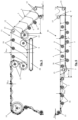
- FIG. 2 shows the ring elevator of FIG. 1 illustrated in back view
- FIG. 3 shows parts of a root crop harvester, comprising a ring elevator according to some embodiments of the invention and are schematically illustrated in perspective;
- FIG. 4 shows the ring elevator of the root crop harvester of FIG. 3 illustrated separately in back view
- FIG. 5 shows the top part of the ring elevator of FIG. 4 illustrated in more detail
- FIG. 6 shows the bottom part of the ring elevator of FIG. 4 illustrated in more detail
- FIG. 7 shows the descending part of the ring elevator of FIG. 2 illustrated in more detail
- FIG. 8 shows the descending part of the ring elevator of FIG. 4 illustrated in more detail
- FIG. 9 shows the total volume and the useful volume for a basket of a ring elevator according to the prior art schematically illustrated
- FIG. 10 shows the total volume and the useful volume for a basket of a ring elevator according to some embodiments of the invention schematically illustrated
- FIG. 11 shows the drop height for a root crop illustrated with both the feeding unit and the loading zone being horizontal
- FIG. 12 shows the drop height for a root crop illustrated when the feeding unit is horizontal, but the loading zone is descending.
- the length of the elevator ( 2 ) is the dimension of the elevator ( 2 ) in the length or travel direction (Y) of the root crop harvester ( 1 ) in which it is installed
- the width of the elevator ( 2 ) is the dimension of this elevator ( 2 ) in a horizontal direction (X) perpendicular to this travel direction (Y) of the root crop harvester ( 1 ) in which it is installed
- the height of the elevator ( 2 ) is the dimension of this elevator ( 2 ) in a vertical direction (Z) of the root crop harvester ( 1 ) in which it is installed.
- FIG. 3 illustrates a possible position of a ring elevator ( 2 ) in a root crop harvester ( 1 ).
- a root crop harvester ( 1 ) comprises a crop-digger section with e.g. one or more harvesting shares, which are not illustrated.
- a sieving unit ( 27 ) comprises sieving conveyors ( 37 ), a feeding conveyor ( 31 ), a pintle belt ( 35 ) and axial rollers ( 36 ).
- This sieving unit ( 27 ) is positioned downstream of the harvesting shares for transporting root crops ( 8 ) towards the ring elevator ( 2 ) and in the meantime, to sieve dirt from the harvested root crops ( 8 ).
- the elevator ( 2 ) With the elevator ( 2 ), the root crops ( 8 ) are then lifted towards a discharge conveyor ( 28 ) onto a transfer elevator ( 29 ).
- the feeding conveyor ( 31 ) preferably does not have a sieve function when passing through the ring elevator ( 2 ).
- the root crop harvester ( 1 ) is provided with a bunker instead of a transfer elevator ( 29 ) and/or without axial rollers ( 36 ), and/or without pintle belt ( 35 ) and/or with the ring elevator ( 2 ) being positioned fully at the back of the root crop harvester ( 1 ), and/or with additional or less conveyors ( 28 , 29 , 31 , 34 , 37 ) and/or other transfer means etc.
- the parts of the harvester machine ( 1 ) besides the ring elevator ( 2 ) can be of any known design.
- FIGS. 1 - 2 , 7 and 9 a ring elevator ( 2 ) of the prior art is illustrated.
- FIGS. 3 - 6 , 8 and 10 Both this ring elevator ( 2 ) of the prior art and the illustrated embodiment of a ring elevator ( 2 ) according to the invention ( FIGS. 3 - 6 , 8 and 10 ) comprise:
- the closed paths are defined by driving rollers ( 14 ), deflection rollers ( 15 ) and carrying rollers ( 16 ) onto which the strips ( 3 , 4 ) are arranged and pass while being driven.
- the transverse elements ( 5 , 6 ) may include bars and/or slats and/or profiles and/or tubes and can be made of metal or plastic. If necessary, they can be provided with a cover. In addition, they can also be provided with one or more indentations.
- transverse bars ( 5 , 6 ) that are riveted to the strips ( 3 , 4 ), belts, chains or the like, as this provides a strong connection.
- Flexible support elements ( 7 ) are each attached to a first transverse element ( 5 ) and to a second transverse element ( 6 ).
- These flexible support elements ( 7 ) may e.g. be made of plastic. These may be attached to the transverse elements ( 5 , 6 ) as in the prior art, or as described in BE 2019 / 5181 .
- an elevator ( 2 ) to which at least one embodiment of the invention relates does not have a sieving function, it is possible to provide such flexible support elements ( 7 ) with perforations, this primarily in order to reduce weight of the ring elevator ( 2 ).
- the first strips ( 3 ), belts, chains or the like are arranged around the second strips ( 4 ), belts, chains or the like in such a way that the flexible support elements ( 7 ) form baskets for the transport of the root crops ( 8 ) in an ascending part ( 32 ) of their path and are stretched out to save space in a descending part ( 33 ) of their path, where the root crops ( 8 ) do not have to be transported.
- the strips ( 3 , 4 ) are therefore positioned at a distance, which, when in use, varies along the paths between a minimum distance (d min ) and a maximum distance (d max ).
- the distance between the strips ( 3 , 4 ), belts, chains or the like equals a carrier distance (c), for forming the baskets ( 7 ) for receiving the root crops ( 8 ).
- the second strips ( 4 ), belts, chains or the like begin to rise towards the ascending part ( 32 ) in an ascending point ( 9 ) of the second path.
- the distance In a descending part ( 33 ) of the paths, the distance equals said minimum distance (d min ).
- the ring elevator ( 2 ) comprises a loading zone ( 10 ), situated before the ascending point ( 9 ), for loading root crops ( 8 ) on the flexible support elements ( 7 ) and an unloading zone ( 11 ), situated after the ascending part ( 32 ), for unloading root crops ( 8 ) from the flexible support elements ( 7 ).
- the distance between the first strips ( 3 ), belts, chains or the like is larger than the distance between the second strips ( 4 ), belts, chains or the like.
- the first strips ( 3 ), belts, chains or the like are thus placed on both sides of the second strips ( 4 ), belts, chains or the like. It is however also possible to position the first strips ( 3 ), belts, chains or the like at a smaller distance than the second strips ( 4 ), belts, chains or the like, such that the second strips ( 4 ), belts, chains or the like are placed on both sides of the first strips ( 3 ), belts, chains or the like.
- FIGS. 9 and 10 two baskets ( 7 ) are illustrated arranged above each other, with the transverse elements ( 5 , 6 ) to which they are attached placed at said carrier distance (c) from each other and freely hanging down.
- Points B and D represent the places where first transverse elements ( 5 ) are situated and points A and C represent the places where second transverse elements ( 6 ) are situated. Seen in cross-section, these baskets ( 7 ) then theoretically take up a chainline.
- V t The total volume (V t ) of these baskets ( 7 ) then equals the volume between the parallel transverse elements ( 5 , 6 ), to which these baskets ( 7 ) are hung and is illustrated as the area (ABCD) in FIGS. 9 and 10 . This is the fully shaded zone in these figures.
- This total volume is per basket ( 7 ) delimited by a plane through the transverse elements ( 5 , 6 ) to which said basket ( 7 ) is attached, a plane through the transverse elements ( 5 , 6 ) to which the basket ( 7 ) hanging just below it is attached, a plane through the first transverse elements ( 5 ) to which both said baskets ( 7 ) are attached and a plane through the second transverse elements ( 6 ) to which both said baskets ( 7 ) are attached.
- the surface area of area (ABCD) is to be multiplied by the length of the transverse elements ( 5 , 6 ).
- this zone also equals the volume delimited between a basket ( 7 ), freely hanging downwards, the basket ( 7 ) hanging just below it, the plane through the first transvers elements ( 5 ) to which these baskets ( 7 ) are attached and the plane through the second transverse elements ( 6 ) to which these baskets ( 7 ) are attached (again the corresponding surface area as illustrated in FIG. 9 multiplied by the length of the transverse elements).
- the sum of these theoretical total volumes of all the (parts of) baskets ( 7 ) extending in said ascending part ( 32 ) together form the total volume (V t ) in this ascending part ( 32 ).
- the useful volume (V u ) of a basket ( 7 ) can be defined as the volume, delimited by said basket ( 7 ), freely hanging downwards, a plane through the transverse elements ( 5 , 6 ) to which this basket ( 7 ) is attached and, in case the basket just below it extends up to above the lowest point of this basket hanging down, a plane through the transverse elements ( 5 , 6 ) to which the basket ( 7 ) just below it is attached.
- this is illustrated as the area (ABE).
- FIG. 10 this is illustrated as the area (AFGB).
- this theoretical useful volume equals the volume delimited by said basket ( 7 ) and a plane through the transverse elements ( 5 , 6 ) to which this basket ( 7 ) is attached, minus the volume which the basket placed just above it and also freely hanging downwards, will occupy therein.
- the sum of these theoretical useful volumes of all the (parts of) baskets ( 7 ) extending within the total volume (V t ) together form the useful volume (V u ) in this ascending part ( 32 ).
- V u there is a volume (illustrated with the diagonally shaded zones in these figures) which is theoretically not finable with root crops ( 8 ).
- the useful volume (V u ) takes up far less than 50% of the total volume (V t ). In the illustrated embodiment according to the invention, this useful volume (V u ) takes up about 76% of the total volume (V t ).
- the mentioned volumes (V t , V u ) are theoretically defined. For both the total volume (V t ) as the useful volume (V u ) the illustrated surface areas could alternatively be multiplied by e.g. the length the baskets ( 7 ) are taking up in the elevator ( 2 ), or e.g. the width over which crops will extend. For the percentages mentioned, it is irrelevant whether in practice the baskets ( 7 ) have the same length as the transverse elements ( 5 , 6 ) or whether the crops occupy this full length. The proportions of the volumes (V t , V u ) will remain the same, irrespective of which length is taken for calculating the volumes (V t , V u ).
- FIGS. 11 and 12 the effect of first strips ( 3 ), belts, chains or the like descending in the loading zone ( 10 ) is illustrated.
- the first strips ( 3 ), belts, chains or the like run along to the indicated travel direction (T).
- the drop height (D h,1 , D h,2 ) is the height of which a root crop ( 8 ) is falling in the air.
- the filling height (D f,1 , D f,2 ) is the height between the feeding unit ( 36 ) and the underlying part which is not a root crop ( 8 ).
- a similar effect, limiting the drop height can be obtained by setting up the discharge conveyor ( 28 ) not parallel to the second strips ( 4 ), belts, chains or the like.
Landscapes
- Life Sciences & Earth Sciences (AREA)
- Environmental Sciences (AREA)
- Engineering & Computer Science (AREA)
- Mechanical Engineering (AREA)
- Harvesting Machines For Root Crops (AREA)
Applications Claiming Priority (3)
| Application Number | Priority Date | Filing Date | Title |
|---|---|---|---|
| EP19200191.5A EP3797571B1 (fr) | 2019-09-27 | 2019-09-27 | Élévateur en anneau pour le levage de plantes racines dans une moissonneuse de plantes racines et moissonneuse de plantes racines comprenant un tel élévateur en anneau |
| EPEP19200191.5 | 2019-09-27 | ||
| EP19200191 | 2019-09-27 |
Publications (2)
| Publication Number | Publication Date |
|---|---|
| US20210092897A1 US20210092897A1 (en) | 2021-04-01 |
| US11903336B2 true US11903336B2 (en) | 2024-02-20 |
Family
ID=68084657
Family Applications (1)
| Application Number | Title | Priority Date | Filing Date |
|---|---|---|---|
| US17/015,113 Active 2042-12-04 US11903336B2 (en) | 2019-09-27 | 2020-09-09 | Ring elevator for lifting root crops in a root crop harvester and root crop harvester comprising such a ring elevator |
Country Status (3)
| Country | Link |
|---|---|
| US (1) | US11903336B2 (fr) |
| EP (1) | EP3797571B1 (fr) |
| CA (1) | CA3092031C (fr) |
Families Citing this family (1)
| Publication number | Priority date | Publication date | Assignee | Title |
|---|---|---|---|---|
| WO2023233298A1 (fr) * | 2022-05-30 | 2023-12-07 | Turnerland Manufacturing (Pty) Ltd | Récolteuse de cultures de legumes racines |
Citations (12)
| Publication number | Priority date | Publication date | Assignee | Title |
|---|---|---|---|---|
| US867495A (en) * | 1905-02-13 | 1907-10-01 | Allis Chalmers | Feed means for traction-elevators. |
| US2751062A (en) * | 1953-08-25 | 1956-06-19 | Vernal B Forbes | Dump elevator |
| US2753979A (en) * | 1951-07-11 | 1956-07-10 | Kalb Agricultural Ass Inc De | Elevating conveyor |
| US2828002A (en) | 1955-11-09 | 1958-03-25 | Hewlett M Sawrie | Sling conveyor |
| US2956668A (en) * | 1957-07-06 | 1960-10-18 | Fioravanti Jean | Conveyor system |
| GB1038831A (en) | 1963-01-29 | 1966-08-10 | Elliott Brothers London Ltd | Improvements in or relating to endless conveyors |
| DE1228190B (de) | 1965-02-15 | 1966-11-03 | Herbert Knobbe | Becherfoerderer |
| US3741372A (en) * | 1971-06-28 | 1973-06-26 | Xerox Corp | Conveyor for developer apparatus |
| US4333561A (en) | 1978-07-10 | 1982-06-08 | Schlegel Hans J | Elevator head material guide means |
| US4842076A (en) * | 1985-08-16 | 1989-06-27 | Franz Grumme Landmaschinenfabrik GmbH & Co. KG | Potato harvester |
| US5660266A (en) * | 1992-07-17 | 1997-08-26 | Conrad Scholtz Gmbh | Pocket belt conveyor |
| US6267226B1 (en) | 1996-10-04 | 2001-07-31 | Paul Laurence Jarmain | Bucket elevator improvements |
-
2019
- 2019-09-27 EP EP19200191.5A patent/EP3797571B1/fr active Active
-
2020
- 2020-09-03 CA CA3092031A patent/CA3092031C/fr active Active
- 2020-09-09 US US17/015,113 patent/US11903336B2/en active Active
Patent Citations (12)
| Publication number | Priority date | Publication date | Assignee | Title |
|---|---|---|---|---|
| US867495A (en) * | 1905-02-13 | 1907-10-01 | Allis Chalmers | Feed means for traction-elevators. |
| US2753979A (en) * | 1951-07-11 | 1956-07-10 | Kalb Agricultural Ass Inc De | Elevating conveyor |
| US2751062A (en) * | 1953-08-25 | 1956-06-19 | Vernal B Forbes | Dump elevator |
| US2828002A (en) | 1955-11-09 | 1958-03-25 | Hewlett M Sawrie | Sling conveyor |
| US2956668A (en) * | 1957-07-06 | 1960-10-18 | Fioravanti Jean | Conveyor system |
| GB1038831A (en) | 1963-01-29 | 1966-08-10 | Elliott Brothers London Ltd | Improvements in or relating to endless conveyors |
| DE1228190B (de) | 1965-02-15 | 1966-11-03 | Herbert Knobbe | Becherfoerderer |
| US3741372A (en) * | 1971-06-28 | 1973-06-26 | Xerox Corp | Conveyor for developer apparatus |
| US4333561A (en) | 1978-07-10 | 1982-06-08 | Schlegel Hans J | Elevator head material guide means |
| US4842076A (en) * | 1985-08-16 | 1989-06-27 | Franz Grumme Landmaschinenfabrik GmbH & Co. KG | Potato harvester |
| US5660266A (en) * | 1992-07-17 | 1997-08-26 | Conrad Scholtz Gmbh | Pocket belt conveyor |
| US6267226B1 (en) | 1996-10-04 | 2001-07-31 | Paul Laurence Jarmain | Bucket elevator improvements |
Non-Patent Citations (1)
| Title |
|---|
| Search Report European Patent Application EP19200191, dated Apr. 14, 2020. |
Also Published As
| Publication number | Publication date |
|---|---|
| EP3797571A1 (fr) | 2021-03-31 |
| EP3797571C0 (fr) | 2023-09-27 |
| US20210092897A1 (en) | 2021-04-01 |
| EP3797571B1 (fr) | 2023-09-27 |
| CA3092031A1 (fr) | 2021-03-27 |
| CA3092031C (fr) | 2023-05-23 |
Similar Documents
| Publication | Publication Date | Title |
|---|---|---|
| US11903336B2 (en) | Ring elevator for lifting root crops in a root crop harvester and root crop harvester comprising such a ring elevator | |
| CA2684830A1 (fr) | Systeme de dechargement de matiere agricole | |
| NO162441B (no) | Potetopptager. | |
| US20110094201A1 (en) | Center Draper Belt With Crop Conveying Features | |
| US10925215B2 (en) | Slat-bar cross-members in a feederhouse crop-conveying system | |
| US11634283B2 (en) | Paddle conveyor system | |
| EP3797572B1 (fr) | Moissonneuse de plantes racines comprenant un ascenseur de levage de plantes racines | |
| CN108142089A (zh) | 一种高效智能收割机 | |
| EP0915037B1 (fr) | Machine agricole avec système élévateur | |
| US9789798B2 (en) | Stick removal mechanism for nut harvesting | |
| CN108496516A (zh) | 前置双垄甘薯起收机 | |
| CN210746063U (zh) | 一种马铃薯收获机 | |
| JP2023021584A (ja) | 自動じゃが芋収穫機 | |
| US1935908A (en) | Harvester | |
| US2093920A (en) | Potato harvester | |
| UA74632C2 (en) | Self-propelled beet harvester | |
| KR20160046971A (ko) | 콤바인용 곡물저장탱크 승강장치 | |
| US20240101365A1 (en) | Cleanup Conveyor System | |
| CN116897675A (zh) | 一种联合智能收获机 | |
| JP3499760B2 (ja) | 農産物収穫機 | |
| CN110199657B (zh) | 一种马铃薯收获机用全自动卸料箱 | |
| CN215823569U (zh) | 一种马铃薯洋葱收获机回转提升筛分装置 | |
| KR101450639B1 (ko) | 적재장치 | |
| JPH0135646Y2 (fr) | ||
| RU2164736C1 (ru) | Полотно пруткового элеватора |
Legal Events
| Date | Code | Title | Description |
|---|---|---|---|
| FEPP | Fee payment procedure |
Free format text: ENTITY STATUS SET TO UNDISCOUNTED (ORIGINAL EVENT CODE: BIG.); ENTITY STATUS OF PATENT OWNER: SMALL ENTITY |
|
| FEPP | Fee payment procedure |
Free format text: ENTITY STATUS SET TO SMALL (ORIGINAL EVENT CODE: SMAL); ENTITY STATUS OF PATENT OWNER: SMALL ENTITY |
|
| STPP | Information on status: patent application and granting procedure in general |
Free format text: APPLICATION DISPATCHED FROM PREEXAM, NOT YET DOCKETED |
|
| STPP | Information on status: patent application and granting procedure in general |
Free format text: DOCKETED NEW CASE - READY FOR EXAMINATION |
|
| STPP | Information on status: patent application and granting procedure in general |
Free format text: NON FINAL ACTION MAILED |
|
| STPP | Information on status: patent application and granting procedure in general |
Free format text: RESPONSE TO NON-FINAL OFFICE ACTION ENTERED AND FORWARDED TO EXAMINER |
|
| STPP | Information on status: patent application and granting procedure in general |
Free format text: NOTICE OF ALLOWANCE MAILED -- APPLICATION RECEIVED IN OFFICE OF PUBLICATIONS |
|
| AS | Assignment |
Owner name: DEWULF NV, BELGIUM Free format text: ASSIGNMENT OF ASSIGNORS INTEREST;ASSIGNORS:VAN ISEGHEM, JOERI;DE BOE, GERT;REEL/FRAME:066117/0031 Effective date: 20200904 |
|
| STPP | Information on status: patent application and granting procedure in general |
Free format text: PUBLICATIONS -- ISSUE FEE PAYMENT VERIFIED |
|
| STCF | Information on status: patent grant |
Free format text: PATENTED CASE |